Embed Size (px)
Citation preview
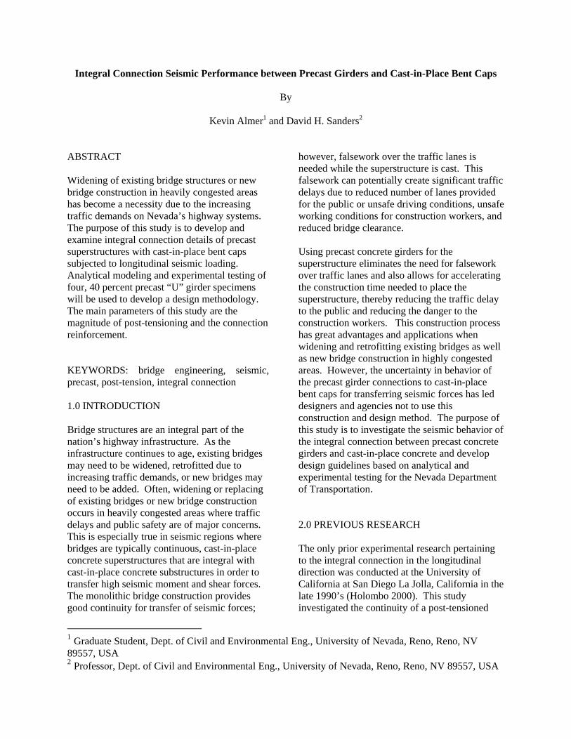
Integral Connection Seismic Performance between Precast Girders and Cast-in-Place Bent Caps By Kevin Almer1 and David H. Sanders2
1 Graduate Student, Dept. of Civil and Environmental Eng., University of Nevada, Reno, Reno, NV 89557, USA 2 Professor, Dept. of Civil and Environmental Eng., University of Nevada, Reno, Reno, NV 89557, USA
ABSTRACT Widening of existing bridge structures or new bridge construction in heavily congested areas has become a necessity due to the increasing traffic demands on Nevada’s highway systems. The purpose of this study is to develop and examine integral connection details of precast superstructures with cast-in-place bent caps subjected to longitudinal seismic loading. Analytical modeling and experimental testing of four, 40 percent precast “U” girder specimens will be used to develop a design methodology. The main parameters of this study are the magnitude of post-tensioning and the connection reinforcement. KEYWORDS: bridge engineering, seismic, precast, post-tension, integral connection 1.0 INTRODUCTION
Bridge structures are an integral part of the nation’s highway infrastructure. As the infrastructure continues to age, existing bridges may need to be widened, retrofitted due to increasing traffic demands, or new bridges may need to be added. Often, widening or replacing of existing bridges or new bridge construction occurs in heavily congested areas where traffic delays and public safety are of major concerns. This is especially true in seismic regions where bridges are typically continuous, cast-in-place concrete superstructures that are integral with cast-in-place concrete substructures in order to transfer high seismic moment and shear forces. The monolithic bridge construction provides good continuity for transfer of seismic forces;
however, falsework over the traffic lanes is needed while the superstructure is cast. This falsework can potentially create significant traffic delays due to reduced number of lanes provided for the public or unsafe driving conditions, unsafe working conditions for construction workers, and reduced bridge clearance. Using precast concrete girders for the superstructure eliminates the need for falsework over traffic lanes and also allows for accelerating the construction time needed to place the superstructure, thereby reducing the traffic delay to the public and reducing the danger to the construction workers. This construction process has great advantages and applications when widening and retrofitting existing bridges as well as new bridge construction in highly congested areas. However, the uncertainty in behavior of the precast girder connections to cast-in-place bent caps for transferring seismic forces has led designers and agencies not to use this construction and design method. The purpose of this study is to investigate the seismic behavior of the integral connection between precast concrete girders and cast-in-place concrete and develop design guidelines based on analytical and experimental testing for the Nevada Department of Transportation. 2.0 PREVIOUS RESEARCH The only prior experimental research pertaining to the integral connection in the longitudinal direction was conducted at the University of California at San Diego La Jolla, California in the late 1990’s (Holombo 2000). This study investigated the continuity of a post-tensioned
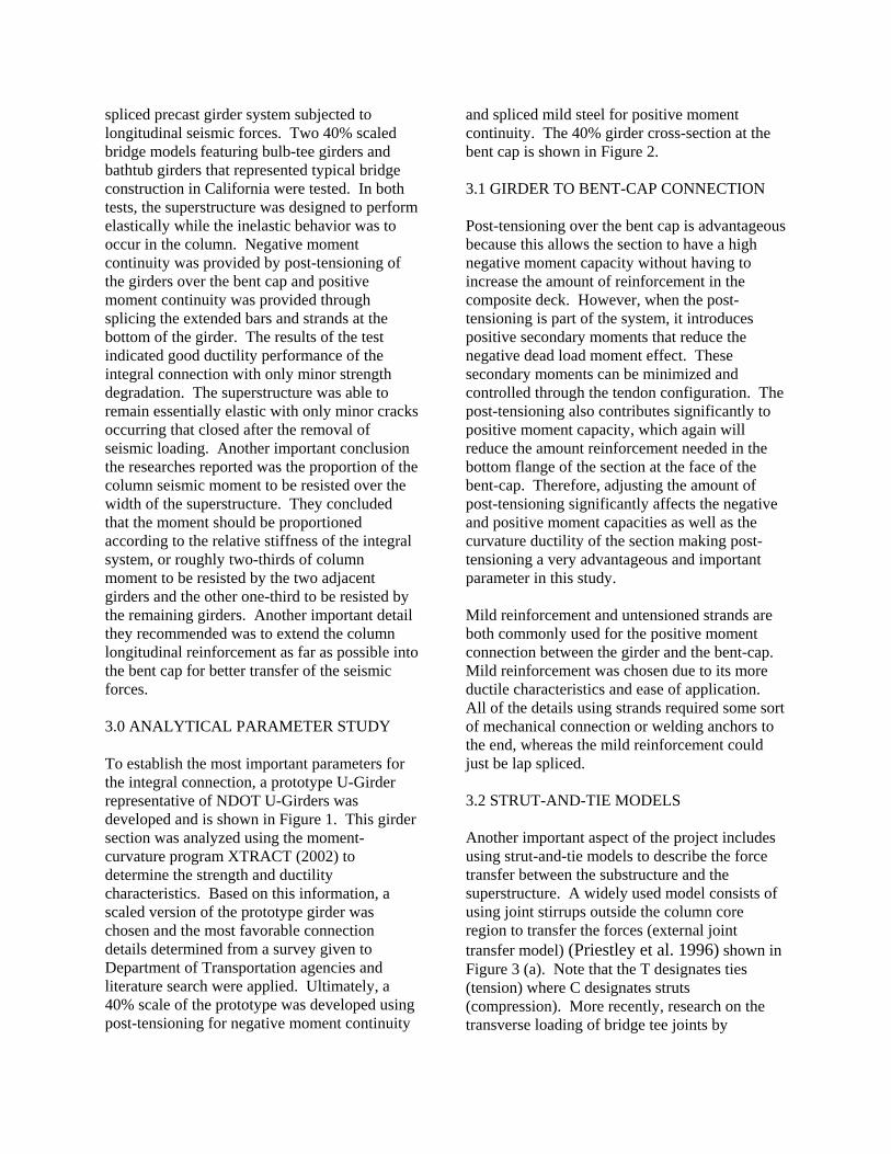
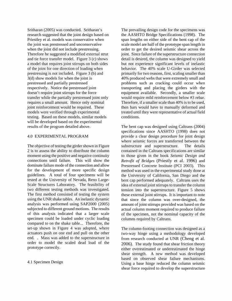
spliced precast girder system subjected to longitudinal seismic forces. Two 40% scaled bridge models featuring bulb-tee girders and bathtub girders that represented typical bridge construction in California were tested. In both tests, the superstructure was designed to perform elastically while the inelastic behavior was to occur in the column. Negative moment continuity was provided by post-tensioning of the girders over the bent cap and positive moment continuity was provided through splicing the extended bars and strands at the bottom of the girder. The results of the test indicated good ductility performance of the integral connection with only minor strength degradation. The superstructure was able to remain essentially elastic with only minor cracks occurring that closed after the removal of seismic loading. Another important conclusion the researches reported was the proportion of the column seismic moment to be resisted over the width of the superstructure. They concluded that the moment should be proportioned according to the relative stiffness of the integral system, or roughly two-thirds of column moment to be resisted by the two adjacent girders and the other one-third to be resisted by the remaining girders. Another important detail they recommended was to extend the column longitudinal reinforcement as far as possible into the bent cap for better transfer of the seismic forces. 3.0 ANALYTICAL PARAMETER STUDY To establish the most important parameters for the integral connection, a prototype U-Girder representative of NDOT U-Girders was developed and is shown in Figure 1. This girder section was analyzed using the moment-curvature program XTRACT (2002) to determine the strength and ductility characteristics. Based on this information, a scaled version of the prototype girder was chosen and the most favorable connection details determined from a survey given to Department of Transportation agencies and literature search were applied. Ultimately, a 40% scale of the prototype was developed using post-tensioning for negative moment continuity
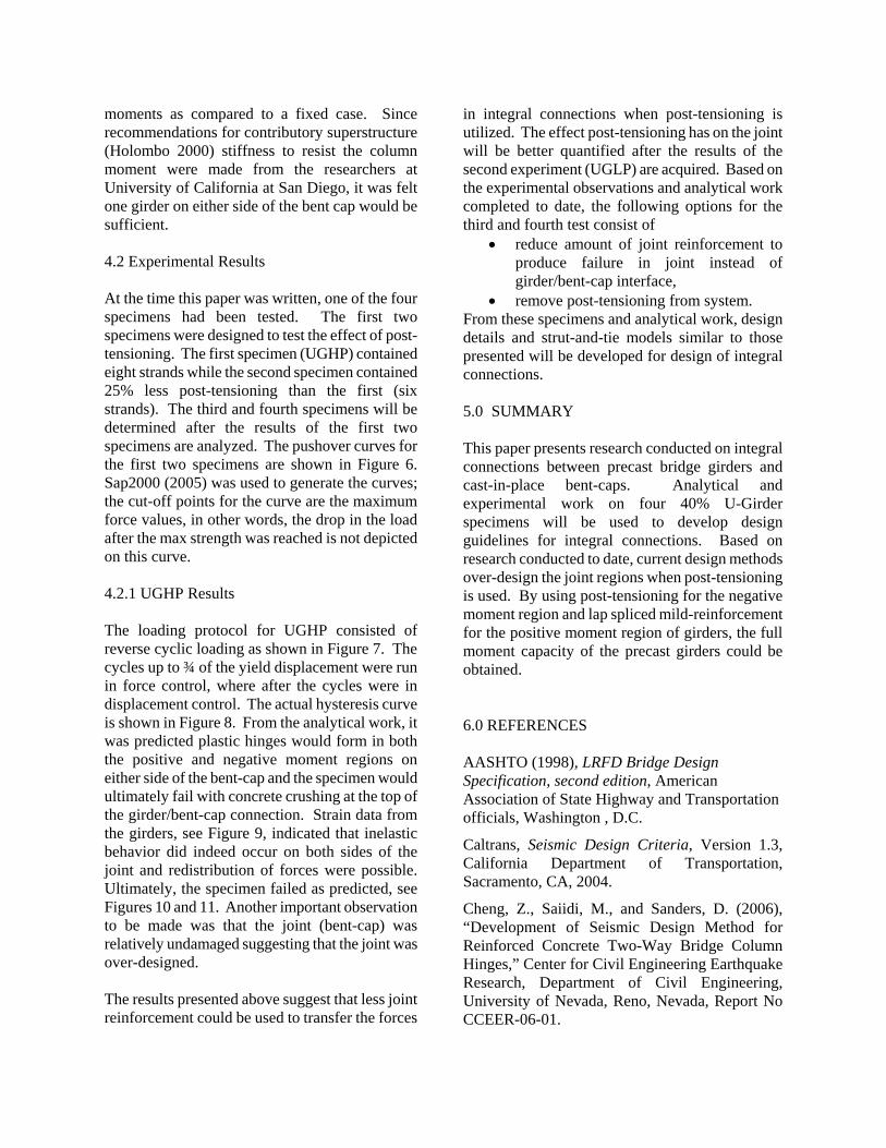
and spliced mild steel for positive moment continuity. The 40% girder cross-section at the bent cap is shown in Figure 2.
3.1 GIRDER TO BENT-CAP CONNECTION Post-tensioning over the bent cap is advantageous because this allows the section to have a high negative moment capacity without having to increase the amount of reinforcement in the composite deck. However, when the post-tensioning is part of the system, it introduces positive secondary moments that reduce the negative dead load moment effect. These secondary moments can be minimized and controlled through the tendon configuration. The post-tensioning also contributes significantly to positive moment capacity, which again will reduce the amount reinforcement needed in the bottom flange of the section at the face of the bent-cap. Therefore, adjusting the amount of post-tensioning significantly affects the negative and positive moment capacities as well as the curvature ductility of the section making post-tensioning a very advantageous and important parameter in this study. Mild reinforcement and untensioned strands are both commonly used for the positive moment connection between the girder and the bent-cap. Mild reinforcement was chosen due to its more ductile characteristics and ease of application. All of the details using strands required some sort of mechanical connection or welding anchors to the end, whereas the mild reinforcement could just be lap spliced. 3.2 STRUT-AND-TIE MODELS Another important aspect of the project includes using strut-and-tie models to describe the force transfer between the substructure and the superstructure. A widely used model consists of using joint stirrups outside the column core region to transfer the forces (external joint transfer model) (Priestley et al. 1996) shown in Figure 3 (a). Note that the T designates ties (tension) where C designates struts (compression). More recently, research on the transverse loading of bridge tee joints by
Sritharan (2005) was conducted. Sritharan’s research suggested that the joint design based on Priestley et al. models was conservative when the joint was prestressed and unconservative when the joint did not include prestressing. Therefore he suggested a modified external strut and tie force transfer model. Figure 3 (c) shows a model that requires joint stirrups on both sides of the joint for one direction of loading when prestressing is not included. Figure 3 (b) and 3(d) show models for when the joint is prestressed and partially prestressed respectively. Notice the prestressed joint doesn’t require joint stirrups for the force transfer while the partially prestressed joint only requires a small amount. Hence only nominal joint reinforcement would be required. These models were verified through experimental testing. Based on these models, similar models will be developed based on the experimental results of the program detailed above. 4.0 EXPERIMENTAL PROGRAM The objective of testing the girder shown in Figure 2 is to assess the ability to distribute the column moment using the positive and negative continuity connections until failure. This will show the dominate failure mode of the connection and allow for the development of more specific design guidelines. A total of four specimens will be tested at the University of Nevada, Reno Large-Scale Structures Laboratory. The feasibility of two different testing methods was investigated. The first method consisted of testing the system using the UNR shake tables. An inelastic dynamic analysis was performed using SAP2000 (2005) subjected to different ground motions. The results of this analysis indicated that a larger scale specimen could be loaded under cyclic loading compared to on the shake table... Therefore, the set-up shown in Figure 4 was adopted, where actuators push on one end and pull on the other end. . Mass was added to the superstructure in order to model the scaled dead load of the prototype correctly. 4.1 Specimen Design
The prevailing design code for the specimens was the AASHTO Bridge Specifications (1998). The span lengths on either side of the bent cap of the scale model are half of the prototype span length in order to get the desired seismic shear across the joint. Since failure of the superstructure connection detail is desired, the column was designed to yield but not experience significant levels of inelastic behavior. The 40% scale U-Girder was selected primarily for two reasons, first, scaling smaller than 40% produced webs that were extremely small and problems such as cracking could occur when transporting and placing the girders with the equipment available. Secondly, a smaller scale would require mild reinforcement below #3 rebar. Therefore, if a smaller scale than 40% is to be used, then bars would have to manually deformed and treated until they were representative of actual field conditions. The bent cap was designed using Caltrans (2004) specifications since AASHTO (1998) does not provide a clear design procedure for joint design where seismic forces are transferred between the substructure and superstructure. The details contained in the Caltrans specifications are similar to those given in the book Seismic Design and Retrofit of Bridges (Priestly et al. 1996) and Prestressed Concrete Institute (PCI 2003). This method was used in the experimental study done at the University of California, San Diego and the bent cap performed adequately. Caltrans uses the idea of external joint stirrups to transfer the column tension into the superstructure. Figure 5 shows these external joint stirrups. It is important to note that since the column was over-designed, the amount of joint stirrups provided was based on the actual column moment required to produce failure of the specimen, not the nominal capacity of the columns required by Caltrans. The column-footing connection was designed as a two-way hinge using a methodology developed from research conducted at UNR (Cheng et al. 2006). The study found that shear friction theory either overestimated or underestimated the hinge shear strength. A new method was developed based on observed shear failure mechanisms. Using a base hinge reduced the column seismic shear force required to develop the superstructure
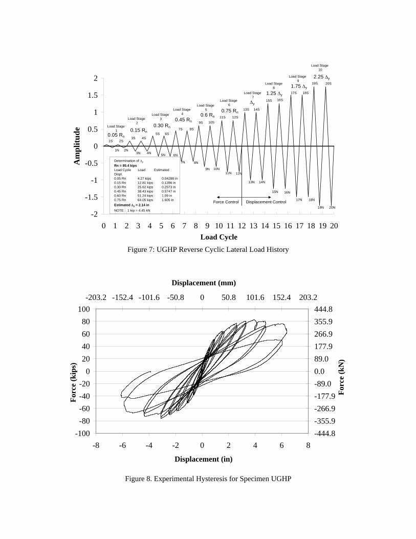
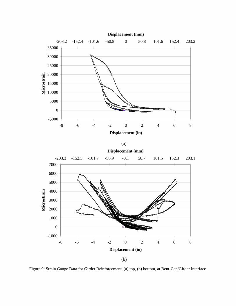
moments as compared to a fixed case. Since recommendations for contributory superstructure (Holombo 2000) stiffness to resist the column moment were made from the researchers at University of California at San Diego, it was felt one girder on either side of the bent cap would be sufficient. 4.2 Experimental Results At the time this paper was written, one of the four specimens had been tested. The first two specimens were designed to test the effect of post-tensioning. The first specimen (UGHP) contained eight strands while the second specimen contained 25% less post-tensioning than the first (six strands). The third and fourth specimens will be determined after the results of the first two specimens are analyzed. The pushover curves for the first two specimens are shown in Figure 6. Sap2000 (2005) was used to generate the curves; the cut-off points for the curve are the maximum force values, in other words, the drop in the load after the max strength was reached is not depicted on this curve. 4.2.1 UGHP Results The loading protocol for UGHP consisted of reverse cyclic loading as shown in Figure 7. The cycles up to ¾ of the yield displacement were run in force control, where after the cycles were in displacement control. The actual hysteresis curve is shown in Figure 8. From the analytical work, it was predicted plastic hinges would form in both the positive and negative moment regions on either side of the bent-cap and the specimen would ultimately fail with concrete crushing at the top of the girder/bent-cap connection. Strain data from the girders, see Figure 9, indicated that inelastic behavior did indeed occur on both sides of the joint and redistribution of forces were possible. Ultimately, the specimen failed as predicted, see Figures 10 and 11. Another important observation to be made was that the joint (bent-cap) was relatively undamaged suggesting that the joint was over-designed. The results presented above suggest that less joint reinforcement could be used to transfer the forces
in integral connections when post-tensioning is utilized. The effect post-tensioning has on the joint will be better quantified after the results of the second experiment (UGLP) are acquired. Based on the experimental observations and analytical work completed to date, the following options for the third and fourth test consist of
• reduce amount of joint reinforcement to produce failure in joint instead of girder/bent-cap interface,
• remove post-tensioning from system. From these specimens and analytical work, design details and strut-and-tie models similar to those presented will be developed for design of integral connections. 5.0 SUMMARY This paper presents research conducted on integral connections between precast bridge girders and cast-in-place bent-caps. Analytical and experimental work on four 40% U-Girder specimens will be used to develop design guidelines for integral connections. Based on research conducted to date, current design methods over-design the joint regions when post-tensioning is used. By using post-tensioning for the negative moment region and lap spliced mild-reinforcement for the positive moment region of girders, the full moment capacity of the precast girders could be obtained. 6.0 REFERENCES AASHTO (1998), LRFD Bridge Design Specification, second edition, American Association of State Highway and Transportation officials, Washington , D.C.
Caltrans, Seismic Design Criteria, Version 1.3, California Department of Transportation, Sacramento, CA, 2004.
Cheng, Z., Saiidi, M., and Sanders, D. (2006), “Development of Seismic Design Method for Reinforced Concrete Two-Way Bridge Column Hinges,” Center for Civil Engineering Earthquake Research, Department of Civil Engineering, University of Nevada, Reno, Nevada, Report No CCEER-06-01.
Holombo, J., Priestley, M.J.N., and Seible, F, “Continuity of Precast Prestressed Spliced-Girder Bridges Under Seismic Loads,” PCI Journal, 45(2), 40–63, March-April, 2000.
PCI, 2003, Precast Prestressed Concrete Bridge Design Manual, second edition, Precast /Prestressed Concrete Institute, Chicago, IL.
Priestley, M.J.N., Seible, F., and Calvi, G.M., Seismic Design and Retrofit of Bridges, John Wiley and Sons, Inc., New York, 1996.
Sap2000, Version Advanced 9.1.1, Computers and Structures, Inc., Berkeley, CA 2005.
Sritharan, Sri, “Strut-and-Tie Analysis of Bridge Tee Joints Subjected to Seismic Actions,” Journal of Structural Engineering, Vol. 131, No.9, September 1, 2005.
XTRACT, Version 2.6.2, Imbsen Software Systems, Sacramento, CA, 2002.
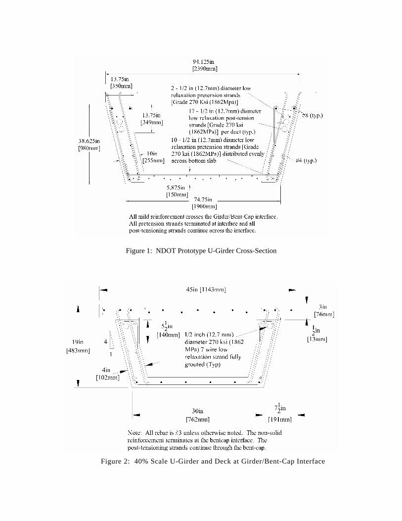
Figure 1: NDOT Prototype U-Girder Cross-Section
Figure 2: 40% Scale U-Girder and Deck at Girder/Bent-Cap Interface
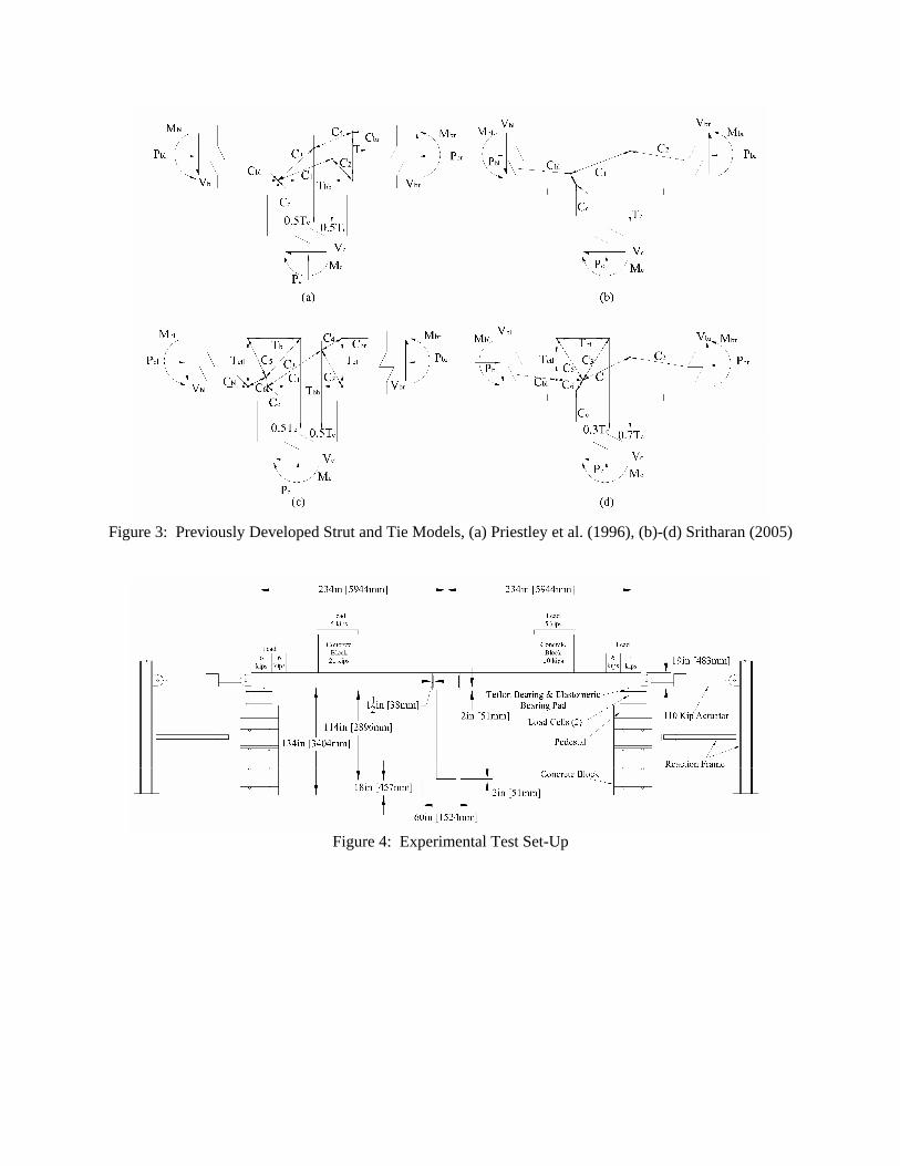
Figure 3: Previously Developed Strut and Tie Models, (a) Priestley et al. (1996), (b)-(d) Sritharan (2005)
Figure 4: Experimental Test Set-Up
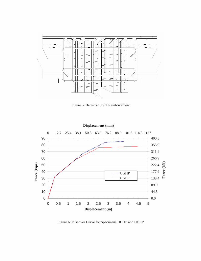
Figure 5: Bent-Cap Joint Reinforcement
0
10
20
30
40
50
60
70
80
90
0 0.5 1 1.5 2 2.5 3 3.5 4 4.5 5Displacement (in)
0.0
44.5
89.0
133.4
177.9
222.4
266.9
311.4
355.9
400.30 12.7 25.4 38.1 50.8 63.5 76.2 88.9 101.6 114.3 127
Displacement (mm)
UGHPUGLPFo
rce
(kip
s)
Forc
e (k
N)
Figure 6: Pushover Curve for Specimens UGHP and UGLP
-2
-1.5
-1
-0.5
0
0.5
1
1.5
2
0 1 2 3 4 5 6 7 8 9 10 11 12 13 14 15 16 17 18 19 20Load Cycle
Am
plitu
de
Force Control Displacement Control
0.05 Rn
0.45 Rn
0.75 Rn
Δy
1.25 Δy
1.75 Δy
Determination of Δy
Rn = 85.4 kips Load Cycle Load Estimated Displ.0.05 Rn 4.27 kips 0.04288 in0.15 Rn 12.81 kips 0.1286 in0.30 Rn 25.62 kips 0.2573 in0.45 Rn 38.43 kips 0.5747 in0.60 Rn 51.24 kips 1.09 in0.75 Rn 64.05 kips 1.605 inEstimated Δy = 2.14 in NOTE : 1 kip = 4.45 kN
0.6 Rn
0.30 Rn0.15 Rn
1S
1N
2S
2N
3S 4S
3N 4N
5S 6S
5N 6N
7S 8S
7N 8N
9S 10S
9N 10N
11S 12S
11N 12N
13S 14S
13N 14N
15S 16S
15N 16N
17S 18S
17N 18N
19S 20S
19N 20N
2.25 Δy
Load Stage 1
Load Stage 2
Load Stage 3
Load Stage 4
Load Stage 5
Load Stage 6
Load Stage 7
Load Stage8
Load Stage 9
Load Stage 10
Figure 7: UGHP Reverse Cyclic Lateral Load History
-100-80-60-40-20
020406080
100
-8 -6 -4 -2 0 2 4 6 8
Displacement (in)
-444.8-355.9-266.9-177.9-89.00.089.0177.9266.9355.9444.8
-203.2 -152.4 -101.6 -50.8 0 50.8 101.6 152.4 203.2
Displacement (mm)
Forc
e (k
ips)
Forc
e (k
N)
Figure 8. Experimental Hysteresis for Specimen UGHP
-5000
0
5000
10000
15000
20000
25000
30000
35000
-8 -6 -4 -2 0 2 4 6 8
Displacement (in)
Mic
rost
rain
-203.2 -152.4 -101.6 -50.8 0 50.8 101.6 152.4 203.2
Displacement (mm)
-1000
0
1000
2000
3000
4000
5000
6000
7000
-8 -6 -4 -2 0 2 4 6 8
Displacement (in)
Mic
rost
rain
-203.3 -152.5 -101.7 -50.9 -0.1 50.7 101.5 152.3 203.1
Displacement (mm)
Figure 9: Strain Gauge Data for Girder Reinforcement, (a) top, (b) bottom, at Bent-Cap/Girder Interface.
(a)
(b)
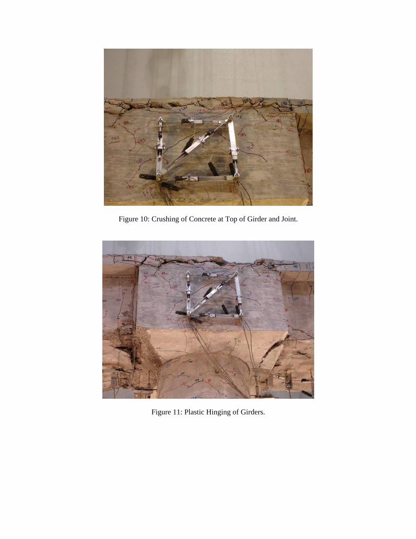
Figure 10: Crushing of Concrete at Top of Girder and Joint.
Figure 11: Plastic Hinging of Girders.