Embed Size (px)
Citation preview
MSS SP-97-2012
Integrally Reinforced Forged
Branch Outlet Fittings – Socket Welding, Threaded,
and Buttwelding Ends
Standard Practice Developed and Approved by the Manufacturers Standardization Society of the Valve and Fittings Industry, Inc. 127 Park Street, NE Vienna, Virginia 22180-4602 Phone: (703) 281-6613 Fax: (703) 281-6671 E-mail: [email protected]
MSS
®
www.mss-hq.org
Copyright MSS Provided by IHS under license with MSS
Not for ResaleNo reproduction or networking permitted without license from IHS
--`,,```,,,,````-`-`,,`,,`,`,,`---
MSS STANDARD PRACTICE SP-97
i
This MSS Standard Practice was developed under the consensus of MSS Technical Committees 105 and the MSS Coordinating Committee. The content of this Standard Practice is the resulting efforts of competent and experienced volunteers to provide an effective, clear, and non-exclusive standard that will benefit the industry as a whole. This MSS Standard Practice describes minimal requirements and is intended as a basis for common practice by the manufacturer, the user, and the general public. The existence of an MSS Standard Practice does not in itself preclude the manufacture, sale, or use of products not conforming to the Standard Practice. Mandatory conformance to this Standard Practice is established only by reference in other documents such as a code, specification, sales contract, or public law, as applicable. MSS has no power, nor does it undertake, to enforce or certify compliance with this document. Any certification or other statement of compliance with the requirements of this Standard Practice shall not be attributable to MSS and is solely the responsibility of the certifier or maker of the statement.
"Unless otherwise specifically noted in this MSS Standard Practice, other standards documents referred to herein are identified by the date of issue that was applicable to this Standard Practice at the date of issue of this Standard Practice (see Annex C). This Standard Practice shall remain silent on the applicability of those other standards of prior or subsequent dates of issue even though applicable provisions may not have changed.”
By publication of this Standard Practice, no position is taken with respect to the validity of any potential claim(s) or of any patent rights in connection therewith. MSS shall not be held responsible for identifying any patent rights. Users are expressly advised that determination of patent rights and the risk of infringement of such rights are entirely their responsibility.
In this Standard Practice, all text, notes, annexes, tables, figures, and references are construed to be essential to the understanding of the message of the standard, and are considered normative unless indicated as “supplemental”. All appendices, if included, that appear in this document are construed as “supplemental”. Note that supplemental information does not include mandatory requirements.
The SI (metric) units and U.S. customary units in this Standard Practice are regarded separately as the standard; each should be used independently of the other. Combining or converting values between the two systems may result in nonconformance with this Standard Practice.
This Standard Practice has been substantially revised from the previous edition. It is suggested that if the user is interested in knowing what changes have been made, that direct page by page comparison should be made of this document.
Non-toleranced dimensions in the Standard Practice are nominal, and, unless otherwise specified, shall be considered "for reference only".
Excerpts of this Standard Practice may be quoted with permission. Credit lines should read ‘Extracted from MSS SP-97-2012 with permission of the publisher, Manufacturers Standardization Society of the Valve and Fittings Industry'. Reproduction and/or electronic transmission or dissemination is prohibited under copyright convention unless written permission is granted by the Manufacturers Standardization Society of the Valve and Fittings Industry Inc. All rights reserved.
Originally Published: June 1987 Current Edition Approved: September 2011 Current Edition Published: May 2012
MSS is a registered trademark of the Manufacturers Standardization Society of the Valve and Fittings Industry, Inc.
Copyright ©, 2012 by Manufacturers Standardization Society
of the Valve and Fittings Industry, Inc.
Printed in U.S.A.
Copyright MSS Provided by IHS under license with MSS
Not for ResaleNo reproduction or networking permitted without license from IHS
--`,,```,,,,````-`-`,,`,,`,`,,`---
MSS STANDARD PRACTICE SP-97
ii
TABLE OF CONTENTS
SECTION PAGE
1 SCOPE ..................................................................................................................................................... 1 2 SERVICE DESIGNATION ..................................................................................................................... 1 3 SIZE ......................................................................................................................................................... 2 4 MARKING .............................................................................................................................................. 2 5 MATERIAL ............................................................................................................................................. 2 6 DESIGN AND DIMENSION .................................................................................................................. 3 7 TESTS ..................................................................................................................................................... 3
TABLE
1 Correlation of Fittings Class with Schedule Number or Wall Designation of Run Pipe for Calculation of Ratings ............................................................................... 1
2 90° Branch Outlets – Buttwelding, U.S. Customary Units ...................................................................... 4 3 90° Branch Outlets – Threaded, U.S. Customary Units .......................................................................... 5 4 90° Branch Outlets – Socket Welding, U.S. Customary Units ................................................................ 6 5 45° Branch Outlets – Buttwelding, U.S. Customary Units ...................................................................... 7 6 45° Branch Outlets – Threaded, U.S. Customary Units .......................................................................... 8 7 45° Branch Outlets – Socket Welding, U.S. Customary Units ................................................................ 9 A2 90° Branch Outlets – Buttwelding, SI (Metric) Units ........................................................................... 10 A3 90° Branch Outlets – Threaded, SI (Metric) Units ................................................................................ 11 A4 90° Branch Outlets – Socket Welding, SI (Metric) Units ...................................................................... 12 A5 45° Branch Outlets – Buttwelding, SI (Metric) Units ........................................................................... 13 A6 45° Branch Outlets – Threaded, SI (Metric) Units ................................................................................ 14 A7 45° Branch Outlets – Socket Welding, SI (Metric) Units ...................................................................... 15 FIGURE
1 Fitting Consolidation Gap Allowance ..................................................................................................... 2 ANNEX
A SI (Metric) Tables A2 through A7 ......................................................................................................... 10 B Design Proof Test .................................................................................................................................. 16 C Referenced Standards and Applicable Dates ......................................................................................... 17
Copyright MSS Provided by IHS under license with MSS
Not for ResaleNo reproduction or networking permitted without license from IHS
--`,,```,,,,````-`-`,,`,,`,`,,`---
MSS STANDARD PRACTICE SP-97
1
1. SCOPE
1.1 This Standard Practice covers essential dimensions, finish, tolerances, testing, marking, material, and minimum strength requirements for 90 and 45 degree integrally reinforced forged branch outlet fittings of buttwelding, socket welding, and threaded types.
1.2 Fittings manufactured to this Standard Practice are designed to make a fully reinforced branch connection in accordance with applicable piping code requirements, when attached, at an opening in a run pipe by means of a full penetration weld.
1.3 Fittings may be made to special dimensions, size, shape, tolerances, or of other wrought material by agreement between the manufacturer and the purchaser.
1.4 Standard Units Tables 2 through 7 show the fitting’s dimensional requirements in customary units or inches (decimal). Tables A2 through A7 show the fitting’s dimensional requirements in SI (metric) units (e.g., millimeters). The values stated in either customary or SI (metric) units are to be regarded separately as the Standard. Within the body text, the SI (metric) units are shown in parenthesis. Combining values from the two systems may result in non-conformance with the Standard Practice. The values stated in each option are not exact equivalents; therefore, each measurement system must be used independently of the other.
2. SERVICE DESIGNATION
2.1 These fittings are designated by their size, type, and class, as shown in Table 1.
2.2 Design temperature and other service conditions shall be limited as provided by the applicable piping code or regulation for the material of construction of the fitting. Within these limits, the maximum allowable pressure of a fitting shall be that computed for straight seamless run pipe of equivalent material (as shown by comparison of composition and mechanical properties in the respective material specifications). The wall thickness used in such computation shall be that tabulated in ASME B36.10M for the size and applicable schedule of pipe reduced by applicable manufacturing tolerances and other allowances (e.g., threaded allowances).
2.3 Any corrosion allowance and any variation in allowable stress due to temperature or other design factors shall be applied to the pipe and fitting alike. The pipe wall thickness corresponding to each Class of fitting, for rating purposes only, is shown in Table 1.
INTEGRALLY REINFORCED FORGED BRANCH OUTLET FITTINGS – SOCKET WELDING, THREADED, AND BUTTWELDING ENDS
TABLE 1 Correlation of Fittings Class with Schedule Number or
Wall Designation of Run Pipe for Calculation of Ratings Class of Fitting Type Branch Size Pipe Wall for Rating Basis (a) Standard Extra Strong Schedule 160 3000 6000
Buttwelding Buttwelding Buttwelding
Threaded & Socket Welding Threaded & Socket Welding
NPS 1/8 – 24 NPS 1/8 – 24 NPS 1/2 – 6 NPS 1/8 – 4 NPS 1/2 – 2
Standard Extra Strong Schedule 160 Extra Strong Schedule 160
Note: (a) The use of run or branch pipe wall thickness either thinner or thicker than shown in Table 1 constitutes a deviation from this Standard Practice and is provided for in Section 1.3.
Copyright MSS Provided by IHS under license with MSS
Not for ResaleNo reproduction or networking permitted without license from IHS
--`,,```,,,,````-`-`,,`,,`,`,,`---
MSS STANDARD PRACTICE SP-97
2
3. SIZE
3.1 The 90 and 45 degree branch outlet sizes considered in this Standard Practice are shown in Table 1. Size on size fittings shall be limited to outlet sizes NPS 1/2 (DN 15) and larger.
3.2 The run (header) pipe size is limited only by the pipe size range listed for each type fitting class.
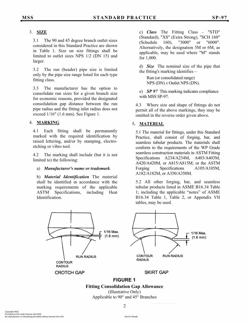
3.3 The manufacturer has the option to consolidate run sizes for a given branch size for economic reasons, provided the designated consolidation gap distance between the run pipe radius and the fitting inlet radius does not exceed 1/16" (1.6 mm). See Figure 1.
4. MARKING
4.1 Each fitting shall be permanently marked with the required identification by raised lettering, and/or by stamping, electro-etching or vibro tool.
4.2 The marking shall include (but it is not limited to) the following:
a) Manufacturer's name or trademark.
b) Material Identification The material shall be identified in accordance with the marking requirements of the applicable ASTM Specifications, including Heat Identification.
c) Class The Fitting Class - "STD" (Standard), "XS" (Extra Strong), "SCH 160" (Schedule 160), "3000" or "6000". Alternatively, the designation 3M or 6M, as applicable, may be used where "M" stands for 1,000.
d) Size The nominal size of the pipe that the fitting's marking identifies –
Run (or consolidated range) NPS (DN) x Outlet NPS (DN).
e) SP 97 This marking indicates compliance with MSS SP-97.
4.3 Where size and shape of fittings do not permit all of the above markings, they may be omitted in the reverse order given above.
5. MATERIAL
5.1 The material for fittings, under this Standard Practice, shall consist of forging, bar, and seamless tubular products. The materials shall conform to the requirements of the WP Grade seamless construction materials in ASTM Fitting Specifications A234/A234M, A403/A403M, A420/A420M, or A815/A815M; or the ASTM Forging Specifications A105/A105M, A182/A182M, or A350/A350M.
5.2 All other forging, bar, and seamless tubular products listed in ASME B16.34 Table 1; including the applicable “notes” of ASME B16.34 Table 1, Table 2, or Appendix VII tables, may be used.
FIGURE 1 Fitting Consolidation Gap Allowance
(Illustrative Only) Applicable to 90° and 45° Branches
Copyright MSS Provided by IHS under license with MSS
Not for ResaleNo reproduction or networking permitted without license from IHS
--`,,```,,,,````-`-`,,`,,`,`,,`---
MSS STANDARD PRACTICE SP-97
3
6. DESIGN AND DIMENSION
6.1 A run pipe having a branch connection is weakened by the opening made in it. The branch connection must reinforce the opening and restore the original strength of the run pipe. It is the intent of this Standard Practice that these integrally reinforced branch outlet fittings and the deposited weld metal used to attach the fittings to run pipes contain all the reinforcement required by the applicable pressure vessel or piping codes without the addition of saddles or pads.
6.1.1 The adequacy of the design of branch connection fittings may be established by mathematical analyses contained in pressure vessel or piping codes, or, at the manufacturer's option, by proof testing in accordance with Section 7 and Annex B. Records of design or proof tests shall be available at the manufacturer's facility for inspection by the purchaser.
6.1.2 The pressure vessel or piping codes referred to in Section 6.1.1 permit a variety of attachment welds for these fittings. Typical branch attachments are shown in ASME B31.1 and B31.3.
6.1.3 Fittings shall be contoured to provide a good fit at the opening in the run pipe. The run attachment weld bevel angle design will vary with the size and type of fitting and with the manufacturer. The size of the run opening is dependent on the manufacturer's specification.
6.2 Buttwelding Buttwelding end finishes shall comply with the standard welding bevel and root face of ASME B16.25.
6.3 Threads Threads in threaded fittings shall comply with ASME B1.20.1 requirements for NPT.
6.3.1 The minimum wall thickness at the root of the thread at the hand tight plane shall be equal to or greater than the nominal wall of the pipe schedule for the appropriate fitting class, as shown in Table 1.
6.4 Socket Weld Socket Weld fittings shall meet the minimum socket depth, minimum socket wall thickness and socket diameter of ASME B16.11 for the appropriate class.
6.5 The contour weld bevel angle on the longitudinal section of the fittings shall be a minimum of 35 degrees. The weld bevel angle on the transverse section of the fitting is based on the manufacturer's specification.
7. TESTS
7.1 Hydrostatic testing of wrought fittings is not required by this Standard Practice. All fittings shall be capable of withstanding, without leakage or impairment of serviceability, a pressure equal to that prescribed in the applicable code or regulation for seamless pipe of equivalent material and schedule listed in Table 1.
7.2 Proof testing is not required, but when performed to meet the requirements of Section 6.1.1, the testing shall be conducted in accordance with Annex B.
Copyright MSS Provided by IHS under license with MSS
Not for ResaleNo reproduction or networking permitted without license from IHS
--`,,```,,,,````-`-`,,`,,`,`,,`---
MSS STANDARD PRACTICE SP-97
4
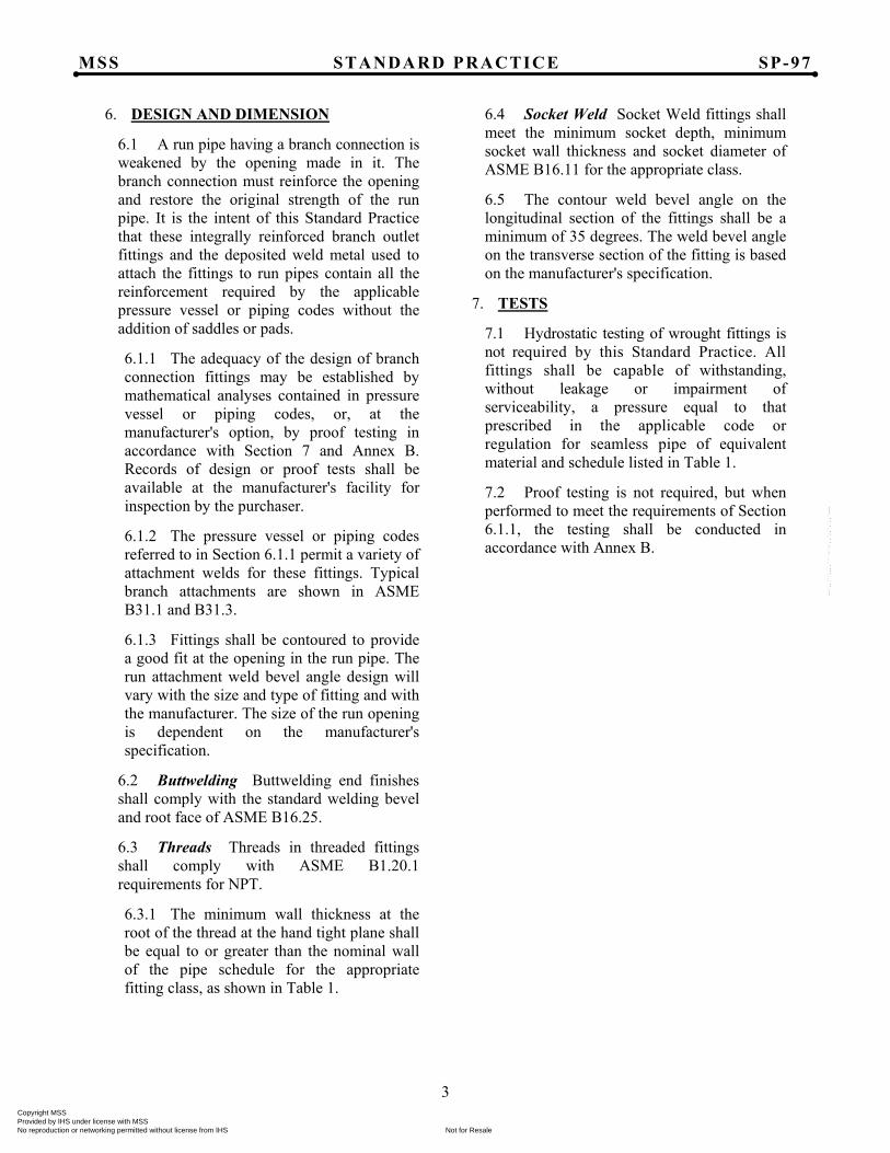
TABLE 2
90° Branch Outlets – Buttwelding, U.S. Customary Units
Dimensions are in inches.
Outlet (NPS)
A (Face of Fitting to Crotch)
Standard Extra Strong Schedule 160 Reducing Full Reducing Full Reducing Full
1/8 0.62 – 0.62 – – – 1/4 0.62 – 0.62 – – – 3/8 0.75 – 0.75 – – – 1/2 0.75 0.75 0.75 0.75 1.12 1.12 3/4 0.88 0.88 0.88 0.88 1.25 1.25 1 1.06 1.06 1.06 1.06 1.50 1.50
11̷4 1.25 1.25 1.25 1.25 1.75 1.75 11̷2 1.31 1.31 1.31 1.31 2.00 2.00 2 1.50 1.50 1.50 1.50 2.18 2.18
21̷2 1.62 1.62 1.62 1.62 2.44 2.44 3 1.75 1.75 1.75 1.75 2.88 2.88
31̷2 1.88 2.00 1.88 2.00 - - 4 2.00 2.00 2.00 2.00 3.31 3.31 5 2.25 2.25 2.25 2.25 3.69 3.69 6 2.38 2.38 3.06 3.06 4.12 4.12 8 2.75 2.75 3.88 3.88 – –
10 3.06 3.06 3.69 3.50 – – 12 3.38 3.38 4.06 3.94 – – 14 3.50 3.50 3.94 4.12 – – 16 3.69 3.69 4.18 4.44 – – 18 3.81 4.06 4.38 4.69 – – 20 4.00 4.62 4.69 5.00 – – 24 4.56 5.38 5.50 5.50 – –
Tolerances: 1⁄8 – 3⁄4 ± .03 in. 1 – 4 ± .06 in. 5 – 12 ± .12 in.
14 – 24 ± .19 in.
Copyright MSS Provided by IHS under license with MSS
Not for ResaleNo reproduction or networking permitted without license from IHS
--`,,```,,,,````-`-`,,`,,`,`,,`---
MSS STANDARD PRACTICE SP-97
5
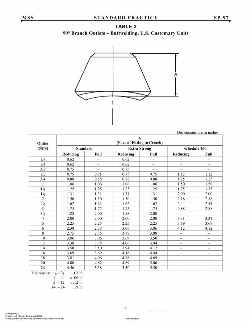
TABLE 3
90° Branch Outlets – Threaded, U.S. Customary Units
Dimensions are in inches.
Outlet (NPS)
A Nom. (Face of Fitting to Crotch)
Threaded Class 3000 Class 6000
1/8 0.75 – 1/4 0.75 – 3/8 0.81 – 1/2 1.00 1.25 3/4 1.06 1.44 1 1.31 1.56
11⁄4 1.31 1.62 11⁄2 1.38 1.69 2 1.50 2.06
21⁄2 1.81 – 3 2.00 – 4 2.25 –
Tolerances: 1⁄8 – 3⁄4 ± .03 in. 1 – 4 ± .06 in.
Copyright MSS Provided by IHS under license with MSS
Not for ResaleNo reproduction or networking permitted without license from IHS
--`,,```,,,,````-`-`,,`,,`,`,,`---
MSS STANDARD PRACTICE SP-97
6
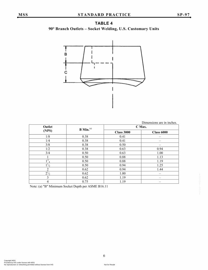
TABLE 4
90° Branch Outlets – Socket Welding, U.S. Customary Units
Dimensions are in inches. Outlet (NPS) B Min.(a)
C Max. Class 3000 Class 6000
1/8 0.38 0.41 – 1/4 0.38 0.41 – 3/8 0.38 0.50 – 1/2 0.38 0.63 0.94 3/4 0.50 0.63 1.00 1 0.50 0.88 1.13
11⁄4 0.50 0.88 1.19 11⁄2 0.50 0.94 1.25 2 0.62 0.94 1.44
21⁄2 0.62 1.00 – 3 0.62 1.19 – 4 0.75 1.19 –
Note: (a) "B" Minimum Socket Depth per ASME B16.11
Copyright MSS Provided by IHS under license with MSS
Not for ResaleNo reproduction or networking permitted without license from IHS
--`,,```,,,,````-`-`,,`,,`,`,,`---
MSS STANDARD PRACTICE SP-97
7
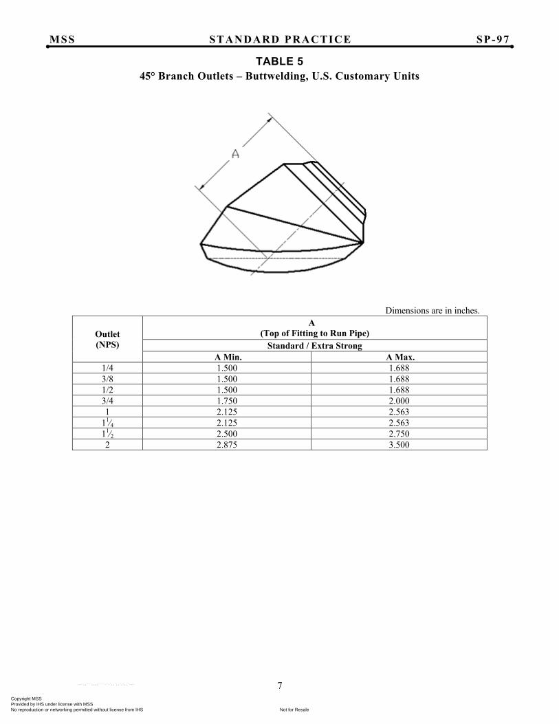
TABLE 5
45° Branch Outlets – Buttwelding, U.S. Customary Units
Dimensions are in inches.
Outlet (NPS)
A (Top of Fitting to Run Pipe)
Standard / Extra Strong A Min. A Max.
1/4 1.500 1.688 3/8 1.500 1.688 1/2 1.500 1.688 3/4 1.750 2.000 1 2.125 2.563
11⁄4 2.125 2.563 11⁄2 2.500 2.750 2 2.875 3.500
Copyright MSS Provided by IHS under license with MSS
Not for ResaleNo reproduction or networking permitted without license from IHS
--`,,```,,,,````-`-`,,`,,`,`,,`---
MSS STANDARD PRACTICE SP-97
8
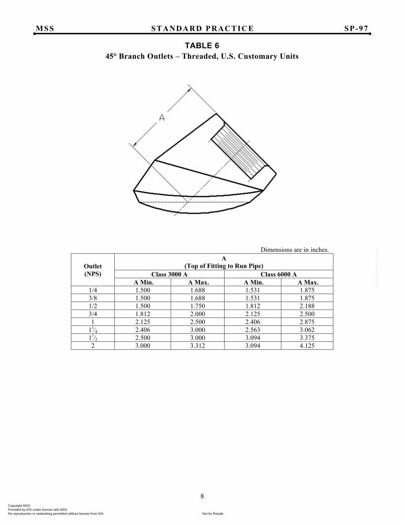
TABLE 6
45° Branch Outlets – Threaded, U.S. Customary Units
Dimensions are in inches.
Outlet (NPS)
A (Top of Fitting to Run Pipe)
Class 3000 A Class 6000 A A Min. A Max. A Min. A Max.
1/4 1.500 1.688 1.531 1.875 3/8 1.500 1.688 1.531 1.875 1/2 1.500 1.750 1.812 2.188 3/4 1.812 2.000 2.125 2.500 1 2.125 2.500 2.406 2.875
11⁄4 2.406 3.000 2.563 3.062 11⁄2 2.500 3.000 3.094 3.375 2 3.000 3.312 3.094 4.125
Copyright MSS Provided by IHS under license with MSS
Not for ResaleNo reproduction or networking permitted without license from IHS
--`,,```,,,,````-`-`,,`,,`,`,,`---
MSS STANDARD PRACTICE SP-97
9
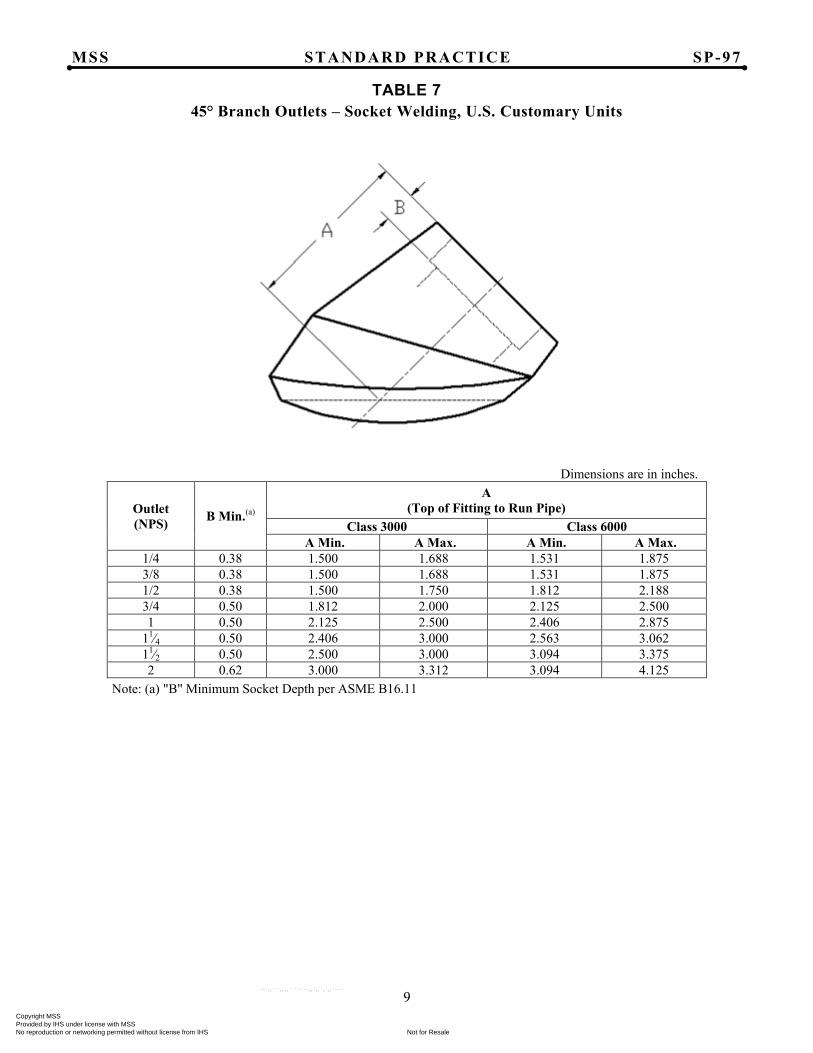
TABLE 7
45° Branch Outlets – Socket Welding, U.S. Customary Units
Dimensions are in inches.
Outlet (NPS) B Min.(a)
A (Top of Fitting to Run Pipe)
Class 3000 Class 6000 A Min. A Max. A Min. A Max.
1/4 0.38 1.500 1.688 1.531 1.875 3/8 0.38 1.500 1.688 1.531 1.875 1/2 0.38 1.500 1.750 1.812 2.188 3/4 0.50 1.812 2.000 2.125 2.500 1 0.50 2.125 2.500 2.406 2.875
11⁄4 0.50 2.406 3.000 2.563 3.062 11⁄2 0.50 2.500 3.000 3.094 3.375 2 0.62 3.000 3.312 3.094 4.125
Note: (a) "B" Minimum Socket Depth per ASME B16.11
Copyright MSS Provided by IHS under license with MSS
Not for ResaleNo reproduction or networking permitted without license from IHS
--`,,```,,,,````-`-`,,`,,`,`,,`---
MSS STANDARD PRACTICE SP-97
10
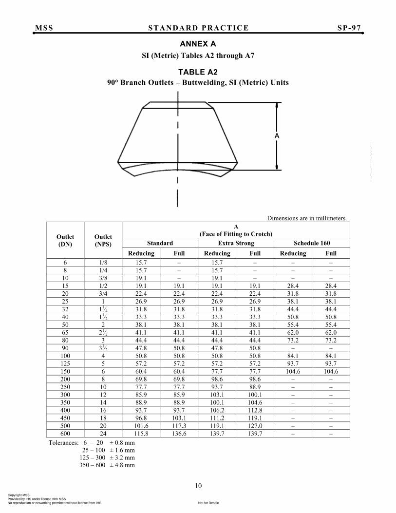
ANNEX A
SI (Metric) Tables A2 through A7
TABLE A2 90° Branch Outlets – Buttwelding, SI (Metric) Units
Dimensions are in millimeters.
Outlet (DN)
Outlet (NPS)
A (Face of Fitting to Crotch)
Standard Extra Strong Schedule 160 Reducing Full Reducing Full Reducing Full
6 1/8 15.7 – 15.7 – – – 8 1/4 15.7 – 15.7 – – –
10 3/8 19.1 – 19.1 – – – 15 1/2 19.1 19.1 19.1 19.1 28.4 28.4 20 3/4 22.4 22.4 22.4 22.4 31.8 31.8 25 1 26.9 26.9 26.9 26.9 38.1 38.1 32 11⁄4 31.8 31.8 31.8 31.8 44.4 44.4 40 11⁄2 33.3 33.3 33.3 33.3 50.8 50.8 50 2 38.1 38.1 38.1 38.1 55.4 55.4 65 21⁄2 41.1 41.1 41.1 41.1 62.0 62.0 80 3 44.4 44.4 44.4 44.4 73.2 73.2 90 31⁄2 47.8 50.8 47.8 50.8 – – 100 4 50.8 50.8 50.8 50.8 84.1 84.1 125 5 57.2 57.2 57.2 57.2 93.7 93.7 150 6 60.4 60.4 77.7 77.7 104.6 104.6 200 8 69.8 69.8 98.6 98.6 – – 250 10 77.7 77.7 93.7 88.9 – – 300 12 85.9 85.9 103.1 100.1 – – 350 14 88.9 88.9 100.1 104.6 – – 400 16 93.7 93.7 106.2 112.8 – – 450 18 96.8 103.1 111.2 119.1 – – 500 20 101.6 117.3 119.1 127.0 – – 600 24 115.8 136.6 139.7 139.7 – –
Tolerances: 6 – 20 ± 0.8 mm 25 – 100 ± 1.6 mm 125 – 300 ± 3.2 mm 350 – 600 ± 4.8 mm
Copyright MSS Provided by IHS under license with MSS
Not for ResaleNo reproduction or networking permitted without license from IHS
--`,,```,,,,````-`-`,,`,,`,`,,`---
MSS STANDARD PRACTICE SP-97
11
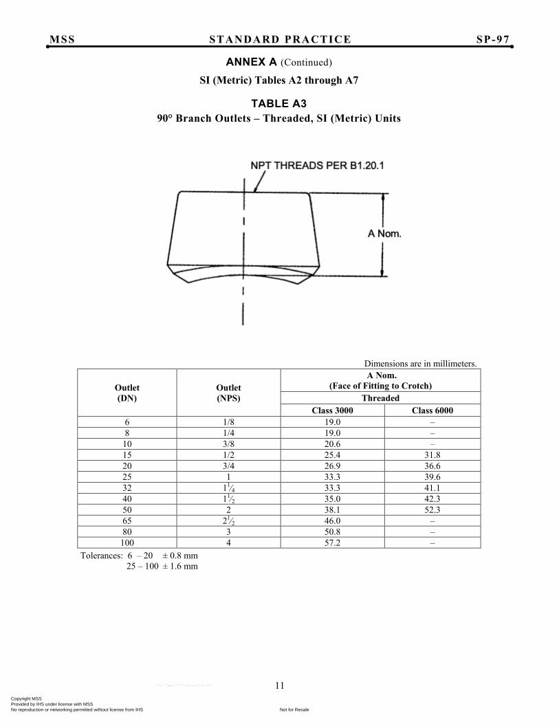
ANNEX A (Continued)
SI (Metric) Tables A2 through A7
TABLE A3 90° Branch Outlets – Threaded, SI (Metric) Units
Dimensions are in millimeters.
Outlet (DN)
Outlet (NPS)
A Nom. (Face of Fitting to Crotch)
Threaded Class 3000 Class 6000
6 1/8 19.0 – 8 1/4 19.0 –
10 3/8 20.6 – 15 1/2 25.4 31.8 20 3/4 26.9 36.6 25 1 33.3 39.6 32 11⁄4 33.3 41.1 40 11⁄2 35.0 42.3 50 2 38.1 52.3 65 21⁄2 46.0 – 80 3 50.8 –
100 4 57.2 – Tolerances: 6 – 20 ± 0.8 mm 25 – 100 ± 1.6 mm
Copyright MSS Provided by IHS under license with MSS
Not for ResaleNo reproduction or networking permitted without license from IHS
--`,,```,,,,````-`-`,,`,,`,`,,`---

MSS STANDARD PRACTICE SP-97
12
ANNEX A (Continued)
SI (Metric) Tables A2 through A7
TABLE A4 90° Branch Outlets – Socket Welding, SI (Metric) Units
Dimensions are in millimeters. Outlet (DN)
Outlet (NPS) B Min.(a)
C Max. Class 3000 Class 6000
6 1/8 9.5 11 – 8 1/4 9.5 11 –
10 3/8 9.5 13 – 15 1/2 9.5 16 24 20 3/4 12.5 16 26 25 1 12.5 23 29 32 11⁄4 12.5 23 31 40 11⁄2 12.5 24 32 50 2 16.0 24 37 65 21⁄2 16.0 26 – 80 3 16.0 31 –
100 4 19.0 31 – Note: (a) "B" Minimum Socket Depths per ASME B16.11
Copyright MSS Provided by IHS under license with MSS
Not for ResaleNo reproduction or networking permitted without license from IHS
--`,,```,,,,````-`-`,,`,,`,`,,`---
MSS STANDARD PRACTICE SP-97
13
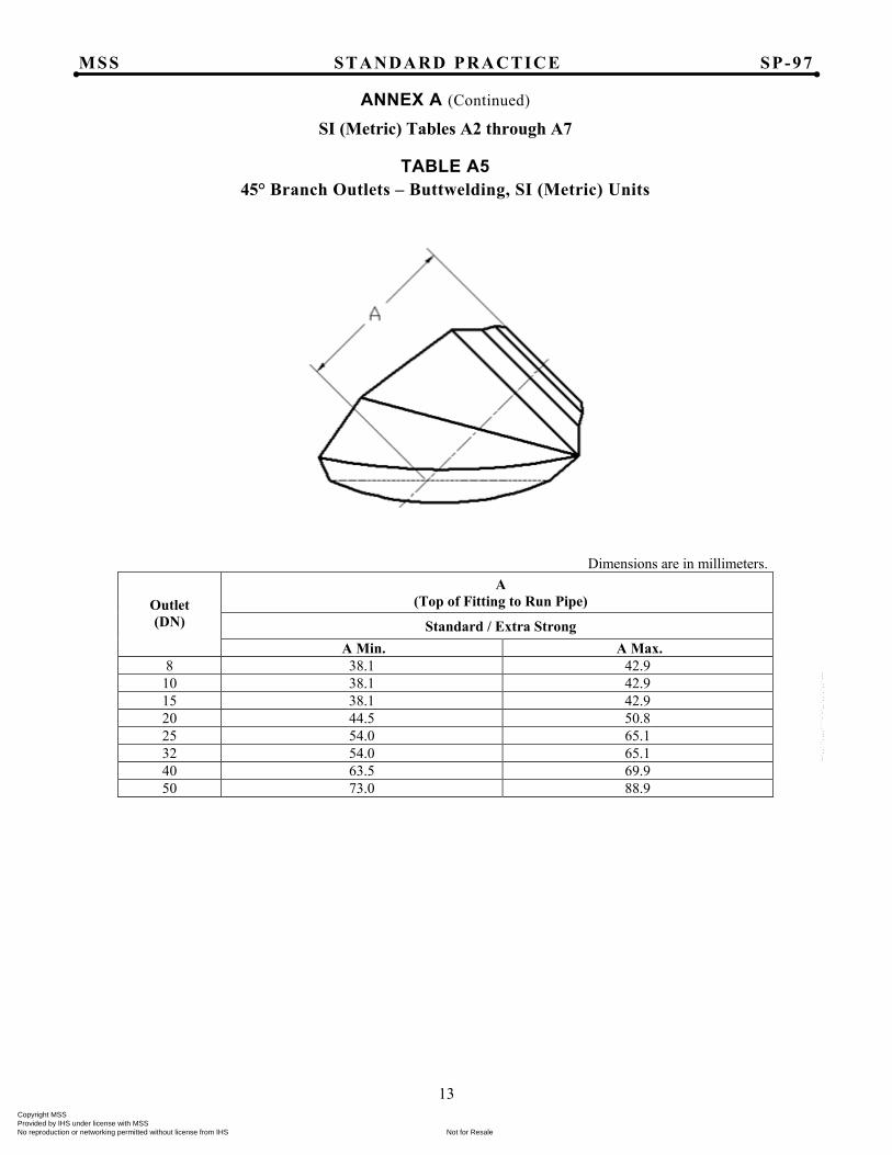
ANNEX A (Continued)
SI (Metric) Tables A2 through A7
TABLE A5 45° Branch Outlets – Buttwelding, SI (Metric) Units
Dimensions are in millimeters.
Outlet (DN)
A (Top of Fitting to Run Pipe)
Standard / Extra Strong A Min. A Max.
8 38.1 42.9 10 38.1 42.9 15 38.1 42.9 20 44.5 50.8 25 54.0 65.1 32 54.0 65.1 40 63.5 69.9 50 73.0 88.9
Copyright MSS Provided by IHS under license with MSS
Not for ResaleNo reproduction or networking permitted without license from IHS
--`,,```,,,,````-`-`,,`,,`,`,,`---

MSS STANDARD PRACTICE SP-97
14
ANNEX A (Continued)
SI (Metric) Tables A2 through A7
TABLE A6 45° Branch Outlets – Threaded, SI (Metric) Units
Dimensions are in millimeters.
Outlet (DN)
A (Top of Fitting to Run Pipe)
Class 3000 Class 6000 A Min. A Max. A Min. A Max.
8 38.1 42.9 38.9 47.6 10 38.1 42.9 38.9 47.6 15 38.1 44.5 46.0 55.6 20 46.0 50.8 54.0 63.5 25 54.0 63.5 61.1 73.0 32 61.1 76.2 65.1 77.8 40 63.5 76.2 78.6 85.7 50 76.2 84.1 78.6 104.8
Copyright MSS Provided by IHS under license with MSS
Not for ResaleNo reproduction or networking permitted without license from IHS
--`,,```,,,,````-`-`,,`,,`,`,,`---

MSS STANDARD PRACTICE SP-97
15
ANNEX A (Continued)
SI (Metric) Tables A2 through A7
TABLE A7 45° Branch Outlets – Socket Welding, SI (Metric) Units
Dimensions are in millimeters.
Outlet (DN) B Min.(a)
A (Top of Fitting to Run Pipe)
Class 3000 Class 6000 A Min. A Max. A Min. A Max.
8 9.5 38.1 42.9 38.9 47.6 10 9.5 38.1 42.9 38.9 47.6 15 9.5 38.1 44.5 46.0 55.6 20 12.5 46.0 50.8 54.0 63.5 25 12.5 54.0 63.5 61.1 73.0 32 12.5 61.1 76.2 65.1 77.8 40 12.5 63.5 76.2 78.6 85.7 50 16.0 76.2 84.1 78.6 104.8
Note: (a) "B" Minimum Socket Depth per ASME B16.11
Copyright MSS Provided by IHS under license with MSS
Not for ResaleNo reproduction or networking permitted without license from IHS
--`,,```,,,,````-`-`,,`,,`,`,,`---
MSS STANDARD PRACTICE SP-97
16
B1. Proof Test Administration
B1.1 Proof tests shall be made as set forth herein as evidence of the adequacy of branch connections employing these outlet fittings.
B2. Proof Test Procedure
B2.1 Fittings selected for testing shall be representative of production fittings, shall be identified as to material, grade, and class, and shall be inspected for compliance with this Standard Practice.
B2.2 Run and branch pipe sections, assembled with a fitting for test, shall be of equivalent material to the fitting and shall have nominal wall thicknesses corresponding to the fitting in accordance with Table 1, and shall meet all requirements of the pipe specification.
B2.3 The test branch outlet fitting shall be welded to the run pipe. The diameter of the branch opening in the run pipe shall not be less than the inside diameter of the branch pipe. The length of run pipe on either side of the weld intersection shall be at least twice the pipe outside diameter or a suitable length to ensure the reinforcing effect of the weld does not affect the proof test. The branch outlet pipe extension shall have a length at least twice its diameter. The run pipe shall have a bursting strength at least as great as the computed proof test pressure as calculated in Section B2.4.
B2.4 Hydrostatic pressure shall be applied to the assembly. The actual test pressure prior to rupture must be at least equal to the computed proof test pressure defined below:
DStP 2=
where:
P = Proof Test Pressure (psig)
S = The actual tensile strength of the run pipe to be used, psi, (determined on a specimen representative of the pipe)
t = Nominal run pipe wall thickness, inches
D = Specified outside diameter of the run pipe, inches
Alternately, the test is considered successful if the assembly withstands, without rupture, a test pressure of 105 percent (105%) of the computed test pressure defined above.
B3. It is not necessary to conduct an individual test of fittings in all combinations of sizes, wall thickness, and pressure class. A successful proof test on one prototype fitting may represent other similarly proportioned fittings to the extent described herein.
B3.1 A successful test on a full size fitting may be used to qualify other full sized fittings no smaller than one-half nor larger than two-times the size of the test fitting.
B3.2 A successful test on a reducing fitting qualifies:
B3.2.1 All similar fittings of the same branch pipe size which fit larger run pipes than the test fitting.
B3.2.2 All similar fittings with a branch pipe size no smaller than one-half nor larger than two times the test fitting provided the run pipe to branch pipe size ratio is equal to or greater than the test fitting.
B3.3 The untested fitting must have a branch pipe t/D ratio, not less than one-half, nor more than three times the test fitting.
B3.4 The pressure retaining capacity of a fitting made of various grades of material with similar mechanical properties will be essentially directly proportional to the tensile properties of the various grades. Hence it is necessary to test a prototype in only a single grade to prove the geometric design of fittings.
The manufacturer shall be able to demonstrate that fittings produced from materials with significantly different mechanical properties (i.e., carbon vs. stainless steel) are considered essentially proportional to the tested grade, or additional testing may be required.
B3.5 Proof tests which have been conducted prior to the issuance of this Standard Practice, and that are equivalent to the above requirements, shall be considered as fulfilling the requirements of this Standard Practice provided they are adequately documented.
ANNEX B Design Proof Test
Copyright MSS Provided by IHS under license with MSS
Not for ResaleNo reproduction or networking permitted without license from IHS
--`,,```,,,,````-`-`,,`,,`,`,,`---
MSS STANDARD PRACTICE SP-97
17
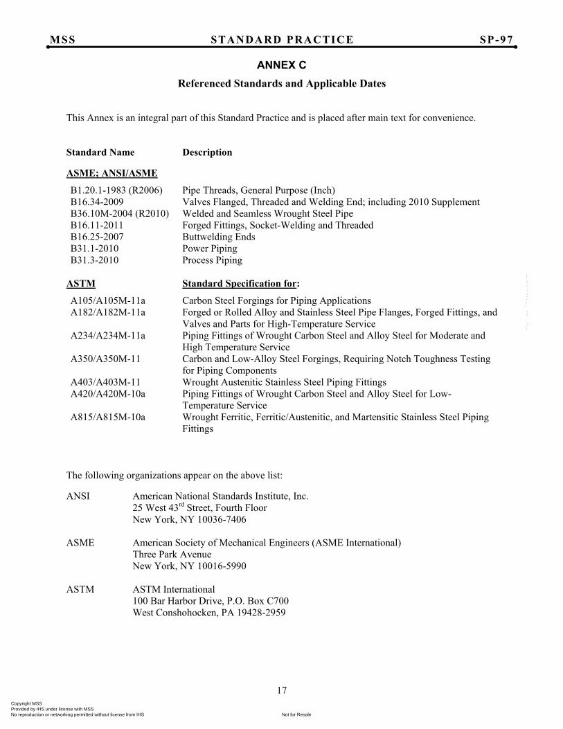
ANNEX C Referenced Standards and Applicable Dates
This Annex is an integral part of this Standard Practice and is placed after main text for convenience. Standard Name Description
ASME; ANSI/ASME
B1.20.1-1983 (R2006) Pipe Threads, General Purpose (Inch) B16.34-2009 Valves Flanged, Threaded and Welding End; including 2010 Supplement B36.10M-2004 (R2010) Welded and Seamless Wrought Steel Pipe B16.11-2011 Forged Fittings, Socket-Welding and Threaded B16.25-2007 Buttwelding Ends B31.1-2010 Power Piping B31.3-2010 Process Piping
ASTM Standard Specification for:
A105/A105M-11a Carbon Steel Forgings for Piping Applications A182/A182M-11a Forged or Rolled Alloy and Stainless Steel Pipe Flanges, Forged Fittings, and
Valves and Parts for High-Temperature Service A234/A234M-11a Piping Fittings of Wrought Carbon Steel and Alloy Steel for Moderate and
High Temperature Service A350/A350M-11 Carbon and Low-Alloy Steel Forgings, Requiring Notch Toughness Testing
for Piping Components A403/A403M-11 Wrought Austenitic Stainless Steel Piping Fittings A420/A420M-10a Piping Fittings of Wrought Carbon Steel and Alloy Steel for Low-
Temperature Service A815/A815M-10a Wrought Ferritic, Ferritic/Austenitic, and Martensitic Stainless Steel Piping
Fittings The following organizations appear on the above list:
ANSI American National Standards Institute, Inc. 25 West 43rd Street, Fourth Floor New York, NY 10036-7406 ASME American Society of Mechanical Engineers (ASME International) Three Park Avenue
New York, NY 10016-5990 ASTM ASTM International 100 Bar Harbor Drive, P.O. Box C700 West Conshohocken, PA 19428-2959
Copyright MSS Provided by IHS under license with MSS
Not for ResaleNo reproduction or networking permitted without license from IHS
--`,,```,,,,````-`-`,,`,,`,`,,`---
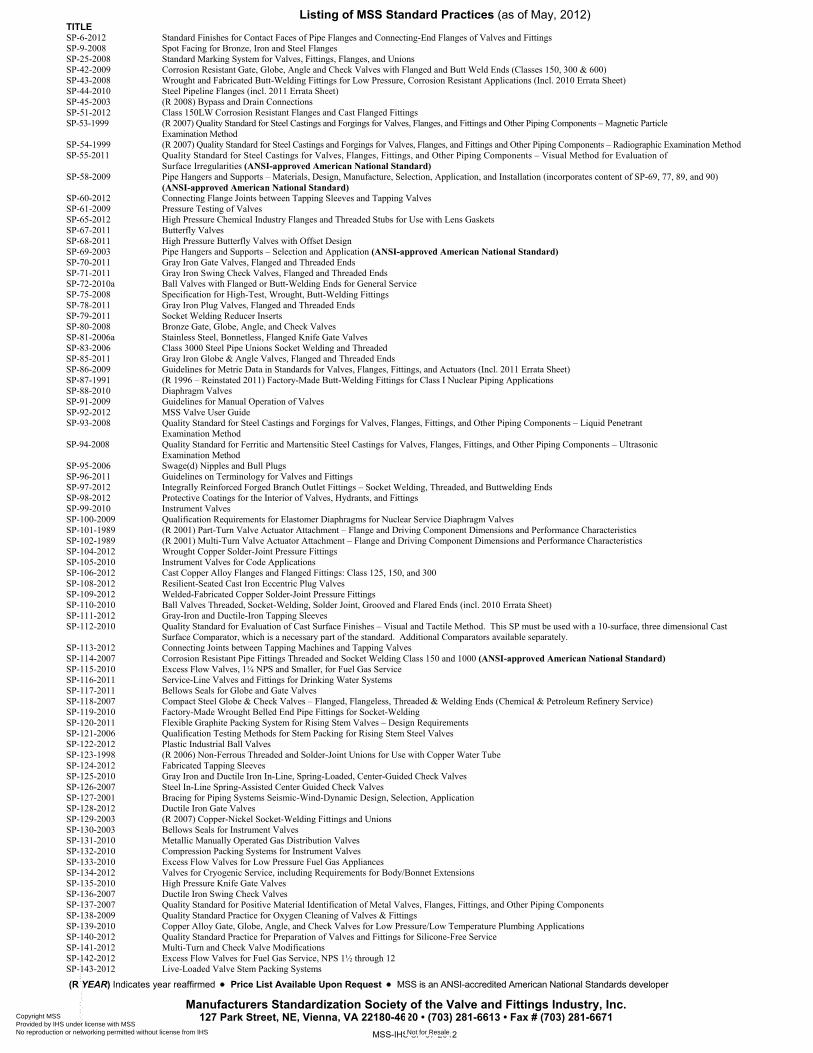
Listing of MSS Standard Practices (as of May, 2012) TITLE SP-6-2012 Standard Finishes for Contact Faces of Pipe Flanges and Connecting-End Flanges of Valves and Fittings SP-9-2008 Spot Facing for Bronze, Iron and Steel Flanges SP-25-2008 Standard Marking System for Valves, Fittings, Flanges, and Unions SP-42-2009 Corrosion Resistant Gate, Globe, Angle and Check Valves with Flanged and Butt Weld Ends (Classes 150, 300 & 600) SP-43-2008 Wrought and Fabricated Butt-Welding Fittings for Low Pressure, Corrosion Resistant Applications (Incl. 2010 Errata Sheet) SP-44-2010 Steel Pipeline Flanges (incl. 2011 Errata Sheet) SP-45-2003 (R 2008) Bypass and Drain Connections SP-51-2012 Class 150LW Corrosion Resistant Flanges and Cast Flanged Fittings SP-53-1999 (R 2007) Quality Standard for Steel Castings and Forgings for Valves, Flanges, and Fittings and Other Piping Components – Magnetic Particle Examination Method SP-54-1999 (R 2007) Quality Standard for Steel Castings and Forgings for Valves, Flanges, and Fittings and Other Piping Components – Radiographic Examination Method SP-55-2011 Quality Standard for Steel Castings for Valves, Flanges, Fittings, and Other Piping Components – Visual Method for Evaluation of Surface Irregularities (ANSI-approved American National Standard) SP-58-2009 Pipe Hangers and Supports – Materials, Design, Manufacture, Selection, Application, and Installation (incorporates content of SP-69, 77, 89, and 90) (ANSI-approved American National Standard) SP-60-2012 Connecting Flange Joints between Tapping Sleeves and Tapping Valves SP-61-2009 Pressure Testing of Valves SP-65-2012 High Pressure Chemical Industry Flanges and Threaded Stubs for Use with Lens Gaskets SP-67-2011 Butterfly Valves SP-68-2011 High Pressure Butterfly Valves with Offset Design SP-69-2003 Pipe Hangers and Supports – Selection and Application (ANSI-approved American National Standard) SP-70-2011 Gray Iron Gate Valves, Flanged and Threaded Ends SP-71-2011 Gray Iron Swing Check Valves, Flanged and Threaded Ends SP-72-2010a Ball Valves with Flanged or Butt-Welding Ends for General Service SP-75-2008 Specification for High-Test, Wrought, Butt-Welding Fittings SP-78-2011 Gray Iron Plug Valves, Flanged and Threaded Ends SP-79-2011 Socket Welding Reducer Inserts SP-80-2008 Bronze Gate, Globe, Angle, and Check Valves SP-81-2006a Stainless Steel, Bonnetless, Flanged Knife Gate Valves SP-83-2006 Class 3000 Steel Pipe Unions Socket Welding and Threaded SP-85-2011 Gray Iron Globe & Angle Valves, Flanged and Threaded Ends SP-86-2009 Guidelines for Metric Data in Standards for Valves, Flanges, Fittings, and Actuators (Incl. 2011 Errata Sheet) SP-87-1991 (R 1996 – Reinstated 2011) Factory-Made Butt-Welding Fittings for Class I Nuclear Piping Applications SP-88-2010 Diaphragm Valves SP-91-2009 Guidelines for Manual Operation of Valves SP-92-2012 MSS Valve User Guide SP-93-2008 Quality Standard for Steel Castings and Forgings for Valves, Flanges, Fittings, and Other Piping Components – Liquid Penetrant Examination Method SP-94-2008 Quality Standard for Ferritic and Martensitic Steel Castings for Valves, Flanges, Fittings, and Other Piping Components – Ultrasonic Examination Method SP-95-2006 Swage(d) Nipples and Bull Plugs SP-96-2011 Guidelines on Terminology for Valves and Fittings SP-97-2012 Integrally Reinforced Forged Branch Outlet Fittings – Socket Welding, Threaded, and Buttwelding Ends SP-98-2012 Protective Coatings for the Interior of Valves, Hydrants, and Fittings SP-99-2010 Instrument Valves SP-100-2009 Qualification Requirements for Elastomer Diaphragms for Nuclear Service Diaphragm Valves SP-101-1989 (R 2001) Part-Turn Valve Actuator Attachment – Flange and Driving Component Dimensions and Performance Characteristics SP-102-1989 (R 2001) Multi-Turn Valve Actuator Attachment – Flange and Driving Component Dimensions and Performance Characteristics SP-104-2012 Wrought Copper Solder-Joint Pressure Fittings SP-105-2010 Instrument Valves for Code Applications SP-106-2012 Cast Copper Alloy Flanges and Flanged Fittings: Class 125, 150, and 300 SP-108-2012 Resilient-Seated Cast Iron Eccentric Plug Valves SP-109-2012 Welded-Fabricated Copper Solder-Joint Pressure Fittings SP-110-2010 Ball Valves Threaded, Socket-Welding, Solder Joint, Grooved and Flared Ends (incl. 2010 Errata Sheet) SP-111-2012 Gray-Iron and Ductile-Iron Tapping Sleeves SP-112-2010 Quality Standard for Evaluation of Cast Surface Finishes – Visual and Tactile Method. This SP must be used with a 10-surface, three dimensional Cast
Surface Comparator, which is a necessary part of the standard. Additional Comparators available separately. SP-113-2012 Connecting Joints between Tapping Machines and Tapping Valves SP-114-2007 Corrosion Resistant Pipe Fittings Threaded and Socket Welding Class 150 and 1000 (ANSI-approved American National Standard) SP-115-2010 Excess Flow Valves, 1¼ NPS and Smaller, for Fuel Gas Service SP-116-2011 Service-Line Valves and Fittings for Drinking Water Systems SP-117-2011 Bellows Seals for Globe and Gate Valves SP-118-2007 Compact Steel Globe & Check Valves – Flanged, Flangeless, Threaded & Welding Ends (Chemical & Petroleum Refinery Service) SP-119-2010 Factory-Made Wrought Belled End Pipe Fittings for Socket-Welding SP-120-2011 Flexible Graphite Packing System for Rising Stem Valves – Design Requirements SP-121-2006 Qualification Testing Methods for Stem Packing for Rising Stem Steel Valves SP-122-2012 Plastic Industrial Ball Valves SP-123-1998 (R 2006) Non-Ferrous Threaded and Solder-Joint Unions for Use with Copper Water Tube SP-124-2012 Fabricated Tapping Sleeves SP-125-2010 Gray Iron and Ductile Iron In-Line, Spring-Loaded, Center-Guided Check Valves SP-126-2007 Steel In-Line Spring-Assisted Center Guided Check Valves SP-127-2001 Bracing for Piping Systems Seismic-Wind-Dynamic Design, Selection, Application SP-128-2012 Ductile Iron Gate Valves SP-129-2003 (R 2007) Copper-Nickel Socket-Welding Fittings and Unions SP-130-2003 Bellows Seals for Instrument Valves SP-131-2010 Metallic Manually Operated Gas Distribution Valves SP-132-2010 Compression Packing Systems for Instrument Valves SP-133-2010 Excess Flow Valves for Low Pressure Fuel Gas Appliances SP-134-2012 Valves for Cryogenic Service, including Requirements for Body/Bonnet Extensions SP-135-2010 High Pressure Knife Gate Valves SP-136-2007 Ductile Iron Swing Check Valves SP-137-2007 Quality Standard for Positive Material Identification of Metal Valves, Flanges, Fittings, and Other Piping Components SP-138-2009 Quality Standard Practice for Oxygen Cleaning of Valves & Fittings SP-139-2010 Copper Alloy Gate, Globe, Angle, and Check Valves for Low Pressure/Low Temperature Plumbing Applications SP-140-2012 Quality Standard Practice for Preparation of Valves and Fittings for Silicone-Free Service SP-141-2012 Multi-Turn and Check Valve Modifications SP-142-2012 Excess Flow Valves for Fuel Gas Service, NPS 1½ through 12 SP-143-2012 Live-Loaded Valve Stem Packing Systems
(R YEAR) Indicates year reaffirmed • Price List Available Upon Request • MSS is an ANSI-accredited American National Standards developer
Manufacturers Standardization Society of the Valve and Fittings Industry, Inc. 127 Park Street, NE, Vienna, VA 22180-4620 • (703) 281-6613 • Fax # (703) 281-6671
MSS-IHS SP-97-2012
Copyright MSS Provided by IHS under license with MSS
Not for ResaleNo reproduction or networking permitted without license from IHS
--`,,```,,,,````-`-`,,`,,`,`,,`---
![INTEGRALLY CLOSED SUBRINGS OF AN INTEGRAL DOMAIN · Hence if R is an integrally closed domain, then R + A[{XA}] is integrally closed if and only if A = \/A. In the remainder of this](https://img.pdfslide.net/doc/110x75/5cfc3e2388c993fe058b83e7/integrally-closed-subrings-of-an-integral-hence-if-r-is-an-integrally-closed.jpg)