Embed Size (px)
Citation preview

Integrated Amplifier
M-150 USER’S MANUAL
version 1.3

2
RESEARCH, INNOVATE, CREATE
“Whenever I speak about my company I speak with the passion we have. Located in the Paris region of France, I have ensured that Micromega has the best ele-
ments of my industrial group at their availability. In an age where music is dematerializing, we are committed to staying at the forefront of technology and growing
under our ‘made in France’ banner.
The M-one programme, with its incredible audio quality, technical capacity and sleek design represents a major advance in the history of our company. The result
of three years of research by our team, we are proud to introduce to you what we believe is the most effective and complete integrated stereo amplifier of its kind.
Micromega is synonymous with technological advances, expertise, reliability and sound clarity. All of our products reflect these demands.”
Didier HAMDI, CEO Micromega
The advantages of the M-One amplifier series :
• High quality, A/B class amplification
• Resonant power supply
• Symmetrical design
• Asahi Kasei AK4490 DAC converter
• Acoustic correction in situ using ROOM EQ
• Binaural processing of the headphone output
• Cover and remote control machined from aluminium block
• Android and iOS compatible control app
3 TABLE OF CONTENTS
1 - OVERVIEW ..............................................................................................4
1.1 Front and top ........................................................................................ 4
1.2 Back .......................................................................................................... 5
1.3 Sides (ventilation) ............................................................................... 6
1.4 Bottom .................................................................................................... 7
1.5 Infrared remote control ..................................................................... 8
1.5 Changing the IR Remote battery ................................................... 9
2 - CONNECTIONS .............................................................................................. 10
2.1 Phono input for a vinly turntable ................................................... 10
2.2 RCA line input ...................................................................................... 11
2.3 Balanced XLR analogue input ......................................................... 12
2.4 Coaxial digital input ............................................................................ 13
2.5 Optical digital input ............................................................................. 14
2.6 AES-EBU input ...................................................................................... 15
2.7 USB input (Type B) ............................................................................ 16
2.8 Bluetooth aptX connection .............................................................. 17
2.9 I²S input .................................................................................................. 19
2.10 LAN connection ................................................................................... 20
2.11 Speaker connections .......................................................................... 21
2.12 Connecting headphones .................................................................. 22
2.13 Subwoofer output ............................................................................... 23
2.14 Pre-out .................................................................................................... 24
2.15 Trigger sockets ...................................................................................... 25
2.16 Mains power supply ........................................................................... 26
2.17 Fuse .......................................................................................................... 27
3 - USER GUIDE ................................................................................................... 28
3.1 Starting up ............................................................................................. 28
3.2 Choosing your source ........................................................................ 29
3.3 Ajusting the balance ........................................................................... 30
3.4 Ajusting sensitivity .............................................................................. 31
3.5 Renaming the sources ........................................................................ 32
3.6 Updating the M-150 ............................................................................ 33
3.7 Updating the network module .................................................... ... 34
4 - SPECIFICATIONS .......................................................................................... 35
4 OVERVIEW
1 . 1 Front and top
The M-150 amplifier has two displays so that it can be controlled from any position. The displays will automatically adjust to whichever position the amplifier is in (e.g. flat, attached to wall).
There is a headphone socket on the front so that you can listen to your music in complete peace. A “Binaural” process (as an option) allows you to re-create the 3D sound scene through the headphones which is lost in classic stereophonic recordings.
On the top of the device are 4 buttons which you can use to adjust the reactions of your amplifier (see section 3.1 for more information).
Carefully check that the packaging is intact. If you feel it may have been tampered with or damaged please contact your vendor.
Carefully remove your device from the packaging. Store the packaging in a secure, dry place: if you need to return your device to the vendor you will require the original packaging.
1 . Overview
5 OVERVIEW
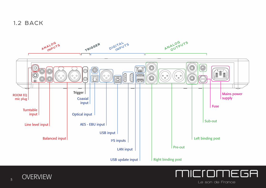
1 .2 BACK
Line level input
analog
inputs
digital
inputs
analog
outputs
trigger
Turntableinput
ROOM EQmic plug
Balanced input
Coaxial input
AES - EBU input
Optical input
USB input
I²S inputs
LAN input
USB update input
Left binding post
Pre-out
Sub-out
Right binding post
Fuse
Mains power supply
Trigger
6 OVERVIEW
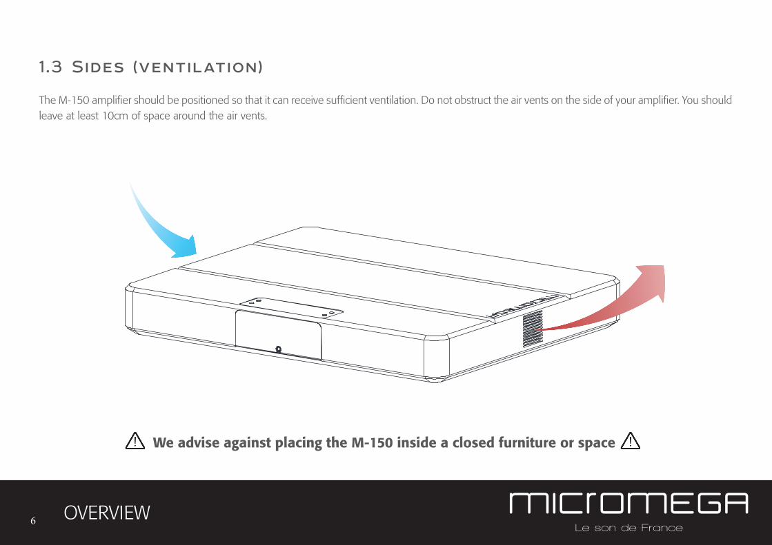
1 .3 Sides (ventilation)
The M-150 amplifier should be positioned so that it can receive sufficient ventilation. Do not obstruct the air vents on the side of your amplifier. You should leave at least 10cm of space around the air vents.
We advise against placing the M-150 inside a closed furniture or space

7 OVERVIEW
1 .4 Bottom
You will find a connection guide under your M-150 amplifier which illustrates all of the input and ouput terminals available.
Do not try to open the M-150
It contains potentially
life-threatening high voltage
MIC
GND
PHONO
L
++
RL
R
LINE BALANCEDT RIGCOAX
LANBT
RIGHT
PRE OUTSPEAKER OUT
SUB OUT
5x20 FUSE
10A SLOW-BLOW85-265 Vac / 47-63 Hz
AC MAINS
LEFT
OPTO AES
USB 2
1
IN
OUT
MM/MC I 2S1 I 2S2
Take note that the M-150 has spiked feets. It can harm your furniture. Use the included rubber pads to avoid damage.

8 OVERVIEW
1 .5 Infrared remote control
ON / OFF Mute
Change display size
Ajust volume
Input selector
« Bluetooth Connect »
- Press and release : pairing will start- Press and hold (for 10 seconds then release) : clear Bluetooth memory
9 OVERVIEW
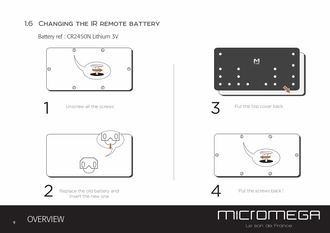
42
31
Replace the old battery andinsert the new one
Unscrew all the screws
Put the screws back !
Put the top cover back
1.6 Changing the IR remote battery
Battery ref : CR2450N Lithium 3V
10
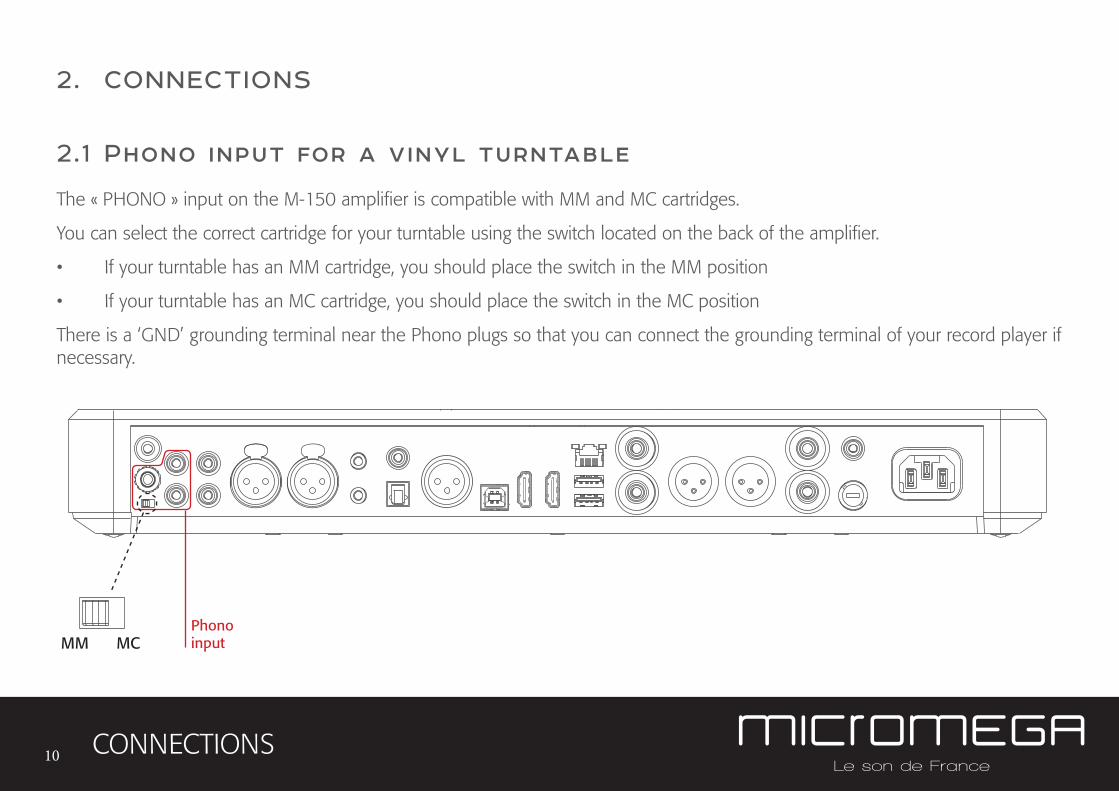
2.1 Phono input for a vinyl turntable
The « PHONO » input on the M-150 amplifier is compatible with MM and MC cartridges.
You can select the correct cartridge for your turntable using the switch located on the back of the amplifier.
• If your turntable has an MM cartridge, you should place the switch in the MM position
• If your turntable has an MC cartridge, you should place the switch in the MC position
There is a ‘GND’ grounding terminal near the Phono plugs so that you can connect the grounding terminal of your record player if necessary.
CONNECTIONS
Phonoinput
2. CONNECTIONS
MM MC
11
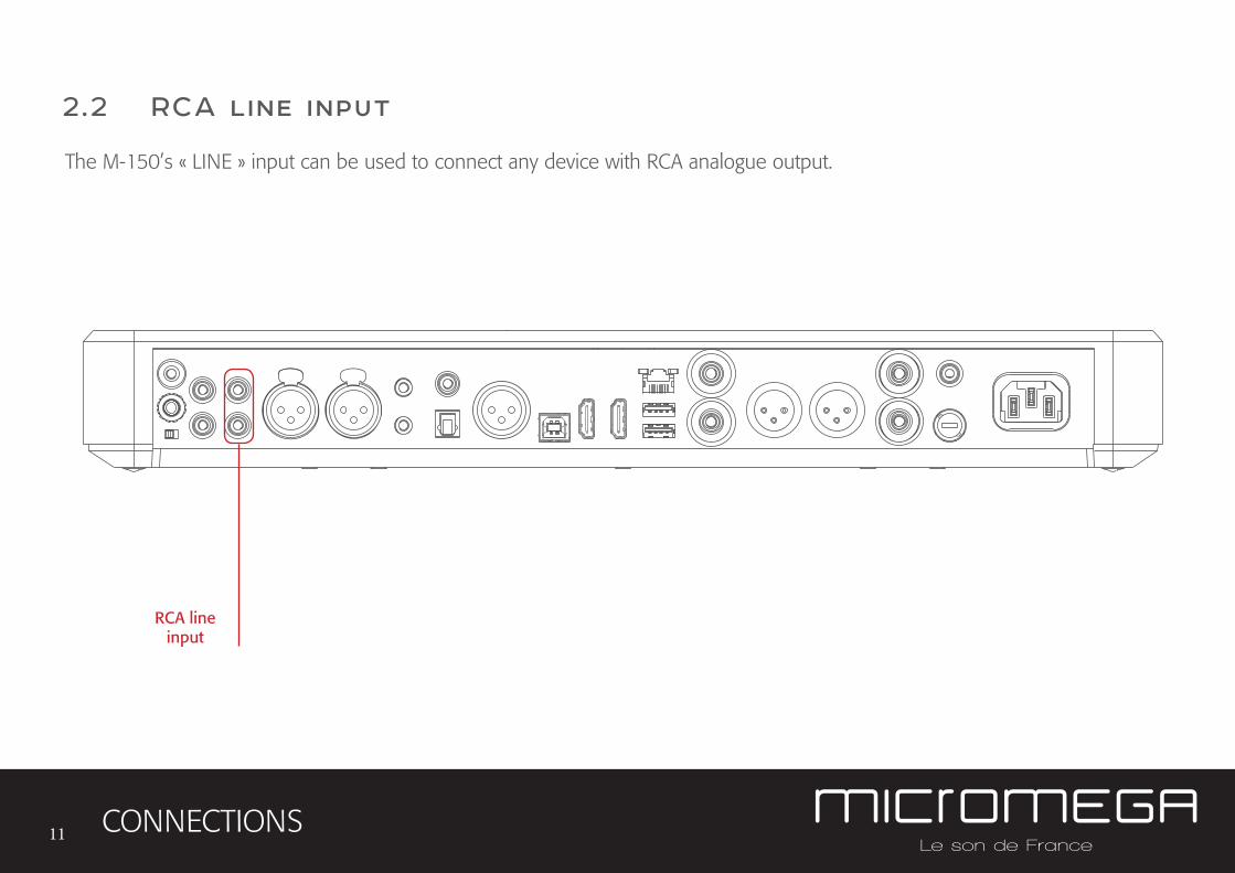
2.2 RCA line input
The M-150’s « LINE » input can be used to connect any device with RCA analogue output.
CONNECTIONS
RCA lineinput
12
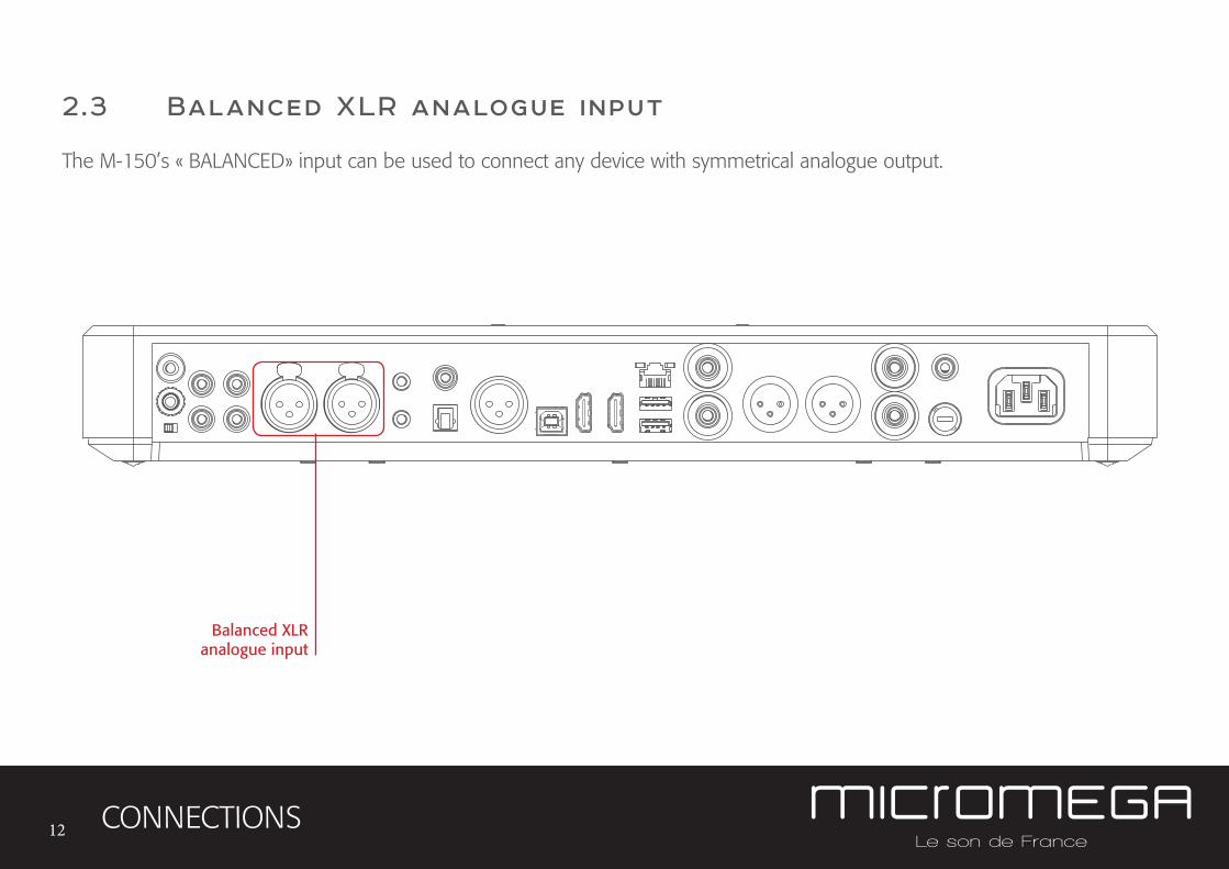
2.3 Balanced XLR analogue input
The M-150’s « BALANCED» input can be used to connect any device with symmetrical analogue output.
CONNECTIONS
Balanced XLRanalogue input
13
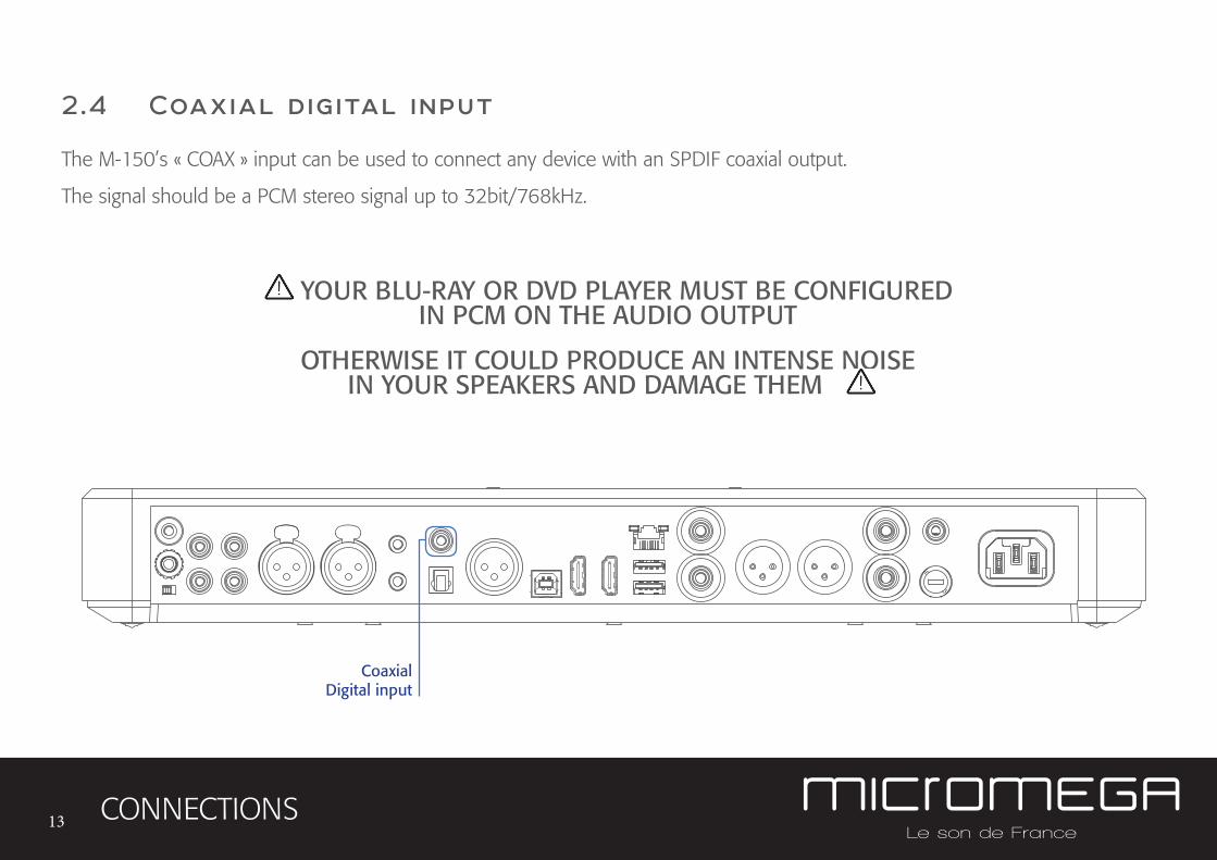
2.4 Coaxial digital input
The M-150’s « COAX » input can be used to connect any device with an SPDIF coaxial output.
The signal should be a PCM stereo signal up to 32bit/768kHz.
CONNECTIONS
CoaxialDigital input
YOUR BLU-RAY OR DVD PLAYER MUST BE CONFIGURED IN PCM ON THE AUDIO OUTPUT
OTHERWISE IT COULD PRODUCE AN INTENSE NOISE IN YOUR SPEAKERS AND DAMAGE THEM
14
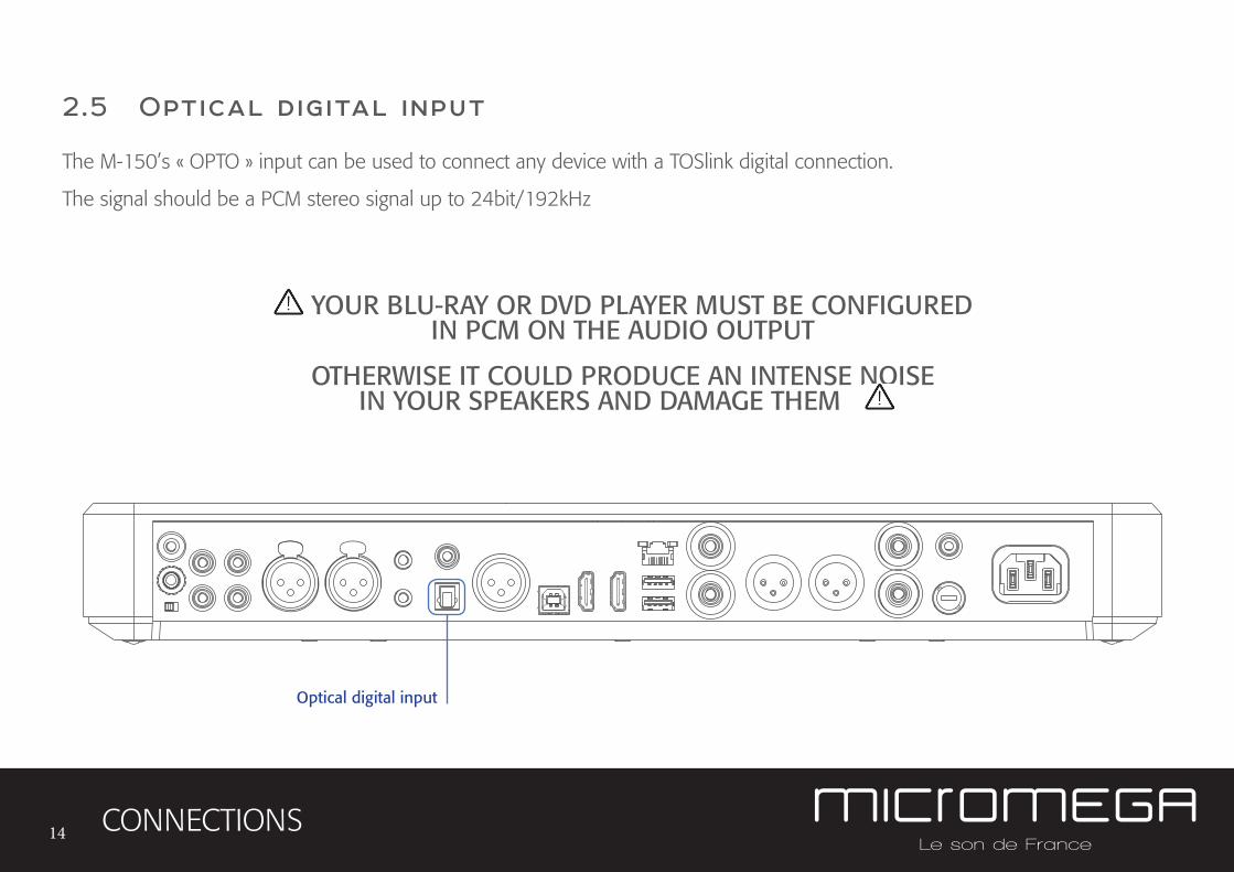
2.5 Optical digital input
The M-150’s « OPTO » input can be used to connect any device with a TOSlink digital connection.
The signal should be a PCM stereo signal up to 24bit/192kHz
CONNECTIONS
Optical digital input
YOUR BLU-RAY OR DVD PLAYER MUST BE CONFIGURED IN PCM ON THE AUDIO OUTPUT
OTHERWISE IT COULD PRODUCE AN INTENSE NOISE IN YOUR SPEAKERS AND DAMAGE THEM
15
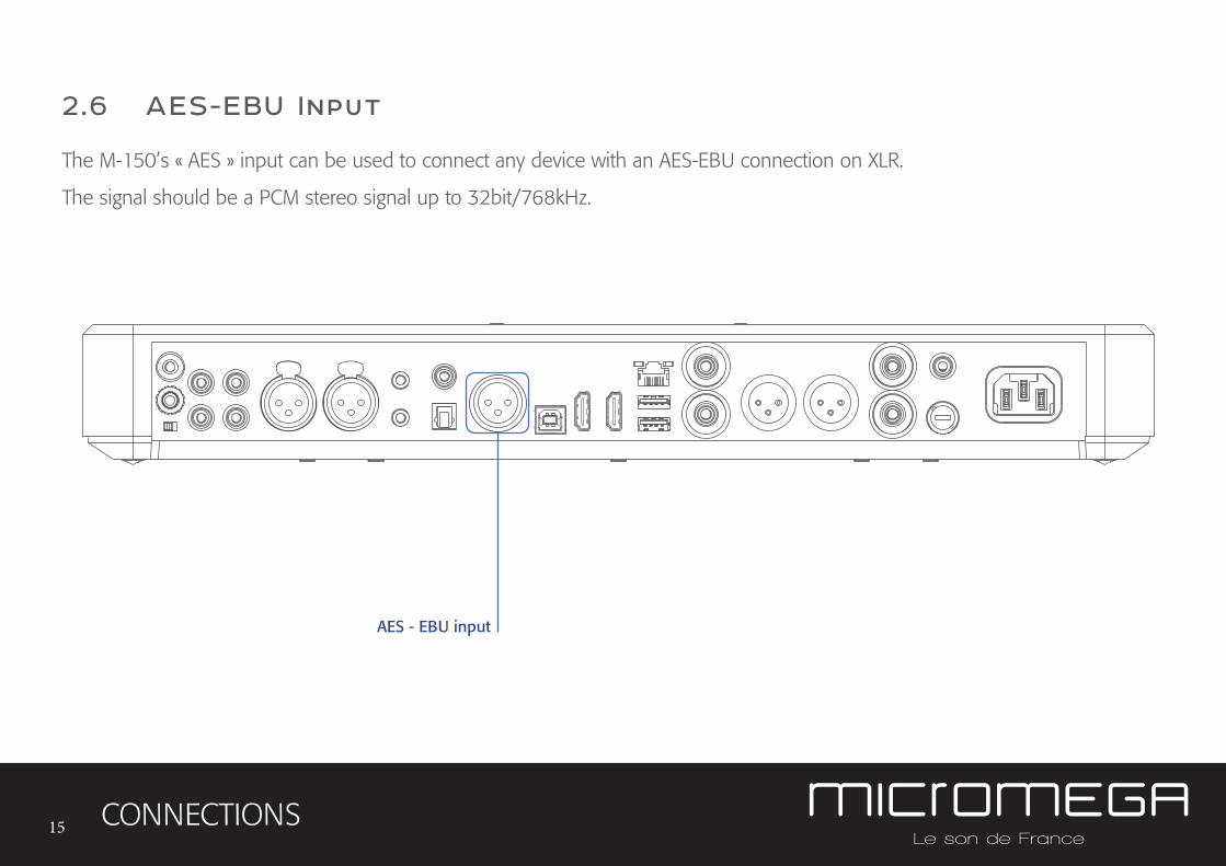
2.6 AES-EBU Input
The M-150’s « AES » input can be used to connect any device with an AES-EBU connection on XLR.
The signal should be a PCM stereo signal up to 32bit/768kHz.
CONNECTIONS
AES - EBU input
16
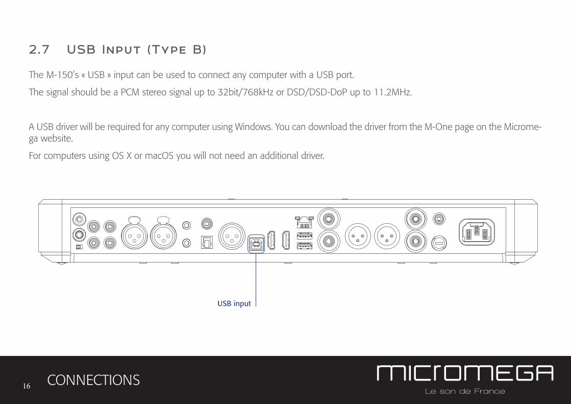
2.7 USB Input (Type B)
The M-150’s « USB » input can be used to connect any computer with a USB port.
The signal should be a PCM stereo signal up to 32bit/768kHz or DSD/DSD-DoP up to 11.2MHz.
A USB driver will be required for any computer using Windows. You can download the driver from the M-One page on the Microme-ga website.
For computers using OS X or macOS you will not need an additional driver.
CONNECTIONS
USB input
17
2.8 Bluetooth® aptX® connection
The M-150’s « BT » connection can be used to wirelessly connect smartphones, tablets, computers or MP3 players with Bluetooth®. The Bluetooth® link is compatible with aptX® for the best sound quality. To make this manual easier to read, the term « Smartphone » will be used in this section to mean smartphones, tablets, computers and MP3 players.
To connect via Bluetooth® for the first time:
• Ensure that the Bluetooth® function on your smartphone is turned on.
• Use the remote control to click on the ‘BT’ button.
• You should see the « M-ONE » appear on the list of Bluetooth® connections available on your smartphone. To establish a connection select the « M-ONE ».
• Launch music on your smartphone.
To connect via Bluetooth® with a different smartphone, tablet etc.
• Ensure that the Bluetooth® function on your smartphone is turned on.
• Use the remote control to click on the ‘BT’ button.
• Then press release the « BTC » button on the remote control.
• You should see the « M-ONE » appear on the list of Bluetooth® connections available on your smartphone. To establish a connection select the « M-ONE ».
• Launch play on your smartphone.
CONNECTIONS
18
The following time you select the BT input :
• If the Bluetooth® on your smartphone is turned on, the connection will work automatically once you select the ‘BT’ button on the amplifier using the remote.
NB : Bluetooth® is a « point to point » connection. This means that if a tablet is already connected to the amplifier, you will not be able to connect your smartphone at the same time. You will need to disconnect your tablet from the amplifier before connecting your smartphone.
CONNECTIONS
19
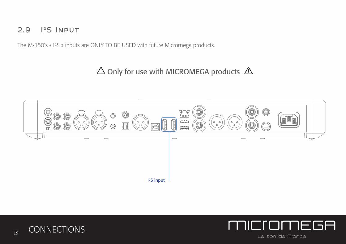
2.9 I ²S Input
The M-150’s « I²S » inputs are ONLY TO BE USED with future Micromega products.
CONNECTIONS
I²S input
Only for use with MICROMEGA products
20
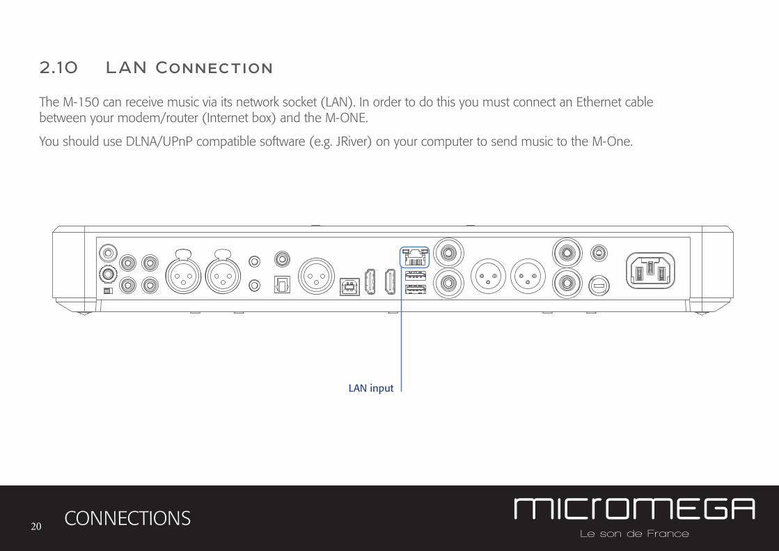
2.10 LAN Connection
The M-150 can receive music via its network socket (LAN). In order to do this you must connect an Ethernet cable between your modem/router (Internet box) and the M-ONE.
You should use DLNA/UPnP compatible software (e.g. JRiver) on your computer to send music to the M-One.
CONNECTIONS
LAN input
21
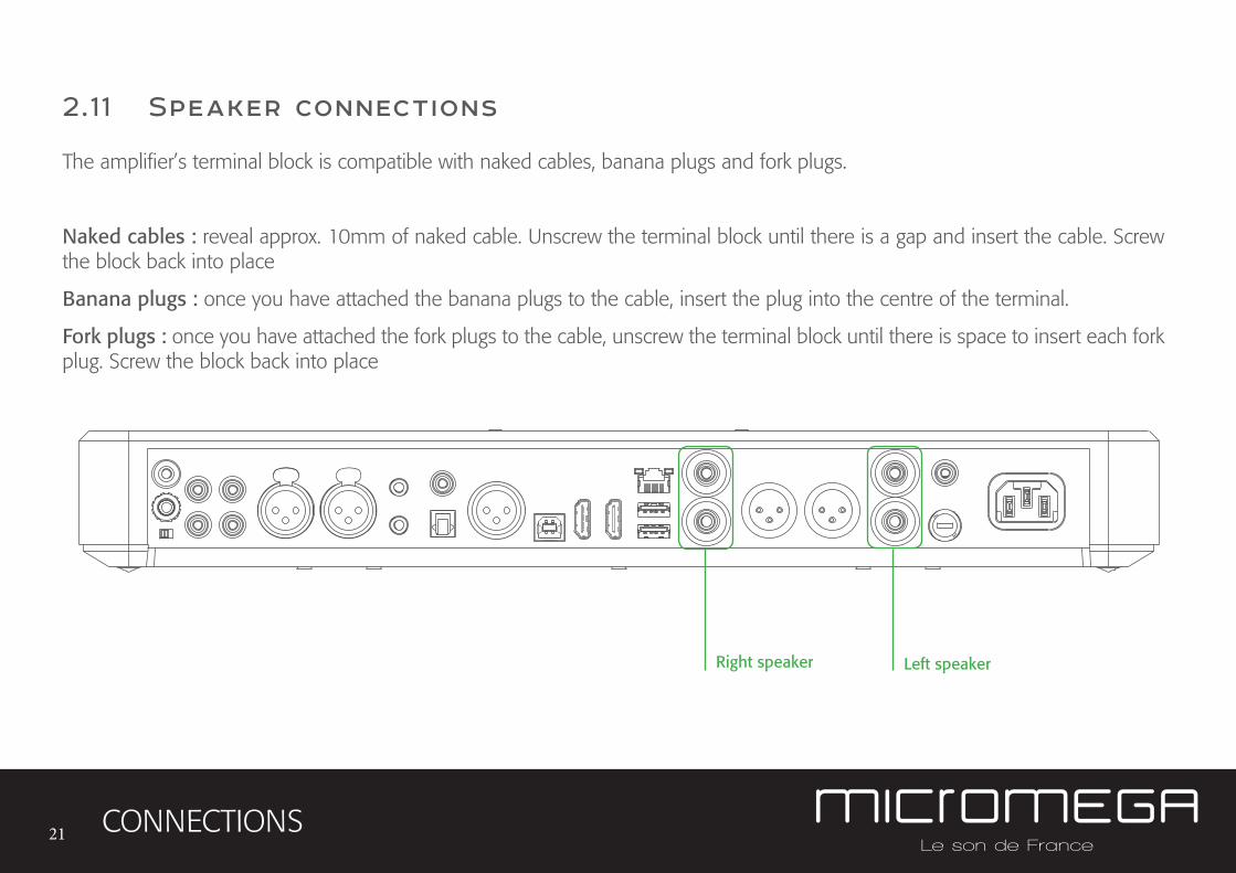
2.1 1 Speaker connections
The amplifier’s terminal block is compatible with naked cables, banana plugs and fork plugs.
Naked cables : reveal approx. 10mm of naked cable. Unscrew the terminal block until there is a gap and insert the cable. Screw the block back into place
Banana plugs : once you have attached the banana plugs to the cable, insert the plug into the centre of the terminal.
Fork plugs : once you have attached the fork plugs to the cable, unscrew the terminal block until there is space to insert each fork plug. Screw the block back into place
CONNECTIONS
Left speakerRight speaker
22
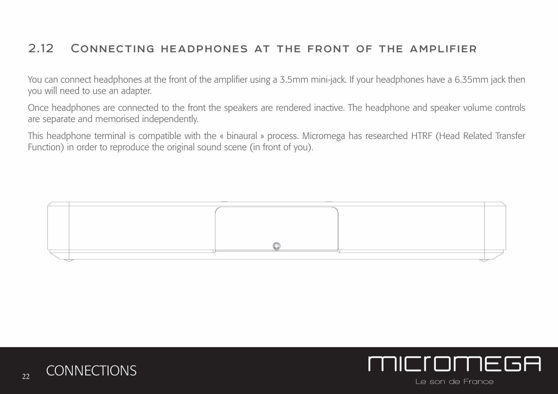
2.12 Connecting headphones at the front of the amplifier
CONNECTIONS
You can connect headphones at the front of the amplifier using a 3.5mm mini-jack. If your headphones have a 6.35mm jack then you will need to use an adapter.
Once headphones are connected to the front the speakers are rendered inactive. The headphone and speaker volume controls are separate and memorised independently.
This headphone terminal is compatible with the « binaural » process. Micromega has researched HTRF (Head Related Transfer Function) in order to reproduce the original sound scene (in front of you).
23
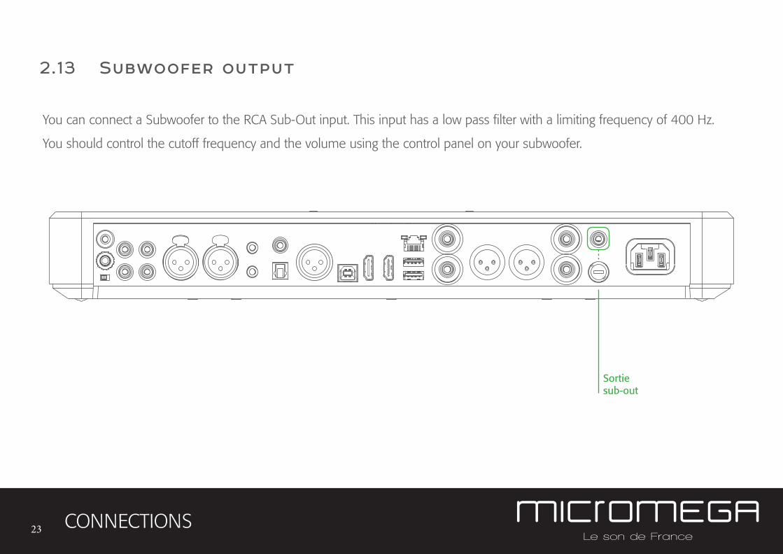
2.13 Subwoofer output
CONNECTIONS
Sortiesub-out
You can connect a Subwoofer to the RCA Sub-Out input. This input has a low pass filter with a limiting frequency of 400 Hz.
You should control the cutoff frequency and the volume using the control panel on your subwoofer.
24
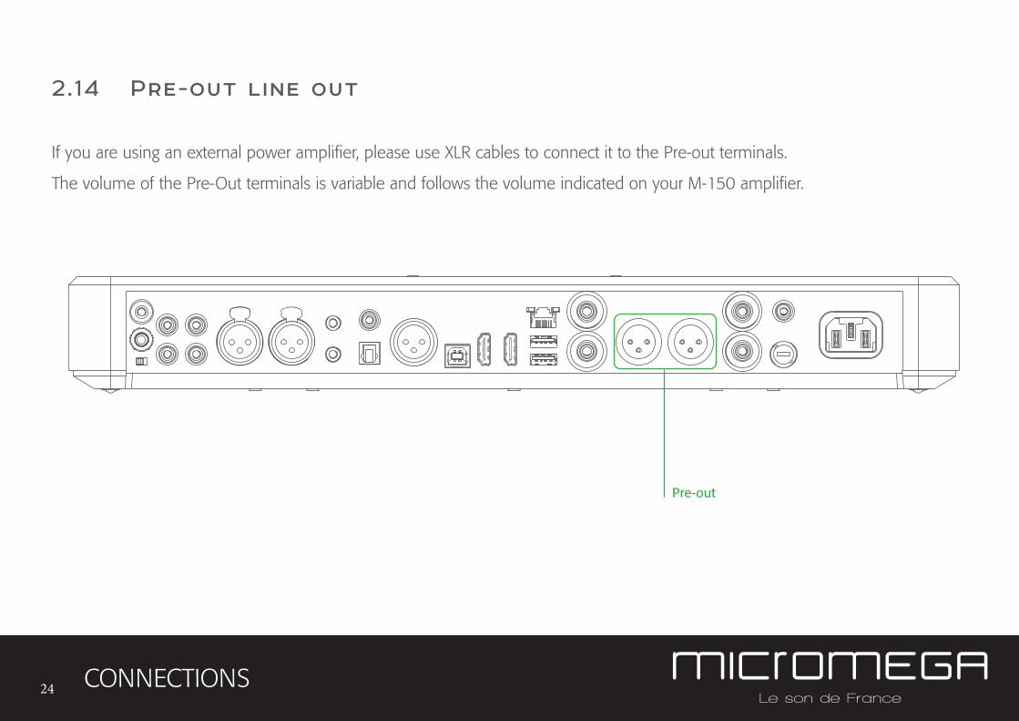
2.14 Pre-out line out
CONNECTIONS
Pre-out
If you are using an external power amplifier, please use XLR cables to connect it to the Pre-out terminals.
The volume of the Pre-Out terminals is variable and follows the volume indicated on your M-150 amplifier.
25
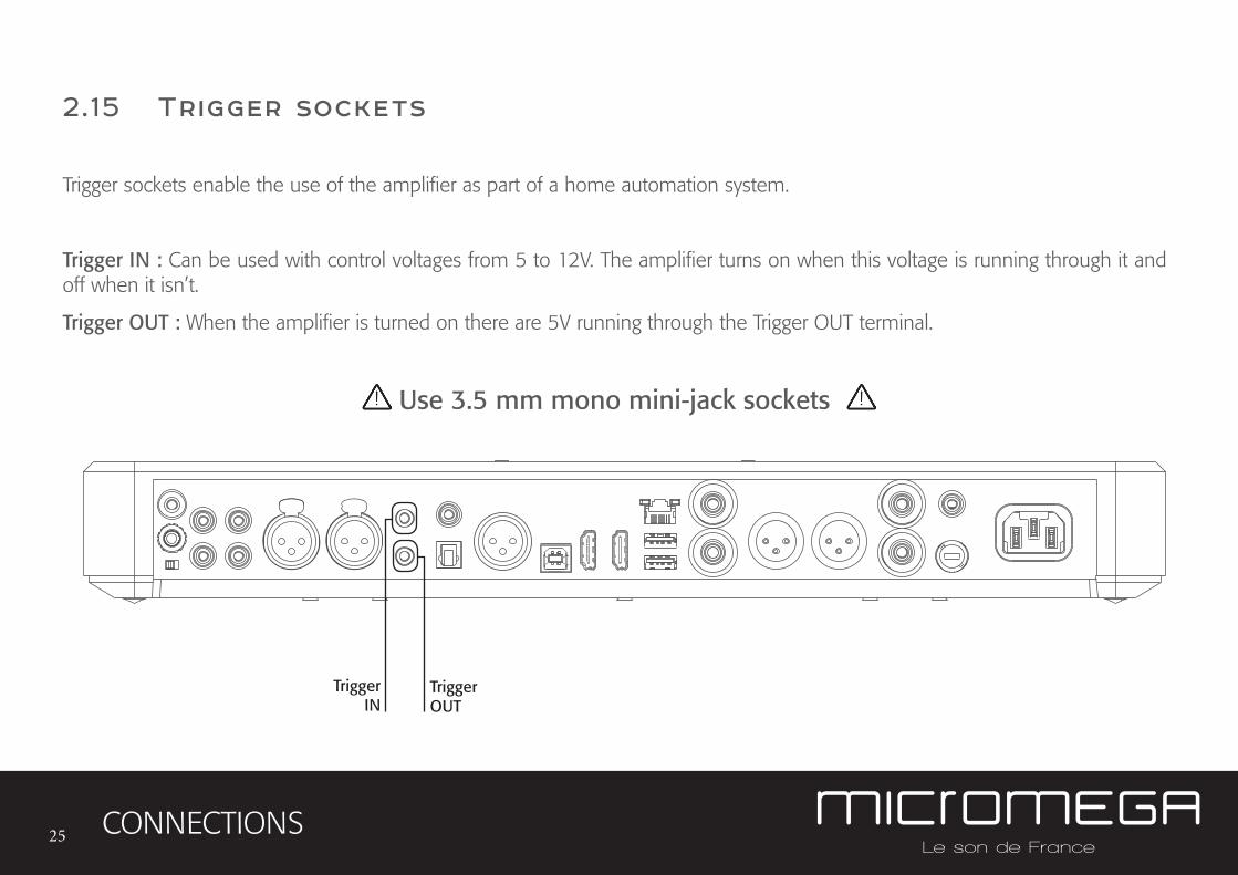
2.15 Trigger sockets
CONNECTIONS
Trigger sockets enable the use of the amplifier as part of a home automation system.
Trigger IN : Can be used with control voltages from 5 to 12V. The amplifier turns on when this voltage is running through it and off when it isn’t.
Trigger OUT : When the amplifier is turned on there are 5V running through the Trigger OUT terminal.
TriggerIN
TriggerOUT
Use 3.5 mm mono mini-jack sockets
26
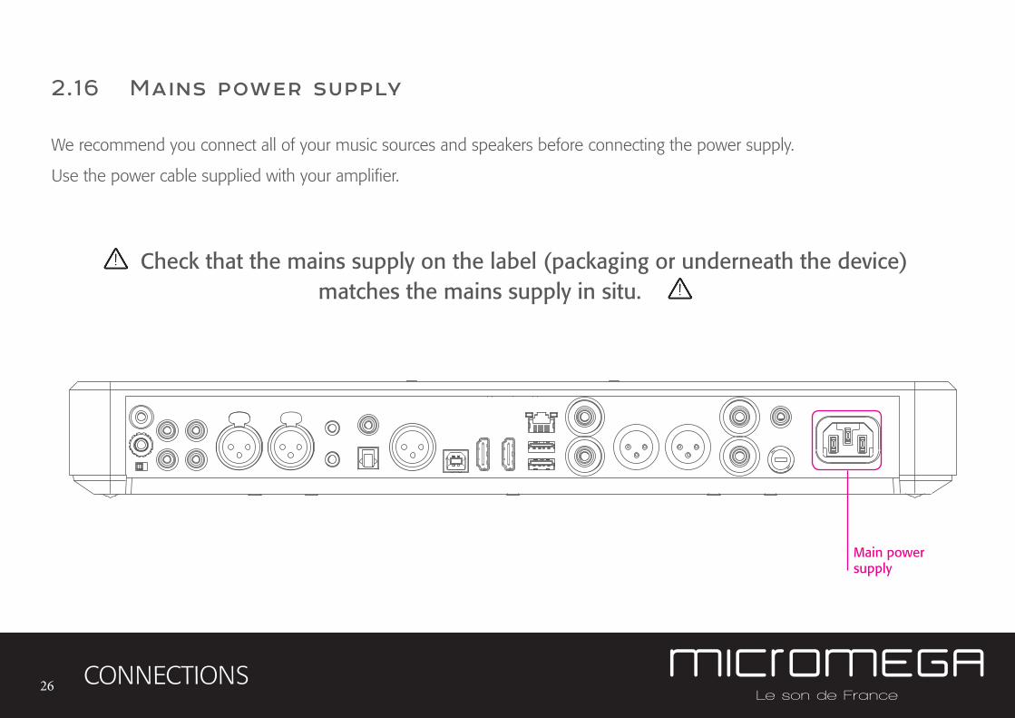
2.16 Mains power supply
CONNECTIONS
Main power supply
We recommend you connect all of your music sources and speakers before connecting the power supply.
Use the power cable supplied with your amplifier.
Check that the mains supply on the label (packaging or underneath the device) matches the mains supply in situ.
27
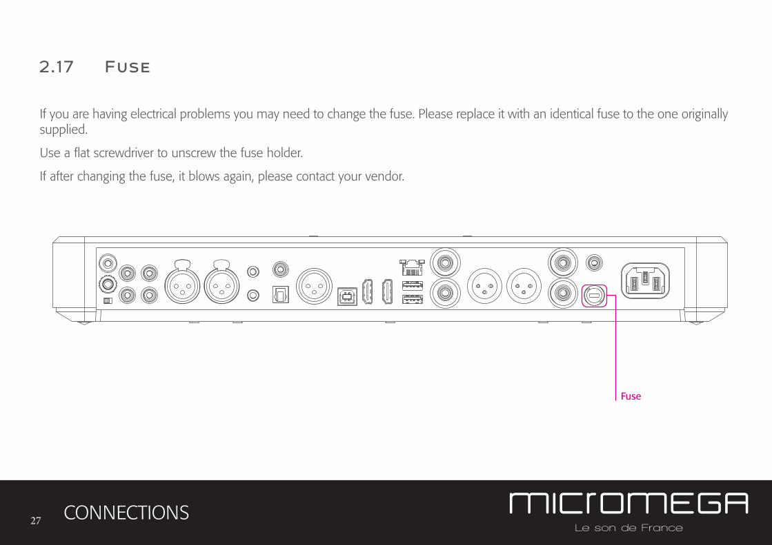
2.17 Fuse
CONNECTIONS
Fuse
If you are having electrical problems you may need to change the fuse. Please replace it with an identical fuse to the one originally supplied.
Use a flat screwdriver to unscrew the fuse holder.
If after changing the fuse, it blows again, please contact your vendor.
28
3. User Guide
USER GUIDE
3.1 Starting up
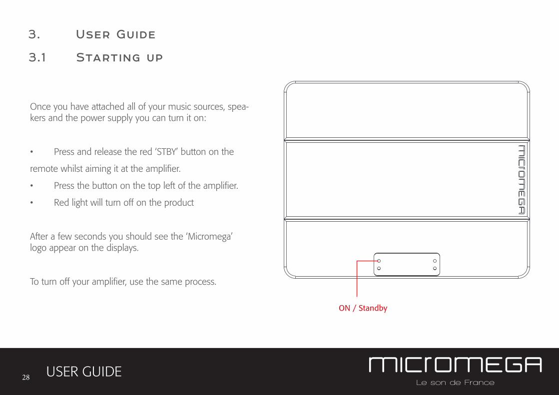
Once you have attached all of your music sources, spea-kers and the power supply you can turn it on:
• Press and release the red ‘STBY’ button on the
remote whilst aiming it at the amplifier.
• Press the button on the top left of the amplifier.
• Red light will turn off on the product
After a few seconds you should see the ‘Micromega’ logo appear on the displays.
To turn off your amplifier, use the same process.
ON / Standby
29
3.2 Choosing your source
USER GUIDE
USB AES<
OK
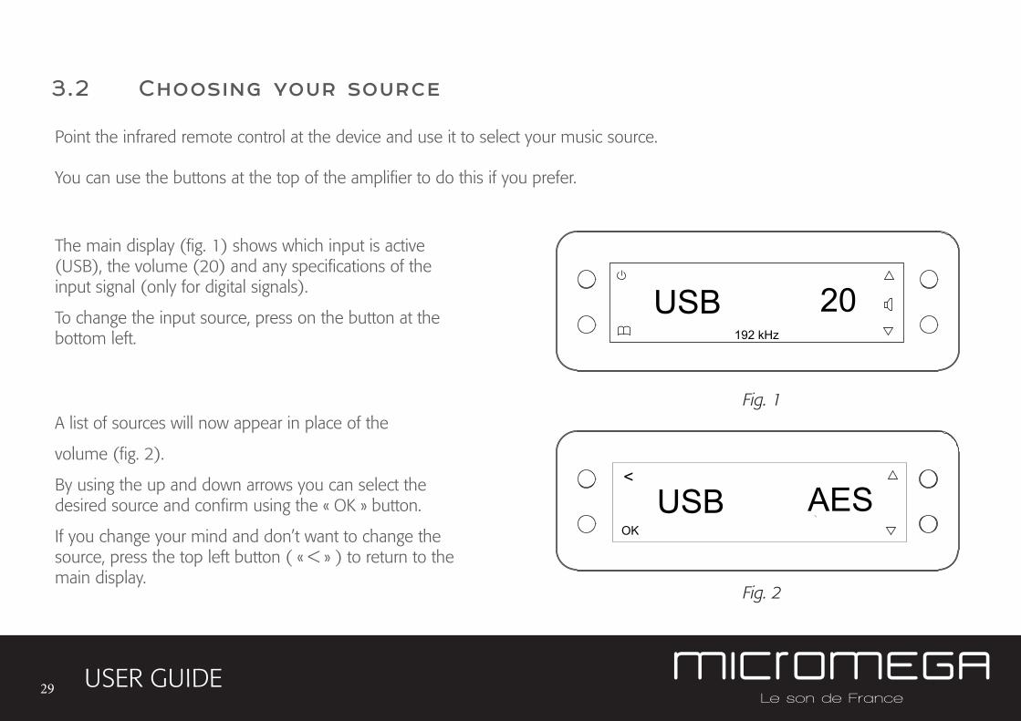
The main display (fig. 1) shows which input is active (USB), the volume (20) and any specifications of the input signal (only for digital signals).
To change the input source, press on the button at the bottom left.
A list of sources will now appear in place of the
volume (fig. 2).
By using the up and down arrows you can select the desired source and confirm using the « OK » button.
If you change your mind and don’t want to change the source, press the top left button ( « < » ) to return to the main display.
Fig. 1
Fig. 2
Point the infrared remote control at the device and use it to select your music source.
You can use the buttons at the top of the amplifier to do this if you prefer.
USB 20192 kHz
30
3.3 Adjusting the balance
USER GUIDE
USB BAL<
OK
Fig. 1
Fig. 2
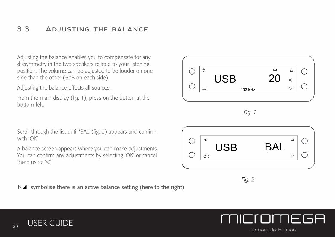
Adjusting the balance enables you to compensate for any dissymmetry in the two speakers related to your listening position. The volume can be adjusted to be louder on one side than the other (6dB on each side).
Adjusting the balance effects all sources.
From the main display (fig. 1), press on the button at the bottom left.
Scroll through the list until ‘BAL’ (fig. 2) appears and confirm with ‘OK’
A balance screen appears where you can make adjustments. You can confirm any adjustments by selecting ‘OK’ or cancel them using ‘<’.
symbolise there is an active balance setting (here to the right)
USB 20192 kHz
31
3.4 Adjusting sensitivity
USER GUIDE
Fig. 1
Fig. 2
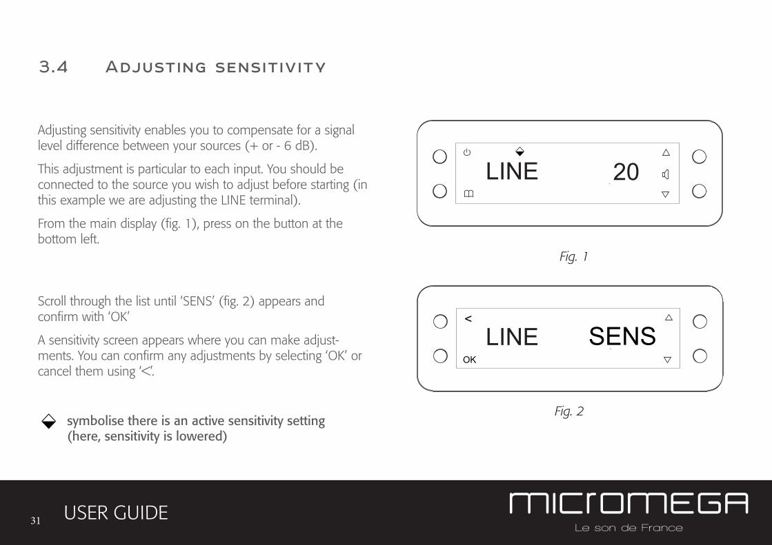
Adjusting sensitivity enables you to compensate for a signal level difference between your sources (+ or - 6 dB).
This adjustment is particular to each input. You should be connected to the source you wish to adjust before starting (in this example we are adjusting the LINE terminal).
From the main display (fig. 1), press on the button at the bottom left.
Scroll through the list until ‘SENS’ (fig. 2) appears and confirm with ‘OK’
A sensitivity screen appears where you can make adjust-ments. You can confirm any adjustments by selecting ‘OK’ or cancel them using ‘<’.
SENS<
OK
symbolise there is an active sensitivity setting (here, sensitivity is lowered)
LINE 20
LINE
32
3.5 Renaming the sources
USER GUIDE
20
Fig. 1
Fig. 2
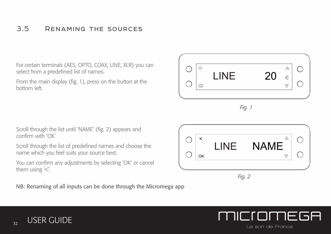
For certain terminals (AES, OPTO, COAX, LINE, XLR) you can select from a predefined list of names.
From the main display (fig. 1), press on the button at the bottom left.
Scroll through the list until ‘NAME’ (fig. 2) appears and confirm with ‘OK’
Scroll through the list of predefined names and choose the name which you feel suits your source best.
You can confirm any adjustments by selecting ‘OK’ or cancel them using ‘<’.
NAME<
OK
LINE
LINE
NB: Renaming of all inputs can be done through the Micromega app
33
3.6 Updating the M-150
USER GUIDE
Fig. 1
Fig. 2
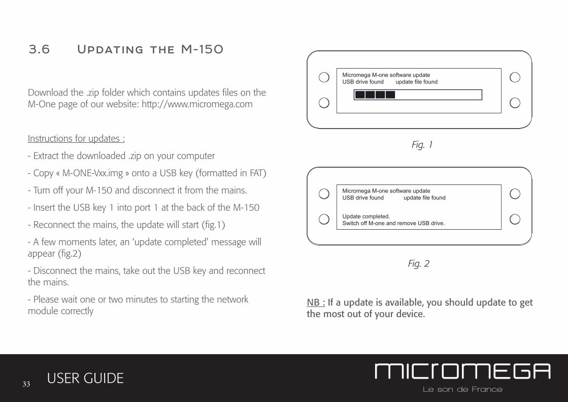
Download the .zip folder which contains updates files on the M-One page of our website: http://www.micromega.com
Instructions for updates :
- Extract the downloaded .zip on your computer
- Copy « M-ONE-Vxx.img » onto a USB key (formatted in FAT)
- Turn off your M-150 and disconnect it from the mains.
- Insert the USB key 1 into port 1 at the back of the M-150
- Reconnect the mains, the update will start (fig.1)
- A few moments later, an ‘update completed’ message will appear (fig.2)
- Disconnect the mains, take out the USB key and reconnect the mains.
- Please wait one or two minutes to starting the network module correctly
Micromega M-one software updateUSB drive found update file found
Micromega M-one software updateUSB drive found update file found
Update completed.Switch off M-one and remove USB drive.
NB : If a update is available, you should update to get the most out of your device.
34
3.7 Updating the network module
USER GUIDE
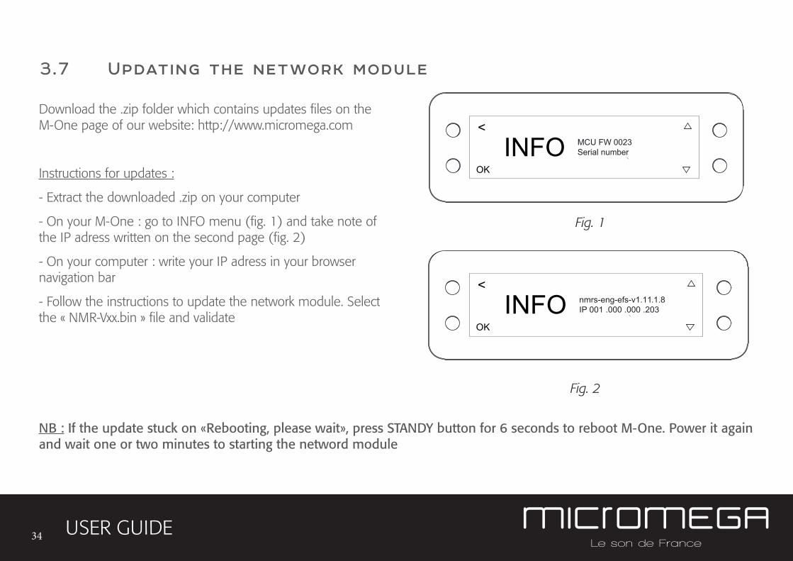
Download the .zip folder which contains updates files on the M-One page of our website: http://www.micromega.com
Instructions for updates :
- Extract the downloaded .zip on your computer
- On your M-One : go to INFO menu (fig. 1) and take note of the IP adress written on the second page (fig. 2)
- On your computer : write your IP adress in your browser navigation bar
- Follow the instructions to update the network module. Select the « NMR-Vxx.bin » file and validate
Fig. 1
Fig. 2
<
OK
INFO MCU FW 0023Serial number
<
OK
INFO nmrs-eng-efs-v1.11.1.8IP 001 .000 .000 .203
NB : If the update stuck on «Rebooting, please wait», press STANDY button for 6 seconds to reboot M-One. Power it again and wait one or two minutes to starting the netword module
35
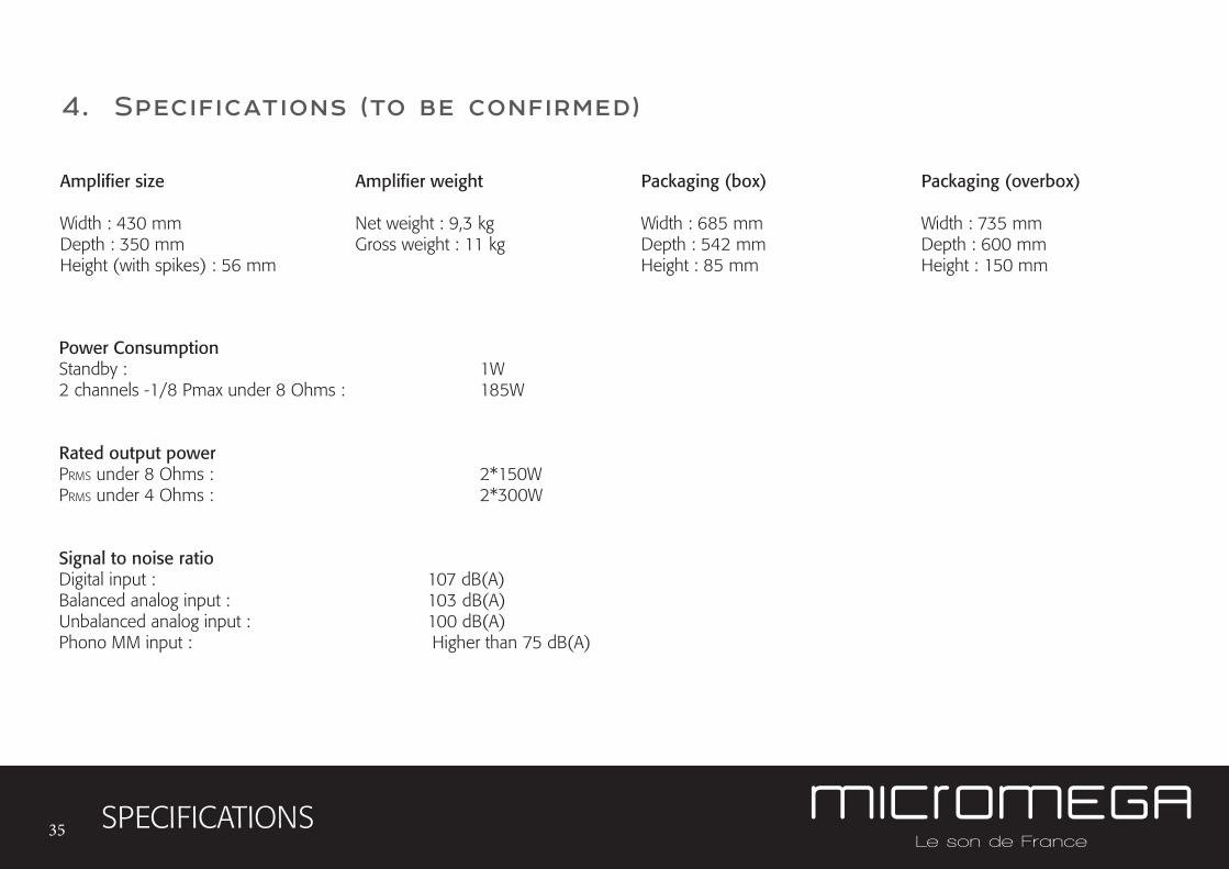
4. Specifications (to be confirmed)
SPECIFICATIONS
Amplifier size
Width : 430 mmDepth : 350 mmHeight (with spikes) : 56 mm
Amplifier weight
Net weight : 9,3 kgGross weight : 11 kg
Packaging (overbox)
Width : 735 mmDepth : 600 mmHeight : 150 mm
Packaging (box)
Width : 685 mmDepth : 542 mmHeight : 85 mm
Power Consumption Standby : 1W2 channels -1/8 Pmax under 8 Ohms : 185W
Rated output power PRMS under 8 Ohms : 2*150WPRMS under 4 Ohms : 2*300W
Signal to noise ratioDigital input : 107 dB(A)Balanced analog input : 103 dB(A)Unbalanced analog input : 100 dB(A)Phono MM input : Higher than 75 dB(A)
36 SPECIFICATIONS
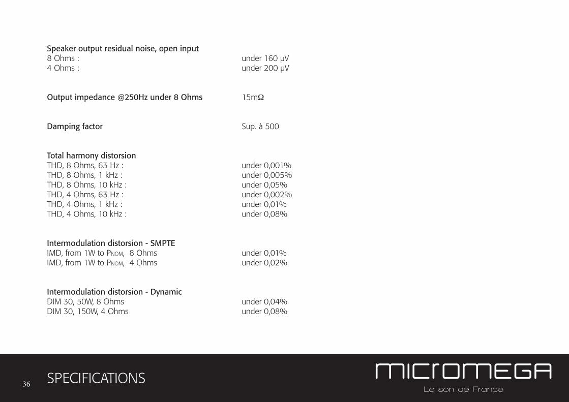
Speaker output residual noise, open input 8 Ohms : under 160 µV4 Ohms : under 200 µV
Output impedance @250Hz under 8 Ohms 15mΩ
Damping factor Sup. à 500
Total harmony distorsion THD, 8 Ohms, 63 Hz : under 0,001%THD, 8 Ohms, 1 kHz : under 0,005%THD, 8 Ohms, 10 kHz : under 0,05%THD, 4 Ohms, 63 Hz : under 0,002%THD, 4 Ohms, 1 kHz : under 0,01%THD, 4 Ohms, 10 kHz : under 0,08%
Intermodulation distorsion - SMPTE IMD, from 1W to PNOM, 8 Ohms under 0,01%IMD, from 1W to PNOM, 4 Ohms under 0,02%
Intermodulation distorsion - DynamicDIM 30, 50W, 8 Ohms under 0,04%DIM 30, 150W, 4 Ohms under 0,08%
37 SPECIFICATIONS
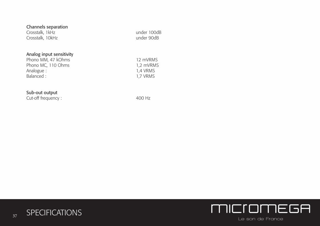
Channels separation Crosstalk, 1kHz under 100dBCrosstalk, 10kHz under 90dB
Analog input sensitivityPhono MM, 47 kOhms 12 mVRMSPhono MC, 110 Ohms 1,2 mVRMSAnalogue : 1,4 VRMSBalanced : 1,7 VRMS
Sub-out output Cut-off frequency : 400 Hz

AUDIS MICROMEGA
13-15 rue du 8 Mai 1945
94470 Boissy-Saint-Léger
FRANCE
version 1.3
FRANCE
paris
http://www.micromega.com
http://facebook.com/micromegahifi