Embed Size (px)
Citation preview

1
The Future of Gas Turbine Technology
7th
International Gas Turbine Conference
14-15 October 2014, Brussels, Belgium
Paper ID Number (21)
INTEGRATED APPROACH TO GAS TURBINE ROTOR CONDITION ASSESSMENT AND
LIFE MANAGEMENT
John Scheibel/Electric Power Research Institute
3420 Hillview Avenue; Palo Alto, California, USA
650.855.2446
V. P. ‘Swami’ Swaminathan/TurboMet International
8026 Winter Park, San Antonio, Texas, USA
210-520-9030
Gil J Dean/ AccTTech, LLC
151 Tandem Drive ,Greer, South Carolina, USA
864-848-1602
ABSTRACT
Turbine manufacturers (OEM’s) place limits on the
service life of aging gas turbine (GT) rotors/discs based on
either the number of hours of operation or the number of
start-up cycles. These limits are based on design
calculations and maintenance conventions, but and seldom
fully factor in actual operational history of the individual
turbines. A significant number of gas turbine rotors are
either condemned or slated for replacement during a future
outage. Some turbines experience premature damage
resulting in the selective component replacements. EPRI
conducted metallurgical evaluation of retired discs to
understand the crack initiation and propagation
mechanisms as well as detailed structural engineering
analysis to understand damage root cause. Examples of
rotor condition and remaining life assessment studies
conducted are presented in this paper. INTRODUCTION AND BACKGROUND
Historically, GT rotor life was considered to have
many decades of useful life, consistent with a major
structural component of the unit. Unlike the routine repair
and replacement cycle for gas path and combustion
components, the rotor presents significant maintenance
issues for owners to ship large, heavy rotors to the limited
facilities capable of disassembly.
OEM's have now defined significantly shorter than the
original design life expectations or mandated periodic
major disassembly inspections for the rotor structure.
Premature rotor damage can result in large unplanned
costs associated with extended outages where spare rotors
are unavailable. OEM’s have issued several directives to
turbine owners about these problems and
recommendations. The full cost of an unexpected serious
rotor damage can exceed $10M with considerable
interruption to plant availability.
Since the rotor contains significant kinetic energy,
sudden failure of rotating components represents various
safety risks to personnel and equipment. An example of
the substantial shortfall in expected rotor lives is the GE F-
Class Stage 1 and stage 2 turbine wheel rim dovetail post
cracking shown by Figure 1. These failures can happen in
less than 50,000 hours and can cause additional millions of
dollars in collateral damage to the gas path components.
Other recent examples are the GE aft compressor rotor
dovetail cracking on both the E-Class and F-Class turbines,
resulting in a number of replacement Stage 17 compressor
wheels. The Siemens V-X4.X Class turbines have
similarly been identified to have significantly shorter lives
due to premature embrittlement of the 12Cr turbine
wheels. A failure incident related to compressor tie bolts
on the Siemens-Westinghouse 501F resulted in extensive
flowpath and rotor damage. The Alstom 11N's are also
experiencing early retirement or shop rework due to
turbine rotor life limiting design issues, such as the
cracking in the turbine L-bore cooling channel. However,
to date rotor damage has not resulted in outright
catastrophic failure and safety impacts.
2
Figure 1. Frame 7FA First Stage Rim Failure
Many utilities recognize the need for proactive actions
in life management of their fleet with safety, reliability and
cost benefit as their main concerns. Balancing these
aspects of the power plant management requires
consideration of the OEM recommendations as well as the
knowledge, expertise and technology available from
independent engineering service providers. The EPRI
rotor program has developed technology and methods to
offer an integrated approach to gas turbine rotor condition
assessment and life management. These methods provide
turbine owners with an independent evaluation of
remaining life with a defined rotor-specific technical basis
ROTOR DAMAGE MECHANISMS AND END OF
LIFE
A significant level of variations exists in the
conditions between the compressor inlet to the turbine
outlet. The important variables that affect the damage
mechanisms are temperature, stress, humidity, other
external environmental variables such as the introduction
of steam or water for NOx control and power
augmentation, washing practices, use of chemicals,
variations in the fuel compositions, rotor internal cooling
configurations, stress concentration regions such as sharp
corners, the severity of start-stop practices and unexpected
trips. The potential and historically observed damage
mechanisms for the GT rotor are many There are several
categories of damage. The table below identifies the
escalating damage categories in gas turbine rotors.
Table 1. Damage Categories in Rotors
Various damage mechanisms are operative at the
different parts of the turbine as listed below:
Material property variations and service
degradation
Low cycle fatigue crack initiation in critical
locations
Creep damage in the higher temperature regions
Fretting and fretting fatigue damage at the rim
locations
High-cycle fatigue at the rim due to abnormal
vibration
Oxidation, wear and corrosion of sections and key
interfaces
Crack growth during service from initiation or
original defects
Reduced fracture tolerance due to material
embrittlement
Abnormal loading which exceed the design
parameters
Other effects such as damage by adjacent
structure or maintenance practices
Progressive mechanical damage due to improper
repair and assembly
A generalized map of some of the more common
damage mechanisms in gas turbine components are shown
in Figure 2. Depending on the location and the service
conditions, rotor and disc crack initiation and propagation
mechanisms may vary. On the compressor discs,
corrosion pitting, stress corrosion cracking, low-cycle
fatigue (LCF) crack initiation and growth, high-cycle
fatigue (HCF) cracking of the blade attachments may limit
the useable life. On the hot section turbine side the
damage mechanisms are creep crack initiation and growth,
low-cycle fatigue and thermal-fatigue (TMF) damage,
embrittlement, etc. Other damage mechanisms include rim
dovetail cracking due to excessive staking, flange cracking
due to both HCF and LCF, vibration due to rabbet / bolt
face slip, premature rabbet cracking, etc.
Figure 2. Some of the common damage mechanisms in
GT rotors
Within the same wheel/disc, the damage mechanisms
differ depending on the location. For example in a
compressor wheel, the near bore area is subjected to high
tangential and circumferential stresses. Even a relatively
small flaw located in the near bore region could
theoretically grow to critical crack size leading to rapid
3
brittle fracture during a cold start condition. At the
periphery blade attachment locations the failure
mechanisms could be high-cycle fatigue crack initiation
and propagation, corrosion pitting, crevice corrosion and
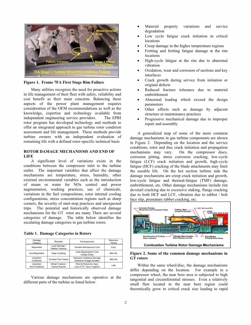
stress corrosion cracking. Examples of corrosion pitting
on a compressor disc and dovetail cracking is shown in
Figure 3.
Figure 3. Corrosion pitting of an IGT compressor disc
(top) and fluorescent particle indication of a crack at
blade attachment dovetail (bottom)
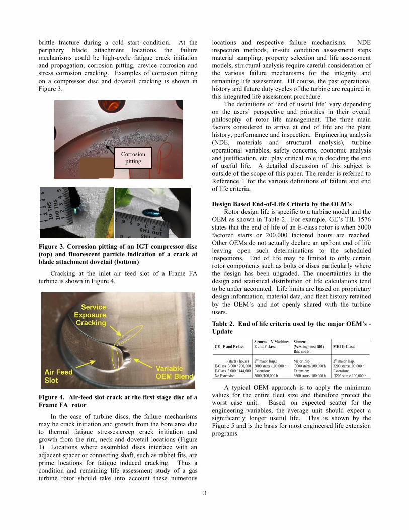
Cracking at the inlet air feed slot of a Frame FA
turbine is shown in Figure 4.
Figure 4. Air-feed slot crack at the first stage disc of a
Frame FA rotor
In the case of turbine discs, the failure mechanisms
may be crack initiation and growth from the bore area due
to thermal fatigue stresses:creep crack initiation and
growth from the rim, neck and dovetail locations (Figure
1) Locations where assembled discs interface with an
adjacent spacer or connecting shaft, such as rabbet fits, are
prime locations for fatigue induced cracking. Thus a
condition and remaining life assessment study of a gas
turbine rotor should take into account these numerous
locations and respective failure mechanisms. NDE
inspection methods, in-situ condition assessment steps
material sampling, property selection and life assessment
models, structural analysis require careful consideration of
the various failure mechanisms for the integrity and
remaining life assessment. Of course, the past operational
history and future duty cycles of the turbine are required in
this integrated life assessment procedure.
The definitions of ‘end of useful life’ vary depending
on the users’ perspective and priorities in their overall
philosophy of rotor life management. The three main
factors considered to arrive at end of life are the plant
history, performance and inspection. Engineering analysis
(NDE, materials and structural analysis), turbine
operational variables, safety concerns, economic analysis
and justification, etc. play critical role in deciding the end
of useful life. A detailed discussion of this subject is
outside of the scope of this paper. The reader is referred to
Reference 1 for the various definitions of failure and end
of life criteria.
Design Based End-of-Life Criteria by the OEM’s
Rotor design life is specific to a turbine model and the
OEM as shown in Table 2. For example, GE’s TIL 1576
states that the end of life of an E-class rotor is when 5000
factored starts or 200,000 factored hours are reached.
Other OEMs do not actually declare an upfront end of life
leaving open such determinations to the scheduled
inspections. End of life may be limited to only certain
rotor components such as bolts or discs particularly where
the design has been upgraded. The uncertainties in the
design and statistical distribution of life calculations tend
to be under accounted. Life limits are based on proprietary
design information, material data, and fleet history retained
by the OEM’s and not openly shared with the turbine
users.
Table 2. End of life criteria used by the major OEM’s -
Update
A typical OEM approach is to apply the minimum
values for the entire fleet size and therefore protect the worst case unit. Based on expected scatter for the
engineering variables, the average unit should expect a
significantly longer useful life. This is shown by the
Figure 5 and is the basis for most engineered life extension
programs.
GE - E and F class:
(starts / hours)
E-Class 5,000 / 200,000
F-Class 5,000 / 144,000
No Extension
Siemens - V Machines
E and F class:
2nd
major Insp.:
3000 starts /100,000 h
Extension:
3000 /100,000 h
Siemens -
(Westinghouse 501)
D/E and F:
Major Insp.:
3600 starts/100,000 h
Extension:
3600 starts/ 100,000 h
MHI G-Class:
2nd
major Insp.
3200 starts/100,000 h
Extension:
3200 starts/ 100,000 h
Corrosion
pitting

4
Figure 5. Normal life distribution curve and OEM’s
end of life definitions
For example, for the GE MS5001 class industrial gas
turbine has declared the useful life to be 5,000 factored
starts and 200,000 factored hours with up to one additional
50,000 factored hours interval based on disassembly and
inspection. These criteria are established for the E-class
rotors by GER-3620, TIL-1576 and ETC-068. GE
provides no additional service life beyond 5,000 factored
starts. The restrictions apply to both the compressor and
turbine rotors. Further, no starts based maintenance
factors is provided for rotors other than the F-Class. The
situation leaves turbine owners with the inability to
calculate factored starts. Consequently several GT owners
of E-class turbines confronting the 5,000 starts life limit
have taken it upon themselves to re-qualify the rotor for
extended service using independent resources.
MATERIAL DEGRADATION MECHANISMS AND
THEIR EFFECT ON ROTOR LIFE
There are several alloys used in the manufacturing of
gas turbines. Depending on the operating temperature and
environment various chemical compositions, heat
treatments and strengths are selected. Low alloy steels
such as 2-3.5NiCrMoV and 1CMoV steels are generally
applied to the compressor discs. For the hot end turbine
discs and built-up rotors, 1CrMoV, 12Cr alloys and in
some cases INCO alloys (IN-706 and IN-718) with
varying compositions are used by the US and European
manufacturers. When the rotor is exposed to the operating
environment and high-temperatures for a long time, the
rotor material properties will eventually degrade. It is
important to take into account such property degradation in
performing the remaining life assessment calculations.
Material vintage and cleanliness can have an influence on
the material properties and aging characteristics. The
extent of residual elements such as phosphorus, sulfur,
antimony and tin play important role in the embrittlement
susceptibility of the steels. Old vintage alloys (pre 1980)
are more susceptible due to higher impurity content. More
recent vintage rotor materials are cleaner and less
susceptible to this problem. Some of the material
degradation mechanisms as a result of service exposure are
listed below.
Metallurgical microstructural changes
Material softening and hardness decrease
Yield and tensile strength reduction
Creep strength decrease
Low-cycle fatigue strength reduction
Increase in crack growth rates leads to lower life
Increase in the ductile to brittle transition
temperature (fracture appearance transition
temperature, FATT)
Decrease in fracture toughness which results in
increased risk of brittle failure
One of the most reliable methods of obtaining material
properties is to conduct destructive sectioning of retired
rotors and discs and perform the various metallurgical and
mechanical tests to obtain the critical properties. EPRI has
acquired many such rotor discs after retirement and is
conducting various metallurgical and mechanical tests to
obtain the necessary data to apply in our life assessment
programs.
Properties obtained are tensile, Charpy impact
(FATT), fracture toughness, crack growth, low-cycle and
creep properties. Material tests from highly stressed
locations such as the fir tree posts were conducted to
investigate the presence or absence of local damage due to
long term service. Disc materials covering the full service
operating regime range from low hours/starts to high
hours (exceeding 300,000 hours) and high starts
(exceeding 5,000 starts) are evaluated and tested to obtain
material properties.
INTEGRATED ROTOR CONDITION AND LIFE
ASSESSMENT
An integrated approach which combines critical
engineering disciplines and plant operational history is
essential to conduct a pragmatic condition and remaining
life assessment of rotors. These four areas are illustrated in
Figure 6. All these four components are critical and play
equal importance in any rotor life assessment program.
Figure 6. Four critical disciplines of an integrated
condition and remaining life assessment program
Dimensions and Nondestructive Inspection
The dimensions of the rotor components undergo
changes during the life cycle of turbines. There are many
reasons both metallurgical and mechanical in nature
contributing to these changes over time. The dimensional
INSPECTION
(Dimensions & NDE)
STRUCTURAL ANALYSIS
STRESS AND TEMP.
(FEA)
OPERATING &
MAINTENANCE
HISTORY
FAILURE MODES,
MATERIAL
PROPERTIES & LIFE
PREDICTION MODELS
5
features of each component are characterized and models
prepared by computer aided design (CAD). The measured
dimensional features help to verify whether the critical
dimensional tolerances have deviated over time due to the
thermal stresses of the gas turbine that may operate in a
cyclic load. The dimensional measurements are performed
using coordinate measurement machines (CMM) and then
converted to CAD models. The accuracy with which this
activity is performed will affect the precision of the
subsequent structural integrity and remaining life
assessment evaluations. Some of these critical dimensions
are listed below.
A. Turbine Wheels – all stages – diameters, run-
outs and flatness are the critical dimensions
1. Rabbet fits
2. Bores
3. Bolt circle faces
4. Bolts and bolt holes
5. Bucket dovetail fit – measure and assess
stock loss from wear/corrosion
B. Turbine Spacers
1. Rabbet fits
2. Bores
3. Bolt circle faces
4. Bolt holes
5. Outer diameter seal features
Proper tooling with high accuracy and sensitivity are
used to measure these dimensions either in the field or at
an overhaul facility. Both contact and non contact systems
are used for this purpose.
Nondestructive Evaluation (NDE)
NDE is an integral part of any condition and remaining life
assessment program. We follow the general outline below:
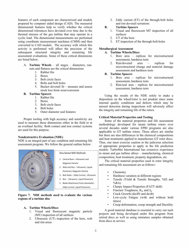
Figure 7. NDE methods used to evaluate the various
regions of a turbine disc
A. Turbine Wheels/Discs
1. Visual and fluorescent magnetic particle
(MT) inspection of all surfaces
2. Ultrasonic (UT) inspection of the bore, web
and rim areas
3. Eddy current (ET) of the through-bolt holes
and rim dovetail serrations
B. Turbine Spacers
1. Visual and fluorescent MT inspection of all
surfaces
2. UT of the bore
3. ET inspection of the through-bolt holes
Metallurgical Assessment
A. Turbine Wheels/Discs
1. Bore area – replicas for microstructural
assessment, hardness tests
2. Rim/dovetail area – replicas for
microstructural change and material damage
assessment and hardness tests
B. Turbine Spacers
1. Bore area - replicas for microstructural
assessment, hardness tests
2. Rim/seal area - replicas for microstructural
assessment, hardness tests
Using the results of the NDE solely to make a
disposition on the wheel/rotor is not prudent since some
internal quality conditions and defects which may be
missed detection during inspections will adversely affect
the integrity and remaining life of the rotors.
Critical Material Properties and Testing
Some of the material properties and life assessment
methodology developed for steam turbine rotors over
several decades under various EPRI programs are also
applicable to GT turbine rotors. These alloys are similar
but there are also differences in the chemical compositions
and heat treatments applied to manufacture GT rotor discs.
Thus, one must exercise caution in the judicious selection
of appropriate properties to apply in the life prediction
models. TurboMet International has extensive experience
in steam and gas turbine alloys – manufacturing, chemical
composition, heat treatment, property degradation, etc. The critical material properties used in rotor integrity
and remaining life assessment are as follows:
• Chemistry
• Hardness variation at different regions
• Tensile (Yield & Tensile Strengths, %El and
%RA)
• Charpy Impact Properties (FATT shift)
• Fracture Toughness, KIc and JIc
• Crack Growth (da/dN and da/dt)
• Low-cycle Fatigue (with and without hold
times)
• Creep deformation, creep strength and Ductility
A good material database is essential to carry out such
projects and being developed under this program from
retired discs as well as using miniature samples obtained
from discs in service
1
2
3
45
1
2
3
45
Disc/wheel NDE Methods
1. Central Bore – Ultrasonic and
Magnetic Particle
2. Web and Disc – Ultrasonic, Liquid
Penetrant, Magnetic Particle
3. Bolt Holes – Eddy Current, Ultrasonic
4. Rim - Ultrasonic, Liquid Penetrant
5. Blade Attachment Posts (dovetails) -
Eddy Current, Liquid Penetrant,
6
An example of miniature sample removal from a MS
5001 disc is shown in Figure 8.
.
Figure 8. Miniature surface scoop sampling from
MS5001 turbine discs for material condition and
property assessment
In the absence of such data, one assumes very
conservative properties which could lead to erroneous
recommendations. Many of these properties are a strong
function of temperature. Small specimen versus large
specimen property correlations are being established to
facilitate the extraction and use of miniature specimen to
obtain the necessary material properties from the actual
rotor being evaluated.
Life Prediction Methods and Algorithm
Since the rotors and discs have relatively large section
sizes, the total life of these components is determined by
both crack initiation and crack propagation lives. As
discussed previously, cracks may initiate under creep or
creep-fatigue, low-cycle fatigue or high-cycle fatigue
conditions in the turbine discs. Corrosion pitting, stress
corrosion, low-cycle fatigue and high-cycle fatigue
mechanisms may be operative in compressor rotors and
discs. In spite of all the technological advances, it is very
difficult to predict exactly when a crack will initiate and
propagate to an engineering size crack before it may be
detected by NDE methods. An important factor to be
taken into consideration is the capability of the inspection
systems used. Crack/flaw detection sensitivity and flaw
sizing capabilities of these inspection systems vary widely.
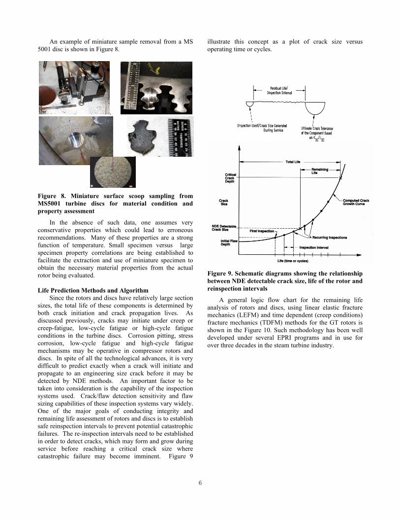
One of the major goals of conducting integrity and
remaining life assessment of rotors and discs is to establish
safe reinspection intervals to prevent potential catastrophic
failures. The re-inspection intervals need to be established
in order to detect cracks, which may form and grow during
service before reaching a critical crack size where
catastrophic failure may become imminent. Figure 9
illustrate this concept as a plot of crack size versus
operating time or cycles.
Figure 9. Schematic diagrams showing the relationship
between NDE detectable crack size, life of the rotor and
reinspection intervals
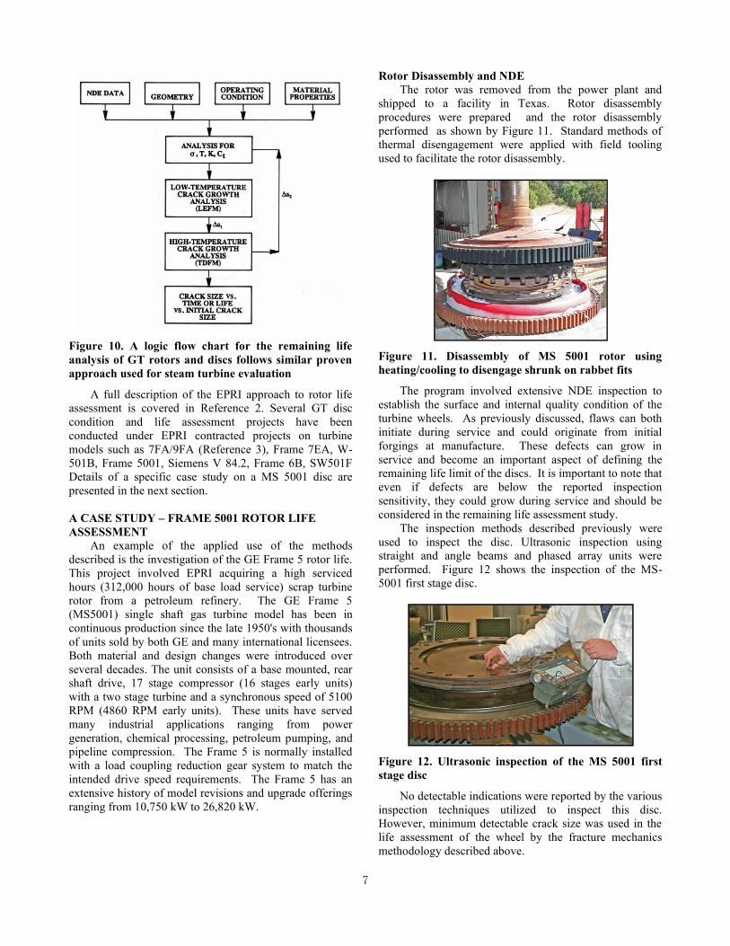
A general logic flow chart for the remaining life
analysis of rotors and discs, using linear elastic fracture
mechanics (LEFM) and time dependent (creep conditions)
fracture mechanics (TDFM) methods for the GT rotors is
shown in the Figure 10. Such methodology has been well
developed under several EPRI programs and in use for
over three decades in the steam turbine industry.
7
Figure 10. A logic flow chart for the remaining life
analysis of GT rotors and discs follows similar proven
approach used for steam turbine evaluation
A full description of the EPRI approach to rotor life
assessment is covered in Reference 2. Several GT disc
condition and life assessment projects have been
conducted under EPRI contracted projects on turbine
models such as 7FA/9FA (Reference 3), Frame 7EA, W-
501B, Frame 5001, Siemens V 84.2, Frame 6B, SW501F
Details of a specific case study on a MS 5001 disc are
presented in the next section.
A CASE STUDY – FRAME 5001 ROTOR LIFE
ASSESSMENT
An example of the applied use of the methods
described is the investigation of the GE Frame 5 rotor life.
This project involved EPRI acquiring a high serviced
hours (312,000 hours of base load service) scrap turbine
rotor from a petroleum refinery. The GE Frame 5
(MS5001) single shaft gas turbine model has been in
continuous production since the late 1950's with thousands
of units sold by both GE and many international licensees.
Both material and design changes were introduced over
several decades. The unit consists of a base mounted, rear
shaft drive, 17 stage compressor (16 stages early units)
with a two stage turbine and a synchronous speed of 5100
RPM (4860 RPM early units). These units have served
many industrial applications ranging from power
generation, chemical processing, petroleum pumping, and
pipeline compression. The Frame 5 is normally installed
with a load coupling reduction gear system to match the
intended drive speed requirements. The Frame 5 has an
extensive history of model revisions and upgrade offerings
ranging from 10,750 kW to 26,820 kW.
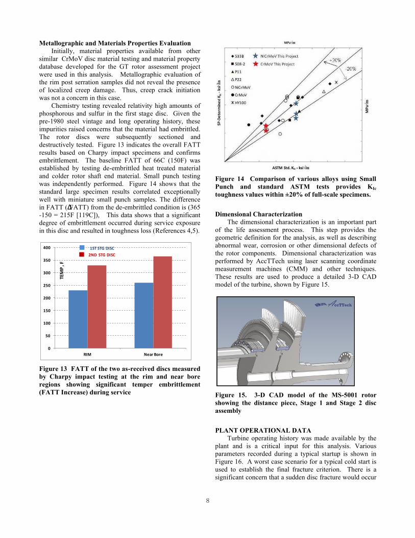
Rotor Disassembly and NDE
The rotor was removed from the power plant and
shipped to a facility in Texas. Rotor disassembly
procedures were prepared and the rotor disassembly
performed as shown by Figure 11. Standard methods of
thermal disengagement were applied with field tooling
used to facilitate the rotor disassembly.
Figure 11. Disassembly of MS 5001 rotor using
heating/cooling to disengage shrunk on rabbet fits
The program involved extensive NDE inspection to
establish the surface and internal quality condition of the
turbine wheels. As previously discussed, flaws can both
initiate during service and could originate from initial
forgings at manufacture. These defects can grow in
service and become an important aspect of defining the
remaining life limit of the discs. It is important to note that
even if defects are below the reported inspection
sensitivity, they could grow during service and should be
considered in the remaining life assessment study.
The inspection methods described previously were
used to inspect the disc. Ultrasonic inspection using
straight and angle beams and phased array units were
performed. Figure 12 shows the inspection of the MS-
5001 first stage disc.
Figure 12. Ultrasonic inspection of the MS 5001 first
stage disc
No detectable indications were reported by the various
inspection techniques utilized to inspect this disc.
However, minimum detectable crack size was used in the
life assessment of the wheel by the fracture mechanics
methodology described above.
8
Metallographic and Materials Properties Evaluation
Initially, material properties available from other
similar CrMoV disc material testing and material property
database developed for the GT rotor assessment project
were used in this analysis. Metallographic evaluation of
the rim post serration samples did not reveal the presence
of localized creep damage. Thus, creep crack initiation
was not a concern in this case.
Chemistry testing revealed relativity high amounts of
phosphorous and sulfur in the first stage disc. Given the
pre-1980 steel vintage and long operating history, these
impurities raised concerns that the material had embrittled.
The rotor discs were subsequently sectioned and
destructively tested. Figure 13 indicates the overall FATT
results based on Charpy impact specimens and confirms
embrittlement. The baseline FATT of 66C (150F) was
established by testing de-embrittled heat treated material
and colder rotor shaft end material. Small punch testing
was independently performed. Figure 14 shows that the
standard large specimen results correlated exceptionally
well with miniature small punch samples. The difference
in FATT (ΔFATT) from the de-embrittled condition is (365
-150 = 215F [119C]), This data shows that a significant
degree of embrittlement occurred during service exposure
in this disc and resulted in toughness loss (References 4,5).
Figure 13 FATT of the two as-received discs measured
by Charpy impact testing at the rim and near bore
regions showing significant temper embrittlement
(FATT Increase) during service
Figure 14 Comparison of various alloys using Small
Punch and standard ASTM tests provides KIc
toughness values within ±20% of full-scale specimens.
Dimensional Characterization
The dimensional characterization is an important part
of the life assessment process. This step provides the
geometric definition for the analysis, as well as describing
abnormal wear, corrosion or other dimensional defects of
the rotor components. Dimensional characterization was
performed by AccTTech using laser scanning coordinate
measurement machines (CMM) and other techniques.
These results are used to produce a detailed 3-D CAD
model of the turbine, shown by Figure 15.
Figure 15. 3-D CAD model of the MS-5001 rotor
showing the distance piece, Stage 1 and Stage 2 disc
assembly
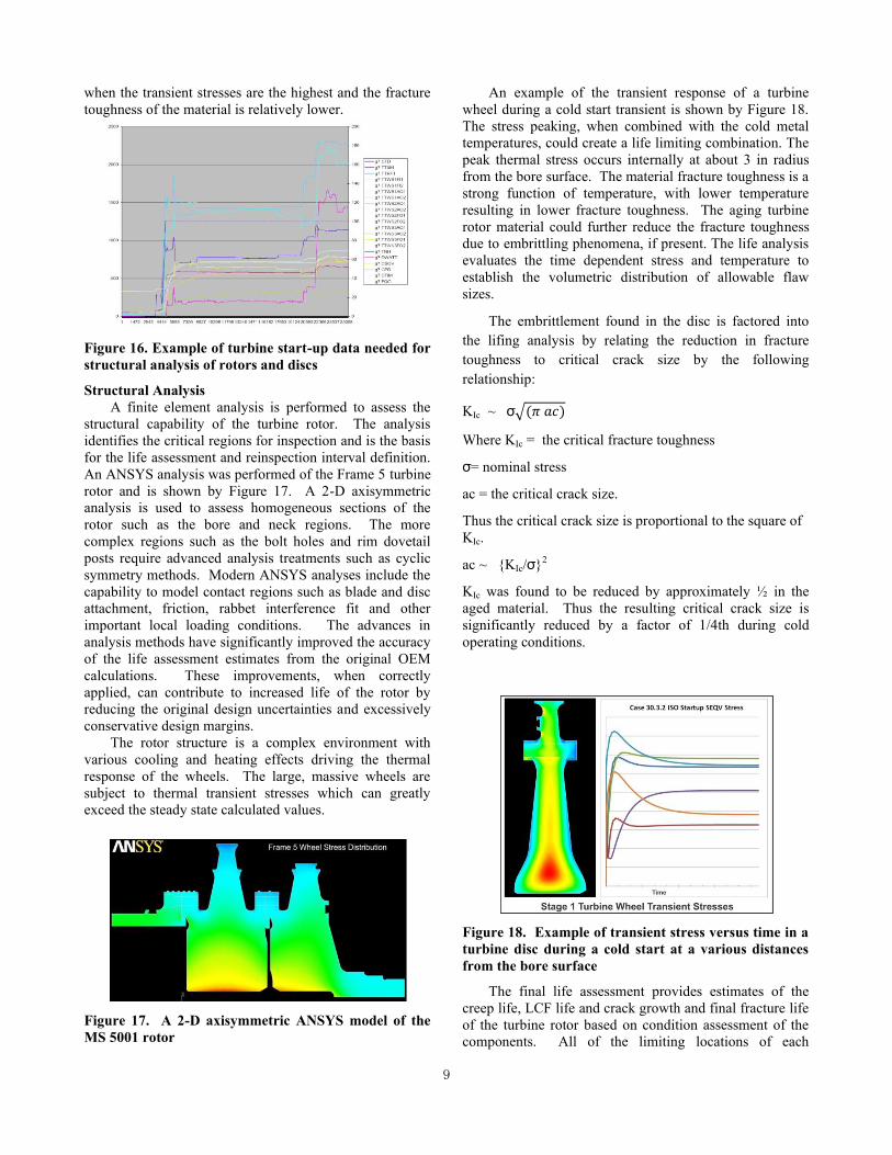
PLANT OPERATIONAL DATA
Turbine operating history was made available by the
plant and is a critical input for this analysis. Various
parameters recorded during a typical startup is shown in
Figure 16. A worst case scenario for a typical cold start is
used to establish the final fracture criterion. There is a
significant concern that a sudden disc fracture would occur
0
50
100
150
200
250
300
350
400
RIM Near Bore
TEM
P ,
F
1ST STG DISC
2ND STG DISC
9
when the transient stresses are the highest and the fracture
toughness of the material is relatively lower.
Figure 16. Example of turbine start-up data needed for
structural analysis of rotors and discs
Structural Analysis
A finite element analysis is performed to assess the
structural capability of the turbine rotor. The analysis
identifies the critical regions for inspection and is the basis
for the life assessment and reinspection interval definition.
An ANSYS analysis was performed of the Frame 5 turbine
rotor and is shown by Figure 17. A 2-D axisymmetric
analysis is used to assess homogeneous sections of the
rotor such as the bore and neck regions. The more
complex regions such as the bolt holes and rim dovetail
posts require advanced analysis treatments such as cyclic
symmetry methods. Modern ANSYS analyses include the
capability to model contact regions such as blade and disc
attachment, friction, rabbet interference fit and other
important local loading conditions. The advances in
analysis methods have significantly improved the accuracy
of the life assessment estimates from the original OEM
calculations. These improvements, when correctly
applied, can contribute to increased life of the rotor by
reducing the original design uncertainties and excessively
conservative design margins.
The rotor structure is a complex environment with
various cooling and heating effects driving the thermal
response of the wheels. The large, massive wheels are
subject to thermal transient stresses which can greatly
exceed the steady state calculated values.
Figure 17. A 2-D axisymmetric ANSYS model of the
MS 5001 rotor
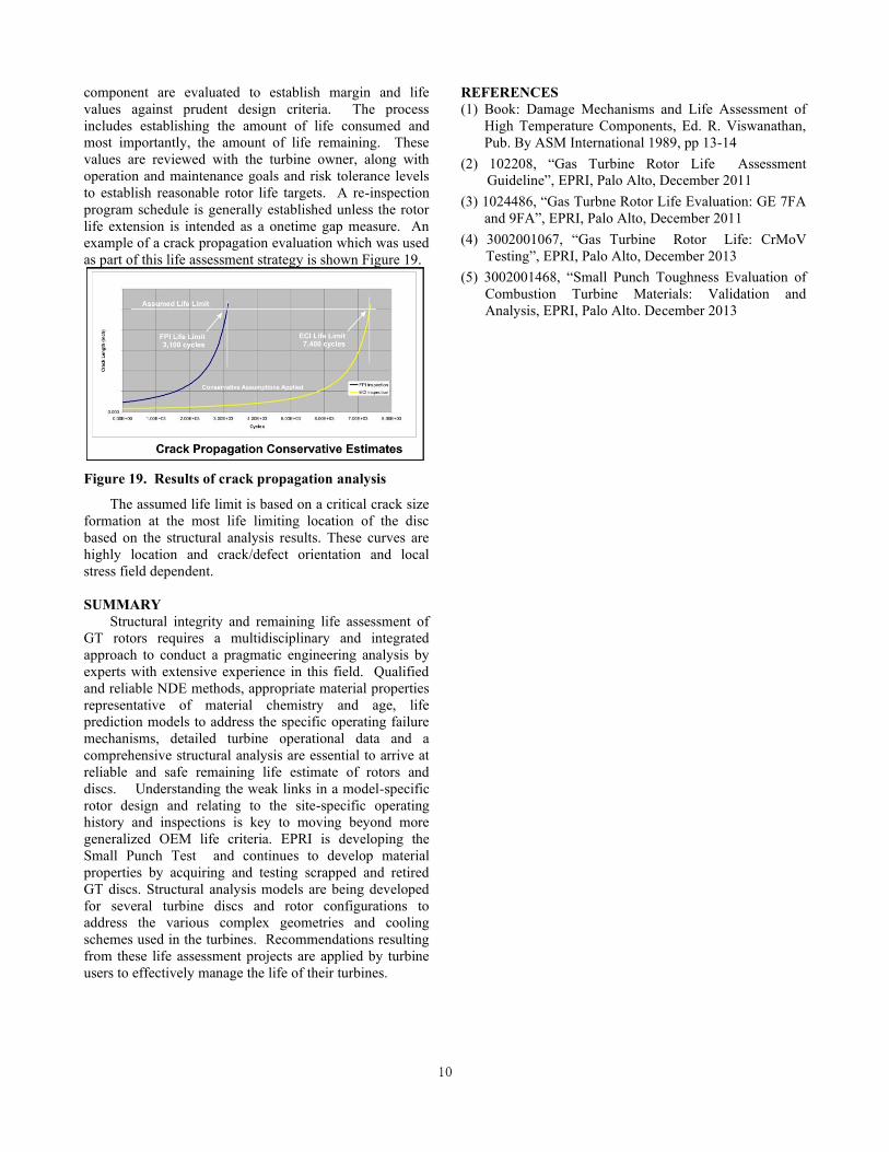
An example of the transient response of a turbine
wheel during a cold start transient is shown by Figure 18.
The stress peaking, when combined with the cold metal
temperatures, could create a life limiting combination. The
peak thermal stress occurs internally at about 3 in radius
from the bore surface. The material fracture toughness is a
strong function of temperature, with lower temperature
resulting in lower fracture toughness. The aging turbine
rotor material could further reduce the fracture toughness
due to embrittling phenomena, if present. The life analysis
evaluates the time dependent stress and temperature to
establish the volumetric distribution of allowable flaw
sizes.
The embrittlement found in the disc is factored into
the lifing analysis by relating the reduction in fracture
toughness to critical crack size by the following
relationship:
KIc ~ σ √(𝜋 𝑎𝑐)
Where KIc = the critical fracture toughness
σ = nominal stress
ac = the critical crack size.
Thus the critical crack size is proportional to the square of
KIc.
ac ~ {KIc/σ }2
KIc was found to be reduced by approximately ½ in the
aged material. Thus the resulting critical crack size is
significantly reduced by a factor of 1/4th during cold
operating conditions.
Figure 18. Example of transient stress versus time in a
turbine disc during a cold start at a various distances
from the bore surface
The final life assessment provides estimates of the
creep life, LCF life and crack growth and final fracture life
of the turbine rotor based on condition assessment of the
components. All of the limiting locations of each
10
component are evaluated to establish margin and life
values against prudent design criteria. The process
includes establishing the amount of life consumed and
most importantly, the amount of life remaining. These
values are reviewed with the turbine owner, along with
operation and maintenance goals and risk tolerance levels
to establish reasonable rotor life targets. A re-inspection
program schedule is generally established unless the rotor
life extension is intended as a onetime gap measure. An
example of a crack propagation evaluation which was used
as part of this life assessment strategy is shown Figure 19.
Figure 19. Results of crack propagation analysis
The assumed life limit is based on a critical crack size
formation at the most life limiting location of the disc
based on the structural analysis results. These curves are
highly location and crack/defect orientation and local
stress field dependent.
SUMMARY
Structural integrity and remaining life assessment of
GT rotors requires a multidisciplinary and integrated
approach to conduct a pragmatic engineering analysis by
experts with extensive experience in this field. Qualified
and reliable NDE methods, appropriate material properties
representative of material chemistry and age, life
prediction models to address the specific operating failure
mechanisms, detailed turbine operational data and a
comprehensive structural analysis are essential to arrive at
reliable and safe remaining life estimate of rotors and
discs. Understanding the weak links in a model-specific
rotor design and relating to the site-specific operating
history and inspections is key to moving beyond more
generalized OEM life criteria. EPRI is developing the
Small Punch Test and continues to develop material
properties by acquiring and testing scrapped and retired
GT discs. Structural analysis models are being developed
for several turbine discs and rotor configurations to
address the various complex geometries and cooling
schemes used in the turbines. Recommendations resulting
from these life assessment projects are applied by turbine
users to effectively manage the life of their turbines.
REFERENCES
(1) Book: Damage Mechanisms and Life Assessment of
High Temperature Components, Ed. R. Viswanathan,
Pub. By ASM International 1989, pp 13-14
(2) 102208, “Gas Turbine Rotor Life Assessment
Guideline”, EPRI, Palo Alto, December 2011
(3) 1024486, “Gas Turbne Rotor Life Evaluation: GE 7FA
and 9FA”, EPRI, Palo Alto, December 2011
(4) 3002001067, “Gas Turbine Rotor Life: CrMoV
Testing”, EPRI, Palo Alto, December 2013
(5) 3002001468, “Small Punch Toughness Evaluation of
Combustion Turbine Materials: Validation and
Analysis, EPRI, Palo Alto. December 2013