Embed Size (px)
Citation preview
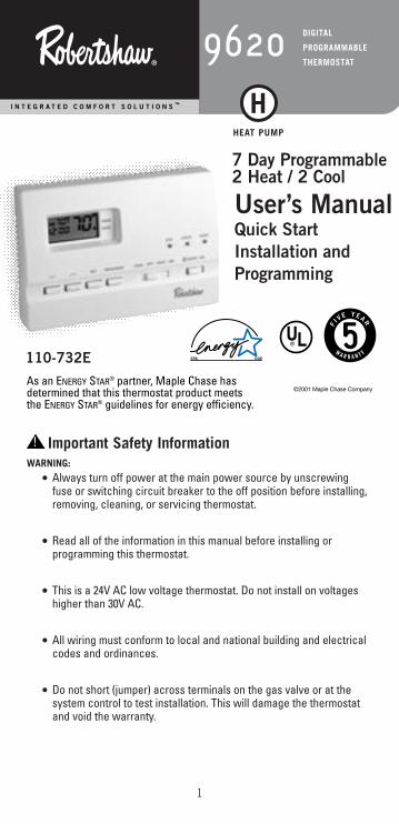
Important Safety InformationWARNING:
• Always turn off power at the main power source by unscrewingfuse or switching circuit breaker to the off position before installing,removing, cleaning, or servicing thermostat.
• Read all of the information in this manual before installing or programming this thermostat.
• This is a 24V AC low voltage thermostat. Do not install on voltageshigher than 30V AC.
• All wiring must conform to local and national building and electricalcodes and ordinances.
• Do not short (jumper) across terminals on the gas valve or at thesystem control to test installation. This will damage the thermostatand void the warranty.
1
110-732E
7 Day Programmable2 Heat / 2 Cool
W A R R A N T Y
I N T E G R A T E D C O M F O R T S O L U T I O N S ™
DIGITAL
PROGRAMMABLE
THERMOSTAT9620
User’s Manual Quick Start Installation and Programming
®
HEAT PUMP
H
©2001 Maple Chase CompanyAs an ENERGY STAR® partner, Maple Chase has determined that this thermostat product meets the ENERGY STAR® guidelines for energy efficiency.
!
Features• Four preprogrammed ENERGY STAR® setpoints for each day of the week• Quickset™ programming for quickly programming all days of the
week simultaneously• Energy Efficient Recovery (EER™)• Residual cooling for added air conditioning efficiency• Two AA ENERGIZER® brand batteries retain program memory,
even during power outages• Low battery indicator• Multi-colored LED indicators for system status• Zone compatible as master thermostat• Fahrenheit/Celsius display option• Programmable from 45°F (7°C) to 90°F (32°C)• Accuracy within ±1 degree• Adjustable temperature differential: 1-3 degrees• Maintains summer and winter programming
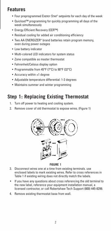
Step 1: Replacing Existing Thermostat1. Turn off power to heating and cooling system.2. Remove cover of old thermostat to expose wires. (Figure 1)
FIGURE 13. Disconnect wires one at a time from existing terminals. use
enclosed labels to mark existing wires. Refer to cross references inTable 1 if existing wiring does not directly match the labels.
• If you have any questions about cross referencing the old terminal tothe new label, reference your equipment installation manual, alicensed contractor, or call Robertshaw Tech Support (800) 445-8299.
4. Remove existing thermostat base from wall.
2
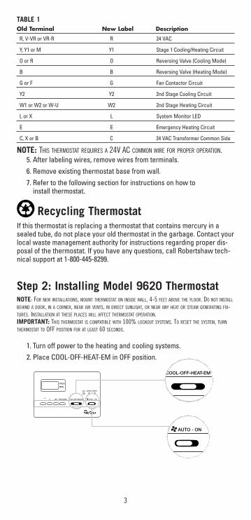
TABLE 1Old Terminal New Label Description
R, V-VR or VR-R R 24 VAC
Y, Y1 or M Y1 Stage 1 Cooling/Heating Circuit
O or R O Reversing Valve (Cooling Mode)
B B Reversing Valve (Heating Mode)
G or F G Fan Contactor Circuit
Y2 Y2 2nd Stage Cooling Circuit
W1 or W2 or W-U W2 2nd Stage Heating Circuit
L or X L System Monitor LED
E E Emergency Heating Circuit
C, X or B C 24 VAC Transformer Common Side
NOTE: THIS THERMOSTAT REQUIRES A 24V AC COMMON WIRE FOR PROPER OPERATION.5. After labeling wires, remove wires from terminals.6. Remove existing thermostat base from wall.7. Refer to the following section for instructions on how to
install thermostat.
Recycling ThermostatIf this thermostat is replacing a thermostat that contains mercury in asealed tube, do not place your old thermostat in the garbage. Contact yourlocal waste management authority for instructions regarding proper dis-posal of the thermostat. If you have any questions, call Robertshaw tech-nical support at 1-800-445-8299.
Step 2: Installing Model 9620 ThermostatNOTE: FOR NEW INSTALLATIONS, MOUNT THERMOSTAT ON INSIDE WALL, 4-5 FEET ABOVE THE FLOOR. DO NOT INSTALL
BEHIND A DOOR, IN A CORNER, NEAR AIR VENTS, IN DIRECT SUNLIGHT, OR NEAR ANY HEAT OR STEAM GENERATING FIX-TURES. INSTALLATION AT THESE PLACES WILL AFFECT THERMOSTAT OPERATION.IMPORTANT: THIS THERMOSTAT IS COMPATIBLE WITH 100% LOCKOUT SYSTEMS. TO RESET THE SYSTEM, TURN
THERMOSTAT TO OFF POSITION FOR AT LEAST 60 SECONDS.
1. Turn off power to the heating and cooling systems.2. Place COOL-OFF-HEAT-EM in OFF position.
3
PROG
MAN
SET PROG/MAN COOL-OFF-HEAT-EM
AUX CHECK EMER
AUTO - ON>>
AUTO - ON
COOL-OFF-HEAT-EM
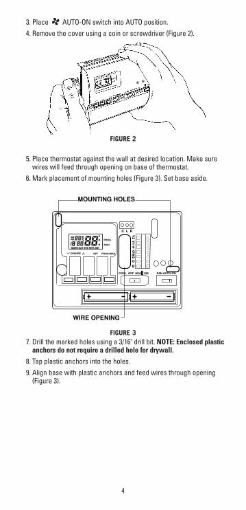
3. Place AUTO-ON switch into AUTO position.4. Remove the cover using a coin or screwdriver (Figure 2).
FIGURE 2
5. Place thermostat against the wall at desired location. Make surewires will feed through opening on base of thermostat.
6. Mark placement of mounting holes (Figure 3). Set base aside.
FIGURE 37. Drill the marked holes using a 3/16" drill bit. NOTE: Enclosed plastic
anchors do not require a drilled hole for drywall.
8. Tap plastic anchors into the holes.9. Align base with plastic anchors and feed wires through opening
(Figure 3).
4
EM
PROG
MAN
Y2
Y1
EGW
2
�
�
FAN AUTO ONCOOL OFF HEAT EM
CHANGE SET PROG/MAN
AMPM
MORN DAY EVE NITE EER
�
�
OB
C L R
MOUNTING HOLES
WIRE OPENING
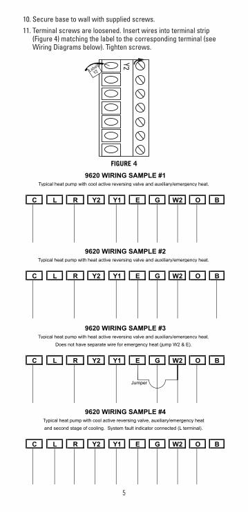
10. Secure base to wall with supplied screws.11. Terminal screws are loosened. Insert wires into terminal strip
(Figure 4) matching the label to the corresponding terminal (seeWiring Diagrams below). Tighten screws.
5
9620 WIRING SAMPLE #1
Y1 E G W2C L R Y2
Typical heat pump with cool active reversing valve and auxiliary/emergency heat.
O B
B
9620 WIRING SAMPLE #2
C L R Y2 Y1 E G W2 O
Typical heat pump with heat active reversing valve and auxiliary/emergency heat.
R Y2
Jumper
9620 WIRING SAMPLE #3
BY1 E G W2C L O
Typical heat pump with heat active reversing valve and auxiliary/emergency heat.
Does not have separate wire for emergency heat (jump W2 & E).
O B
9620 WIRING SAMPLE #4
C W2L R Y2 Y1 E G
Typical heat pump with cool active reversing valve, auxiliary/emergency heat
and second stage of cooling. System fault indicator connected (L terminal).
FIGURE 4
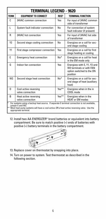
6
12. Install two AA ENERGIZER® brand batteries or equivalent into batterycompartment. Be sure to match positive (+) ends of batteries withpositive (+) battery terminals in the battery compartment.
13. Replace cover on thermostat by snapping into place.14. Turn on power to system. Test thermostat as described in the
following section.
TERMINAL LEGEND - 9620TERM EQUIPMENT TO CONNECT REQ? TERMINAL FUNCTION
C 24VAC common connection Yes For input of 24VAC commonside of transformer
L System fault indicator connection No For connection of systemfault indicator (if present)
R 24VAC hot connection Yes For input of 24VAC hot sideof transformer
Y2 Second stage cooling connection No Energizes on a call for sec-ond stage cooling
Y1 First stage compressor connection Yes Energizes on a call for firststage heating or cooling
E Emergency heat connection No* Energizes on a call for heatin the EM mode only
G Indoor fan connection Yes Energizes with E, Y1, Y2 andW2 terminals or with FANoption switched to the ONposition
W2 Second stage heat connection No* Energizes on a call for sec-ond stage of heat (auxiliaryheat)
O Cool active reversing Yes** Energizes when in the invalve connection COOL mode
B Heat active reversing Yes** Energizes when in the valve connection HEAT or EM modes
* For systems using a backup heat source. If separate E terminal connection is not available,jumper E and W2.
** Most heat pump systems will have a cool active OR a heat active reversing valve. Use the appropriate terminal.

Step 3: Testing the ThermostatWARNING: DO NOT SHORT (JUMPER) ACROSS TERMINALS OF GAS VALVE OR SYSTEM CONTROLTO TEST OPERATION. THIS WILL DAMAGE THE THERMOSTAT AND VOID YOUR WARRANTY.
CAUTION: DO NOT SWITCH SYSTEM TO COOL IF THE TEMPERATURE IS BELOW 50°F (10°C). THIS CAN DAMAGE
THE AIR CONDITIONING SYSTEM AND CAUSE PERSONAL INJURY.
1. Place the COOL-OFF-HEAT-EM switch into the COOL position
2. Press the button until the temperature setting is at least 3 degrees below the room temperature. The airconditioning system should turn on within a few seconds.
NOTE: ONCE THE THERMOSTAT TURNS THE SYSTEM OFF WHILE IN THE COOL OR HEAT MODE, A BUILT-IN DELAY KEEPS THE COM-PRESSOR FROM TURNING ON FOR ABOUT 5 MINUTES. THIS PROTECTS THE COMPRESSOR. NO ADDITIONAL TIME DELAY RELAY (DELAY ONBREAK) IS NECESSARY. TO OVERRIDE THE 5-MINUTE DELAY FOR INSTALLATION, PRESS RESET. THIS WILL ERASE THE DELAY AS WELLAS ALL PROGRAMMING.
3. Put the COOL-OFF-HEAT-EM switch into the OFF position. The air conditioning system should turn off. The fan may continue to run for a short period of time.
4. Put the COOL-OFF-HEAT-EM switch into the HEAT position.
5. Press the button until the temperature setting is at least 3 degrees above room temperature. The heating system should turnon. The fan may not turn on immediately, depending on the fan delaybuilt into the furnace.
6. Put the COOL-OFF-HEAT-EM switch into the OFF position. The heating system should turn off. Once again, the fan may have a delay.
7. Put the AUTO-ON switch to the ON position. The blower fan should turn on.
8. Put the AUTO-ON switch to the AUTO position. The blower fan should turn off.
7
COOL-OFF-HEAT-EM
COOL-OFF-HEAT-EM
COOL-OFF-HEAT-EM
COOL-OFF-HEAT-EM
AUTO - ON
AUTO - ON
>
>
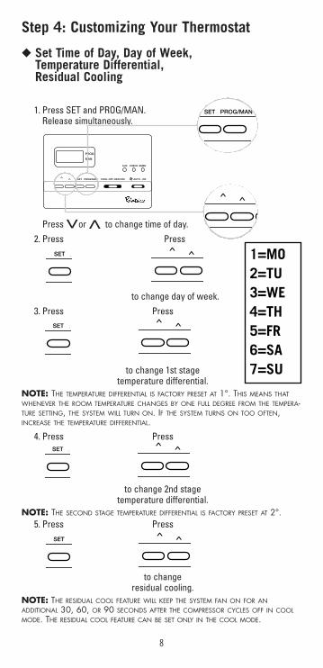
Step 4: Customizing Your Thermostat
◆ Set Time of Day, Day of Week,Temperature Differential,Residual Cooling
1. Press SET and PROG/MAN.Release simultaneously.
Press or to change time of day.2. Press Press
to change day of week.3. Press Press
to change 1st stagetemperature differential.
NOTE: THE TEMPERATURE DIFFERENTIAL IS FACTORY PRESET AT 1°. THIS MEANS THATWHENEVER THE ROOM TEMPERATURE CHANGES BY ONE FULL DEGREE FROM THE TEMPERA-TURE SETTING, THE SYSTEM WILL TURN ON. IF THE SYSTEM TURNS ON TOO OFTEN,INCREASE THE TEMPERATURE DIFFERENTIAL.
4. Press Press
to change 2nd stagetemperature differential.
NOTE: THE SECOND STAGE TEMPERATURE DIFFERENTIAL IS FACTORY PRESET AT 2°.5. Press Press
to changeresidual cooling.
NOTE: THE RESIDUAL COOL FEATURE WILL KEEP THE SYSTEM FAN ON FOR ANADDITIONAL 30, 60, OR 90 SECONDS AFTER THE COMPRESSOR CYCLES OFF IN COOLMODE. THE RESIDUAL COOL FEATURE CAN BE SET ONLY IN THE COOL MODE.
8
>>
PROG
MAN
SET PROG/MAN COOL-OFF-HEAT-EM
AUX CHECK EMER
AUTO - ON>>
SET PROG/MAN
SET P >> 1=MO2=TU3=WE4=TH5=FR6=SA7=SU
SET P >>
SET P >>
SET P >>
>>

◆ Changing Fahrenheit (F) to Celsius (C)Press and hold SET. Press
Release both simultaneously.
◆ Energy Efficient Recovery (EER™)The Energy Efficient Recovery (EER™) feature looks ahead up to 2 hoursprior to the end of the setback (or set-up) period to begin monitoring per-formance and calculating when to turn on your system. It also determineswhether the auxiliary heat or cool stages should be activated prior to set-point time to meet your chosen setpoint temperature. The thermostat willindicate EER in the display when this program feature is active. The EER™feature will lockout the auxiliary stages until 20 minutes prior to upcomingsetpoint time to utilize the most energy efficient first stage. The auxiliarystages of heating and cooling will be available during this lock-out periodto maintain the setpoint temperature should the system not be able tokeep up with the heating or cooling demand.
Step 5: Setting the ProgramThis Robertshaw thermostat is preprogrammed with the following ENERGY STAR® settings for the greatest energy savings.Setting Time Heat Setpoint Cool Setpoint
Temperature Temperature
MORN 6:00 a.m. 70°F 78°FDAY 8:00 a.m. 62°F 85°FEVE 5:00 p.m. 70°F 78°FNITE 10:00 p.m. 62°F 82°FThese settings can be customized using the following QuickSet™ or dailyprogramming guides.
9
SET P>
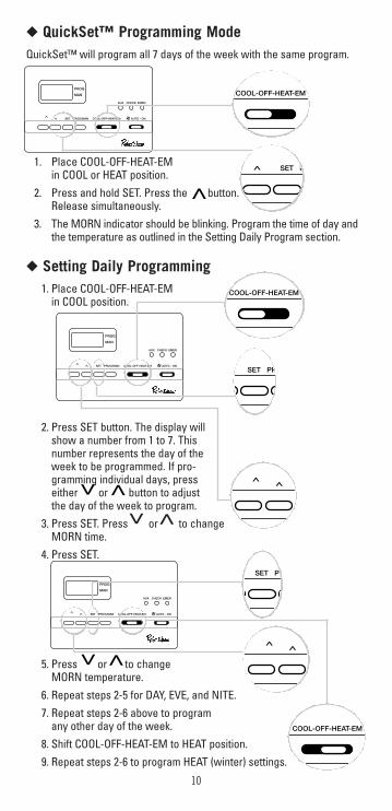
◆ QuickSet™ Programming ModeQuickSet™ will program all 7 days of the week with the same program.
1. Place COOL-OFF-HEAT-EMin COOL or HEAT position.
2. Press and hold SET. Press the button.Release simultaneously.
3. The MORN indicator should be blinking. Program the time of day andthe temperature as outlined in the Setting Daily Program section.
◆ Setting Daily Programming1. Place COOL-OFF-HEAT-EM
in COOL position.
2. Press SET button. The display willshow a number from 1 to 7. Thisnumber represents the day of theweek to be programmed. If pro-gramming individual days, presseither or button to adjustthe day of the week to program.
3. Press SET. Press or to change MORN time.
4. Press SET.
5. Press or to change MORN temperature.
6. Repeat steps 2-5 for DAY, EVE, and NITE.7. Repeat steps 2-6 above to program
any other day of the week.8. Shift COOL-OFF-HEAT-EM to HEAT position.9. Repeat steps 2-6 to program HEAT (winter) settings.
10
>>
PROG
MAN
SET PROG/MAN COOL-OFF-HEAT-EM
AUX CHECK EMER
AUTO - ON>>
COOL-OFF-HEAT-EM
SET PR
>>
>>
PROG
MAN
SET PROG/MAN COOL-OFF-HEAT-EM
AUX CHECK EMER
AUTO - ON>>
SET PR
>>
PROG
MAN
SET PROG/MAN COOL-OFF-HEAT-EM
AUX CHECK EMER
AUTO - ON>>
SET P>
>
COOL-OFF-HEAT-EM
COOL-OFF-HEAT-EM
>>
11
>>ET PROG/MAN C
PROG
MAN
PROG
MAN
SET PROG/MAN COOL-OFF-HEAT-EM
AUX CHECK EMER
AUTO - ON>>
>>
PROG
MAN
SET PROG/MAN COOL-OFF-HEAT-EM
AUX CHECK EMER
AUTO - ON>>
PROG
MAN
SET PROG/MAN COOL-OFF-HEAT-EM
AUX CHECK EMER
AUTO - ON>>
AUTO - ON
SUMMER
WINTER
COOL-OFF-HEAT-EM
COOL-OFF-HEAT-EM
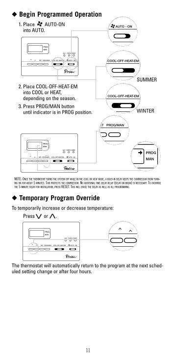
NOTE: ONCE THE THERMOSTAT TURNS THE SYSTEM OFF WHILE IN THE COOL OR HEAT MODE, A BUILT-IN DELAY KEEPS THE COMPRESSOR FROM TURN-ING ON FOR ABOUT 5 MINUTES. THIS PROTECTS THE COMPRESSOR. NO ADDITIONAL TIME DELAY RELAY (DELAY ON BREAK) IS NECESSARY. TO OVERRIDETHE 5-MINUTE DELAY FOR INSTALLATION, PRESS RESET. THIS WILL ERASE THE DELAY AS WELL AS ALL PROGRAMMING.
◆ Begin Programmed Operation1. Place AUTO-ON
into AUTO.
2. Place COOL-OFF-HEAT-EM into COOL or HEAT,depending on the season.
3. Press PROG/MAN buttonuntil indicator is in PROG position.
◆ Temporary Program OverrideTo temporarily increase or decrease temperature:
Press or .
The thermostat will automatically return to the program at the next sched-uled setting change or after four hours.
12
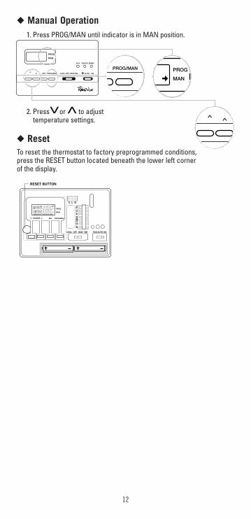
◆ Manual Operation1. Press PROG/MAN until indicator is in MAN position.
2. Press or to adjust temperature settings.
◆ ResetTo reset the thermostat to factory preprogrammed conditions, press the RESET button located beneath the lower left cornerof the display.
PROG
MAN
SET PROG/MAN COOL-OFF-HEAT-EM
AUX CHECK EMER
AUTO - ON>>T PROG/MAN PROG
MAN>>
PROG��MAN���
Y2���
Y1��
E��GW
2��
�
�
FAN AUTO ONCOOL OFF HEAT EM
CHANGE SET PROG/MAN
AMPM
MORN DAY EVE NITE EER
RESET BUTTON
OB
C L R
>>
13
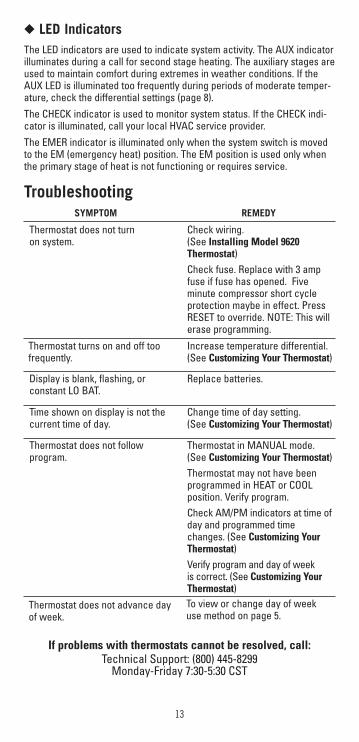
If problems with thermostats cannot be resolved, call: Technical Support: (800) 445-8299
Monday-Friday 7:30-5:30 CST
TroubleshootingSYMPTOM REMEDY
Thermostat does not turn on system.
Check wiring.(See Installing Model 9620Thermostat)Check fuse. Replace with 3 ampfuse if fuse has opened. Fiveminute compressor short cycleprotection maybe in effect. PressRESET to override. NOTE: This willerase programming.
Thermostat turns on and off toofrequently.
Increase temperature differential.(See Customizing Your Thermostat)
Display is blank, flashing, or constant LO BAT.
Replace batteries.
Time shown on display is not thecurrent time of day.
Change time of day setting. (See Customizing Your Thermostat)
Thermostat does not follow program.
Thermostat in MANUAL mode.(See Customizing Your Thermostat) Thermostat may not have beenprogrammed in HEAT or COOLposition. Verify program. Check AM/PM indicators at time ofday and programmed timechanges. (See Customizing YourThermostat)Verify program and day of week is correct. (See Customizing YourThermostat)
Thermostat does not advance day of week.
To view or change day of weekuse method on page 5.
◆ LED IndicatorsThe LED indicators are used to indicate system activity. The AUX indicatorilluminates during a call for second stage heating. The auxiliary stages areused to maintain comfort during extremes in weather conditions. If theAUX LED is illuminated too frequently during periods of moderate temper-ature, check the differential settings (page 8).The CHECK indicator is used to monitor system status. If the CHECK indi-cator is illuminated, call your local HVAC service provider.The EMER indicator is illuminated only when the system switch is movedto the EM (emergency heat) position. The EM position is used only whenthe primary stage of heat is not functioning or requires service.
14
Maple Chase Company2820 Thatcher RoadDowners Grove, Illinois 60515United States of America
Five-Year Limited WarrantyMaple Chase Company warrants to the original contractor installer, or tothe original consumer user, each new Robertshaw thermostat to be freefrom defects in materials and workmanship under normal use and servicefor a period of five (5) years from date of purchase. This warranty does notcover batteries, damage caused by batteries, damage resulting fromimproper installation, alteration, misuse or abuse of the thermostat occur-ring after the date of purchase.Maple Chase Company agrees to repair or replace at its option any thermo-stat under warranty provided it is returned within the warranty period,postage prepaid, with proof of the date of purchase. Cost of thermostatremoval or reinstallation is not the responsibility of Maple Chase Company.Repair or replacement as provided under this warranty is the exclusiveremedy of the consumer. Maple Chase Company shall not be liable for anyincidental or consequential damages for breach of any express or impliedwarranty on this product, or under any other theory of liability. Except to theextent prohibited by applicable law, any implied warranty of merchantabilityor fitness for a particular purpose on this product is limited to the durationof this warranty.Some states do not allow the exclusion or limitation of incidental or conse-quential damages, or allow limitations on how long an implied warrantylasts, so the above limitations or exclusions may not apply to you. This war-ranty gives you specific legal rights, and you may also have other rightswhich vary from state to state.
For warranty returns, send thermostat, shipping prepaid to:
Uni-Line North AmericaWarranty Claims Department
515 S. PromenadeCorona, CA 91719