Embed Size (px)
Citation preview
INTEGRATED COMPUTATIONAL MATERIALS ENGINEERING APPROACH TO DEVELOPMENT OF LIGHTWEIGHT
3GAHSS VEHICLE ASSEMBLY
Co-Principal Investigator: Dr. Louis G. Hector, Jr. Co-Principal Investigator: Ron Krupitzer
United States Automotive Materials Partnership June 17, 2014 Project ID
LM080 This presentation does not contain any proprietary, confidential, or otherwise restricted information
2
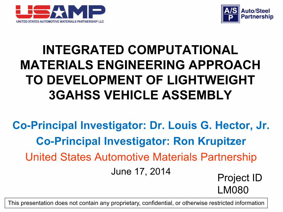
• Project Start Date: February 1, 2013 • Project End Date: January 31, 2017 • Percent Complete: 17%
A. Cost. Prohibitively high cost of finished materials is the greatest single barrier to the market viability of advanced lightweight materials for automotive vehicle applications
B. Performance. Low cost materials needed to achieve performance objectives may not exist today
C. Predictive modeling tools. Predictive tools that will guide low cost manufacturing of lightweight automotive structures would reduce the risk of developing new materials.
• Total project funding • DOE Share: $6,000,00 • Contractor Share: $2,571,253
• Funding received in FY13 : $348,72 • Funding for FY14: $1,603,04
– Contractor: $687,020
Timeline
Budget
Barriers
Participants
Overview
Universities/National Labs IndustryBrown University Chrysler Group LLC
Clemson University Ford Motor CompanyColorado School of Mines General Motors CompanyMichigan State University AK Steel Corporation
Pacific Northwest National Lab ArcelorMittalUniversity of Illinois Nucor Steel Corporation
Severstal NAConsortiums U. S. Steel
Auto/Steel Partnership EDAG, Inc.United States Automotive Materials Partnership Livermore Software Technology Corporation
3
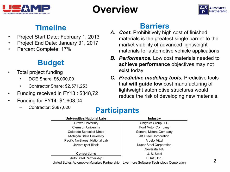
Project Goal: • To reduce the lead time in developing and applying lightweight third generation advanced
high strength steel (3GAHSS) by integrating material models of different length scales into an Integrated Computational Materials Engineering (ICME) model
Project Objectives • Identify, validate (within 15% experiments) and assemble length scale material models for
predicting 3GAHSS constitutive behavior for component forming and performance • Optimize assembly design using ICME-predicted 3GAHSS model to be 35% lighter and no
more than $3.18 cost per pound weight saved.
February 2013 – September 2013 Objectives • Launch project • Establish highly functional leveraged teams and communication channels essential to
coordinate the assembly and integration of the ICME model. • Begin task 2 (ICME model development) using QP980 steel as a baseline material • Identify baseline AHSS assembly for optimization using 3GAHSS • Identify steel processing pathways with a high probability of producing target DOE FOA
3GAHSS
Relevance
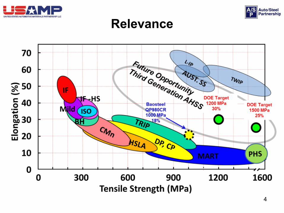
Relevance
4
5
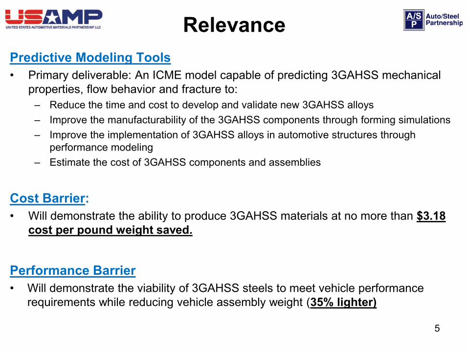
Predictive Modeling Tools • Primary deliverable: An ICME model capable of predicting 3GAHSS mechanical
properties, flow behavior and fracture to: – Reduce the time and cost to develop and validate new 3GAHSS alloys – Improve the manufacturability of the 3GAHSS components through forming simulations – Improve the implementation of 3GAHSS alloys in automotive structures through
performance modeling – Estimate the cost of 3GAHSS components and assemblies
Cost Barrier: • Will demonstrate the ability to produce 3GAHSS materials at no more than $3.18
cost per pound weight saved.
Performance Barrier • Will demonstrate the viability of 3GAHSS steels to meet vehicle performance
requirements while reducing vehicle assembly weight (35% lighter)
Relevance
6
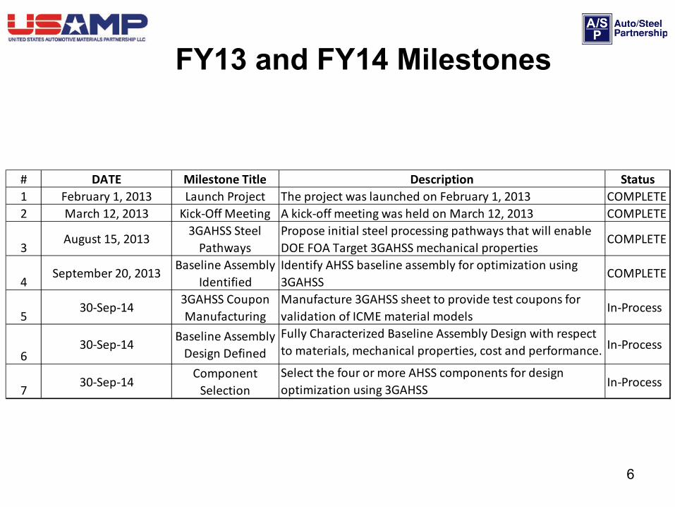
FY13 and FY14 Milestones
# DATE Milestone Title Description Status1 February 1, 2013 Launch Project The project was launched on February 1, 2013 COMPLETE2 March 12, 2013 Kick-Off Meeting A kick-off meeting was held on March 12, 2013 COMPLETE
3August 15, 2013 3GAHSS Steel
PathwaysPropose initial steel processing pathways that will enable DOE FOA Target 3GAHSS mechanical properties
COMPLETE
4September 20, 2013 Baseline Assembly
IdentifiedIdentify AHSS baseline assembly for optimization using 3GAHSS
COMPLETE
530-Sep-14 3GAHSS Coupon
ManufacturingManufacture 3GAHSS sheet to provide test coupons for validation of ICME material models
In-Process
630-Sep-14 Baseline Assembly
Design DefinedFully Characterized Baseline Assembly Design with respect to materials, mechanical properties, cost and performance. In-Process
7 30-Sep-14Component
SelectionSelect the four or more AHSS components for design optimization using 3GAHSS In-Process
• An ICME approach specifically aimed at 3GAHSS which will… – Further develop existing computational methodologies and tools – Enable the development of complete and consistent models both at the component and
assembly levels
• A highly collaborative partnership, under experienced USAMP consortium and A/SP leadership, has been created: automotive OEMs, steel companies, universities, a national lab and industry partners.
– OEM members responsible for: system requirements; acceptance criteria and performance targets in the integration and design of components for 3GAHSS automotive assemblies; coordinating university participation and contributions.
– A/SP Steel companies responsible for: design and manufacture of new 3GAHSS alloys and components to meet the project objectives.
– Universities and National Laboratory will develop and validate ICME models.
7
Approach/Strategy
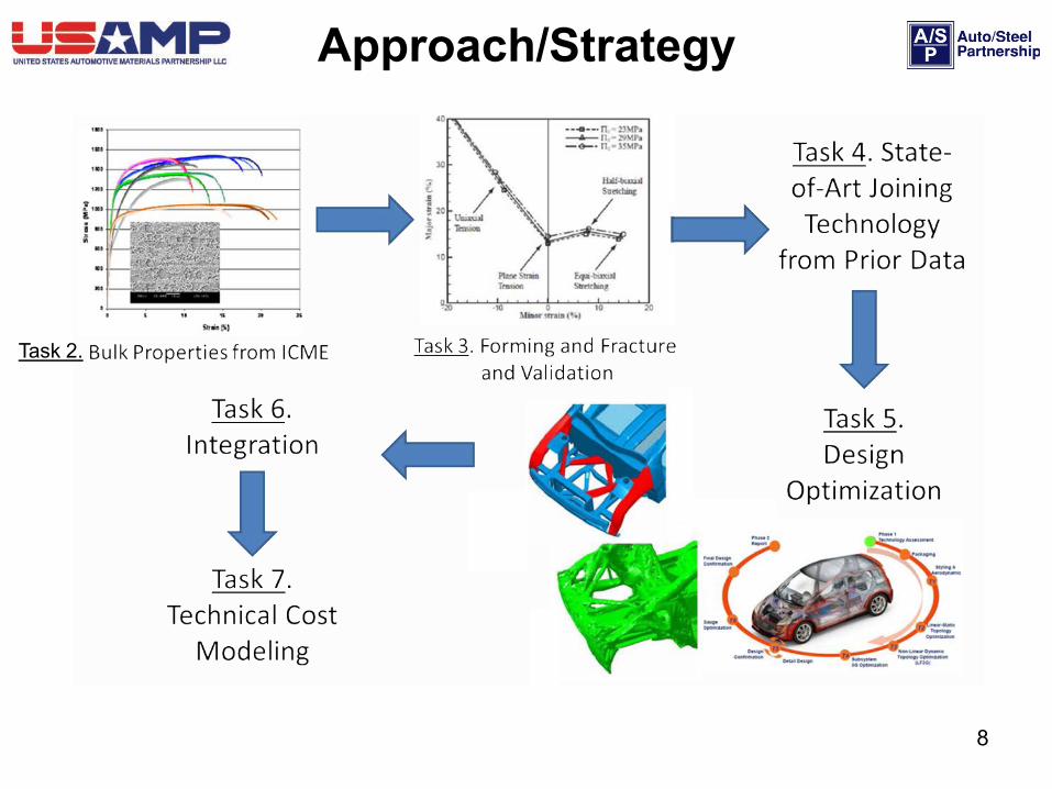
8
Approach/Strategy
Task 2.
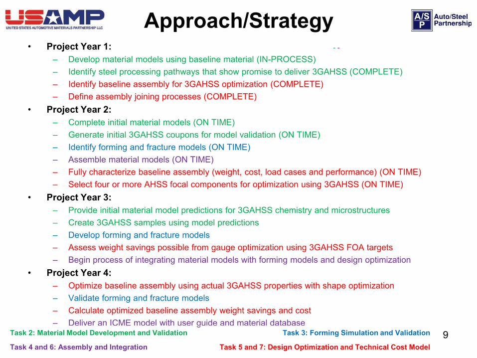
• Project Year 1: – Develop material models using baseline material (IN-PROCESS) – Identify steel processing pathways that show promise to deliver 3GAHSS (COMPLETE) – Identify baseline assembly for 3GAHSS optimization (COMPLETE) – Define assembly joining processes (COMPLETE)
• Project Year 2: – Complete initial material models (ON TIME) – Generate initial 3GAHSS coupons for model validation (ON TIME) – Identify forming and fracture models (ON TIME) – Assemble material models (ON TIME) – Fully characterize baseline assembly (weight, cost, load cases and performance) (ON TIME) – Select four or more AHSS focal components for optimization using 3GAHSS (ON TIME)
• Project Year 3: – Provide initial material model predictions for 3GAHSS chemistry and microstructures – Create 3GAHSS samples using model predictions – Develop forming and fracture models – Assess weight savings possible from gauge optimization using 3GAHSS FOA targets – Begin process of integrating material models with forming models and design optimization
• Project Year 4: – Optimize baseline assembly using actual 3GAHSS properties with shape optimization – Validate forming and fracture models – Calculate optimized baseline assembly weight savings and cost – Deliver an ICME model with user guide and material database
9
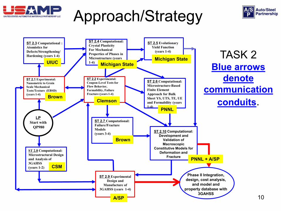
Approach/Strategy - -
Task 2: Material Model Development and Validation Task 3: Forming Simulation and Validation
Task 4 and 6: Assembly and Integration Task 5 and 7: Design Optimization and Technical Cost Model
10
Approach/Strategy
TASK 2 Blue arrows
denote communication
conduits. LP
Start with QP980
ST 2.1 Experimental: Nanometric to Grain Scale Mechanical Tests/Texture (EBSD) (years 1-4)
ST 2.2 Experimental: Coupon-Level Tests for Flow Behavior, Formability, Failure Fracture (years 1-4)
ST 2.8 Computational: Microstructural Design and Analysis of 3GAHSS (years 1-2)
ST 2.3 Computational : Atomistics for Defects/Strengthening/ Hardening (years 1-4)
ST 2.4 Computational: Crystal Plasticity For Mechanical Properties of Phases in Microstructure (years 1-4)
ST 2.9 Experimental Design and
Manufacture of 3GAHSS (years 1-4)
ST 2.5 Evolutionary Yield Function
(years 1-4)
ST 2.6 Computational: Microstructure-Based Finite Element Approach for Bulk Sheet YS, UTS, TE, UE and Formability (years 1-4)
ST 2.10 Computational: Development and
Validation of Macroscopic
Constitutive Models for Deformation and
Fracture
ST 2.7 Computational: Failure/Fracture Models (years 3-4)
Phase II Integration, design, cost analysis,
and model and property database with
3GAHSS
Brown
Brown
CSM
Michigan State UIUC Michigan State
Clemson
PNNL
PNNL + A/SP
A/SP
11
Project launched on February 1, 2013 and kicked off on March 12, 2013 • FY13 Milestones #1 and #2 • Established highly leveraged cross-functional task teams
– Monthly integration and coordination team meetings. – Monthly project leadership team meetings – Subtask participants engaged in teleconferences/visits
Task 3 Accomplishments: (Starts in Year 2)
Task 4 and Task 6 Accomplishments: • Outlined the model assembly and integration process (FY14 Milestone)
Task 5 and Task 7 Accomplishments: • Defined baseline assembly joining processes
– A/SP and EDAG selected spot welding with adhesive bonding for the baseline and optimized assemblies (FY14 Milestone)
• Identified the baseline assembly: side structure of a ’08MY four-door sedan (#4 FY13 Milestone)
– Characterized the baseline assembly in terms of weight, cost and performance – Developed a preliminary technical cost model (FY14 Milestone)
Technical Accomplishments and Progress
12
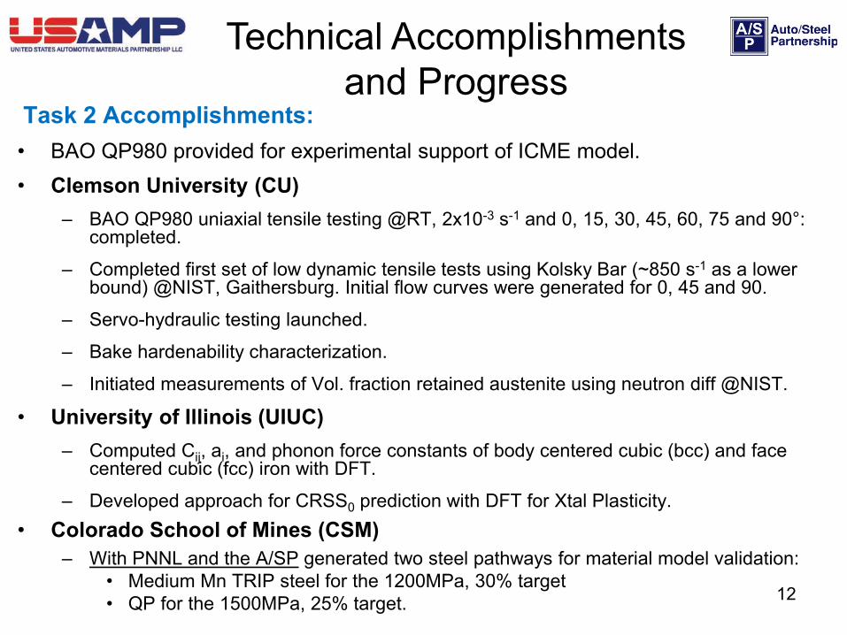
Task 2 Accomplishments: • BAO QP980 provided for experimental support of ICME model. • Clemson University (CU)
– BAO QP980 uniaxial tensile testing @RT, 2x10⁻³ s-1 and 0, 15, 30, 45, 60, 75 and 90°: completed.
– Completed first set of low dynamic tensile tests using Kolsky Bar (~850 s-1 as a lower bound) @NIST, Gaithersburg. Initial flow curves were generated for 0, 45 and 90.
– Servo-hydraulic testing launched.
– Bake hardenability characterization.
– Initiated measurements of Vol. fraction retained austenite using neutron diff @NIST.
• University of Illinois (UIUC) – Computed Cij, ai, and phonon force constants of body centered cubic (bcc) and face
centered cubic (fcc) iron with DFT.
– Developed approach for CRSS0 prediction with DFT for Xtal Plasticity. • Colorado School of Mines (CSM)
– With PNNL and the A/SP generated two steel pathways for material model validation: • Medium Mn TRIP steel for the 1200MPa, 30% target • QP for the 1500MPa, 25% target.
Technical Accomplishments and Progress
13
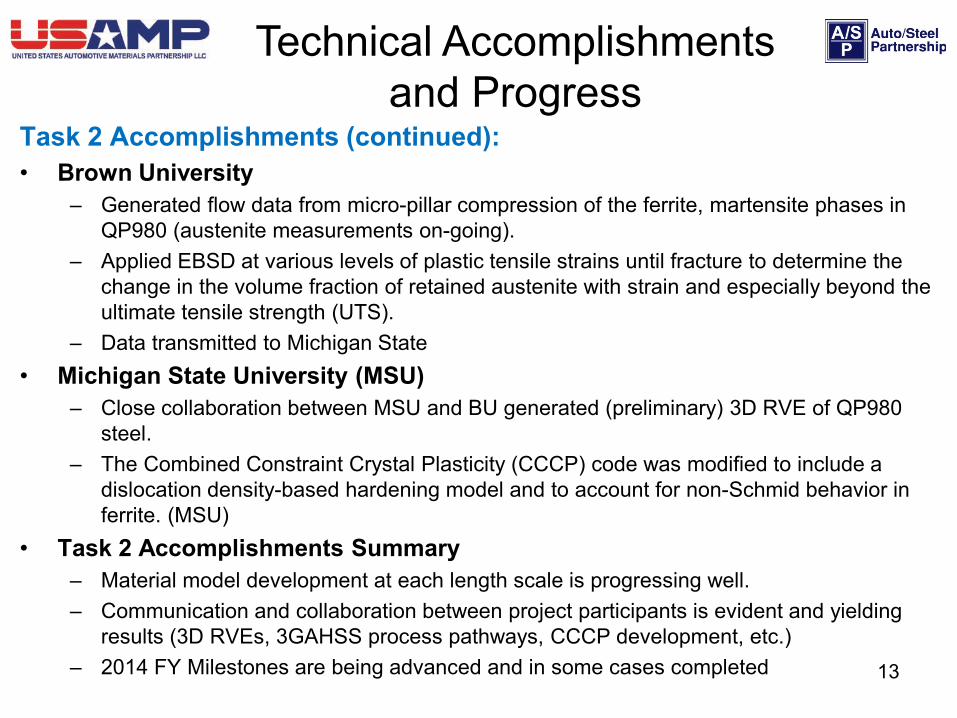
Task 2 Accomplishments (continued): • Brown University
– Generated flow data from micro-pillar compression of the ferrite, martensite phases in QP980 (austenite measurements on-going).
– Applied EBSD at various levels of plastic tensile strains until fracture to determine the change in the volume fraction of retained austenite with strain and especially beyond the ultimate tensile strength (UTS).
– Data transmitted to Michigan State • Michigan State University (MSU)
– Close collaboration between MSU and BU generated (preliminary) 3D RVE of QP980 steel.
– The Combined Constraint Crystal Plasticity (CCCP) code was modified to include a dislocation density-based hardening model and to account for non-Schmid behavior in ferrite. (MSU)
• Task 2 Accomplishments Summary – Material model development at each length scale is progressing well. – Communication and collaboration between project participants is evident and yielding
results (3D RVEs, 3GAHSS process pathways, CCCP development, etc.) – 2014 FY Milestones are being advanced and in some cases completed
Technical Accomplishments and Progress
14
Response to Reviewer’s Comments
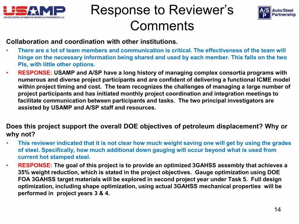
Collaboration and coordination with other institutions. • There are a lot of team members and communication is critical. The effectiveness of the team will
hinge on the necessary information being shared and used by each member. This falls on the two PIs, with little other options.
• RESPONSE: USAMP and A/SP have a long history of managing complex consortia programs with numerous and diverse project participants and are confident of delivering a functional ICME model within project timing and cost. The team recognizes the challenges of managing a large number of project participants and has initiated monthly project coordination and integration meetings to facilitate communication between participants and tasks. The two principal investigators are assisted by USAMP and A/SP staff and resources.
Does this project support the overall DOE objectives of petroleum displacement? Why or why not? • This reviewer indicated that it is not clear how much weight saving one will get by using the grades
of steel. Specifically, how much additional down gauging will occur beyond what is used from current hot stamped steel.
• RESPONSE: The goal of this project is to provide an optimized 3GAHSS assembly that achieves a 35% weight reduction, which is stated in the project objectives. Gauge optimization using DOE FOA 3GAHSS target materials will be explored in second project year under Task 5. Full design optimization, including shape optimization, using actual 3GAHSS mechanical properties will be performed in project years 3 & 4.
15
Response to Reviewer’s Comments
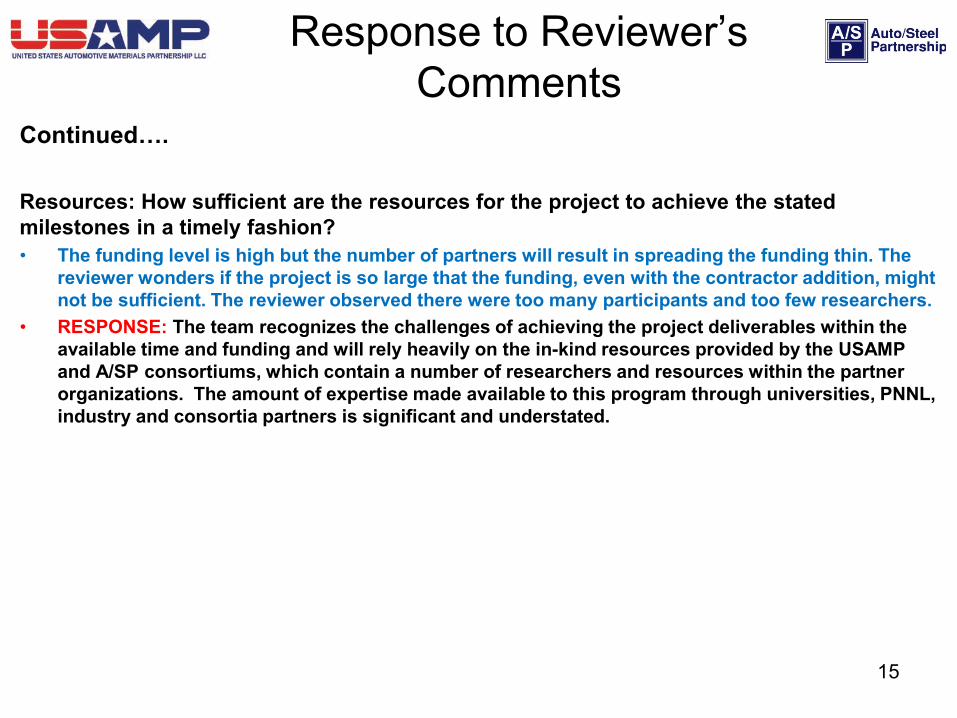
Continued…. Resources: How sufficient are the resources for the project to achieve the stated milestones in a timely fashion? • The funding level is high but the number of partners will result in spreading the funding thin. The
reviewer wonders if the project is so large that the funding, even with the contractor addition, might not be sufficient. The reviewer observed there were too many participants and too few researchers.
• RESPONSE: The team recognizes the challenges of achieving the project deliverables within the available time and funding and will rely heavily on the in-kind resources provided by the USAMP and A/SP consortiums, which contain a number of researchers and resources within the partner organizations. The amount of expertise made available to this program through universities, PNNL, industry and consortia partners is significant and understated.
16
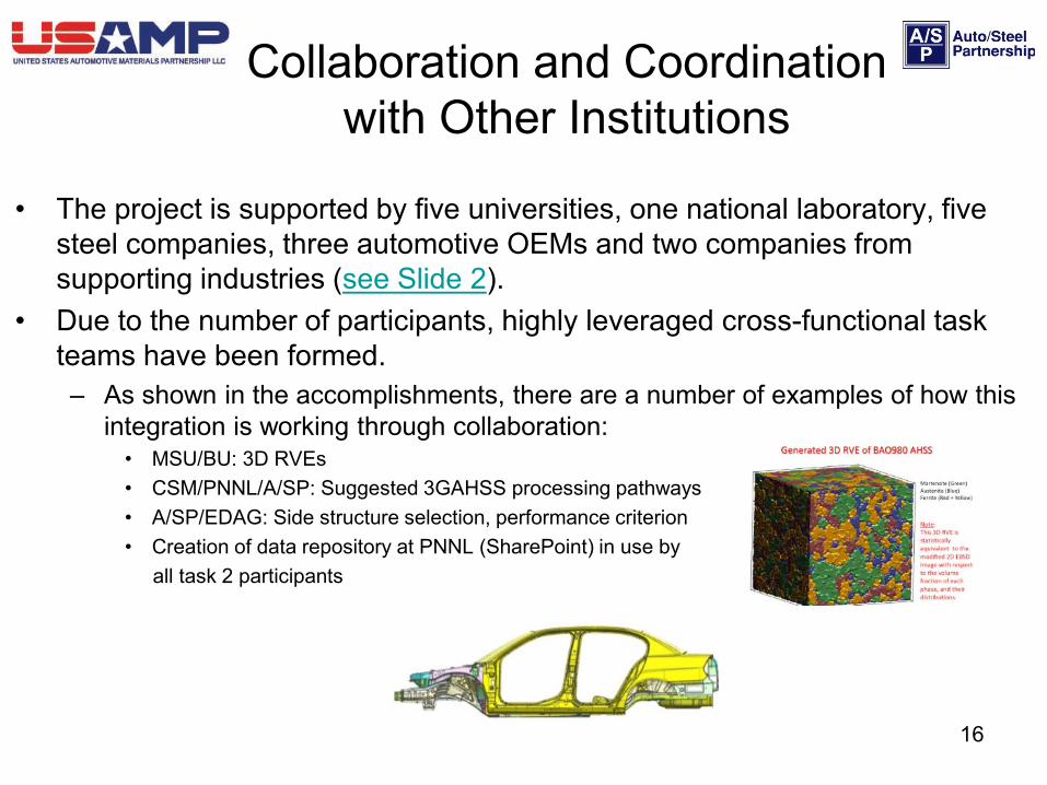
Collaboration and Coordination with Other Institutions
• The project is supported by five universities, one national laboratory, five steel companies, three automotive OEMs and two companies from supporting industries (see Slide 2).
• Due to the number of participants, highly leveraged cross-functional task teams have been formed. – As shown in the accomplishments, there are a number of examples of how this
integration is working through collaboration: • MSU/BU: 3D RVEs • CSM/PNNL/A/SP: Suggested 3GAHSS processing pathways • A/SP/EDAG: Side structure selection, performance criterion • Creation of data repository at PNNL (SharePoint) in use by all task 2 participants
17
For the period October 2013 – September 2014 • Task 2:
– Complete initial ICME material model development using baseline QP980 steel and define input constitutive material parameters needed for 3GAHSS
– Cast and process initial 3GAHSS heats into sheet using chemistry and processing recipes defined by Colorado School of Mines for the medium manganese TRIP and QP steels.
– Use experimental 3GAHSS coupons to validate and/or refine length-scale material models – Identify and validate fracture models
• Task 3: – Identify and validate forming models
• Task 4: – Assemble ICME material models with optimization loops using defined input/output parameters for
each material length scale model – Provide initial 3GAHSS chemistry and microstructure predictions using assembled material models
• Task 5: – Assess the performance of the baseline with respect to defined load cases. – Identify focal components for conversion to 3GAHSS – Evaluate the potential of the DOE FOA 3GAHSS to reduce component and assembly weight through
improved mechanical properties and gauge optimization • Task 6
– Develop ICME framework to integrate material models, forming models and design optimization
Proposed Future Work
18
• The ICME 3GAHSS project was launched on 01FEB13. – Highly leveraged cross-functional task teams have been established with monthly
integration and coordination team meetings.
• Material model development using QP980 steel as a baseline will continue into 2014FY.
– Model validation will begin with 3GAHSS coupons in 2014FY
• Model assembly will begin in 2014FY with the goal of providing 3GAHSS chemistry and microstructure predictions in early 2015FY.
• The project has established two steel processing pathways that have potential to meet the two DOE FOA 3GAHSS targets.
– 3GAHSS heats will be made and processed into sheet in 2014FY
• The baseline assembly has been identified and will be fully characterized in terms of weight, cost, and performance in 2014.
– Selection of AHSS focal components will be made in 2014FY and a case study will be initiated to assess the weight savings potential of 3GAHSS by virtue of improved properties and gauge optimization.
Summary
19
Back-Up Slides
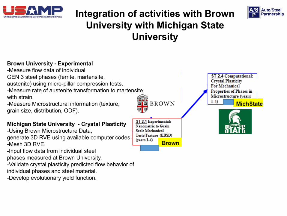
Integration of activities with Brown University with Michigan State
University
Brown University - Experimental -Measure flow data of individual GEN 3 steel phases (ferrite, martensite, austenite) using micro-pillar compression tests. -Measure rate of austenite transformation to martensite with strain. -Measure Microstructural information (texture, grain size, distribution, ODF). Michigan State University - Crystal Plasticity -Using Brown Microstructure Data, generate 3D RVE using available computer codes. -Mesh 3D RVE. -Input flow data from individual steel phases measured at Brown University. -Validate crystal plasticity predicted flow behavior of individual phases and steel material. -Develop evolutionary yield function.
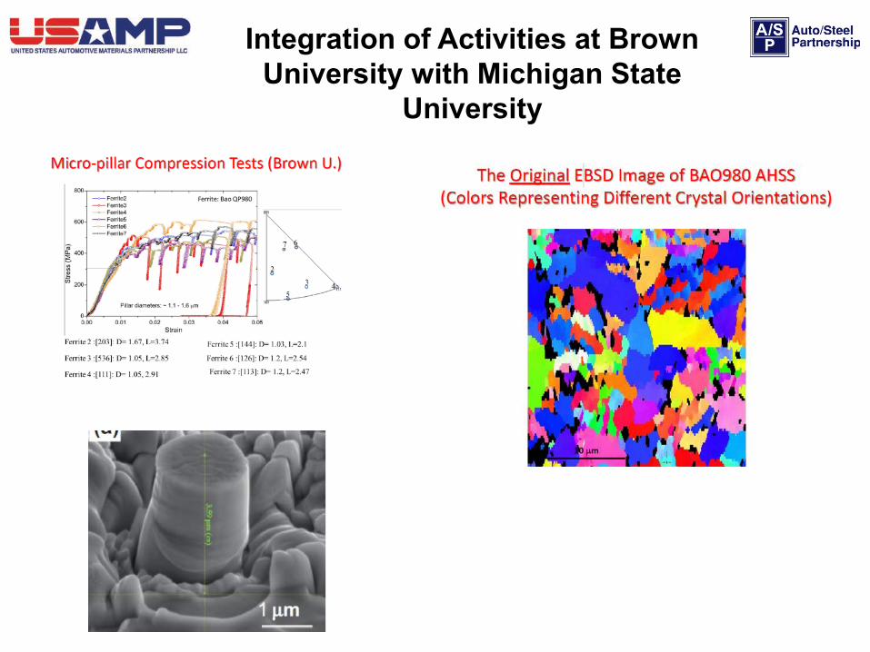
Integration of Activities at Brown University with Michigan State
University
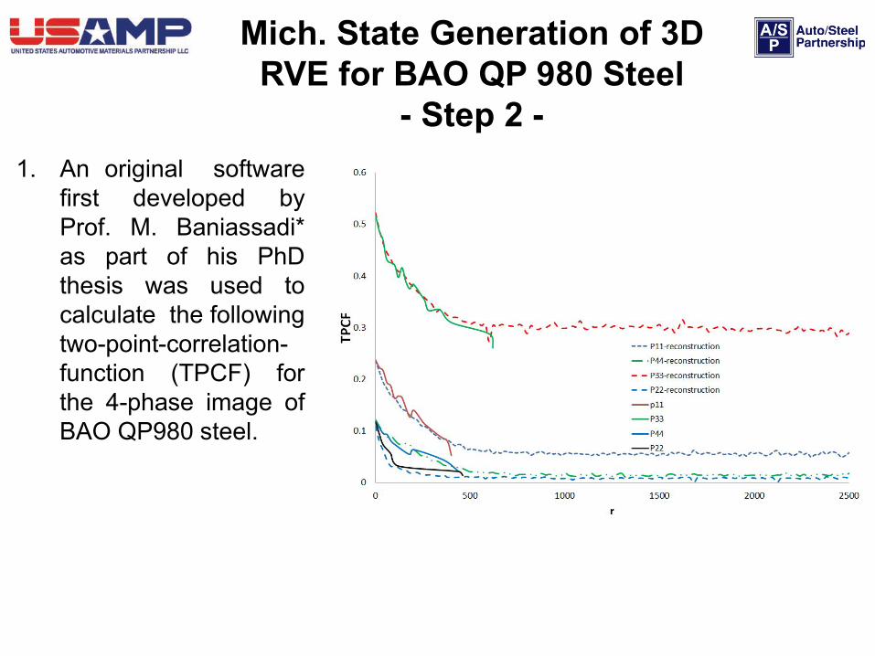
Mich. State Generation of 3D RVE for BAO QP 980 Steel
- Step 2 - 1. An original software
first developed by Prof. M. Baniassadi* as part of his PhD thesis was used to calculate the following two-point-correlation-function (TPCF) for the 4-phase image of BAO QP980 steel.
OF = objective function
100 slices
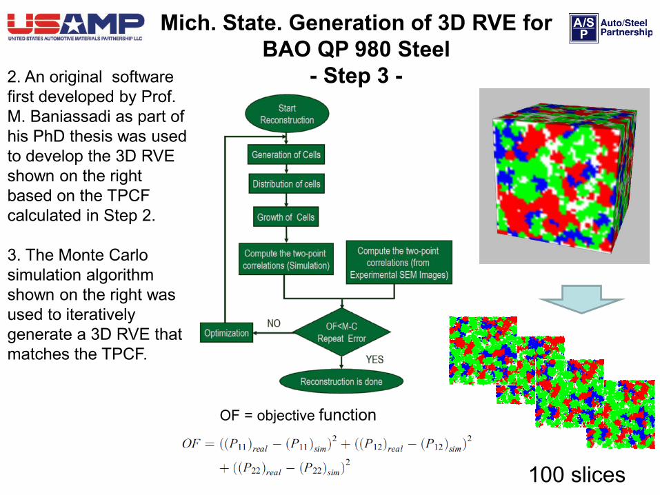
2. An original software first developed by Prof. M. Baniassadi as part of his PhD thesis was used to develop the 3D RVE shown on the right based on the TPCF calculated in Step 2.
3. The Monte Carlo simulation algorithm shown on the right was used to iteratively generate a 3D RVE that matches the TPCF.
Mich. State. Generation of 3D RVE for BAO QP 980 Steel
- Step 3 -
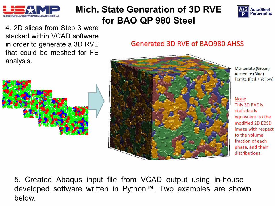
4. 2D slices from Step 3 were stacked within VCAD software in order to generate a 3D RVE that could be meshed for FE analysis.
Mich. State Generation of 3D RVE for BAO QP 980 Steel
5. Created Abaqus input file from VCAD output using in-house developed software written in Python™. Two examples are shown below.