Embed Size (px)
Citation preview
UNIVERSIDADE FEDERAL DO RIO GRANDE DO SUL
INSTITUTO DE INFORMÁTICA
CURSO DE CIÊNCIA DA COMPUTAÇÃO
RONALDO RODRIGUES FERREIRA
Integrated Model-Based Design and
Simulation of Critical Embedded Systems
Bachelor’s Thesis.
Prof. Dr. Luigi Carro
Advisor UFRGS
Eng. Patrice Thebault
Supervisor AIRBUS France SAS
Porto Alegre, October 2009.

UNIVERSIDADE FEDERAL DO RIO GRANDE DO SUL
Reitor: Prof. Carlos Alexandre Netto
Vice-Reitor: Prof. Rui Vicente Oppermann
Pró-Reitora de Graduação: Profa. Valquiria Link Bassani
Diretor do Instituto de Informática: Prof. Flávio Rech Wagner
Coordenador do CIC: Prof. João César Netto
Bibliotecária-Chefe do Instituto de Informática: Beatriz Regina Bastos Haro

3
“Esperavam nas dos fundos, e saí pela porta da frente.”
Bochincho, Jayme Caetano Braun
AGRADECIMENTOS
Agradeço minha família, a qual me suportou, com bastante carinho, dizer todo final de ano a
mesma coisa: “esse final de ano eu termino”. Muito obrigado, finalmente terminar a graduação
seria impossível sem o apoio de vocês. Incluem-se todos aqui: primos, tios, avós, irmão, pai,
mãe, povo de Uberlândia, a farofada toda.
Meus amigos do Centro de Biologia de Genômica Molecular da PUCRS, em especial:
Cladi, Felipe, Nelson, Ricardo, Nelson, Alice, Beta, André, Manoel, Paulo, e o professor Sandro
Bonatto. Com vocês aprendi o que é ciência, viciei-me em chocolates Charge, descobri que há
mais alimentos no mundo além de pastel de carne e suco de laranja e o melhor, fiz amigos para
a vida inteira em um momento que eu acabara de chegar a Porto Alegre. Obrigado pela amizade
e diversão, todos são inesquecíveis.
Meus amigos do Laboratório de Sistemas Embarcados da UFRGS, em especial: Marcio,
Marco, Caco, Mateus, Girão, Mônica, Rhod, Lisane, Julius, Emilena, Ulisses, Thomás,
Crístofer, Brião, Gabriel, Assis, Thiago, Leo, e os professores Luigi Carro, Érika Cota e Flávio
Wagner. Indescritível esse lugar, nem ao menos tentarei fazê-lo. Obrigado pela amizade,
paciência (muita), discussões, conversas e tudo o mais que eu não me lembrar de nomear.
Obrigado aos meus professores orientadores pela dedicação, apoio e amizade ao longo da minha
Iniciação Científica e após a mesma. Grande parte do profissional que hoje sou é devido ao
empenho e dedicação de vocês comigo.
Meus amigos de apartamento (aquele cafofo térmico, gelado no inverno, deserto no verão,
mal-cheiroso e levemente sujo), praticamente minha família em Porto Alegre: Marcio, Diego,
Cláudio, Oyamada, Marco e Alex. Não sei como nós nos agüentávamos; depois desses anos
todos dividindo apartamento com vocês eu comecei a acreditar que a Paz Mundial é possível
(desde que cada um lave a própria louça após o uso).
Meus amigos de dominação mundial e entrevero: Marcos, Floriano e Hugo. U$ 2.4 bilhões e
uns chineses genéricos não amedrontam cabra-macho feito a gente.
Meus amigos de Uberaba, em especial: Talita, Rodrigo, Patrícia, Diego Arantes, Raphael,
Thiago, Eduardo, Rayanne, Hernando e Diego.
Meus amigos de Porto Alegre, em especial: Gabriel, Matheus, Montanha, Zidane, Elias,
Fhilipe, Anderson, Daiane, Bruna, Carlitos, Hugo, Lola, Paulo, Otávio, Flávia, Rodolfo e
Bonerges. Porto Alegre não é a mesma sem vocês. Obrigado pela amizade.
Meus amigos da AIRBUS France, Toulouse, em especial: Steve, Miloud, Julian, Larissa,
Raphael, Éverton, Sandeep, meu supervisor Patrice Thebault, Evelyn Fabiano e todo o grupo de
Energy Simulation. Os meus quatro meses aqui foram incríveis graças à amizade de vocês.
Muito importante para a minha estadia e graduação em Porto Alegre: Lancheria do Parque
pelo almoço por R$ 6,40 e o CNPq pelos R$ 300,00 mensais. Muito obrigado.
5
TABLE OF CONTENTS
AGRADECIMENTOS .................................................................................... 4
ACRONYMS ................................................................................................. 8
FIGURES .................................................................................................... 11
TABLES ...................................................................................................... 12
ABSTRACT ................................................................................................ 13
RESUMO .................................................................................................... 14
RÉSUMÉ ..................................................................................................... 15
1 INTRODUCTION ................................................................................... 16
1.1 Motivation .............................................................................................................................. 16
1.2 Problem Statement ................................................................................................................ 17
1.3 The AIRBUS Company ......................................................................................................... 18
1.4 Text Organization.................................................................................................................. 19
2 MODEL-BASED SYSTEMS ENGINEERING ........................................ 20
2.1 Introduction to Systems Engineering .................................................................................. 20
2.2 Unified Modeling Language ................................................................................................. 21 2.2.1 Basic Principles.............................................................................................................. 21 2.2.2 UML Infrastructure ........................................................................................................ 22
2.2.2.1 Core::Abstractions .......................................................................................................... 22 2.2.2.2 Core::Basics ................................................................................................................... 23 2.2.2.3 Core::Constructs ............................................................................................................. 24
2.2.3 UML Superstructure ...................................................................................................... 24
2.3 Systems Engineering Modeling Language .......................................................................... 25
2.4 Model-Based Systems Engineering ...................................................................................... 26 2.4.1 Basic Concepts ............................................................................................................... 26 2.4.2 Harmony-SE .................................................................................................................. 27 2.4.3 OOSEM ......................................................................................................................... 27 2.4.4 RUP-SE.......................................................................................................................... 28 2.4.5 Model-Based versus Document-Centered Systems Engineering ................................... 29
2.5 Systems Engineering at AIRBUS ......................................................................................... 30 2.5.1 Two Track Unified Process ........................................................................................... 30 2.5.2 EIA 632 Standard........................................................................................................... 31 2.5.3 OSMOSE Process .......................................................................................................... 32
3 MODELING AND SIMULATION ........................................................... 35
3.1 Introduction to Modeling and Simulation ........................................................................... 35
3.2 Verification and Validation of Simulation Models ............................................................. 36
3.3 Model Simulation Accreditation and Certification ............................................................ 38
3.4 Modeling and Simulation Standard: NASA Approach ...................................................... 39
3.5 Model Simulation at AIRBUS .............................................................................................. 41 3.5.1 System Simulators ......................................................................................................... 41 3.5.2 Development, Integration and Validation of Simulation Models .................................. 42
4 PROPOSED SOLUTION ....................................................................... 44
4.1 Solution Artifacts and Requirements .................................................................................. 44
4.2 Proposed Design Flow based on SysML .............................................................................. 45
5 CASE STUDIES .................................................................................... 49
5.1 A380 Navigation System ....................................................................................................... 49 5.1.1 Navigation System Probes Embedded Avionics ............................................................ 49 5.1.2 SysML Design and Simulation and MICD Generation ................................................. 50
5.2 Primary Flight Control Computer ....................................................................................... 54 5.2.1 A340 Flight Control Computer Organization ................................................................ 54 5.2.2 Primary Flight Control Computer Equipment UML State Machine .............................. 55
6 ASSESMENT AND CONCLUSIONS .................................................... 63
6.1 Technical Evaluation ............................................................................................................. 63 6.1.1 Model Transformations .................................................................................................. 63
6.1.1.1 Understanding ................................................................................................................ 63 6.1.1.2 Completeness ................................................................................................................. 63 6.1.1.3 Specification ................................................................................................................... 63 6.1.1.4 Implementation .............................................................................................................. 64
6.1.2 SysML Design and Simulation Models ......................................................................... 64 6.1.2.1 Understanding ................................................................................................................ 64 6.1.2.2 Abstraction ..................................................................................................................... 64 6.1.2.3 Implementation .............................................................................................................. 65
6.1.3 MICD and Simulation Code Generation ........................................................................ 65 6.1.3.1 Understanding ................................................................................................................ 65

7
6.1.3.2 Completeness ................................................................................................................. 65 6.1.3.3 Implementation .............................................................................................................. 66
6.1.4 Integrated Model-Based Design and Simulation Process .............................................. 66 6.1.4.1 Understanding ................................................................................................................ 66 6.1.4.2 Completeness ................................................................................................................. 66 6.1.4.3 Suitability ....................................................................................................................... 67
6.2 Contributions and Future Work .......................................................................................... 67
REFERENCES ............................................................................................ 69
ACRONYMS
2TUP Two Track Unified Process
A/C Aircraft
A/C ICD Aircraft Interface Control Document
ACARE Advisory Council for Aeronautics Research in Europe
ADIRU Air Data Inertial Reference Unit
ADF Automatic Direction Finders
ADR Air Data Reference
AFDX Avionics Full Duplex Switched Ethernet
AMISA Advanced Model-Integrated Specifications for AIRBUS
ARINC Aeronautical Radio INCorporation
ASPIC Atelier de Simulation Pour l'Intégration et la Conception
ATA Air Transport Association
ATL ATLAS Transformation Language
ATPRO ATelier de PROduction
ATT-HDG Autotrim Heading Angle System
BDD Block Definition Diagram
BNF Backus-Naur Form
CASE Computer-Aided Software Engineering
CSV Comma Separated Values
DAMAS DAta MAnager for Specifications
DME Distance Measuring Equipment
DoD-AU Australian Department of Defence
DoD-US US Department of Defense
DSL Domain Specific Language
EADS European Aeronautic Defense and Space Company
EDYYS Simulation Department at AIRBUS France
EIS Entry-Into-Service
9
EPOPÉE Etude Prospective d’Organisation d’un Poste d’Equipage Ergonomique
FBW Fly-By-Wire
GPS Global Positioning System
IBD Internal Block Diagram
IEEE Institute of Electrical and Electronics Engineers
INCOSE International Council on Systems Engineering
INSIDE Integrated Simulation Into DEsign
IRS Inertial Reference System
ISIS Integrated Standby Instrument System
ISO International Standardization Office
ISP Prise de Pression Statique
LR Left-Recursive Parser
MARTE Modeling and Analysis of Real-Time Embedded Systems
MBSE Model-Based Systems Engineering
MDE Model-Driven Engineering
M&S Modeling and Simulation
MFP Multi-Function Probes
MFPR Model Functional Performance Requirements
MICD Model Interface Control Document
MMR Multi Mode Receiver
MOF Meta Object Facility
MS Model Specification
OAP Outside Air Temperature
OCASIME Outil de Conception Assistée de SImulation Multi-Equipements
OMG Object Management Group
OOSEM Object-Oriented Systems Engineering Method
OSMOSE One Single Methodology supported by the Open Source Environment
PRIM Primary Flight Control Computer
RA Radar Altimeter
R&T Research and Technology
ROI Return on Investment
RUP Rational Unified Process
SAS Société par Actions Simplifiée
SAO Spécification Assistée par Ordinateur
SEC Secondary Flight Control Computer

SFPR UML Profile for Simulation Functional Performance Requirements
SysML System Engineering Modeling Language
UP2A UML Profile for AIRBUS AP2633
UML Unified Modeling Language
V&V Verification and Validation
11
FIGURES
Figure 2.1: Association versus attribute ......................................................................... 24 Figure 2.2: Two Track Unified Process cycle ................................................................ 30 Figure 2.3: The EIA 632 process .................................................................................... 31
Figure 2.4: OSMOSE process cycle ............................................................................... 32 Figure 2.5: OSMOSE model package structure ............................................................. 33 Figure 3.1: AIRBUS aircraft development and simulation cycles ................................. 43 Figure 3.2: Simulation model life cycle. ........................................................................ 43
Figure 4.1: Design and simulation interactions and artifacts ......................................... 44
Figure 4.2: Design and simulation activities and artifacts of simulation development .. 45 Figure 4.3: SysML design model generation from A/C ICD ......................................... 46 Figure 4.4: SysML simulation model generation from design model and from MFPR
analysis and requirements document .............................................................................. 46 Figure 4.5: MICD generation from AP2633 compliant SysML simulation model ........ 47
Figure 4.6: Complete integrated model-based design and simulation design flow ........ 47 Figure 4.7: Simulation state machine code generation from UML State Machine
describing equipment behavior ....................................................................................... 48
Figure 5.1: A330 external navigation probes ................................................................. 50
Figure 5.2: A380 navigation systems’ A/C ICDs ........................................................... 51
Figure 5.3: SysML generation from A/C ICD performed with our tool prototype ........ 51 Figure 5.4: Generated A380 navigation systems SysML Design models ...................... 52
Figure 5.5: SFPRPort simulation local parameters selection ......................................... 52 Figure 5.6: ISIS SysML simulation model and generated SFPR dependencies ............. 53 Figure 5.7: ISIS MICD output variables and their generated joining keys .................... 53 Figure 5.8: ISIS MICD input variables and their generated joining keys ...................... 54
Figure 5.9: ISIS equipment screen ................................................................................. 54 Figure 5.10: Primary Flight Control Computer UML Equipment State Machine ......... 56 Figure 5.11: SFPR state selection ................................................................................... 56 Figure 5.12: Final UML Equipment State Machine after useless state removal ............ 57
TABLES
Table 2.1: Comparison between model-based and document-centered approaches for
Systems Engineering ...................................................................................................... 29
13
ABSTRACT
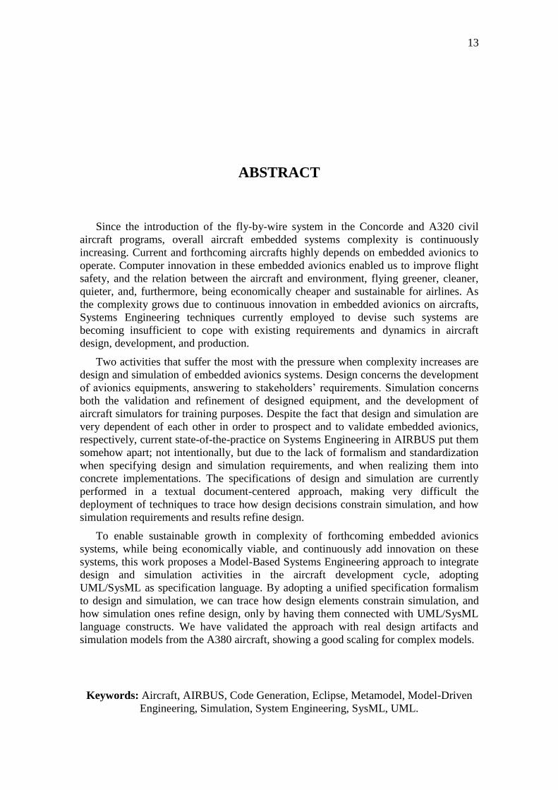
Since the introduction of the fly-by-wire system in the Concorde and A320 civil
aircraft programs, overall aircraft embedded systems complexity is continuously
increasing. Current and forthcoming aircrafts highly depends on embedded avionics to
operate. Computer innovation in these embedded avionics enabled us to improve flight
safety, and the relation between the aircraft and environment, flying greener, cleaner,
quieter, and, furthermore, being economically cheaper and sustainable for airlines. As
the complexity grows due to continuous innovation in embedded avionics on aircrafts,
Systems Engineering techniques currently employed to devise such systems are
becoming insufficient to cope with existing requirements and dynamics in aircraft
design, development, and production.
Two activities that suffer the most with the pressure when complexity increases are
design and simulation of embedded avionics systems. Design concerns the development
of avionics equipments, answering to stakeholders’ requirements. Simulation concerns
both the validation and refinement of designed equipment, and the development of
aircraft simulators for training purposes. Despite the fact that design and simulation are
very dependent of each other in order to prospect and to validate embedded avionics,
respectively, current state-of-the-practice on Systems Engineering in AIRBUS put them
somehow apart; not intentionally, but due to the lack of formalism and standardization
when specifying design and simulation requirements, and when realizing them into
concrete implementations. The specifications of design and simulation are currently
performed in a textual document-centered approach, making very difficult the
deployment of techniques to trace how design decisions constrain simulation, and how
simulation requirements and results refine design.
To enable sustainable growth in complexity of forthcoming embedded avionics
systems, while being economically viable, and continuously add innovation on these
systems, this work proposes a Model-Based Systems Engineering approach to integrate
design and simulation activities in the aircraft development cycle, adopting
UML/SysML as specification language. By adopting a unified specification formalism
to design and simulation, we can trace how design elements constrain simulation, and
how simulation ones refine design, only by having them connected with UML/SysML
language constructs. We have validated the approach with real design artifacts and
simulation models from the A380 aircraft, showing a good scaling for complex models.
Keywords: Aircraft, AIRBUS, Code Generation, Eclipse, Metamodel, Model-Driven
Engineering, Simulation, System Engineering, SysML, UML.
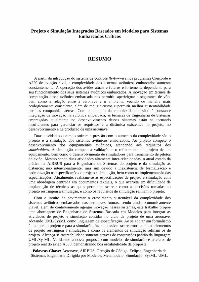
Projeto e Simulação Integrados Baseados em Modelos para Sistemas
Embarcados Críticos
RESUMO
A partir da introdução do sistema de controle fly-by-wire nos programas Concorde e
A320 de aviação civil, a complexidade dos sistemas aviônicos embarcados aumenta
constantemente. A operação dos aviões atuais e futuros é fortemente dependente para
seu funcionamento dos seus sistemas aviônicos embarcados. A inovação em termos de
computação dessa aviônica embarcada nos permitiu aperfeiçoar a segurança de vôo,
bem como a relação entre a aeronave e o ambiente, voando de maneira mais
ecologicamente consciente, além de reduzir custos e permitir melhor sustentabilidade
para as companhias aéreas. Com o aumento da complexidade devido à constante
integração de inovação na aviônica embarcada, as técnicas de Engenharia de Sistemas
empregadas atualmente no desenvolvimento desses sistemas estão se tornando
insuficientes para gerenciar os requisitos e a dinâmica existentes no projeto, no
desenvolvimento e na produção de uma aeronave.
Duas atividades que mais sofrem a pressão com o aumento da complexidade são o
projeto e a simulação dos sistemas aviônicos embarcados. Ao projeto compete o
desenvolvimento dos equipamentos aviônicos, atendendo aos requisitos dos
stakeholders. À simulação compete a validação e o refinamento do projeto de um
equipamento, bem como o desenvolvimento de simuladores para treinamento de pilotos
do avião. Mesmo sendo duas atividades altamente inter-relacionadas, o atual estado da
prática na AIRBUS para a Engenharia de Sistemas do projeto e da simulação as
distancia; não intencionalmente, mas sim devido à inexistência de formalização e
padronização na especificação do projeto e simulação, bem como na implementação das
especificações. Atualmente, realizam-se as especificações de projeto e simulação com
uma abordagem centrada em documentos textuais, o que acarreta em dificuldade de
implantação de técnicas as quais permitam rastrear como as decisões tomadas no
projeto restringem a simulação, e como os requisitos de simulação refinam o projeto.
Com o intuito de pavimentar o crescimento sustentável da complexidade dos
sistemas aviônicos embarcados nas aeronaves futuras, sendo ainda economicamente
viável, além de continuamente agregar inovação nesses sistemas, este trabalho propõe
uma abordagem de Engenharia de Sistemas Baseada em Modelos para integrar as
atividades de projeto e simulação contidas no ciclo de projeto de uma aeronave,
adotando UML/SysML como linguagem de especificação. Ao se adotar um formalismo
único para o projeto e para a simulação, faz-se possível rastrearmos como os elementos
de projeto restringem a simulação, e como os elementos de simulação refinam os de
projeto. Alcança-se rastreabilidade somente através de construções padrão da linguagem
UML/SysML. Validamos a nossa proposta com modelos de simulação e artefatos de
projeto real do avião A380, demonstrando boa escalabilidade da proposta.
Palavras-Chave: Aeronave, AIRBUS, Geração de Código, Eclipse, Engenharia de
Sistemas, Engenharia Dirigida por Modelos, Metamodelo, Simulação, SysML, UML.
15
Intégration de Conception et de Simulation Basée sur les Modèles pour
Systèmes Embarqués Critiques
RÉSUMÉ
Depuis l'introduction du système de commande de vol électrique dans les
programmes d'avions civils Concorde et A320, la complexité des systèmes embarqués
dans l’avion n’a cessé d'augmenter. Le fonctionnement des avions actuels et à venir est
fortement dépendant de l'avionique embarquée. L'innovation dans ces calculateurs nous
a permis d'améliorer la sécurité des vols, et a permis des avions plus écologiques et plus
silencieux vis-à-vis de l’environnement, tout en réduisant les coûts et en augmentant la
viabilité économique pour les compagnies aériennes. Alors que la complexité augmente
en raison de l'innovation continue dans l'avionique embarquée, les techniques
d’Ingénierie des Systèmes actuellement utilisées pour concevoir ces systèmes
deviennent insuffisantes pour faire face aux exigences existantes et à la dynamique
nécessaire dans la conception des avions, leur développement et leur production.
Les deux activités qui souffrent le plus de cette augmentation de complexité sont la
conception et la simulation de systèmes avioniques embarqués. La conception concerne
le développement des équipements avionique, pour répondre aux exigences des parties
prenantes. La simulation concerne la validation et le raffinement de la conception des
équipements, puis le développement de simulateurs d'avion utilisés pour la formation
des pilotes. En dépit du fait que la conception et la simulation sont en principe très
dépendants l’un de l’autre pour l’amélioration et validation des systèmes embarqués
avionique, les pratiques d’Ingénierie des Systèmes dans AIRBUS les ont séparées, non
intentionnellement, mais en raison de l'absence de formalisme et de normalisation
d’abord pendant la phase de spécification des exigences de la conception et de la
simulation et ensuite lors de leur implémentation concrète en phase de réalisation. Les
spécifications de conception et de simulation sont effectuées dans des documents
textuels, ce qui rend très difficile le déploiement de techniques permettant d'une part de
tracer les décisions de conception qui contraignent la simulation, et d'autre part d'utiliser
les résultats de simulation pour affiner la conception.
Afin de permettre une gestion efficace de la complexité des systèmes avioniques
embarqués à venir, tout en étant économiquement viables, et d'ajouter de l'innovation
sur ces systèmes, ce travail propose une approche Basée sur les Modèles visant à
intégrer ensemble les activités de conception et de simulation dans le cycle de
développement des avions, en utilisant UML/SysML comme langage de spécification.
En adoptant un formalisme unifié pour la spécification des exigences de la conception et
de la simulation, nous pouvons tracer comment la conception contraint la simulation, et
comment les résultats de simulation permettent d'affiner la conception. Nous avons
validé la méthode proposée en utilisant des spécifications réelles de conception et de
simulation de l'A380, montrant une bonne mise à l'échelle de la proposition.
Mots-Clés: Avion, AIRBUS, Génération de Code, Eclipse, Ingénierie Basée sur
Modèles, Ingénierie de Système, Métamodèle, Simulation, SysML, UML.
1 INTRODUCTION
This chapter presents the main motivation for this work in section 1.1, which
explains how AIRBUS can continue to setting the standards. Section 1.2 states the
problem this work address, based on the motivation we have discussed previously. To
improve the comprehension and put this work within a period of technology advances in
the Aeronautics domain, section 1.3 briefly introduces the AIRBUS Company history.
Finally, section 1.4 presents the subsequent organization of this text.
1.1 Motivation
The aircraft industry is driven by continuous innovation, being this factor decisive
for players in this industry. With innovation we can fly cheaper, greener, and with
increasingly safety and decreasing costs. Since the milestone introduction of the fly-by-
wire in Concorde aircraft, and later in the A320 (Traverse, 2004), embedded computer
systems have their place in both civil and military aircraft. Embedded systems have a
high pace of adoption in aircrafts, and the days these systems were targeted only to
aircraft control is in the past. Currently, the A380 aircraft entertainment systems,
devoted to passenger seat music and video players, as well as gaming systems, accounts
for around 30% of all wiring in the aircraft. Now modern aircrafts adjusts the interior
cabin lightning and pressure to improve passenger conform in flight – everything
controlled by embedded computer systems. Therefore, we cannot neglect the increasing
complexity we find today in current and we will face in forthcoming aircraft programs,
requiring new Systems Engineering techniques to handle this complexity if the aircraft
manufacturer wants to stay competitive and innovative.
AIRBUS internal research sees the Model-Based Systems Engineering (MBSE)
approach as a promising answer to the increasingly complexity in the forthcoming
aircraft designs. There are research projects currently in AIRBUS studying and
developing methods for the adoption of UML/SysML as the formalism to specify
avionics systems.
The INtegrated Simulation Into DEsign (INSIDE) project is an internal research and
technology (R&T) project aiming at foreseeing new systems design techniques and
processes for avionics systems (AIRBUS, 2008b). In AIRBUS, the following activities
compose system design: formalize specifications; generate the system model –
executable specification; test the specification with simulation; analyze results; refine
specifications with gathered knowledge from results analyzes. We iteratively perform
these activities until results found are acceptable.
Current systems design simulation platform is the OCASIME simulator (we will
present it in subsequent chapters), which is integrated with other simulators, enabling

17
model reuse among these simulation platforms. Despite its well-founded simulation
platform, OCASIME does not integrate the system validation framework, increasing
validation time in the design life cycle. In addition, some models have a long
compilation time, incurring in wasted time when these models have errors or are not
acceptable. Another problem is that OCASIME test procedures are not reusable by other
simulation platforms, increasing test time.
Thus, the main INSIDE goals are, in short-term, to improve the OCASIME
simulation platform, and, in long-term, to improve system design and simulation
integration. We can accomplish this integration by providing a multi-specification-
formalisms platform, enabling to model each system component with the best suitable
formalism (not only Simulink and SCADE, as today); enabling real-time
interoperability between distinct simulation platforms, reducing turn-around time
between simulators; sharing of test scenarios between distinct simulation platforms,
what reduces test efforts while improving quality. The current adopted language for
specifying simulations is UML/SysML. This work is in the frame of INSIDE.
The Advanced Model-Integrated Specifications for Airbus (AMISA) is also an
internal R&T, but differently from INSIDE that is targeted to system simulation,
AMISA is targeted to systems design (AIRBUS, 2008c). AMISA will be partially
deployed in the A350 aircraft program, but it is intended to be widely deployed in the
A30X program (A320 program successor), as well as other model-based approaches.
AMISA also adopts UML/SysML as specification language, and Simulink as low-level
behavior implementation language. AMISA adopts Telelogics Rhapsody as its CASE
tool, integrating automatically with Telelogics DOOR tool for requirements
management, and with Simulink through its S-Functions (S-Functions are external
behavior to the Simulink environment. Actually, it defines C code function
implemented outside Simulink). INSIDE adopts TOPCASED as its CASE tool. As
MBSE techniques are yet in research stage, AIRBUS does not have a closed decision in
which tools to adopt. The main AMISA goal is to increase system maturity in Entry-
Into-Service (EIS) for a new devised aircraft program, correcting some problems to
future aircrafts development identified in the A380 program regarding this issue.
1.2 Problem Statement
Concerning the development of design and simulation activities, the pace of
innovation poses big challenges to forthcoming projects, and we foresee that current
Systems Engineering techniques will not be suitable to handle this new complexity.
AIRBUS identified some of these problems based on gathered knowledge from the
A380 and previous programs (AIRBUS, 2008c):
Recurring problems due to misinterpretations of specifications between
development teams. The main cause to that is the current way AIRBUS
writes specifications, based on text documents and requirements;
Late identification of errors in the specifications, because currently they are
not completely executable. This postpones errors finding when we integrate
developed avionics equipments onto simulators;
Insufficient model exchange with AIRBUS suppliers.
Regarding the problems above, it is desirable to have a well-defined and
unambiguously modeling approach for specifying system functions, behaviors, and
performance, allowing for early model validation by executing these models, as well as
to ensure interoperability between devised models by defining common model
interfaces which modeling teams can rely on.
Specific to simulation design, the problems are:
Currently, the simulation model code generator only accepts Simulink,
SCADE, SAO, and C code. If the system is not specified with these
formalisms, they cannot be validated with the existing simulation platform;
Simulation model generation is not fully integrated with its validation,
requiring the Simulation Model Designer to use two distinct environments to
perform model generation and validation;
Model generation can be very time-consuming, requiring in some cases a
couple of days to generate model code. If we consider an iterative process
cycle to correct model errors, these days can become weeks or months until
the model reaches stability;
The simulation platform is not too robust, being quite closed to internal
AIRBUS employees, preventing simulation deployment to suppliers;
Another issue is that simulation and design activities are somehow apart in the
development process, while ideally they should be very connected. The main problem is
that it is quite difficult to trace what design elements a simulation element is simulating.
This can incur into redundancies between design and simulation elements.
Simulation in AIRBUS has advanced a lot since its first deployment around twenty
years ago. However, clearly, forthcoming requirements and innovation in new aircrafts
demand to improve current processes.
1.3 The AIRBUS Company
A consortium of European industries formed the Airbus Company to compete with
North American companies such as Boeing. In the mid-60s, tentative negotiations began
regarding a European joint venture – some European companies have discussed such a
possibility. At the 1965 Paris Air Show, some major European commercial airline
companies discussed the requirements for a new passenger aircraft, capable of
transporting more than one hundred customers on short to middle distances at a low
cost. In 1966, first formed partners were Sud Aviation from France, Deutsch Airbus
from Germany, and Hawker Siddeley from the United Kingdom; the three home
governments of each company listed above also formed the consortium.
In early 1967, this consortium has launched the A300 brand, and has evolved this
aircraft to have 320 passenger seats, being a twin-engine aircraft. In middle July 1967,
the three cited governments agreed to start the project. Sud Aviation was in charge of
cockpit and flight control systems, as well as fuselage’s lower central section. Deutsch
Airbus was in charge of forward and read fuselage sections and upper centre section.
Fokker from Netherlands was in charge of flaps and spoilers systems; and CASA (not
yet a full consortium member) from Spain was in charge of horizontal tail plane. In
December 1970, the consortium constituted Airbus Industrie as an Economic Interest
Group.
19
In early 1990, the former AIRBUS CEO wanted to constitute the Company as a
conventional one, but due to difficulties in integrating and measuring the economical
assets of Airbus at that time, he postponed this initiative until 2000. In 2000, all
companies merged, forming the European Aeronautic Defense and Space Company
(EADS), enabling the new constitution process.
The consortium constituted Airbus in 1970 and its headquarters are located in
Toulouse, France. It has around 57,000 employees in the World, divided in four
European sites (France, Germany, Spain and the United Kingdom), as well as in five
main subsidiaries (North America, China, India, Japan and Transport International). It
has currently 270 clients worldwide and has over 5,400 aircrafts in service.
1.4 Text Organization
This work is organized as follows:
Chapter 2 introduces the Systems Engineering domain, its concepts, and
current approaches for model-based systems engineering. It reviews the basic
UML concepts we use throughout this work, and briefly compares model-
based versus document-centered approaches for Systems Engineering. It
ends with a presentation of the Systems Engineering approach in AIRBUS;
Chapter 3 introduces the Simulation domain, its concepts, and current
standards for simulation of critical hardware and software. It discusses
verification and validation of simulation models, and Model Simulation
accreditation and certification. It ends with a presentation of System
Simulation in AIRBUS;
Chapter 4 presents our proposed solution to the problems discussed in this
chapter, in section 1.2;
Chapter 5 presents the case studies we have performed to evaluate and
validate our proposed approach;
Chapter 6 draws our technical assessment regarding the proposed approach
and the case studies performed, and conclusions concerning the next steps to
make our approach better.
2 MODEL-BASED SYSTEMS ENGINEERING
This chapter introduces the main Model-Based Systems Engineering (MBSE)
concepts related with this work and how Systems Engineering is at AIRBUS. Section
2.1 introduces what is Systems Engineering and its main concepts and terminology.
Section 2.2 introduces the Unified Modeling Language (UML), as well as its main
constructs used in this work, while section 2.3 presents the Systems Engineering
Modeling Language (SysML), the UML’s counterpart targeted to Systems Engineering.
Section 2.4 presents some available methodologies supporting the Model-Based
Systems Engineering approach. Finally, section 2.5 presents the Systems Engineering
approach that both INSIDE project and this work adopt.
2.1 Introduction to Systems Engineering
This section introduces Systems Engineering basic concepts and how they relate to
this work. In addition, it presents one of the most used Systems Engineering processes
up to now, the IEEE 1220. Section 2.5.2 presented the EIA 632 process, which together
with IEEE 1220 are the most well-know Systems Engineering processes in industry.
A system is a set of arrangement of related elements [people, products (hardware and
software) and processes (facilities, equipment, material, and procedures)], and whose
behavior satisfies operational needs and provides for the life cycle sustainability of the
products. In addition, it contains the people required to develop, produce, test,
distribute, operate, support, or dispose the system (IEEE, 2005). By this definition, the
main difference of a system from Systems Engineering to Software Engineering
perspective is that a system may compose hardware and software components, being
these two different architectures well described in the system’s specifications. In
Software Engineering, usually the underlying hardware is not a concern, only when we
consider Embedded Software (Ferreira, 2009).
A system is a composition of related systems, which together provide some useful
service to the environment through its published interfaces, as well as consume services
from other systems from this environment. An environment can be either software or
hardware systems, or even a human user. The general system hierarchy is: system,
product, subsystem, assemblies, components, subcomponents, and parts. Several
products can compose a system, and a product can define several subsystems, which are
in turn composed of several components (IEEE, 2005).
A life cycle is the system or product evolution initiated by perceived stakeholder
needs through the disposal of the products (IEEE, 2005). The following functional
processes compose the usual Systems Engineering life cycle:

21
Development, which is the planning and execution of system and subsystem
definition tasks required to evolve the system from stakeholder needs to
product solutions and their life cycle processes.
Manufacturing, composing tasks, actions, and activities for fabrication and
assembly of engineering test models, prototypes, and production of product
solutions and their life cycle process products.
Test, composing tasks, actions, and activities for evaluating product solutions
and their life cycles processes to measure specification conformance or
stakeholder satisfaction.
Distribution, composing the tasks, actions, and activities to initially transport,
assemble, install, test, and check out products to effect proper transition to
users, operators or consumers.
Operations, tasks, actions, and activities associated with the use of the
product or a life cycle process.
Support, involves tasks, actions, and activities providing maintenance,
support material and facility management sustaining operations.
Training, measurable tasks, actions, and activities required to achieve and
maintain the knowledge, skills, and abilities necessary to perform efficiently
and effectively operations, support, and disposal throughout the system life
cycle.
Disposal, tasks, actions, and activities to ensure that disposal or recycling of
destroyed or irreparable consumer and life cycle processes and by-products
comply with applicable environmental regulations and directives.
(IEEE, 2005)
The Systems Engineering process usually composes a set of activities: requirement
analysis, requirements validation, functional analysis, functional verification, synthesis,
and design verification. These activities are well known in the Software Engineering
context, and they are not discussed further here. The main difference between the
Systems and Software Engineering is that in the former we consider in addition to
software, hardware portions. For details, refer to IEEE (2005).
2.2 Unified Modeling Language
This section discusses the UML metamodel constructs used during through this
work. Thus, it assumes that the reader has some user knowledge on the Unified
Modeling Language (UML) and its basic diagrams (mainly class, sequence, states,
activities, and use cases) and on the class-based Object-Oriented paradigm (the
difference between a class and an instance). We refer interested readers aiming at
earning good knowledge on UML to Larman (2004) and on Object-Oriented approaches
to Craig (2007).
2.2.1 Basic Principles
Currently on its version 2.2, two documents specify the UML language, UML
Infrastructure (OMG, 2009a) and UML Superstructure (OMG, 2009b). The
Infrastructure document specifies the UML core elements, used to specify several
OMG specifications, including UML itself. The Superstructure specifies more detailed
elements, such as behavior and interactions; usually, it is not reused by other OMG
specifications.
UML was devised to meet some requirements (OMG, 2009a): modularity, having
strong cohesion and being loosely coupled; layering, to separate UML specification
from metamodels and models, as well as to enable different abstraction levels of the
same model; partitioning, enabling smooth UML metalanguage extension; extensibility,
through the use of profiles, having, thus, a built-in support for several application
domains; and reuse, enabling new specifications to use the UML concepts coherently.
The UML Infrastructure documents specify the Core and Profiles package, which
contains the PrimitiveTypes, Abstractions, Constructs, and Basic Packages.
PrimitiveTypes contains the primitive types in UML: Boolean, Integer, String, and
UnlimitedNatural. Abstractions package contains metaclasses designed to be specialized
by other metamodels reusing the UML Infrastructure. Constructs define metaclasses
related to Object-Oriented modeling, mainly used to implement the UML kernel
constructs. Basic defines the constructs enabling the UML serialization to XMI. Profiles
package enables to tailor specific domain model concepts into existing ones in the target
metamodel.
The UML language also defines the four-layer metamodel hierarchy, used to specify
how model levels are interconnected, enabling the concept of metamodeling. The four-
layers hierarchy is composed by: M3 layer, which corresponds to the meta-metamodel,
defined by the Meta Object Facility (MOF) (OMG, 2006a) specification; M2 layer,
which corresponds to the metamodel, defined by the UML language specification; M1
layer, defined by some user application model, expressed by the adopted metamodel
language, in this example the UML one; and M0 layer, which is the actual runtime
instance of the M1 layer.
When devising the UML metamodel, OMG has adopted some formal techniques,
aiming at some goals, to know: correctness, by defining well-formed rules and methods
to validate a model; precision, eliminating syntactic and interpretation ambiguity;
conciseness, avoiding non-necessary and superfluous constructs; consistency, by
guaranteeing that metamodel constructs do not create contradictions; and
understandability, improving the readability and understanding of the specification,
preferring to apply a less formal mechanism when it improves readability over the
formal one. Due to this last design decision, UML is considered a semiformal language.
In addition, to some constructs more related with implementation issues, the UML
specification can specify this case as a semantic variation point, being the correct
specification in charge of who implements this construct in the target execution
environment.
2.2.2 UML Infrastructure
Two packages compose the UML Infrastructure (OMG, 2009a), Core and Profiles,
decomposed further in more sub packages, as presented above. This section presents the
most important UML Infrastructure constructs to this work.
2.2.2.1 Core::Abstractions
The UML metaclasses important to this work are Classifier, Feature,
StructuralFeature, BehavioralFeature, Element, InstanceSpecification, and Slot.
23
Classifier defines a namespace that can contain features; it is some sort of a
named container for features. Classifier is an abstract metaclass.
Feature is an abstract metaclass defining a behavioral or structural feature of
a Classifier; it is only used to unify methods accessing Features, enabling to
handle both structural and behavioral ones.
StructuralFeature is a typed feature of a classifier specifying that this
classifier has a structure, which can be instantiated during runtime, being
allocated into some slot. StructureFeature is an abstract metaclass.
BehavioralFeature is an abstract metaclass that specifies some behavior
attached to the Classifier this BehavioralFeature is contained.
Element is an abstract metaclass with no super class, being the UML
metamodel root class.
InstanceSpecification is a concrete metaclass defining some model entity,
partially or even completely. This definition is made by assigning values
(InstanceValue metaclass) to the entity’s slots. InstanceSpecification is used
to represent the modeled system during runtime, e.g. an
InstanceSpecification of the Classifier
Class represents an element of the model domain, and its instance is an
object. Slot specifies that some StructuralFeature owned by an
InstanceSpecification owns a value, e.g. the Slot of a Class’ Property is a
value assigned during runtime.
2.2.2.2 Core::Basics
The important metaclasses in this package are: NamedElement, Type,
TypedElement, Class, Operation, and Property.
A NamedElement is an Element that may have a name.
Type is an abstract metaclass that introduces a typing system, being the type
of a TypedElement.
TypedElement is an abstract metaclass extending NamedElement, adding a
Type to it.
Class extends Type, enabling itself to have a Type with properties (Class
attribute ownedAttribute[*]) and operations (Class attribute
ownedOperation[*]), and to introduce a type hierarchy through the
superClass[*] attribute – note that multiple inheritance is possible, and how
to handle this is a semantic variation point.
An Operation is a kind of container to some behavior, being owned only by
instances of Class. An Operation extends both TypedElement and
MultiplicityElement, and may have a list of parameters (Operation attribute
ownedParameter[*]).
A Property is a TypedElement, being an attribute of a Class. The strange is
that on the UML Infrastructure is possible for an attribute to exist without a
container class, given its class[0..1] attribute has the lower bound set to 0
(OMG, 2009a, p.98). The UML Infrastructure document does not specify
why this is possible.
2.2.2.3 Core::Constructs
The important metaclasses in this package are DirectedRelationship, and
Association.
DirectedRelationship is a Relationship in which it is possible to distinguish
between source and target Elements, through the attributes
source[1..*]::Element and target[1..*]::Element. Note that any kind of
metaclass can be a source or target within a DirectedRelationship.
Association defines a set of tuples, whose values refer to typed instances.
Association is a Classifier, thus it can be instantiated, and we call its
instances links. This is sometimes a source of confusion, and it is worthy of a
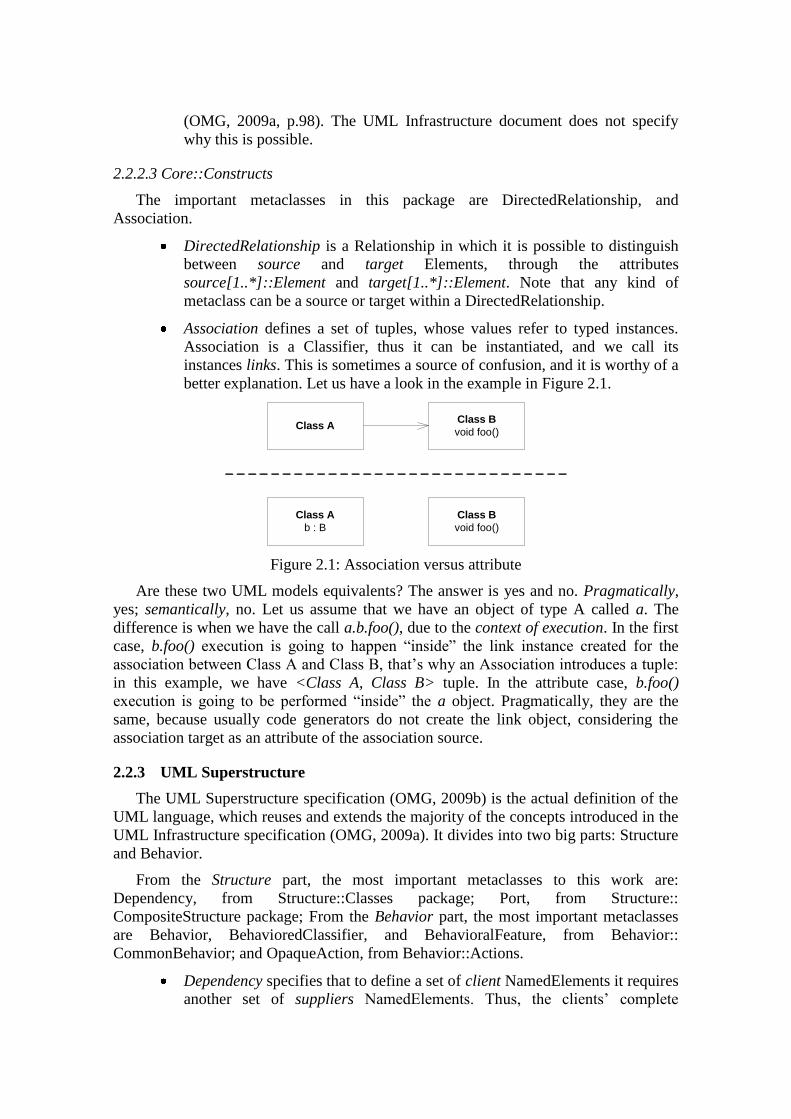
better explanation. Let us have a look in the example in Figure 2.1.
Class AClass B
void foo()
Class A
b : B
Class B
void foo()
Figure 2.1: Association versus attribute
Are these two UML models equivalents? The answer is yes and no. Pragmatically,
yes; semantically, no. Let us assume that we have an object of type A called a. The
difference is when we have the call a.b.foo(), due to the context of execution. In the first
case, b.foo() execution is going to happen “inside” the link instance created for the
association between Class A and Class B, that’s why an Association introduces a tuple:
in this example, we have <Class A, Class B> tuple. In the attribute case, b.foo()
execution is going to be performed “inside” the a object. Pragmatically, they are the
same, because usually code generators do not create the link object, considering the
association target as an attribute of the association source.
2.2.3 UML Superstructure
The UML Superstructure specification (OMG, 2009b) is the actual definition of the
UML language, which reuses and extends the majority of the concepts introduced in the
UML Infrastructure specification (OMG, 2009a). It divides into two big parts: Structure
and Behavior.
From the Structure part, the most important metaclasses to this work are:
Dependency, from Structure::Classes package; Port, from Structure::
CompositeStructure package; From the Behavior part, the most important metaclasses
are Behavior, BehavioredClassifier, and BehavioralFeature, from Behavior::
CommonBehavior; and OpaqueAction, from Behavior::Actions.
Dependency specifies that to define a set of client NamedElements it requires
another set of suppliers NamedElements. Thus, the clients’ complete
25
definition is only possible with all their suppliers. Dependency has no
runtime semantics; it completely defines itself in terms of model elements,
not instances. UML enables models to specialize the semantics of
Dependency, making it most appropriate for the model’s specific domain.
BehavioredClassifier specializes Classifier metaclass enabling a Classifier to
own behaviors contained in its namespace. BehavioredClassifier has two
main attributes: ownedBehavior[0..*], which is the set of behaviors within
the BehavioredClassifier namespace; and classifierBehavior[0..1], which is
the behavior of the BehavioredClassifier, being this attribute a subset of
ownedBehavior[0..*]. The behavior specified in classifierBehavior attribute
executes just after the BehavioredClassifer instantiation.
Behavior is the specification of how its context Classifier changes over time.
This behavior specification can be an atomic, emergent, or even an
illustration of a subset of real execution. The behavior is said to be atomic if
it is contained in only one implementation, e.g. within an Activity. The
behavior is emergent if its specification depends on the interaction of more
than one BehavioredClassifiers, usually being specified by a
CollaborationUse. The illustration is the case when the behavior is specified
with a Sequence Diagram, which is actually a scenario of execution, not its
complete specification. The Behavior has two main attributes:
specification[0..1]::BehavioralFeature, being the behavior specification
itself; and context[0..1]::BehavioredClassifier, which defines where this
behavior is going to be executed (recall the example from Figure 2.1,
Association versus Attribute).
BehavioralFeature declares and implements a behavior. The
BehavioralFeature specifies, thus, which behavior is executed when the
BehavioralFeature is invoked. It has one main attribute,
method[0..*]::Behavior, which defines the behaviors executed when the
BehavioralFeature is invoked. The formal parameter list match against a
method is done in the BehavioralFeature context, but how this is done is a
semantic variation point, as some languages employ covariance, while others
contra-variance.
OpaqueAction is an Action that is used as a placeholder for an
implementation. An OpaqueAction enables to implement an Action in a
language apart from UML, for example Java or C++, as long as this language
source-code has text format.
2.3 Systems Engineering Modeling Language
This section briefly introduces the Systems Engineering Modeling Language
(SysML) on a user-centered approach. We are not going to discuss its metamodel, even
because metamodel constructs used in this work are fairly the same from UML, which
section 2.2 presented. For a gentle introduction to SysML, we refer interested readers to
Weilkiens (2008).
Apart from UML which was designed to model software systems, SysML (OMG,
2008b) was designed to smoothly handle systems composed by hardware, information,
and so on, not only software-based systems. To do so, it reuses some portions of the

UML 2 language (OMG, 2009a), and extends it to better represent concepts from the
systems engineering domain.
The most important changes in SysML from UML are (Weilkiens, 2008):
Classes are called Blocks, and the Class diagram was changed to Block
Definition Diagram (BDD);
The Composite diagram was changed to Internal Block Diagram (IBD);
It is possible to specify item flow within an IBD;
Support for continuous functions through actions and object nodes in
Activity diagram;
Introduction of two new diagrams, Requirements, and Parametric.
The Requirement diagram defines a way to express system requirements in the
diagram, and to manage all the requirement life cycle through its defined dependencies:
derive requirement (the client was derived from the supplier); satisfy (the set of clients,
which are actually model elements, a Block for example, satisfies the supplier
requirement); copy (the client requirement is the same as the supplier, but its name and
unique identification); verify (the client test case is used to check the supplier
consistency); refine (the client is a model refine of the supplier); and trace (a very weak
dependency, it is used only to link the supplier requirement with a client model element
when the other dependencies presented are not suitable to represent their relationship)
(Weilkiens, 2008).
The Parametric diagram enables to parameterize the properties of some blocks,
creating parametric functions with them. A parametric function is a function that is
calculated given some parameters, which are properties in the model. For example, y =
ax + b is a parametric function. These parameters are specified within Constraint
Blocks. A Constraint block defines some constraints in its properties, e.g. if a Constraint
block has an integer property a, than a valid constraint would be a > 6 (Weilkiens,
2008).
It is important to define model view and viewpoints. A view is a representation of
the entire system, based on a selected viewpoint. A viewpoint specifies the structure of a
view based on a set of stakeholders. In other words, a view is an abstraction of the entire
subsystem, where the viewpoint defines this abstraction, depending on the stakeholders
of interest for a view. In this way, it is possible to create different representations of the
same system for different presentation purposes (Weilkiens, 2008).
2.4 Model-Based Systems Engineering
This section presents the basic concepts on Model-Based Systems Engineering
(MBSE), as well as some well-know methodologies supporting MBSE. This section is
based on a survey from the INCOSE Focus Group on MBSE (Estefan, 2007). Finally, in
section 2.4.5 it presents a comparison between the current state-of-the-practice and
model-based approaches for Systems Engineering.
2.4.1 Basic Concepts
We find five important concepts in MBSE: process, method, tool, methodology, and
environment.
27
A process is a logical sequence of tasks performed to achieve a particular
objective. A process defines what is to be done, without specifying how each
task is performed.
A method consists of techniques for performing a task, thus it defines how
each task is going to be realized.
A tool is an instrument that, when applied to a particular method, can enhance
the efficiency of the task, provided it is applied properly and by somebody
with proper skills and training.
A methodology is a collection of related processes, methods, and tools. It is
essentially a guide and can be thought of as application of related processes,
methods, and tools to a class of problems that all have something in common.
An environment consists of surroundings, external objects, conditions, or
factors that influence the actions of an object, individual person or group.
These conditions can be social, cultural, personal, physical, organizational, or
functional. The purpose of a project environment should be to integrate and
support the use of tools and methods on that project. Thus, it enables (or
disables) the what and the how.
(Estefan, 2007)
2.4.2 Harmony-SE
I-Logix (now Telelogics) has created the Harmony-SE methodology to support
Systems Engineering with SysML. Its improvement is mainly due to its integration with
a strong requirement management tool, in this case Telelogic DOORS. It had a good
acceptance because the US Department of Defense (DoD) used a tool called Software
Architect from Popkin Software Company, which was bought by Telelogic, and
integrates with Harmony-SE. Harmony-SE was designed to be vendor-neutral, but it is
only supported by Telelogic Rhapsody tool.
The key objectives that Harmony-SE methodology accomplishes are:
Identify/derive required system functionality;
Identify associated system states and modes;
Allocate system functionality/modes to a physical architecture.
As usual on SysML, Harmony-SE is service-oriented, and uses SysML blocks to
represent the system structure. The communication between blocks is given with service
requests, which induces some state (or mode in Harmony-SE terminology) in the
requested block. Sequence Diagrams represents the communication between system
structures, and the system structure with internal block definition diagrams.
The interesting is that every Harmony-SE element traces and synchronizes with a
requirement on the requirements repository using Telelogic DOORS. For a more
detailed introduction to Harmony-SE, refer to (Estefan, 2007).
2.4.3 OOSEM
The Object-Oriented Systems Engineering Method (OOSEM) employs a top-down
approach for specification, verification, analysis, design and development, where the
SysML language supports all these levels (Estefan, 2007). By adopting SysML as its
implementing language, OOSEM methodology integrates smoothly with current Object-
Oriented techniques. The OOSEM key objectives are the following, extracted from
(Estefan, 2007):
Capture and analysis of requirements and design information to specify
complex systems;
Integration with Object-Oriented software, hardware, and other engineering
methodology;
Support for system-level reuse and design evolution.
Three components compose the OOSEM structure:
Systems Engineering Foundation: contains the systems engineering
processes defining how requirements must be elicited;
Common Object-Oriented System Engineering: top-down and recursive
layer, it is use-case driven based on previous elicited requirements. Defines
black and white box components, using Object-Oriented concepts, and is
expressed with UML/SysML languages. It depends on Systems Engineering
Foundation layer;
OOSEM Unique: concerns the system activities, such as business model,
context where the system is going to be deployed, system/logical
decomposition, partitioning, allocation, and further system high-level
activities. Is depends on Common Object-Oriented System Engineering
layer.
The three previous cited key objects are unrolled into the following activities, based
on the V model (Forsberg, 1991):
Analyze stakeholder requirements;
Define system requirements;
Define logical architecture;
Synthesize candidate allocated architecture;
Optimize and evaluate design alternatives;
Validate and verify the overall system.
2.4.4 RUP-SE
The Rational Unified Process for Systems Engineering (RUP-SE) is based on the
well-know software development RUP process, incrementing it to deal with systems
specification, analysis, design and development (RATIONAL, 2002). RUP is based on
content-elements, describing what must be produced in each RUP cycle. These cycles
can be represented by the well know RUP’s whale chart.
All iterations in the RUP life cycle have seven disciplines: business modeling,
requirements, analysis and design, implementation, test, and deployment. RUP-SE
extends RUP by defining new roles, by including for example the systems engineer;
new artifacts related to systems engineer non-function requirements, such as security,
training, and logistics; by adding the concepts of model level, view and viewpoints. A
model level groups model element with similar level of details – it does not group
29
abstraction levels. RUP-SE offers more scalability due the concept of viewpoint from
SysML, enabling to provide the same model with different presentation details for
distinct groups of stakeholders, without replicating model elements and it offer built-in
support for non-functional requirements. IBM Company through its IBM Rational
Software Suite offers tool support for RUP-SE.
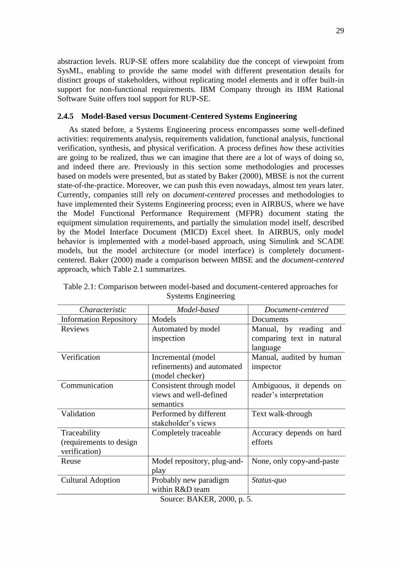
2.4.5 Model-Based versus Document-Centered Systems Engineering
As stated before, a Systems Engineering process encompasses some well-defined
activities: requirements analysis, requirements validation, functional analysis, functional
verification, synthesis, and physical verification. A process defines how these activities
are going to be realized, thus we can imagine that there are a lot of ways of doing so,
and indeed there are. Previously in this section some methodologies and processes
based on models were presented, but as stated by Baker (2000), MBSE is not the current
state-of-the-practice. Moreover, we can push this even nowadays, almost ten years later.
Currently, companies still rely on document-centered processes and methodologies to
have implemented their Systems Engineering process; even in AIRBUS, where we have
the Model Functional Performance Requirement (MFPR) document stating the
equipment simulation requirements, and partially the simulation model itself, described
by the Model Interface Document (MICD) Excel sheet. In AIRBUS, only model
behavior is implemented with a model-based approach, using Simulink and SCADE
models, but the model architecture (or model interface) is completely document-
centered. Baker (2000) made a comparison between MBSE and the document-centered
approach, which Table 2.1 summarizes.
Table 2.1: Comparison between model-based and document-centered approaches for
Systems Engineering
Characteristic Model-based Document-centered
Information Repository Models Documents
Reviews Automated by model
inspection
Manual, by reading and
comparing text in natural
language
Verification Incremental (model
refinements) and automated
(model checker)
Manual, audited by human
inspector
Communication Consistent through model
views and well-defined
semantics
Ambiguous, it depends on
reader’s interpretation
Validation Performed by different
stakeholder’s views
Text walk-through
Traceability
(requirements to design
verification)
Completely traceable Accuracy depends on hard
efforts
Reuse Model repository, plug-and-
play
None, only copy-and-paste
Cultural Adoption Probably new paradigm
within R&D team
Status-quo
Source: BAKER, 2000, p. 5.
The only “drawback” is the requirement to have tool support, but this can be easily
accomplished, and several tools were presented to that. Thus, the initial effort to
implement a MBSE approach probably offers an excellent Return on Investment (ROI).
2.5 Systems Engineering at AIRBUS
Systems Engineering, in a broad sense, is the use of well-defined methodology
(engineering part) to design and develop products that together offer a valuable service
to some user (system part). The Airbus Avionics and Simulation Department defined a
System Engineering process based on a model-driven approach and SysML called
OSMOSE (One Single Methodology supported by the Open Source Environment). The
OSMOSE process focuses in defining equipment requirements and produces design
artifacts in a more formal fashion. Within OSMOSE, a requirement specification is
described with SysML. OSMOSE was created based on the EIA632 standard and on the
Two Track Unified Process (2TUP).
2.5.1 Two Track Unified Process
The well know Unified Process (UP) is a development process that uses as its
working language the UML. It is an iterative, incremental, and use case-driven process.
Several CASE tools support it, such as IBM Rational Rose, and have a very successful
history in the software development industry. The 2TUP (Roques, 2003) extends UP by
adding one development branch in addition to the existing functional requirements one.
The added branch deals with technical constraints that describe some operational
constraints such as software specification, underlying hardware and operating
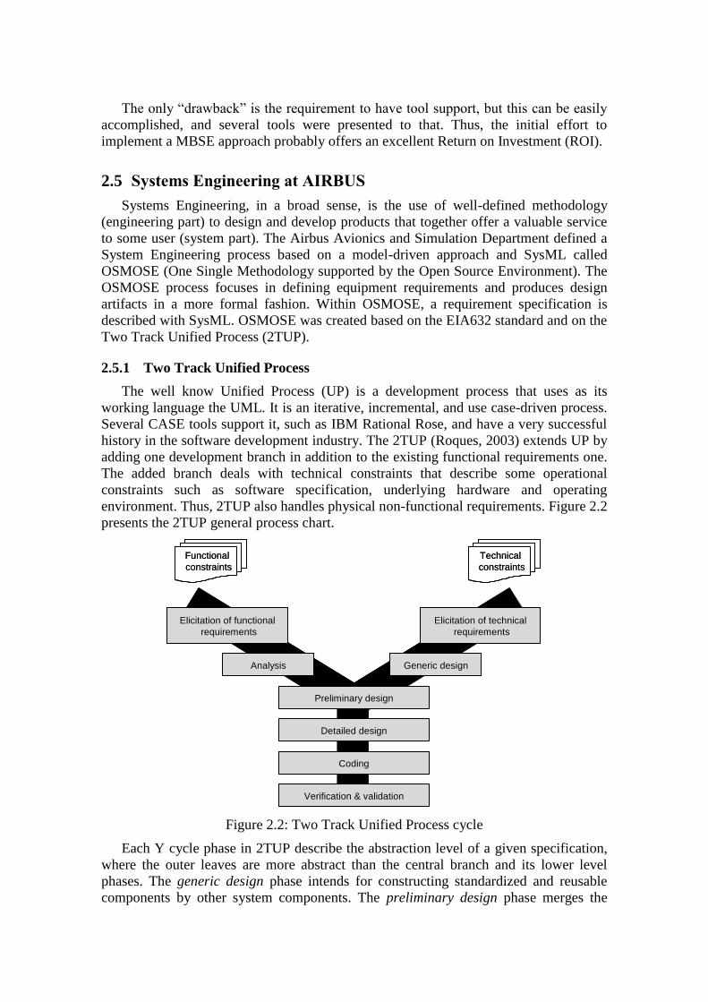
environment. Thus, 2TUP also handles physical non-functional requirements. Figure 2.2
presents the 2TUP general process chart.
Figure 2.2: Two Track Unified Process cycle
Each Y cycle phase in 2TUP describe the abstraction level of a given specification,
where the outer leaves are more abstract than the central branch and its lower level
phases. The generic design phase intends for constructing standardized and reusable
components by other system components. The preliminary design phase merges the
Elicitation of functional
requirements
Elicitation of technical
requirements
Analysis Generic design
Preliminary design
Detailed design
Coding
Verification & validation
Functional
constraints
Technical
constraints
Elicitation of functional
requirements
Elicitation of technical
requirements
Analysis Generic design
Preliminary design
Detailed design
Coding
Verification & validation
Functional
constraints
Technical
constraints
31
functional and non-functional branches, resolving conflicts between them if any. The
detailed design phase assesses how to create actual components from preliminary
design specification. The remaining two stages concerns components construction and
its proper validation. 2TUP was firstly designed to deal with Information Systems, thus
the OSMOSE methodology had adapted it for Systems Engineering.
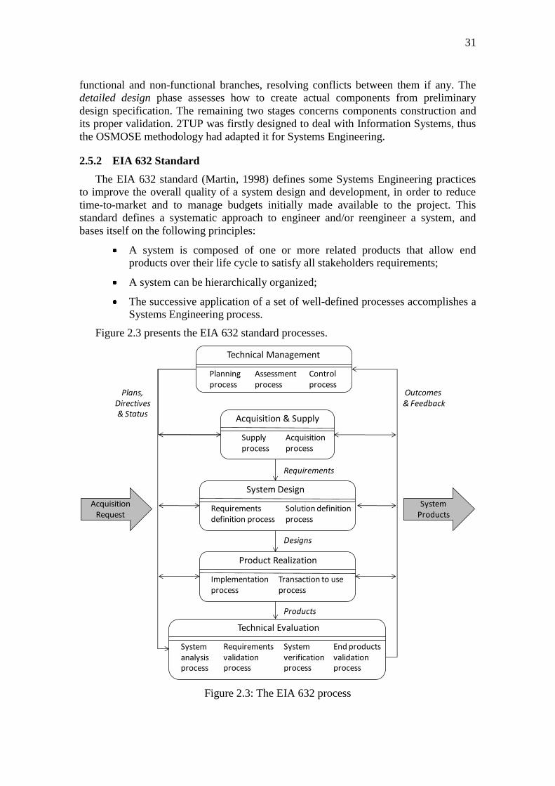
2.5.2 EIA 632 Standard
The EIA 632 standard (Martin, 1998) defines some Systems Engineering practices
to improve the overall quality of a system design and development, in order to reduce
time-to-market and to manage budgets initially made available to the project. This
standard defines a systematic approach to engineer and/or reengineer a system, and
bases itself on the following principles:
A system is composed of one or more related products that allow end
products over their life cycle to satisfy all stakeholders requirements;
A system can be hierarchically organized;
The successive application of a set of well-defined processes accomplishes a
Systems Engineering process.
Figure 2.3 presents the EIA 632 standard processes.
Technical Management
Planningprocess
Assessmentprocess
Controlprocess
Technical Evaluation
Systemanalysisprocess
Requirementsvalidationprocess
Systemverificationprocess
End productsvalidationprocess
Acquisition & Supply
Supplyprocess
Acquisitionprocess
System Design
Requirementsdefinition process
Solution definitionprocess
Product Realization
Implementationprocess
Transaction to useprocess
Requirements
Designs
Products
Plans,Directives& Status
Outcomes & Feedback
Acquisition Request
System Products
Figure 2.3: The EIA 632 process
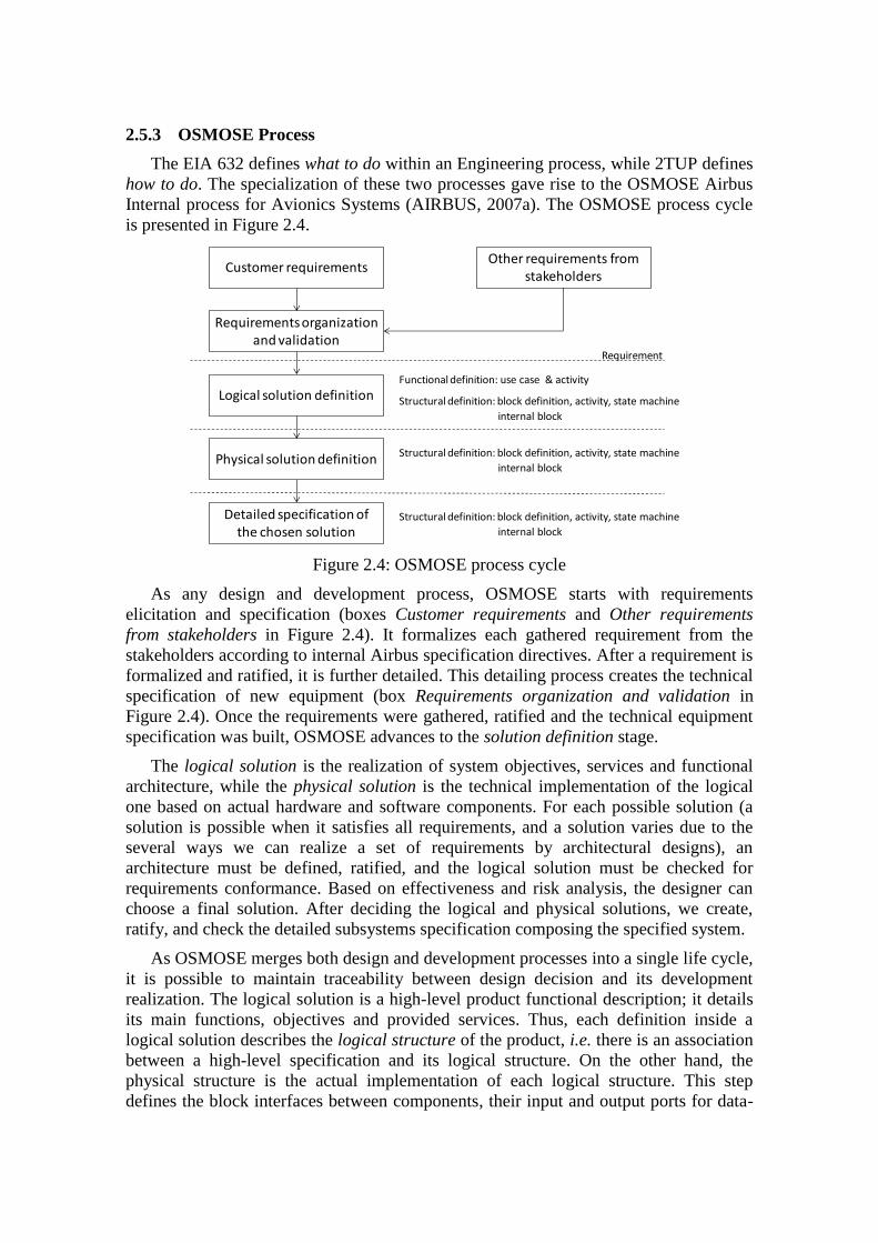
2.5.3 OSMOSE Process
The EIA 632 defines what to do within an Engineering process, while 2TUP defines
how to do. The specialization of these two processes gave rise to the OSMOSE Airbus
Internal process for Avionics Systems (AIRBUS, 2007a). The OSMOSE process cycle
is presented in Figure 2.4.
Customer requirements
Requirements organization and validation
Logical solution definition
Physical solution definition
Detailed specification of the chosen solution
Other requirements from stakeholders
Requirement
Functional definition: use case & activity
Structural definition: block definition, activity, state machine
internal block
Structural definition: block definition, activity, state machine
internal block
Structural definition: block definition, activity, state machine
internal block
Figure 2.4: OSMOSE process cycle
As any design and development process, OSMOSE starts with requirements
elicitation and specification (boxes Customer requirements and Other requirements
from stakeholders in Figure 2.4). It formalizes each gathered requirement from the
stakeholders according to internal Airbus specification directives. After a requirement is
formalized and ratified, it is further detailed. This detailing process creates the technical
specification of new equipment (box Requirements organization and validation in
Figure 2.4). Once the requirements were gathered, ratified and the technical equipment
specification was built, OSMOSE advances to the solution definition stage.
The logical solution is the realization of system objectives, services and functional
architecture, while the physical solution is the technical implementation of the logical
one based on actual hardware and software components. For each possible solution (a
solution is possible when it satisfies all requirements, and a solution varies due to the
several ways we can realize a set of requirements by architectural designs), an
architecture must be defined, ratified, and the logical solution must be checked for
requirements conformance. Based on effectiveness and risk analysis, the designer can
choose a final solution. After deciding the logical and physical solutions, we create,
ratify, and check the detailed subsystems specification composing the specified system.
As OSMOSE merges both design and development processes into a single life cycle,
it is possible to maintain traceability between design decision and its development
realization. The logical solution is a high-level product functional description; it details
its main functions, objectives and provided services. Thus, each definition inside a
logical solution describes the logical structure of the product, i.e. there is an association
between a high-level specification and its logical structure. On the other hand, the
physical structure is the actual implementation of each logical structure. This step
defines the block interfaces between components, their input and output ports for data-
33
flow and signals, creating in this way an association between the logical structure and
its physical constituting blocks.
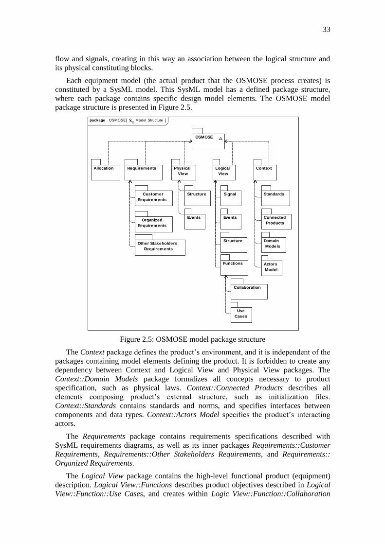
Each equipment model (the actual product that the OSMOSE process creates) is
constituted by a SysML model. This SysML model has a defined package structure,
where each package contains specific design model elements. The OSMOSE model
package structure is presented in Figure 2.5.
Model Structurepackage OSMOSE[ ]
Other Stakeholders
Requirements
Organized
Requirements
Customer
Requirements
Requirements
Collaboration
OSMOSE
Connected
Products
Standards
Allocation
Functions
Structure
Structure
Domain
Models
Physical
View
ContextLogical
View
Events
Actors
Model
Use
Cases
Events
Signal
Figure 2.5: OSMOSE model package structure
The Context package defines the product’s environment, and it is independent of the
packages containing model elements defining the product. It is forbidden to create any
dependency between Context and Logical View and Physical View packages. The
Context::Domain Models package formalizes all concepts necessary to product
specification, such as physical laws. Context::Connected Products describes all
elements composing product’s external structure, such as initialization files.
Context::Standards contains standards and norms, and specifies interfaces between
components and data types. Context::Actors Model specifies the product’s interacting
actors.
The Requirements package contains requirements specifications described with
SysML requirements diagrams, as well as its inner packages Requirements::Customer
Requirements, Requirements::Other Stakeholders Requirements, and Requirements::
Organized Requirements.
The Logical View package contains the high-level functional product (equipment)
description. Logical View::Functions describes product objectives described in Logical
View::Function::Use Cases, and creates within Logic View::Function::Collaboration

the association between these objectives and product structure. Logic View::Structure
describes product’s architecture, containing mainly block elements from SysML and
composition relationships between these blocks. It is worth noting that Logic View is
both structural and behavioral system specification.
The Physical View package specifies the actual hardware and software product
structure. Physical View::Structure realizes (or implements) the elements from Logic
View packages. Physical View also describes ports and internal connections between
actual blocks.
The Allocation package specifies the allocation of roles defined in Logical
View::Structure into Physical View::Structure actual elements.
35
3 MODELING AND SIMULATION
This chapter discusses modeling and simulation (M&S) requirements, development,
and deployment in organizations, particularly in AIRBUS. Section 3.1 introduces M&S,
and how these activities are inserted in the development cycle. Section 3.2 presents
Verification and Validation (V&V) of M&S, its basic concepts and some approaches to
perform V&V applied to M&S. Section 3.2 discusses accreditation and certification,
and how they connect with M&S for safe-critical domains. Section 3.4 presents the
NASA standard processes for M&S, which contains the basic requirements for any safe-
critical M&S activity. Finally, section 3.5 presents the AIRBUS simulation platforms,
and the Systems Engineering process deployed in AIRBUS for M&S development.
3.1 Introduction to Modeling and Simulation
With the increasingly complexity of current systems, and we include here aircrafts,
it is imperative to devise techniques to handle in an abstract and as formal as possible
fashion this complexity. Another issue is the pressure to reduce time-to-market, what
can be crucial to a new product. Just to remember the A380 delay, a €13 billion
program, and its €6.3 to €7.9 billion cash shortfall due to its two years delivery delay,
and the new prospects says that EADS is going to achieve investment break-even only
in ten years (Clark, 2006). Therefore, in addition to handle safe-critical issues, a feasible
development approach must help in respecting time development constraints and
budgets. The ACARE Quality & Affordability Report discusses that, by 2020, is
imperative to reduce 50% of current time in the supply-chain for aircraft production,
considering both time-to-market (engineering and design time of a new aircraft) and
time-to-delivery (manufacturing and delivery time to airlines), and one way of doing so
is to improve Systems Engineering processes, mainly modeling and simulation (M&S)
of new avionics equipment (ACARE, 2002).
The central concept in modeling is model. A model is a representation of something
in the real world, called model domain. Brade (2003) defines a model as:
“A model is an abstract and idealized replication of a real system,
which reflects all of its relevant properties with sufficient accuracy
with respect to the intended purpose”
It is possible to create a model even if the real system is still incomplete. A model
usually abstracts away low-level details that are useless to the analysis we are going to
conduce with the modeled system. Thus, a model can be more tractable because it is
simpler, in the opposite of the very detailed real system. We can define model
resolution as the perceived level of reality contained in the model. A model with high
resolution is closer to the real system, while a model with less resolution is more
abstract (Brade, 2003). One of the main difficulties in modeling is to define the best
suitable resolution to adopt. There is no correct answer to that; adopted resolution
barely depends on the system itself, it depends more on analysis and studies we will
carry with the model. Different analyses (or model goals) define different model views,
being each defined view more appropriate to one analysis and group of stakeholders as
the other.
A model may contain structural and behavioral descriptions. A structural
description consists of all model elements and their interdependencies and hierarchies.
The behavioral description is a functional specification of how model inputs transform
into model outputs, and how internal states of model elements change over time to
realize the generation of outputs from inputs (Brade, 2003).
A model has three representations, depending on its purposes: conceptual, formal,
and executable. A conceptual model presents the domain elements and their structure
and behavior, and centers itself in reasoning about the modeled system. A formal model
is a formal specification of the conceptual model, based on some adopted formalism
with well-defined semantics. The executable model implements the formal model, and
includes necessary information to be executed in a computer (Brade, 2003).
With a formal model, we can perform analysis of the produced outputs for the
models inputs. When we execute the model to analyze its output, we are performing a
model simulation. IEEE (2001) standard defines simulation as:
“Simulation is the execution of a model that behaves similar to the
real system when provided a set of controlled inputs over time”
The model behavior is the way outputs change over time during simulation. Brade
(2003) presents a simulation model taxonomy:
Quasi-continuous vs. discrete simulation: depending whether the state
space is continuous or discrete, respectively.
Time-stepped vs. discrete-event simulation: depending whether the
simulation advances over a predefined time intervals, or based on
triggered events in the simulation model. Time-stepped simulation
supports for real-time and in-the-loop simulations, while in discrete-event
usually external agents can trigger events conducing the simulation.
Deterministic vs. stochastic simulation: depending whether the produced
outputs depends on the inputs or not, respectively.
For more details in modeling and simulation, please refer to Brade (2003).
3.2 Verification and Validation of Simulation Models
Verification and Validation (V&V) techniques want to answer whether a model is
correct, and what we can do to ensure a model is correct. Verification aims at ensuring
that both conceptual model and its executable model are correct given the requirements
specification. Validation informs whether an executable model results are within an
acceptable range as defined in its conceptual model. V&V quite relates to model
accreditation, which is concerned with building into users the confidence necessary to
rely on the model, and on data it produces (Sargent, 2008). We will discuss model
accreditation in the next section.
37
Sargent (2008) points out four approaches to conduct model V&V inside the
simulation model development team:
The model development team is itself in charge of performing V&V
activities. The team makes subjective decisions based on earlier model
evaluations, e.g. tests or model execution;
Assuming that we have two separate teams, one dedicated to model
development, and the other to model V&V, and if the development team is
not too large, one of its members can help the conduction of V&V. In
addition to verification, this approach increases accreditation, due to the
participation of a simulation model user in its V&V process;
The approach called Independent V&V assumes a V&V authority in charge
of the decision whether V&V results proposed by the simulation model
V&V team is valid or not. This approach is suitable when the simulation
model development team is too large, or when it is involved in many projects
with several suppliers. In this approach, an iterative refinement process
between the Independent V&V authority, V&V team, and development
teams occurs;
The last approach is to use a scoring model. Scoring is conducted
subjectively, based on V&V team experience. In this case, some model
aspects are explicitly chosen over others, attributing a bigger score to the
most important, and a smaller one to the least important.
Furthermore, Sargent (2008) describes several techniques to perform V&V in
simulation models:
Animation: model’s behavior is presented in a step-by-step fashion, usually
enabling to control what is being displayed, and how animation advances;
Comparison: this technique compares the results produced by the
undergoing simulation model with a similar, previously validated, simulation
model. Based on an acceptance threshold, we can say that differences
between the two models are acceptable or not;
Degenerate tests: this tests how model degenerates when its inputs are
increasingly closer to the acceptable specified limits;
Event validity: compares the fidelity of simulated events or the number of
model elements occurrences with real ones;
Extreme condition tests: tests the robustness of the simulation model, and
how it behaves in extreme values, for example, division by zero;
Face validity: evaluates with a domain expert if the outputs the simulation
model produces are correct, or at least seems to be correct;
Historical data validation: uses previous validated data, if existing, to
validate if new produced data is correct;
Historical methods: divided into three sub-techniques: rationalism assumes
that model team knows which output is correct, and uses this knowledge to
assess the model; empiricism requires that all rational assumption to be
empirically validated; and positive economics assess causal relationships
constructed from rationalism are empirically valid;
Internal validity: only applies to stochastic models (models where outputs
are independent of inputs), assess the amount of variability produced
between model executions. Depending on the model domain, high variability
can indicate lack of consistency;
Operation graphics: V&V model team observe model behavior with
graphical analysis of its generated output;
Sensitivity analysis: variations in model outputs caused by perturbations in
its inputs must be the same in both the real system and the simulation model;
Predictive validation: V&V team uses the model to foresee the real system
behavior. Usually, this model is developed before the real system, in order to
conduct feasibility analysis, for example;
Traces: several modeled entities have their execution traced to check if they
behave properly and as expected during simulation execution;
Turing tests: experts in the model domain evaluate if they can discriminate
the outputs produced between simulation and real systems.
3.3 Model Simulation Accreditation and Certification
When we refer to accreditation and certification, we mean that the product under
certification provides guarantees that it supports all requirements agreed by parts as
being important for product’s domain. Certification is necessary because, while we still
continue not to use exhaustive V&V techniques (mainly due to scalability issues), we
cannot be sure that our models are 100% reliable, correct, and suitable (Brade, 2003).
Assuming this, we need to define the degree of confidence a model provides. This
degree is based both on model’s depth (it implements the correct level of details of its
functionalities) and breadth (it implements all functionalities it needs to provide).
Model suitability is a measure that accounts if model’s depth and breadth are acceptable
to model requirements. Based on these concepts, Brade (2003) defines credibility:
“The credibility of a model or simulation results is an expression of
the degree to which one is convinced that a particular model or
particular set of simulations results are suitable for an intended
purpose and correct”
Accreditation is the process of certification that a legal and recognized Institution or
Body conducts to assert if the product (in our case simulation models) has credibility for
its purpose. Balci (2001), based on the International Standardization Office (ISO),
presents the definition of certification and accreditation as:
“Certification is a procedure by which a third party gives written
assurance that a product, process or service conforms to specified
characteristics”
“Accreditation is a procedure by which an authoritative body gives
formal recognition that a body or person is competent to carry out
specific tasks”
39
The US Department of Defense (DoD-US) defines simulation model accreditation as
(Brade, 2003 apud DoD-US 1996).
“Accreditation is the official certification that a model, simulation,
or federation of models and simulations is acceptable for use for a
specific purpose”
In AIRBUS, simulation is not certified yet, but with the steps beyond integrating
design and simulation, in the future certifying executable simulation models may be
interesting. If executable simulation models were certified, design teams and external
suppliers could reuse them, reducing time-to-market and increasing credibility in the
aircraft development cycle and its iterations. Considering the aeronautical domain as a
multidomain and safe-critical, where knowledge from several disciples interconnect,
certification is still complicated, being a difficult process and management issue if
deciding to certify simulation models (Rodríguez-Dapena, 1999).
3.4 Modeling and Simulation Standard: NASA Approach
The three most deployed standards for M&S were proposed by three governmental
agencies: the US Department of Defense (DoD-US, 2004), the Australian Department
of Defence (DoD-AU, 2005), and the National Aeronautical and Space Administration
(NASA, 2008). We do not see published proposals from industry to M&S, and usually
companies adapt one of the three presented M&S standards (as is the case in Boeing
Company, which adapts the DoD-US approach). To present the requirements involved
in M&S activities, this section describes requirements from the NASA M&S standard
(NASA, 2008), and as all the three standards are similar, we have a good coverage of
existing requirements to develop M&S activities. NASA created this standard to tackle
the following activities, which can be adopted and adapted in any organization:
Identify best practices to ensure that knowledge from operations is captured
in the user interfaces (the way users interact with models);
Develop process for tool verification, validation, certification, reverification,
revalidation, and recertification based on operational data;
Develop standards for documentation, configuration management, and
quality assurance;
Identify any training or certification requirements to ensure proper
operational capabilities;
Provide a plan for tool management, maintenance, and obsolescence
consistent with M&S environments;
Develop a process for user feedback when results appear unrealistic or defy
explanations;
Provide a standard method to assess the credibility of the models and
simulations presented to stakeholders when making critical decisions;
Assure that model and simulation credibility meets project requirements.
The organization or group of individuals in charge of conducting M&S is called
responsible party. The responsible party is in charge of M&S activities inside the
project or program, and is responsible of requirements analysis, documents
management, and the definition of objectives for all M&S activities. In the following,
we present the requirements associated with each M&S activity defined in the NASA
M&S standard the responsible party must perform. Note that these requirements can be
adapted for each specific M&S project or program; it is not necessary to conduct all
existing requirements.
Concerning M&S program management, NASA (2004) defines for the responsible
party:
Define M&S acceptance criteria and accreditation;
Define scoring rationale to V&V activities;
Define the intended use of M&S;
Define metrics to assess program milestones;
Report M&S results to support technical decisions;
Control management of M&S (artifacts, project schedule, and processes).
Concerning model development, responsible party’s activities are:
Document design decisions in the conceptual model;
Document model structure and behavior (e.g. equations);
Document model inputs and data set to be used;
Document units of the input data;
Document model’s limits of operation;
Document how to use correctly the model;
Document how to calibrate input data;
Document model update, assigning for each different update an unique
identification;
Document criteria and date for model obsolescence;
Provide a mechanism to enable model users to report erroneous behavior and
non expected results found with the model;
Keep models and associated documentation in control management
repository.
Concerning model simulation and analysis, activities are:
Assure that simulations occurred within the established limits, or, in case of
transposing these limits, document the consequences in doing so;
Document warning and error messages found during simulation;
Document the version of M&S analysis results;
Document necessary computational resources to execute the simulation;
Document the process of constructing and publishing acquired simulation
results to stakeholders;
41
Document the history of M&S within the same or close applications that are
useful to establish model credibility for the current M&S application;
Document the evaluation if performed simulation and analysis are useful to
the current M&S application;
Document any decision concerning simulation and analysis configuration.
Concerning model V&V, activities are:
Document which V&V techniques were used;
Document numerical estimation errors, convergence, precision for the
results;
Document current status of model V&V;
Document metrics used to validate the model and its inputs;
Document any studies conducted with the simulation results.
Finally, concerning model credibility, activities are:
Identify model credibility based on criteria established for the project;
Justify assigned credibility for all used criteria;
Sum up scores and assign overall model credibility score;
Publish results to stakeholders;
Include warnings in the final report when: some acceptance criteria was not
met, violation of any model’s premises, violation in model operational limits,
execution errors and warning messages thrown, unfavorable results from the
analysis of simulation results.
3.5 Model Simulation at AIRBUS
3.5.1 System Simulators
Simulation has three branches at AIRBUS: engineering, which is used to test and to
validate aircraft equipments during the development of aircraft systems, and is very
useful to test flight parameters on ground in order to guide equipments design: training,
which is used to train aircraft crew, in this case AIRBUS delivers to Full Flight
simulators manufacturers the core simulation systems; and research, which is
independent of an aircraft program and is used to carry tests on new concepts and
designs, and architectural proposals. In general, system simulation is very important to
reduce development time.
Inside AIRBUS, there is the Simulation Products Department (EDYYS), which is in
charge of functional simulation activities, being the AIRBUS centre of competence on
real-time simulation. The EDYYS has expertise on aircraft system simulation and is
deeply involved on the aircraft development process. It has expertise also on
electronics, flight simulation methods and architectures. Its main missions are: to
design, develop and integrate simulation hardware and software components into
simulators, as well as to assure their maintenance within the Company; to design
electronic interfaces for engineering simulators; to develop software simulation
packages for every new aircraft program started; to guarantee that training simulators
will be available before the new aircraft entries into service; to facilitate the
development of low cost and high quality training devices; and to develop commercial
business simulators together with the airlines and with training centers.
Figure 3.1 jointly presents the AIRBUS aircraft development and simulation cycles.
The simulation and development cycles at AIRBUS take the form of a standard V
development cycle (Forsberg, 1991), where it is possible to note that a simulation
platform (white boxes) is associated for every development phase (gray boxes). In this
way, simulation is highly coupled with the development, enhancing quality for the later
development phases quite early in the development cycle.
The following simulators compose the simulation platform at AIRBUS:
EPOPÉE (Etude Prospective pour l’Organisation d’un Poste d’Equipage
Ergonomique): this simulator corresponds to the first simulation platform of
Figure 3.1. It helps the development teams to choose new design concepts
and techniques before a new aircraft program is launched, assessing control
laws, cockpit ergonomics and crew workload;
OCASIME (Outil de Conception Assistée de Simulation Multi-
Equipements) : this simulator is dedicated to system design, hosting software
simulating the flight loop and other programs used to validate and test
aircraft logics and equipments specification;
A/C -1: this simulator is specific for a given aircraft program, and provides a
representative system simulation used to test and to improve control laws, to
assess cockpit ergonomics and crew workload. It represents most of the
elements on the cockpit and some buttons are operational through touch
screens.
System Integration Test Rigs: after complete equipment definition and
development, we integrate single equipment on functional test rigs connected
to simulation platforms. These platforms host simulation packages
simulating some aircraft systems such as the Flight Warning System (checks
the aircraft integrity) and the Control and Display System (displays the
cockpit information).
A/C 0: this simulator, also called Iron Bird, integrates all actual equipments
before their deployment on the final aircraft. It needs the most representative
environments, and is composed of a real cockpit, all on-board computers, a
reproduction of electrical and hydraulics wiring, aircraft actuators, and
environment system simulation (simulates real world atmosphere conditions,
such as rain, snow, hot, and so on), and aircraft physics (flight mechanics).
3.5.2 Development, Integration and Validation of Simulation Models
The current AIRBUS process for developing, integrating, and validating simulation
models is the AP2633 (AIRBUS, 2008). When we say simulation model, actually we
refer to an AP2633 Compliant Simulation Model. Thus, a simulation model must
comply with AP2663 process directives to be deployable in the system simulators
presented in the last section. The AP2633 process is a standard V cycle, and is divided
in four phases: definition, development, evolution, and maintenance.
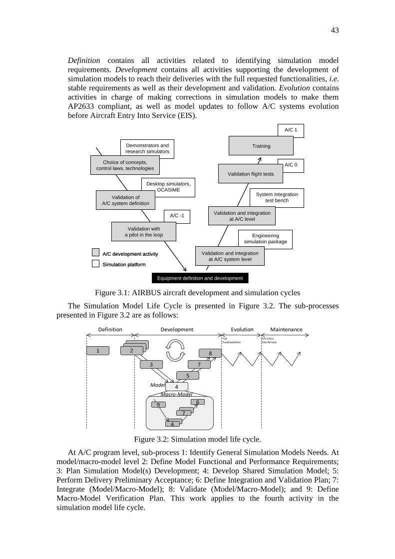
43
Definition contains all activities related to identifying simulation model
requirements. Development contains all activities supporting the development of
simulation models to reach their deliveries with the full requested functionalities, i.e.
stable requirements as well as their development and validation. Evolution contains
activities in charge of making corrections in simulation models to make them
AP2633 compliant, as well as model updates to follow A/C systems evolution
before Aircraft Entry Into Service (EIS).
Figure 3.1: AIRBUS aircraft development and simulation cycles
The Simulation Model Life Cycle is presented in Figure 3.2. The sub-processes
presented in Figure 3.2 are as follows:
Definition
1 2
4
8
Development
Model
4
6
Evolution Maintenance
9
7
Macro-Model
3
5
7
Full Functionalities
A/C EntryInto Service
Figure 3.2: Simulation model life cycle.
At A/C program level, sub-process 1: Identify General Simulation Models Needs. At
model/macro-model level 2: Define Model Functional and Performance Requirements;
3: Plan Simulation Model(s) Development; 4: Develop Shared Simulation Model; 5:
Perform Delivery Preliminary Acceptance; 6: Define Integration and Validation Plan; 7:
Integrate (Model/Macro-Model); 8: Validate (Model/Macro-Model); and 9: Define
Macro-Model Verification Plan. This work applies to the fourth activity in the
simulation model life cycle.
Engineering
simulation package
System Integration
test bench
A/C 0
A/C 1
A/C -1
Desktop simulators,
OCASIME
Demonstrators and
research simulators
Choice of concepts,
control laws, technologies
Validation of
A/C system definition
Validation with
a pilot in the loop
Equipment definition and development
Validation and integration
at A/C system level
Validation and integration
at A/C level
Validation flight tests
Training
A/C development activity
Simulation platform
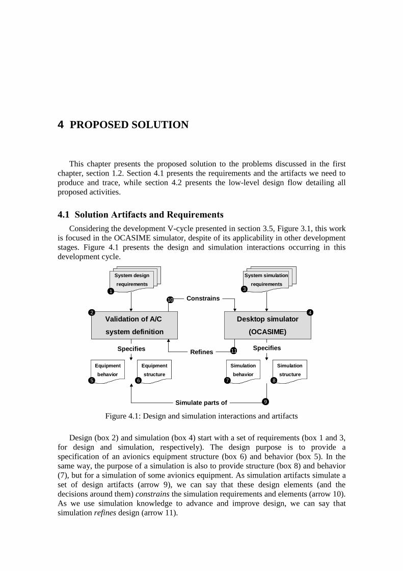
4 PROPOSED SOLUTION
This chapter presents the proposed solution to the problems discussed in the first
chapter, section 1.2. Section 4.1 presents the requirements and the artifacts we need to
produce and trace, while section 4.2 presents the low-level design flow detailing all
proposed activities.
4.1 Solution Artifacts and Requirements
Considering the development V-cycle presented in section 3.5, Figure 3.1, this work
is focused in the OCASIME simulator, despite of its applicability in other development
stages. Figure 4.1 presents the design and simulation interactions occurring in this
development cycle.
Design (box 2) and simulation (box 4) start with a set of requirements (box 1 and 3,
for design and simulation, respectively). The design purpose is to provide a
specification of an avionics equipment structure (box 6) and behavior (box 5). In the
same way, the purpose of a simulation is also to provide structure (box 8) and behavior
(7), but for a simulation of some avionics equipment. As simulation artifacts simulate a
set of design artifacts (arrow 9), we can say that these design elements (and the
decisions around them) constrains the simulation requirements and elements (arrow 10).
As we use simulation knowledge to advance and improve design, we can say that
simulation refines design (arrow 11).
Desktop simulator
(OCASIME)
Validation of A/C
system definition
System design
requirements
System simulation
requirements
Equipment
behavior
Equipment
structure
Simulation
behavior
Simulation
structure
Simulate parts of
Specifies SpecifiesRefines
Constrains1
2
3
4
5 6 7 8
9
10
11
Desktop simulator
(OCASIME)
Validation of A/C
system definition
System design
requirements
System simulation
requirements
Equipment
behavior
Equipment
structure
Simulation
behavior
Simulation
structure
Simulate parts of
Specifies SpecifiesRefines
Constrains1
2
3
4
5 6 7 8
9
10
11
Figure 4.1: Design and simulation interactions and artifacts
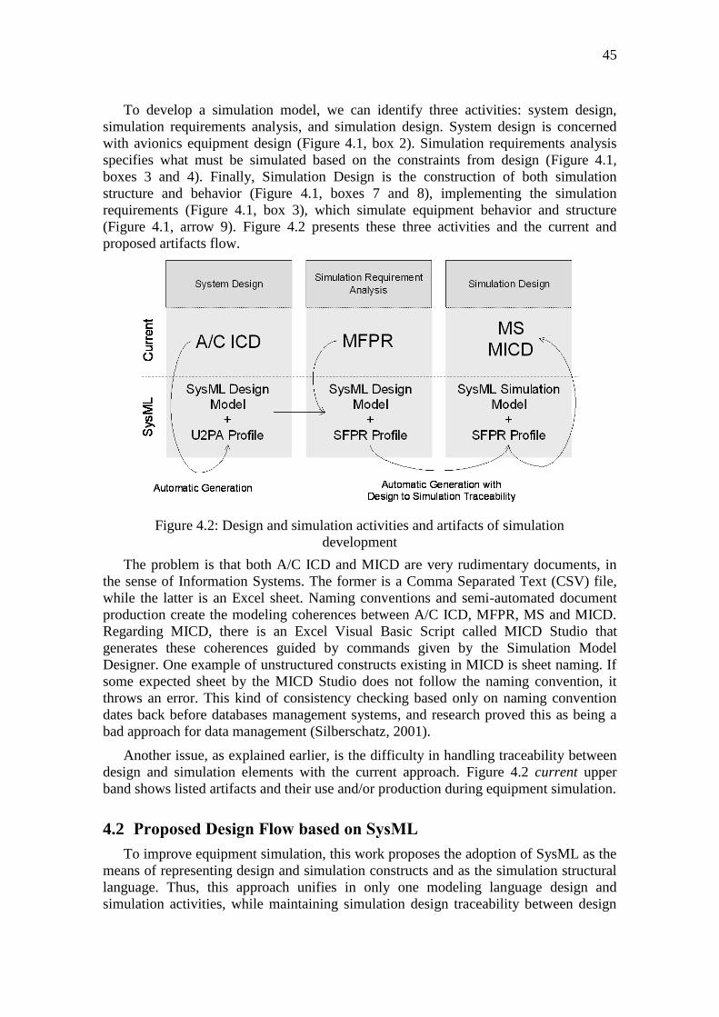
45
To develop a simulation model, we can identify three activities: system design,
simulation requirements analysis, and simulation design. System design is concerned
with avionics equipment design (Figure 4.1, box 2). Simulation requirements analysis
specifies what must be simulated based on the constraints from design (Figure 4.1,
boxes 3 and 4). Finally, Simulation Design is the construction of both simulation
structure and behavior (Figure 4.1, boxes 7 and 8), implementing the simulation
requirements (Figure 4.1, box 3), which simulate equipment behavior and structure
(Figure 4.1, arrow 9). Figure 4.2 presents these three activities and the current and
proposed artifacts flow.
The problem is that both A/C ICD and MICD are very rudimentary documents, in
the sense of Information Systems. The former is a Comma Separated Text (CSV) file,
while the latter is an Excel sheet. Naming conventions and semi-automated document
production create the modeling coherences between A/C ICD, MFPR, MS and MICD.
Regarding MICD, there is an Excel Visual Basic Script called MICD Studio that
generates these coherences guided by commands given by the Simulation Model
Designer. One example of unstructured constructs existing in MICD is sheet naming. If
some expected sheet by the MICD Studio does not follow the naming convention, it
throws an error. This kind of consistency checking based only on naming convention
dates back before databases management systems, and research proved this as being a
bad approach for data management (Silberschatz, 2001).
Another issue, as explained earlier, is the difficulty in handling traceability between
design and simulation elements with the current approach. Figure 4.2 current upper
band shows listed artifacts and their use and/or production during equipment simulation.
4.2 Proposed Design Flow based on SysML
To improve equipment simulation, this work proposes the adoption of SysML as the
means of representing design and simulation constructs and as the simulation structural
language. Thus, this approach unifies in only one modeling language design and
simulation activities, while maintaining simulation design traceability between design
Figure 4.2: Design and simulation activities and artifacts of simulation
development
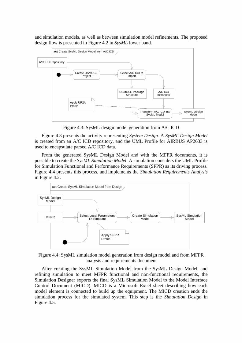
and simulation models, as well as between simulation model refinements. The proposed
design flow is presented in Figure 4.2 in SysML lower band.
act Create SysML Design Model from A/C ICD
A/C ICD Repository
Create OSMOSEProject
Select A/C ICD toImport
OSMOSE PackageStructure
A/C ICDInstances
Transform A/C ICD intoSysML Model
SysML DesignModel
Apply UP2A
Profile
Figure 4.3: SysML design model generation from A/C ICD
Figure 4.3 presents the activity representing System Design. A SysML Design Model
is created from an A/C ICD repository, and the UML Profile for AIRBUS AP2633 is
used to encapsulate parsed A/C ICD data.
From the generated SysML Design Model and with the MFPR documents, it is
possible to create the SysML Simulation Model. A simulation considers the UML Profile
for Simulation Functional and Performance Requirements (SFPR) as its driving process.
Figure 4.4 presents this process, and implements the Simulation Requirements Analysis
in Figure 4.2.
act Create SysML Simulation Model from Design
SysML DesignModel
MFPRSelect Local Parameters
To SimulateCreate Simulation
ModelSysML Simulation
Model
Apply SFPR
Profile
Figure 4.4: SysML simulation model generation from design model and from MFPR
analysis and requirements document
After creating the SysML Simulation Model from the SysML Design Model, and
refining simulation to meet MFPR functional and non-functional requirements, the
Simulation Designer exports the final SysML Simulation Model to the Model Interface
Control Document (MICD). MICD is a Microsoft Excel sheet describing how each
model element is connected to build up the equipment. The MICD creation ends the
simulation process for the simulated system. This step is the Simulation Design in
Figure 4.5.
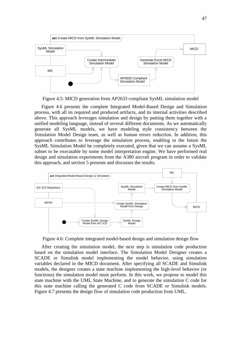
47
act Create MICD from SysML Simulation Model
SysML SimulationModel
MS
MICD
Create Intermediate Simulation Model
Generate Excel MICDSimulation Model
AP2633 CompliantSimulation Model
Figure 4.5: MICD generation from AP2633 compliant SysML simulation model
Figure 4.6 presents the complete Integrated Model-Based Design and Simulation
process, with all its required and produced artifacts, and its internal activities described
above. This approach leverages simulation and design by putting them together with a
unified modeling language, instead of several different documents. As we automatically
generate all SysML models, we have modeling style consistency between the
Simulation Model Design team, as well as human errors reduction. In addition, this
approach contributes to leverage the simulation process, enabling in the future the
SysML Simulation Model be completely executed, given that we can assume a SysML
subset to be executable by some model interpretation engine. We have performed real
design and simulation experiments from the A380 aircraft program in order to validate
this approach, and section 5 presents and discusses the results.
act Integrated Model-Based Design & Simulation
A/C ICD Repository
MFPR
Create SysML DesignModel from A/C ICD
Create SysML SimulationModel from Design
SysML DesignModel
SysML SimulationModel
MS
Create MICD from SysML Simulation Model
MICD
Figure 4.6: Complete integrated model-based design and simulation design flow
After creating the simulation model, the next step is simulation code production
based on the simulation model interface. The Simulation Model Designer creates a
SCADE or Simulink model implementing the model behavior, using simulation
variables declared in the MICD document. After specifying all SCADE and Simulink
models, the designer creates a state machine implementing the high-level behavior (or
functions) the simulation model must perform. In this work, we propose to model this
state machine with the UML State Machine, and to generate the simulation C code for
this state machine calling the generated C code from SCADE or Simulink models.
Figure 4.7 presents the design flow of simulation code production from UML.
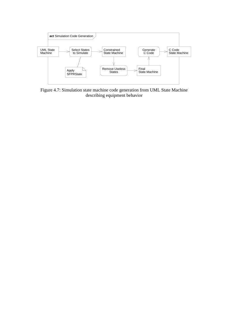
act Simulation Code Generation
UML StateMachine
Select Statesto Simulate
Apply
SFPRState
ConstrainedState Machine
Remove UselessStates
FinalState Machine
GenerateC Code
C CodeState Machine
Figure 4.7: Simulation state machine code generation from UML State Machine
describing equipment behavior
49
5 CASE STUDIES
This chapter presents the case studies we have performed to validate our proposal. It
presents the approach from its user perspective. Section 5.1 presents the A380
navigation system, and the generation of its specification to SysML Design Models, as
well as the MICD production from SysML Simulation Models. Section 5.2 presents the
Primary Flight Control Computer and the code generation process for its UML
Equipment State Machine.
5.1 A380 Navigation System
5.1.1 Navigation System Probes Embedded Avionics
The A380 navigation system, which the ATA 34 chapter regulates, is composed of
33 equipment occurrences, as follows:
Two Automatic Direction Finders (ADF) occurrences. ADF is one of the
simplest, but very useful, navigation equipment used when flying by
instruments. The ADF points a navigator (it can be an arrow or digital earth
coordinates) in the direction of a tuned radio frequency emitter;
Three Air Data Inertial Reference Unit (ADIRU) occurrences. ADIRU is
composed of two applications, Air Data Reference (ADR) and Inertial
Reference System (IRS). ADR provides air data information concerning
airspeed, angle of attack, altitude, and IRS provides the aircraft position and
attitude. These data are available to both the pilots and the aircraft;
One Air Data Switching (ADS) occurrence;
One Autotrim Heading Angle (ATT-HDG) occurrence. It enables to set
(autotrim) an aircraft inclination based on the aircraft’s nose (heading angle)
Two Distance Measuring Equipment (DME) occurrences. DME provides the
aircraft distance to the ground station. UHF waves sent from ground stations
are caught by DME, and based on the time needed to these ground stations
acknowledging the reception of waves sent back by the aircraft, DME can
calculate the aircraft distance from ground;
Two Integrated Standby Instrument System (ISIS) occurrences. ISIS displays
airspeed, altitude, Mach, attitude, and vertical speed;
Six Prise de Pression Statique (ISP) occurrences. It also calculates air data
based on wind static pressure;
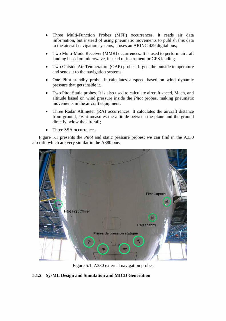
Three Multi-Function Probes (MFP) occurrences. It reads air data
information, but instead of using pneumatic movements to publish this data
to the aircraft navigation systems, it uses an ARINC 429 digital bus;
Two Multi-Mode Receiver (MMR) occurrences. It is used to perform aircraft
landing based on microwave, instead of instrument or GPS landing.
Two Outside Air Temperature (OAP) probes. It gets the outside temperature
and sends it to the navigation systems;
One Pitot standby probe. It calculates airspeed based on wind dynamic
pressure that gets inside it.
Two Pitot Static probes. It is also used to calculate aircraft speed, Mach, and
altitude based on wind pressure inside the Pitot probes, making pneumatic
movements in the aircraft equipment;
Three Radar Altimeter (RA) occurrences. It calculates the aircraft distance
from ground, i.e. it measures the altitude between the plane and the ground
directly below the aircraft;
Three SSA occurrences.
Figure 5.1 presents the Pitot and static pressure probes; we can find in the A330
aircraft, which are very similar in the A380 one.
Figure 5.1: A330 external navigation probes
5.1.2 SysML Design and Simulation and MICD Generation
Prises de pression statique
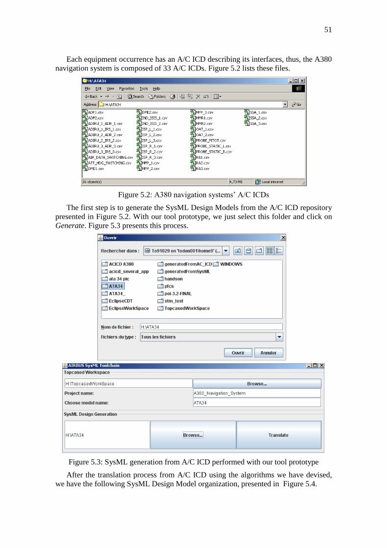
51
Each equipment occurrence has an A/C ICD describing its interfaces, thus, the A380
navigation system is composed of 33 A/C ICDs. Figure 5.2 lists these files.
Figure 5.2: A380 navigation systems’ A/C ICDs
The first step is to generate the SysML Design Models from the A/C ICD repository
presented in Figure 5.2. With our tool prototype, we just select this folder and click on
Generate. Figure 5.3 presents this process.
Figure 5.3: SysML generation from A/C ICD performed with our tool prototype
After the translation process from A/C ICD using the algorithms we have devised,
we have the following SysML Design Model organization, presented in Figure 5.4.
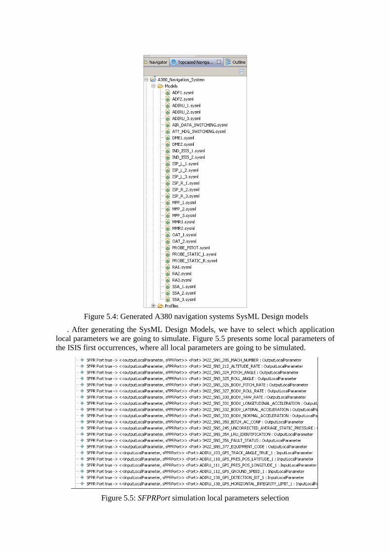
Figure 5.4: Generated A380 navigation systems SysML Design models
. After generating the SysML Design Models, we have to select which application
local parameters we are going to simulate. Figure 5.5 presents some local parameters of
the ISIS first occurrences, where all local parameters are going to be simulated.
Figure 5.5: SFPRPort simulation local parameters selection
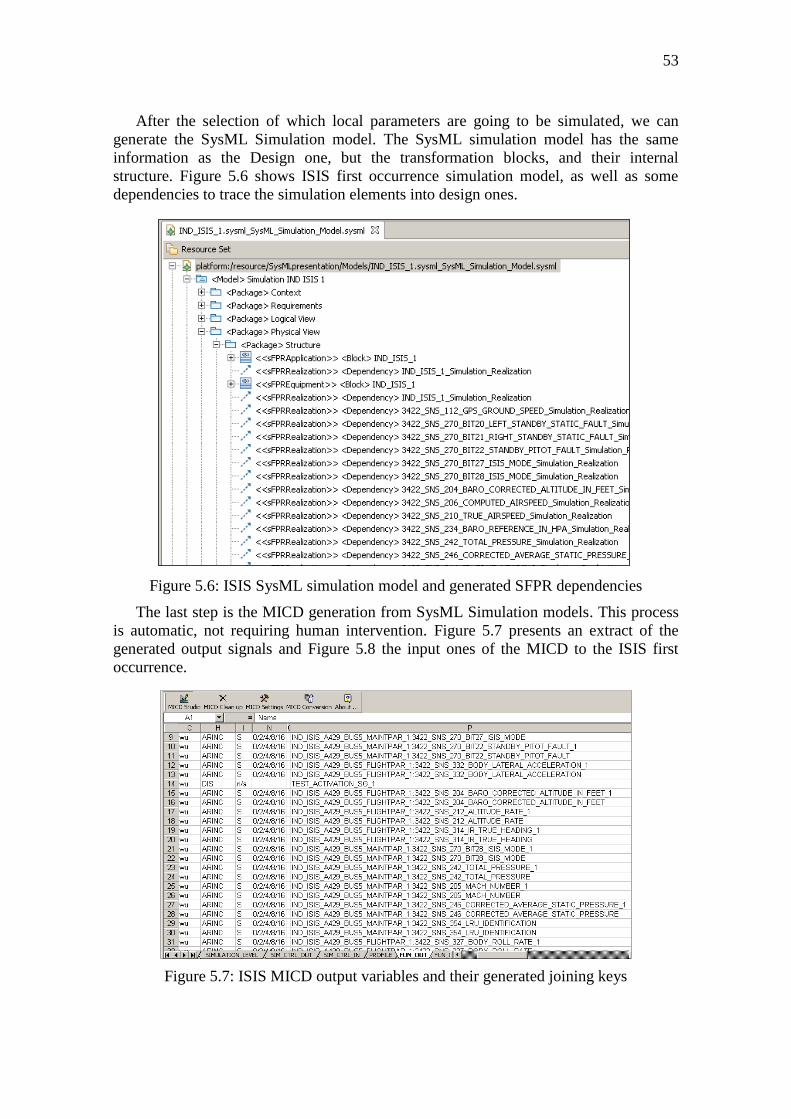
53
After the selection of which local parameters are going to be simulated, we can
generate the SysML Simulation model. The SysML simulation model has the same
information as the Design one, but the transformation blocks, and their internal
structure. Figure 5.6 shows ISIS first occurrence simulation model, as well as some
dependencies to trace the simulation elements into design ones.
Figure 5.6: ISIS SysML simulation model and generated SFPR dependencies
The last step is the MICD generation from SysML Simulation models. This process
is automatic, not requiring human intervention. Figure 5.7 presents an extract of the
generated output signals and Figure 5.8 the input ones of the MICD to the ISIS first
occurrence.
Figure 5.7: ISIS MICD output variables and their generated joining keys
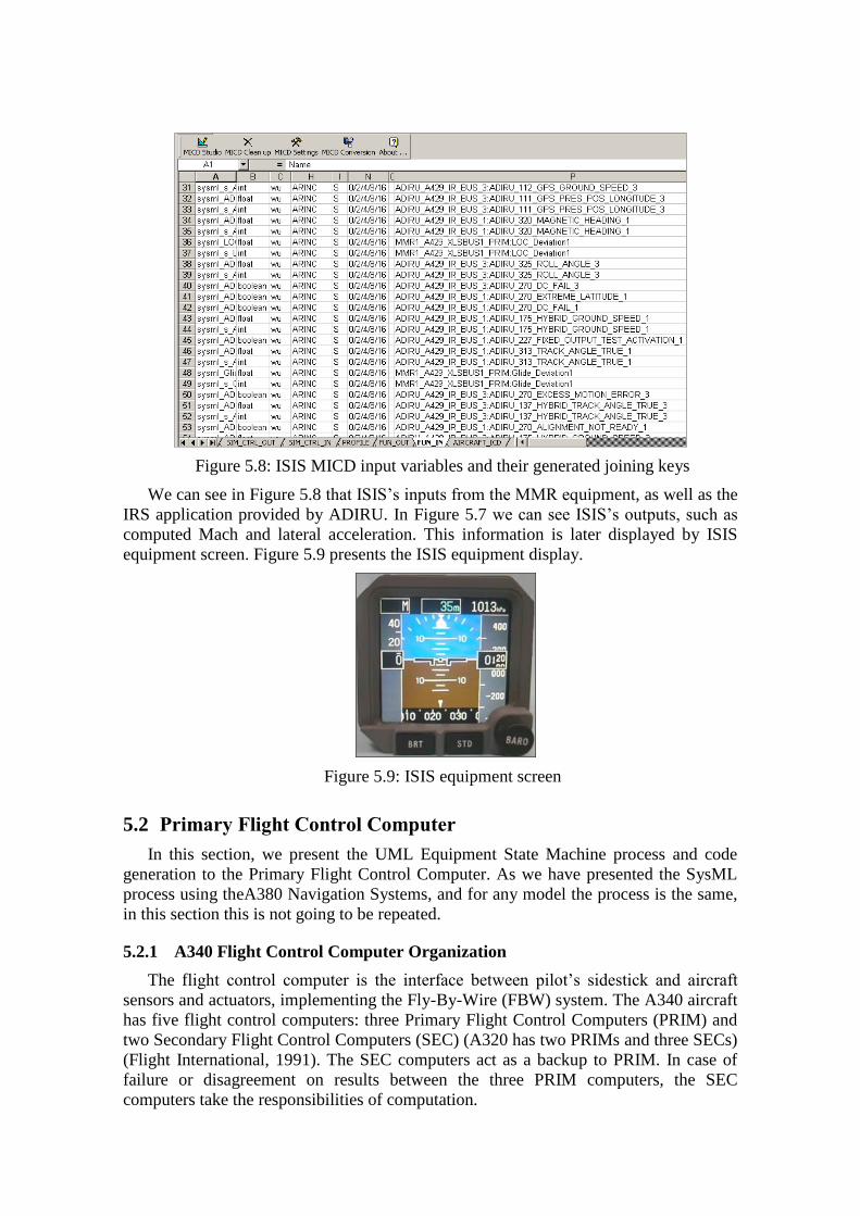
Figure 5.8: ISIS MICD input variables and their generated joining keys
We can see in Figure 5.8 that ISIS’s inputs from the MMR equipment, as well as the
IRS application provided by ADIRU. In Figure 5.7 we can see ISIS’s outputs, such as
computed Mach and lateral acceleration. This information is later displayed by ISIS
equipment screen. Figure 5.9 presents the ISIS equipment display.
Figure 5.9: ISIS equipment screen
5.2 Primary Flight Control Computer
In this section, we present the UML Equipment State Machine process and code
generation to the Primary Flight Control Computer. As we have presented the SysML
process using theA380 Navigation Systems, and for any model the process is the same,
in this section this is not going to be repeated.
5.2.1 A340 Flight Control Computer Organization
The flight control computer is the interface between pilot’s sidestick and aircraft
sensors and actuators, implementing the Fly-By-Wire (FBW) system. The A340 aircraft
has five flight control computers: three Primary Flight Control Computers (PRIM) and
two Secondary Flight Control Computers (SEC) (A320 has two PRIMs and three SECs)
(Flight International, 1991). The SEC computers act as a backup to PRIM. In case of
failure or disagreement on results between the three PRIM computers, the SEC
computers take the responsibilities of computation.
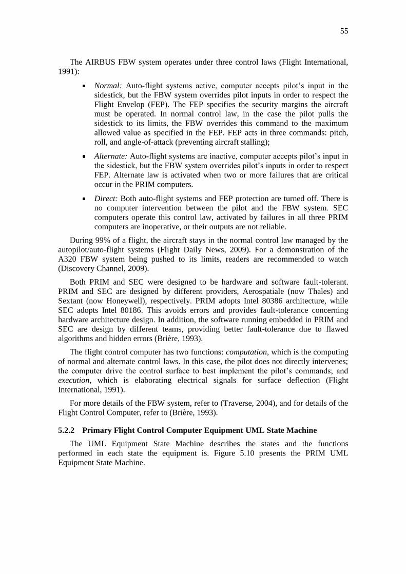
55
The AIRBUS FBW system operates under three control laws (Flight International,
1991):
Normal: Auto-flight systems active, computer accepts pilot’s input in the
sidestick, but the FBW system overrides pilot inputs in order to respect the
Flight Envelop (FEP). The FEP specifies the security margins the aircraft
must be operated. In normal control law, in the case the pilot pulls the
sidestick to its limits, the FBW overrides this command to the maximum
allowed value as specified in the FEP. FEP acts in three commands: pitch,
roll, and angle-of-attack (preventing aircraft stalling);
Alternate: Auto-flight systems are inactive, computer accepts pilot’s input in
the sidestick, but the FBW system overrides pilot’s inputs in order to respect
FEP. Alternate law is activated when two or more failures that are critical
occur in the PRIM computers.
Direct: Both auto-flight systems and FEP protection are turned off. There is
no computer intervention between the pilot and the FBW system. SEC
computers operate this control law, activated by failures in all three PRIM
computers are inoperative, or their outputs are not reliable.
During 99% of a flight, the aircraft stays in the normal control law managed by the
autopilot/auto-flight systems (Flight Daily News, 2009). For a demonstration of the
A320 FBW system being pushed to its limits, readers are recommended to watch
(Discovery Channel, 2009).
Both PRIM and SEC were designed to be hardware and software fault-tolerant.
PRIM and SEC are designed by different providers, Aerospatiale (now Thales) and
Sextant (now Honeywell), respectively. PRIM adopts Intel 80386 architecture, while
SEC adopts Intel 80186. This avoids errors and provides fault-tolerance concerning
hardware architecture design. In addition, the software running embedded in PRIM and
SEC are design by different teams, providing better fault-tolerance due to flawed
algorithms and hidden errors (Brière, 1993).
The flight control computer has two functions: computation, which is the computing
of normal and alternate control laws. In this case, the pilot does not directly intervenes;
the computer drive the control surface to best implement the pilot’s commands; and
execution, which is elaborating electrical signals for surface deflection (Flight
International, 1991).
For more details of the FBW system, refer to (Traverse, 2004), and for details of the
Flight Control Computer, refer to (Brière, 1993).
5.2.2 Primary Flight Control Computer Equipment UML State Machine
The UML Equipment State Machine describes the states and the functions
performed in each state the equipment is. Figure 5.10 presents the PRIM UML
Equipment State Machine.
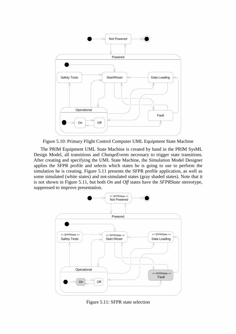
Not Powered
Powered
Data Loading
Fault
Operational
On Off
Start/ResetSafety Tests
Figure 5.10: Primary Flight Control Computer UML Equipment State Machine
The PRIM Equipment UML State Machine is created by hand in the PRIM SysML
Design Model, all transitions and ChangeEvents necessary to trigger state transitions.
After creating and specifying the UML State Machine, the Simulation Model Designer
applies the SFPR profile and selects which states he is going to use to perform the
simulation he is creating. Figure 5.11 presents the SFPR profile application, as well as
some simulated (white states) and not-simulated states (gray shaded states). Note that it
is not shown in Figure 5.11, but both On and Off states have the SFPRState stereotype,
suppressed to improve presentation.
<< SFPRState >>
Not Powered
Powered
<< SFPRState >>
Data Loading
Fault
Operational
<< SFPRState >> Start / Reset
On Off
<< SFPRState >>
<< SFPRState >>
Safety Tests
Figure 5.11: SFPR state selection
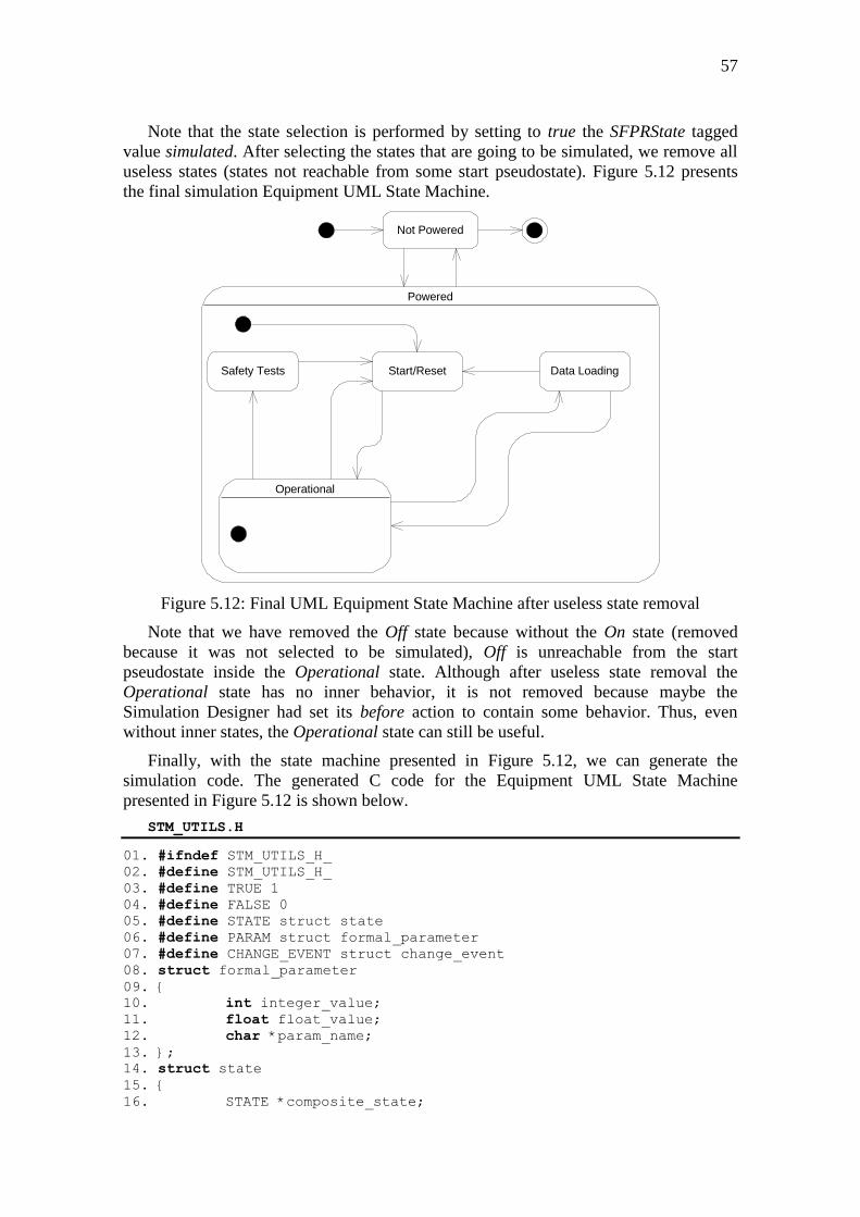
57
Note that the state selection is performed by setting to true the SFPRState tagged
value simulated. After selecting the states that are going to be simulated, we remove all
useless states (states not reachable from some start pseudostate). Figure 5.12 presents
the final simulation Equipment UML State Machine.
Not Powered
Powered
Data Loading
Operational
Start/ResetSafety Tests
Figure 5.12: Final UML Equipment State Machine after useless state removal
Note that we have removed the Off state because without the On state (removed
because it was not selected to be simulated), Off is unreachable from the start
pseudostate inside the Operational state. Although after useless state removal the
Operational state has no inner behavior, it is not removed because maybe the
Simulation Designer had set its before action to contain some behavior. Thus, even
without inner states, the Operational state can still be useful.
Finally, with the state machine presented in Figure 5.12, we can generate the
simulation code. The generated C code for the Equipment UML State Machine
presented in Figure 5.12 is shown below.
STM_UTILS.H
01. #ifndef STM_UTILS_H_
02. #define STM_UTILS_H_
03. #define TRUE 1
04. #define FALSE 0
05. #define STATE struct state
06. #define PARAM struct formal_parameter
07. #define CHANGE_EVENT struct change_event
08. struct formal_parameter
09. {
10. int integer_value;
11. float float_value;
12. char *param_name;
13. };
14. struct state
15. {
16. STATE *composite_state;
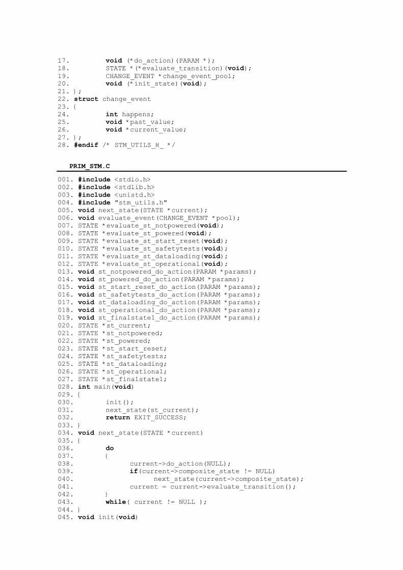
17. void (*do_action)(PARAM *);
18. STATE *(*evaluate_transition)(void);
19. CHANGE_EVENT *change_event_pool;
20. void (*init_state)(void);
21. };
22. struct change_event
23. {
24. int happens;
25. void *past_value;
26. void *current_value;
27. };
28. #endif /* STM_UTILS_H_ */
PRIM_STM.C
001. #include <stdio.h>
002. #include <stdlib.h>
003. #include <unistd.h>
004. #include "stm_utils.h"
005. void next_state(STATE *current);
006. void evaluate_event(CHANGE_EVENT *pool);
007. STATE *evaluate_st_notpowered(void);
008. STATE *evaluate_st_powered(void);
009. STATE *evaluate_st_start_reset(void);
010. STATE *evaluate_st_safetytests(void);
011. STATE *evaluate_st_dataloading(void);
012. STATE *evaluate_st_operational(void);
013. void st_notpowered_do_action(PARAM *params);
014. void st_powered_do_action(PARAM *params);
015. void st_start_reset_do_action(PARAM *params);
016. void st_safetytests_do_action(PARAM *params);
017. void st_dataloading_do_action(PARAM *params);
018. void st_operational_do_action(PARAM *params);
019. void st_finalstate1_do_action(PARAM *params);
020. STATE *st_current;
021. STATE *st_notpowered;
022. STATE *st_powered;
023. STATE *st_start_reset;
024. STATE *st_safetytests;
025. STATE *st_dataloading;
026. STATE *st_operational;
027. STATE *st_finalstate1;
028. int main(void)
029. {
030. init();
031. next_state(st_current);
032. return EXIT_SUCCESS;
033. }
034. void next_state(STATE *current)
035. {
036. do
037. {
038. current->do_action(NULL);
039. if(current->composite_state != NULL)
040. next_state(current->composite_state);
041. current = current->evaluate_transition();
042. }
043. while( current != NULL );
044. }
045. void init(void)
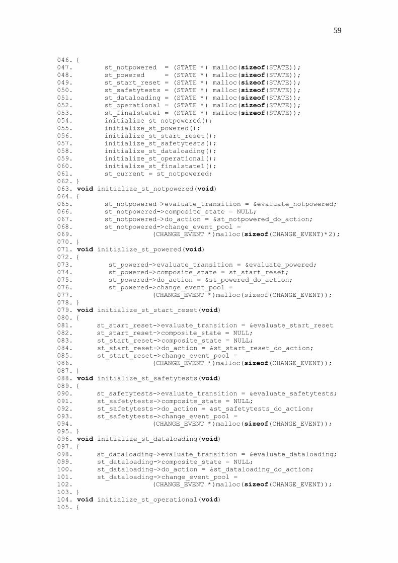
59
046. {
047. st_notpowered = (STATE *) malloc(sizeof(STATE));
048. st_powered = (STATE *) malloc(sizeof(STATE));
049. st_start_reset = (STATE *) malloc(sizeof(STATE));
050. st_safetytests = (STATE *) malloc(sizeof(STATE));
051. st_dataloading = (STATE *) malloc(sizeof(STATE));
052. st_operational = (STATE *) malloc(sizeof(STATE));
053. st_finalstate1 = (STATE *) malloc(sizeof(STATE));
054. initialize_st_notpowered();
055. initialize_st_powered();
056. initialize_st_start_reset();
057. initialize_st_safetytests();
058. initialize_st_dataloading();
059. initialize_st_operational();
060. initialize_st_finalstate1();
061. st_current = st_notpowered;
062. }
063. void initialize_st_notpowered(void)
064. {
065. st_notpowered->evaluate_transition = &evaluate_notpowered;
066. st_notpowered->composite_state = NULL;
067. st_notpowered->do_action = &st_notpowered_do_action;
068. st_notpowered->change_event_pool =
069. (CHANGE_EVENT *)malloc(sizeof(CHANGE_EVENT)*2);
070. }
071. void initialize_st_powered(void)
072. {
073. st_powered->evaluate_transition = &evaluate_powered;
074. st_powered->composite_state = st_start_reset;
075. st_powered->do_action = &st_powered_do_action;
076. st_powered->change_event_pool =
077. (CHANGE_EVENT *)malloc(sizeof(CHANGE_EVENT));
078. }
079. void initialize_st_start_reset(void)
080. {
081. st_start_reset->evaluate_transition = &evaluate_start_reset
082. st_start_reset->composite_state = NULL;
083. st_start_reset->composite_state = NULL;
084. st_start_reset->do_action = &st_start_reset_do_action;
085. st_start_reset->change_event_pool =
086. (CHANGE_EVENT *)malloc(sizeof(CHANGE_EVENT));
087. }
088. void initialize_st_safetytests(void)
089. {
090. st_safetytests->evaluate_transition = &evaluate_safetytests;
091. st_safetytests->composite_state = NULL;
092. st_safetytests->do_action = &st_safetytests_do_action;
093. st_safetytests->change_event_pool =
094. (CHANGE_EVENT *)malloc(sizeof(CHANGE_EVENT));
095. }
096. void initialize_st_dataloading(void)
097. {
098. st_dataloading->evaluate_transition = &evaluate_dataloading;
099. st_dataloading->composite_state = NULL;
100. st_dataloading->do_action = &st_dataloading_do_action;
101. st_dataloading->change_event_pool =
102. (CHANGE_EVENT *)malloc(sizeof(CHANGE_EVENT));
103. }
104. void initialize_st_operational(void)
105. {
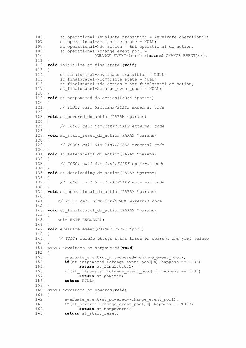
106. st_operational->evaluate_transition = &evaluate_operational;
107. st_operational->composite_state = NULL;
108. st_operational->do_action = &st_operational_do_action;
109. st_operational->change_event_pool =
110. (CHANGE_EVENT*)malloc(sizeof(CHANGE_EVENT)*4);
111. }
112. void initialize_st_finalstate1(void)
113. {
114. st_finalstate1->evaluate_transition = NULL;
115. st_finalstate1->composite_state = NULL;
116. st_finalstate1->do_action = &st_finalstate1_do_action;
117. st_finalstate1->change_event_pool = NULL;
118. }
119. void st_notpowered_do_action(PARAM *params)
120. {
121. // TODO: call Simulink/SCADE external code
122. }
123. void st_powered_do_action(PARAM *params)
124. {
125. // TODO: call Simulink/SCADE external code
126. }
127. void st_start_reset_do_action(PARAM *params)
128. {
129. // TODO: call Simulink/SCADE external code
130. }
131. void st_safetytests_do_action(PARAM *params)
132. {
133. // TODO: call Simulink/SCADE external code
134. }
135. void st_dataloading_do_action(PARAM *params)
136. {
137. // TODO: call Simulink/SCADE external code
138. }
139. void st_operational_do_action(PARAM *params)
140. {
141. // TODO: call Simulink/SCADE external code
142. }
143. void st_finalstate1_do_action(PARAM *params)
144. {
145. exit(EXIT_SUCCESS);
146. }
147. void evaluate_event(CHANGE_EVENT *pool)
148. {
149. // TODO: handle change event based on current and past values
150. }
151. STATE *evaluate_st_notpowered(void)
152. {
153. evaluate_event(st_notpowered->change_event_pool);
154. if(st_notpowered->change_event_pool[0].happens == TRUE)
155. return st_finalstate1;
156. if(st_notpowered->change_event_pool[1].happens == TRUE)
157. return st_powered;
158. return NULL;
159. }
160. STATE *evaluate_st_powered(void)
161. {
162. evaluate_event(st_powered->change_event_pool);
163. if(st_powered->change_event_pool[0].happens == TRUE)
164. return st_notpowered;
165. return st_start_reset;
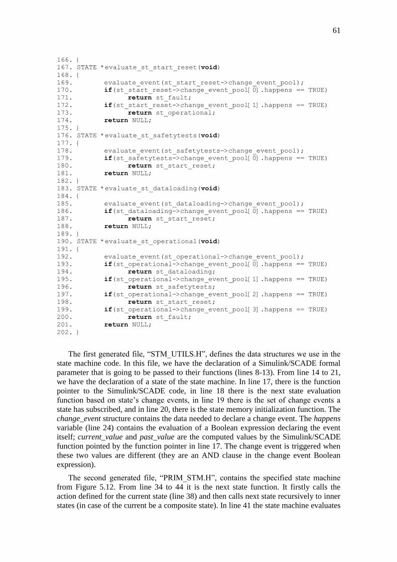
61
166. }
167. STATE *evaluate_st_start_reset(void)
168. {
169. evaluate_event(st_start_reset->change_event_pool);
170. if(st_start_reset->change_event_pool[0].happens == TRUE)
171. return st_fault;
172. if(st_start_reset->change_event_pool[1].happens == TRUE)
173. return st_operational;
174. return NULL;
175. }
176. STATE *evaluate_st_safetytests(void)
177. {
178. evaluate_event(st_safetytests->change_event_pool);
179. if(st_safetytests->change_event_pool[0].happens == TRUE)
180. return st_start_reset;
181. return NULL;
182. }
183. STATE *evaluate_st_dataloading(void)
184. {
185. evaluate_event(st_dataloading->change_event_pool);
186. if(st_dataloading->change_event_pool[0].happens == TRUE)
187. return st_start_reset;
188. return NULL;
189. }
190. STATE *evaluate_st_operational(void)
191. {
192. evaluate_event(st_operational->change_event_pool);
193. if(st_operational->change_event_pool[0].happens == TRUE)
194. return st_dataloading;
195. if(st_operational->change_event_pool[1].happens == TRUE)
196. return st_safetytests;
197. if(st_operational->change_event_pool[2].happens == TRUE)
198. return st_start_reset;
199. if(st_operational->change_event_pool[3].happens == TRUE)
200. return st_fault;
201. return NULL;
202. }
The first generated file, “STM_UTILS.H”, defines the data structures we use in the
state machine code. In this file, we have the declaration of a Simulink/SCADE formal
parameter that is going to be passed to their functions (lines 8-13). From line 14 to 21,
we have the declaration of a state of the state machine. In line 17, there is the function
pointer to the Simulink/SCADE code, in line 18 there is the next state evaluation
function based on state’s change events, in line 19 there is the set of change events a
state has subscribed, and in line 20, there is the state memory initialization function. The
change_event structure contains the data needed to declare a change event. The happens
variable (line 24) contains the evaluation of a Boolean expression declaring the event
itself; current_value and past_value are the computed values by the Simulink/SCADE
function pointed by the function pointer in line 17. The change event is triggered when
these two values are different (they are an AND clause in the change event Boolean
expression).
The second generated file, “PRIM_STM.H”, contains the specified state machine
from Figure 5.12. From line 34 to 44 it is the next state function. It firstly calls the
action defined for the current state (line 38) and then calls next state recursively to inner
states (in case of the current be a composite state). In line 41 the state machine evaluates
the next state to branch. It keeps executing until the evaluated next state is NULL (line
43), or some of the evaluation functions exits the program.
From line 45 to 62 there is the state memory allocation function, each state structure
initialization and, lastly, the assignment of the initial state (line 61). In the case of the
state machine presented in Figure 5.12, this state is the NotPowered one (remember that
an initial node in a UML State Machine is a pseudostate; there is no associated actions
with them. Initial states are only decorative, to graphically represent the actual initial
node).
From line 63 to 118 there is the memory and action state initialization for each
specific state of the state machine. These functions set the STATE struct points to
enable the next_state (line 38) function to execute state behavior independent of a
specific state. Note the change_event_pool initialization. This field is an array of change
events, and the array’s length is equal to the number of state’s outgoing edges. For
example, in line 69 we have the NotPowered state change_event_pool initialization, and
the number of elements to be allocated is two (one for the outgoing edge going to the
Powered state, and the other to the FinalState).
From line 119 to 150 we have the specific do_action for each state, calling the
external Simulink/SCADE code. Due to time restriction, we could not implement the
external code call, but it is straightforward. The do_action for each UML state has as its
implementation the empty activity, which has an opaque action. The Simulink/SCADE
function call is written in the opaque action’s body parameter by hand. The code
generator only gets this specified function call and writes in the do_action body code
specific to each state.
63
6 ASSESMENT AND CONCLUSIONS
This chapter presents in section 6.1 the technical evaluation of every aspect
discussed in this work, highlighting their problems and advantages. In section 6.2, we
discuss further research to continue this work and our proposed approach.
6.1 Technical Evaluation
6.1.1 Model Transformations
6.1.1.1 Understanding
In the beginning, the focus of this work was to perform only the transformation
between A/C ICD and the SysML Design Model. Concerning this transformation, in my
opinion the most critical one, some aspects remain unclear.
Despite the fact of A/C ICD being broadly adopted and well know in AIRBUS,
there are some aspects unclear about its specification. Worst, some aspects of A/C ICD
specification are not described in its specification document (e.g. how to treat some
corner cases on variables types). We still have some flaws when translating A/C ICD
into SysML, for example, when we have a message in the A/C ICD, but its local
parameter field is empty; or yet, when we use some buses not declared in the A/C ICD
(both cases have happened in the ADIRU A/C ICD presented in section 5.1).
Maybe these cases are due to A/C ICD maturity, but there is no document specifying
which constructs can happen (or are missing) for a given maturity level. I suggest
defining this document, relating the three A/C ICD maturity level and the constructs an
A/C ICD compliant to some level must have.
6.1.1.2 Completeness
A/C ICD is quite complete given its purpose, i.e. specifying how an embedded
application interfaces with its equipment. With the new A/C ICD version near to its
publishing this description is going to be even more detailed, containing, for example,
the equipment power supply. A/C ICD completeness made easy its transformation to
SysML. I think that all A/C ICD constructs were well translated into SysML Design
Model, without any prejudice to its data or completeness.
6.1.1.3 Specification
As this work was refined as time has passed, growing fast in complexity, size, and
target domains, we have defined transformation rules in an ad hoc fashion. In my
opinion this was the best way to follow, given the exploratory bias of this work; we did
not want to have a final, closed product, we wanted a research prototype that could
show us the potentials, flaws, and feasibility of a model-based approach to simulation
design of embedded avionics equipment instead. Now that the transformation rules are
consolidated, I suggest specifying them in a more formal fashion (see implementation
for a discussion on that).
6.1.1.4 Implementation
We have implemented the transformation rules in pure Java, summing around
27.000 lines of code entirely written by hand. Java was chosen because in the beginning
the work was small, but, as said before, its size has increased a lot. Currently, given the
size of this work, as well as the complexity of the transformation rules, and the
metamodels used, Java is far from being suitable to a more end-product version. The
Java code is too big, complex, and its legibility is not good. We have not defined code
conventions, prejudicing its manageability. Finally, as Java is not targeted to model
transformations, the transformation rules are hidden in Java code, making very difficult
their understanding.
I suggest implementing a new version of our prototype with ATL (ATLAS
Transformation Language). ATL was designed to handle model transformations, has a
concise notation to that, making quite evident the transformation rules between
metamodels. I think that our tool quality, manageability, and understanding would
dramatically increase with this new coding in ATL. In addition, using ATL makes our
tool closer to both TOPCASED and MDE (Model-Driven Engineering) communities.
6.1.2 SysML Design and Simulation Models
6.1.2.1 Understanding
Both SysML Design and Simulation models were very understandable to everybody
that was in contact with them. It contains clear and simple concepts, and in my opinion,
this was achieved due to the definition of both the UP2A and SFPR profiles. The
separation of design and simulation architectural levels was very clear, and how we
trace both levels. The internal mapping structure between messages, signals, and local
parameters is straightforward too. As we have adopted a block-oriented fashion to
specify in SysML the A/C ICD constructs, and everybody in the simulation department
has notions of Simulink/SCADE, both SysML Design and Simulation models
understanding is straightforward.
Concerning the empty activity and the UML Equipment State Machine we have
received a feedback from a team member of the AMISA project saying that the
interaction with the simulation platform scheduler was not clear, and how and when the
do_action is executed. This is easily fixed just defining new stereotypes in the UP2A
profile to represent the simulation scheduler, but it is not needed to do so. As soon as
these rules are coded in the code generator, and the Simulation Designer creating the
UML State Machine is aware of them, they are useless, being only a notational
overhead decreasing model legibility and conciseness.
6.1.2.2 Abstraction
Both SysML Design and Simulation models have an adequate level of abstraction,
but the internal mapping structure between messages, signals, and local parameters.
These mapping structure contains several blocks, connectors, flow ports that, in my
65
opinion, does not need to be in the model. As discussed internally, we see the
simulation being performed in terms of application variables (or local parameters), not
anymore in terms of signals and messages. Assuming that this work is targeted for long-
term research, I think we can be more aggressive and get rid this information off the
model. If this information is necessary for some analysis, a tool could retrieve it from a
database. Thus, in this approach we only need to connect the model elements in the
SysML models with its internal structure stored in the database. This database approach
is suitable, in my opinion, because SysML models are good at system specification, but
are quite bad in information storage. Putting the mapping structure in the SysML model
is the wrong way of dealing with them. I think that this clear separation of modeling
data and design data is the biggest impeditive of adopting model-based techniques in
industry today, and I do not see any solution to integrate models with a relational
database. This is another research direction that can be conducted in the frame of
INSIDE or even AMISA.
6.1.2.3 Implementation
I have the same considerations as presented in section 6.1.1.4. We should implement
the transformation rules in ATL, not in Java. In the TOPCASED project there is
available a set of APIs to handle SysML models, and they can be easily integrated with
ATL, as TOPCASED already does. Nevertheless, I think that it is best to use a text-to-
model tool to generate SysML from A/C ICD CSV files. Unfortunately, these tools are
not widespread available in the community, they are rather incubated projects yet.
6.1.3 MICD and Simulation Code Generation
6.1.3.1 Understanding
The MICD generation is straightforward, and its specification is good. Again, it fails
in specifying corner cases, but it is possible to infer these cases. As MICD are broadly
adopted, there is no problem of understanding how it is generated from SysML models.
Concerning code generation, we have not closed how to specify when and how a
state branches to other, thus, affecting code generation. A better specification and
algorithms that are more detailed are left as future work.
6.1.3.2 Completeness
The MICD code generation supports only the minimum features to pass validation in
the MICD Studio. Other data that we have in the A/C ICD may not be generated in the
MICD due to this point. As we wanted to reconstruct only the joining keys to create a
proof-of-concept, this is fine to our objectives.
Concerning simulation code generation, it is missing how to evaluate the next state
based on declared change events, and the connection with Simulink/SCADE. The
former it lacking the formalization of change events specification, and the latter is just a
matter of gluing the code inserted on the opaque action’s body field. In addition, it is
needed to declare the MICD variables in the generated C code, which is quite
straightforward too.
6.1.3.3 Implementation
I have implemented everything in Java, and, in the case of MICD generation, I think
this is the best way of doing so right now. We have used the APACHE POI API to
generate the Excel file, being very abstract and easy to use. Using such an API avoids
the problem of byte serialization and compliance with the Microsoft Excel binary
format. I do not recommend using a model-to-text transformation in this case.
Regarding simulation code generation, I suggest using Acceleo tool to do that. It is
very easy and high level, being perfect to code generation from well-defined
metamodels. Unfortunately, C code generation from UML State Machines is not
complete in Acceleo, but, in our case, we have a very simple code generation process,
not requiring the implementation of all UML metamodel constructs related to state
machines.
6.1.4 Integrated Model-Based Design and Simulation Process
6.1.4.1 Understanding
The idea of integrating design and simulation in a more formal fashion (based on
SysML models in our approach) received an excellent reception from AIRBUS
engineers, both from the Design Office and the Avionics Simulation Products
Department. Both departments recognize the lack of formalism in integrating design
and simulation artifacts, and recognize the bad outcomes associated with it. Thus, this
approach is completely feasible in the middle or long-terms.
AIRBUS is a strong supporter of SysML and TOPCASED, so there is somehow a
broad knowledge of it in the company; SysML is not seen as black magic or an
unfeasible academic proposal. In this way, a model-based approach using SysML has
the potential to decrease the adoption barrier and resistance to changes in status quo.
Certainly, it will be necessary to provide training on SysML and the new process, and
highlight that more formalism is beneficial to the aeronautic domain, helping engineers
to make their jobs better and more reliable.
I suggest organizing meetings with AMISA team to discuss common problems and
solutions. AMISA has common problems and solution to INSIDE and this discussion
can be very beneficial. In addition, it is the perfect opportunity to integrate design and
simulation from the beginning with SysML.
6.1.4.2 Completeness
In this work, we have approached the process of importing current design artifacts
into SysML, and selecting the ones we want to simulate, and, finally, generating the
current simulation artifact from SysML. We have not approached how requirements
engineering could be integrated in this approach, or event testing of the created models.
Current tools for requirements engineering, e.g. Telelogic DOORS, support SysML
models, creating requirement version management, as well as model artifacts.
Nonetheless, it is still necessary to adopt how simulation requirements would be
described with such an approach. Clearly, this is completely feasible. Regarding testing,
it could be performed over the generated or hand written code from the SysML model,
or over the SysML model, through the UML Profile for Testing or OCL constraints.
The Cockpit Group in the Design Office (EDYAK) already uses Telelogic DOORS
to handle requirements, and they have some integration with SysML models. It could be
67
interesting to discuss with them how their process is. Testing with UML/SysML model
is still an open research problem, and there is no close solution to that. For me it seems
interesting to express consolidated test procedures with OCL representing structural
constraints that the model must respect, and exploratory test procedures with the UML
Profile for Testing. From this profile, we could generate unit tests to test the generated
code. Another open problem is how to integrate Simulink/SCADE models with these
testing procedures.
6.1.4.3 Suitability
An integrated approach for design and simulation is completely suitable and
necessary with the increase in aircraft design complexity. Current techniques based on
textual documents, and ad hoc communication and traceability is far from efficiently
manage this complexity. Any approach integrating design and simulation in a more
formal fashion is more than desirable, it is essential.
In our approach, the bottleneck is clearly two: the internal mapping from messages
to signals and local parameters, and the CASE tool we have adopted (TOPCASED). As
discussed before, the internal mapping is an overhead on abstraction not desirable when
systems are getting more complex, thus, making this mapping even more obfuscated in
SysML. Concerning TOPCASED, it is an excellent experimentation tool, and should be
used in AIRBUS research projects, given its flexibility due to its open-source nature,
but I think that it cannot be used yet in production. The environment is very unstable,
with many beta tools working together, and the modeling area and properties panels’
sizes are not good to modeling (we can solve that using two monitors side-by-side).
AMISA has adopted Telelogic Rhapsody as its CASE tool, and I think this is a good
choice. It is completely integrated with DOORS, very robust, being in the market for
year. Again, I recommend TOPCASED for R&T projects, while Rhapsody for
production.
6.2 Contributions and Future Work
Our contributions are:
An approach enabling integrated design and simulation in a model-based
fashion. With our approach, all simulation and design elements are traced,
enabling further impact analysis between these two architectural levels. In
addition, our approach removes all redundancies between simulation and
design, given that a SysML model can be reused by other model, always
referencing the source one;
Transformation and representation of aircraft design and simulation data in a
more convenient formalism, moving from textual-based to model-based
representations through the SysML Design and Simulation models, as well
as the UP2A and SFPR UML profiles;
Separation and better understanding of simulation model and simulation
platform responsibilities, in specific the simulation scheduler and the
AP2633 state machine;
Definition and first algorithms for simulation code generation from SysML
Simulation models and its integration with Simulink/SCADE, through the
mechanism of change events;
Development of a tool prototype to perform and show the feasibility of our
approach. One of the main difficulties to introduce new technology and to
break status quo is to convince people that the new way of doing things is
better, and with a tool prototype, this was easier.
Another contribution is the further research and development this work opens:
Full simulation code generation from SysML Simulation models and its
further integration with Simulink/SCADE. It is needed to define the change
events semantics, its relation with the AP2633 state machine, and the best
way to call Simulink/SCADE code. It would be interesting to use Acceleo to
implement the code generator;
Implementation of the model-to-model transformation (A/C ICD-AP2633 to
SysML Design Model, then to SysML Simulation Model) rules in ATL, the
text-to-model transformations (A/C ICD CSV file to A/C ICD-AP2633
metamodel), and model-to-text transformations (SysML Models to MICD
Excel sheet). This would improve our tool, making easier to perform
evolution, manageability, testing, and production;
Integration of relational databases with SysML models, enabling to store
low-level data into databases, improving the abstraction of the SysML
models. This is important to avoid using the SysML model as a data
repository, and to improve impact analysis and engineering with SysML;
Full SysML Simulation model execution in SysML to enable exploratory
modeling, reducing the simulation design cycle by performing partial
simulations before OCASIME. It is necessary to define the subset of SysML
we are going to use, and to code its virtual machine;
Devising design and simulation process for requirements management, and
artifacts control integrated with OSMOSE.
69
REFERENCES
ADVISORY COUNCIL FOR AERONAUTICS RESEARCH IN EUROPE. : Strategic
Research Agenda 1. Volume 2, [S.l.], 2002.
AIRBUS SAS. M2633 Module 2: Shared Simulation Models Design Rules. Draft 4.
Toulouse, 2009.
AIRBUS SAS. AP2633: Develop, Integrate and Validate Shared Simulation Models.
Issue C. Toulouse, 2008.
AIRBUS SAS. X0WD0805765: Project INSIDE : INtegrated Simulation Into DEsign.
R&T Project Agreement. Toulouse, 2008b.
AIRBUS SAS. RP0816448: AMISA Method – Technical Report. Toulouse, 2008c.
AIRBUS SAS. UG0600603: OSMOSE Guide méthodologique outils : métier
équipement. Issue 3. Toulouse, 2007a.
AIRBUS SAS. V00RP0716320: A350 ISCD Policy. Issue 1. Toulouse, 2007b.
AIRBUS SAS. 509.0025/2003: AP2633 Model ICD Guideline. Technical Report.
Toulouse, 2006.
AIRBUS SAS. L00ME0315182: How to Fill the Column “Aircraft Signal Name” in
Model ICD. Memorandum. Toulouse, 2003.
AIR TRANSPORT ASSOCIATION. 99100P: Spec 100: Manufacturers’ Technical
Data. Revision 1999. Washington, 1999.
BAKER, L.; CLEMENTE, P.; COHEN, B.; PERMENTER, L.; PURVES, B.;
SALMON, P. Foundational Concepts for Model Driven System Design: INCOSE
Model Driven System Design Workgroup. [S.l.], 2000.
BALCI, O. A Methodology for Certification of Modeling and Simulation Applications.
ACM Transactions on Modeling and Computer Simulation. New York: ACM Press,
2001, v. 11, n. 4, p. 352-377.
BRADE, D. A Generalized Process for the Verification and Validation of Models
and Simulation Results. 2003. 239 f. Thesis ( Doctor rerum naturalium ) – Fakültat für
Informatik, Universität der Bundeswehr München, Munich, Germany.
BRIÈRE, D.; TRAVERSE, P. AIRBUS A320/330/340 electrical flight controls – A
family of fault-tolerant systems. In: THE TWENTY-THIRD INTERNATIONAL
SYMPOSIUM ON FAULT-TOLERANT COMPUTING (FCTS’93). FCTS 1993
Digest of Papers. Los Alamitos: IEEE Computer Society Press, 1993, p.616-623.
CLARK, N. Next Delay for A380: A Decade Before Break-Even. The New York
Times. 2006, 19th
October, Business Section. http://www.nytimes.com/2006/10/19/
business/worldbusiness/19iht-airbus.3222866.html. Accessed on July 2009.
CRAIG, I. D. Object-Oriented Programming Languages: Interpretation.
Undergraduate Topics in Computer Science (UTCS) Series. 1st edition. Heidelberger,
Germany: Springer-Verlag, 2007.
DEPARTMENT OF DEFENCE OF AUSTRALIA. : Simulation Verification,
Validation and Accreditation Guide. Canberra, 2005.
DEPARTMENT OF DEFENSE OF UNITED STATES. MG101: Improving the
Composability of Department of Defense Models and Simulations. Santa Monica, 2004.
DISCOVERY CHANNEL. http://www.youtube.com/watch?v=IKBABNL-DDM.
Accessed on July 2009.
ESTEFAN, J. A. Survey of Model-Based System Engineering (MBSE)
Methodologies: INCOSE MBSE Focus Group. Revision A. [S.l.], 2007.
FERREIRA, R.; BRISOLARA, L.; MATTOS, J.; SPECHT, E.; COTA, E.; CARRO, L.
Engineering Embedded Software: from Application Modeling to Software
Synthesis. In: GOMES, L.; FERNANDES, J. (Org.). Behavioral Modeling for
Embedded Systems and Technologies: Applications for Design and Implementation.
Hershey: IGI Publishing Group, 2009.
FLIGHT DAILY NEWS. Paris Air Show: Perception By Wire. Flight Daily News.
2009. http://www.flightglobal.com/articles/2009/06/08/327191/paris-air-show-
perception- by -wire.html, Accessed on July 2009.
FLIGHT INTERNATIONAL. A340 Described: Architecture Refinement for A340
FBW. Flight International Magazine. [S.l.] : [S.n.], n.5, 11 June, 1991.
FORSBERG, K.; MOOZ, H. The Relation of System Engineering to the Project Cycle.
In: JOINT CONFERENCE OF THE NATIONAL COUNCIL ON SYSTEMS
ENGINEERING (NCOSE) AND THE AMERICAN SOCIETY FOR ENGINEERING
MANAGEMENT (ASEM) (ASEM’91). Proceedings of the 1991 ASEM.
Chattanooga, TN, USA: ASEM Press, 1991, p. 1-12.
IEEE COMPUTER SOCIETY. IEEE Std 1516.2-2000: IEEE Standard for Modeling
and Simulation (M&S) High Level Architecture (HLA) – Object Model Template
(OMT) Specification. Std 1516.2-2000. New York, 2001.
IEEE COMPUTER SOCIETY. IEEE Std 1220-2005: IEEE Standard for Application
and Management of the Systems Engineering Process. Std 1220-2005 (Revision of
IEEE Std 1220-1998). New York, 2005.
LARMAN, C. Applying UML and Patterns: An Introduction to Object-Oriented
Analysis and Design and Iterative Development. 3rd
edition. New Jersey, USA:
Prentice Hall, 2004.
MARTIN, J. N. Overview of the EIA 632 Standard: Processes for Engineering a
System. In: 17th
DIGITAL AVIONICS SYSTEMS CONFERENCE (DASC’98).
Proceedings of the 17th
AAIA/IEEE/SAE DASC. [S.l.]: IEEE Computer Society
Press, 1998, v.31, n.1, p. B32 1-9 vol. 1.
71
MURPHY, C. A. The Definition and Potential Role of Simulation Within an Aerospace
Company. In: 2001 WINTER SIMULATION CONFERENCE (WSC’01). Proceedings
of the IEEE WSC 2001. [S.l.]: IEEE Computer Society Press, 2001, v. 1, p. 829-837.
NATIONAL AERONAUTICS AND SPACE ADMINISTRATION. NASA-STD-7009:
Standard for Models and Simulations. 07-11-2008. Washington, 2008.
OBJECT MANAGEMENT GROUP. formal/06-01-01: Meta Object Facility (MOF)
Core Specification. Version 2.0. [S.l.], 2006a.
OBJECT MANAGEMENT GROUP. formal/2008-04-03: Meta Object Facility (MOF)
2.0 Query/View/Transformation Specification. Version 1.0. [S.l.], 2008a.
OBJECT MANAGEMENT GROUP. ormsc/2001-07-07, [S.l.], 2001.
OBJECT MANAGEMENT GROUP. formal/06-05-01: Object Constraint Language.
Version 2.0. [S.l.], 2006b.
OBJECT MANAGEMENT GROUP. formal/2008-11-02: OMG Systems Modeling
Language (OMG SysMLTM
). Version 1.1. [S.l.], 2008b.
OBJECT MANAGEMENT GROUP. formal/2009-02-04: OMG Unified Modeling
LanguageTM
(OMG UML), Infrastructure. Version 2.2. [S.l.], 2009a.
OBJECT MANAGEMENT GROUP. formal/2009-02-02: OMG Unified Modeling
LanguageTM
(OMG UML), Superstructure. Version 2.2. [S.l.], 2009b.
RATIONAL SOFTWARE. TP 165A: Rational Unified Process®
for Systems
Engineering: RUP® SE1.1. Version 5/02. Cupertino, 2002.
RODRÍGUEZ-DAPENA, P. Software Safety Certification: A Multidomain Problem.
IEEE Software. Los Alamitos : IEEE Computer Society Press, 1999, v. 16, n. 4, p. 31-
38.
ROQUES, P.; VALLÉE, F. De l’analyse des besoins à la conception en Java. 2éme
édition. Paris : Éditions Eyrolles, 2003.
SARGENT, R. G. Verification and Validation of Simulation Models. In: 2008
WINTER SIMULATION CONFERENCE (WSC’08). Proceedings of the 39th
IEEE/ACM WSC 2008. Piscataway: IEEE Computer Society Press, 2007, p. 124-137.
SILBERSCHATZ, A.; KORTH, H. F.; SUDARSHAN, S. Database Systems
Concepts. 4th
ed. New York: McGraw-Hill Science/Engineering/Math, 2001.
TRAVERSE, P.; LACAZE, I.; SOUYRIS, J. Airbus Fly-By-Wire : A Total Approach
To Dependability. In: 18th
WORLD COMPUTER CONGRESS (WCC’04).
Proceedings of the IFIP WCC 2004. Toulouse: Springer Boston, v. 156/2004, p. 191-
212.
TOPCASED Modeling and Simulation CASE Tool. The Open-Source Toolkit for
Critical Systems. Version 2.5, http://www.topcased.org. Accessed on July 2009.
VOAS, J. Certifying Software for High-Assurance Environments. IEEE Software. Los
Alamitos: IEEE Computer Society Press, 1999, v. 16, n. 4, p. 48-54.
WEILKIENS, T. Systems Engineering with SysML/UML: Modeling, Analysis,
Design. 1st ed. Amsterdam: The Morgan Kaufmann/OMG Press, 2008.