Embed Size (px)
Citation preview
Naval Engineers Journal, May 1994 77
LCDR. NORBERT H. DOERRY, USN & LCDR. JAMES C. DAVIS, USN
Integrated Power System for Marine Applications
THE AUTHORS
LCdr. Norbert H. Doerry, USN, is an Engineering Duty Officer developing the Integrated Power System within the Advanced Sur- face Machinery Programs (Naval Sea Systems Command, SEA 03R2). Following graduation from the United States Naval Acade- my with a BSEE degree in 1983, LCdr. Doerry served as Gunnery and Fire Control Officer on Deyo (DD-989). He then reported to MIT where he earned a SMEECS degree, a naval engineers de- gree, and a Ph.D. in naval electrical power systems. LCdr. Doerry is qualified as a Surface Warfare Officer and has been awarded the Navy Achievement Medal and the 1989 NAVSEA Award in Naval Construction and Engineering. LCdr. James C. Davis, USN, earned a BSME from the United States Navy Academy and the SMEECS and naval engineer degrees from MIT. He is a member of ASNE and SNAME. He has served aboard Briscoe (DD-977), at two shipyards and as an exchange officer with the Royal Australian navy. He is currently the Integrated Power System Assistant program manager for the Advanced Surface Machinery Programs (Naval Sea Systems Command, SEA-03R2).
ABSTRACT
The U.S. Navy has shifted priority from designing systems that offer increased capability, to systems which are more affordable, but enable improved performance. To address the emphasis on affordability, the Advanced Surface Machinery (ASM) Programs and the Affordability Through Commonality (ATC) program are proposing ship systems composed of common modules employing standardized parts. This paper describes the Integrated Power System (IPS) which provides electrical power for both propulsion and ship service loads for a wide range of ship applications including submarines, surface combatants, aircraft carriers, amphibious ships, auxiliary ships, sealift and high value commercial ships. IPS consists of an architecture and a family of modules from which affordable and high performance configurations can be developed for the full range of ship applications. In most configurations, IPS reduces the number of prime movers and divides ships into electrical zones controlled in a modular fashion. Cost reductions are realized in acquisition, training, manning, maintenance and other logistic support areas.
INTRODUCTION
This paper describes the Advanced Surface Machinery (ASM) Program's Integrated Power System (IPS) from which affordable and technically viable propulsion and ship service power system configurations can be assembled for a wide range of ship applications including aircraft carriers, submarines, surface combatants, large amphibious ships, large naval auxiliary ships and high value commercial ships. IPS reflects the post Cold War shift of design priority from improving performance to reducing costs through eight affordability initiatives (Graham, 1991):
• Extend Architectural Advantage • Promote Commonality • Exploit Producibility • Reduce Infrastructure • Reduce Component Costs • Reduce Manning • Reduce Energy Costs • Reduce Combat System Costs
BACKGROUND
The United States Navy ship design and construction process is undergoing revolutionary changes. The smaller fleet and accompanying lower budgets resulting from the end of the Cold War necessitate a corresponding reduction in the ship design and construction infrastructure within the Navy, as well as innovative initiatives for keeping acquisition and life-cycle costs down for relatively small classes of ships procured at a low rate. New ship design methods requiring fewer people and resulting in more affordable ships are needed. Some of the initiatives currently pursued by the Navy are Product Oriented Design and Construction (PODAC), Product Information Management (PIM), Three Dimensional Computer Aided Design (3-D CAD) and Affordability Through Commonality (ATC). Within the Naval Sea Systems Command (NavSea), these initiatiives are being implemented under the CAD 2 program (Billingsley et al., 1992), the Affordability Through Commonality program (Cecere et al., 1993) and the Advanced Surface Machinery
INTEGRATED POWER SYSTEM DOERRY & DAVIS
78 Naval Engineers Journal, May 1994
Programs. To date, these initiatives have largely preserved existing
HM&E system architectures. In many cases, these existing architectures are incompatible with producible ship designs. For example, the traditional radial electrical distribution system requires many main bus and longitudinal feeder cables to cross construction boundaries. Typically, these cables do not employ connectors at construction boundaries and must therefore be pulled after the ship has been assembled. The ATC program estimates the cost of performing this work on board is about twice that if the work could be accomplished while the ship large assemblies are “on block.” Several efforts are currently underway to change HM&E system architectures to reflect the new ship design and construction process. For example, the Zonal Electrical Distribution System (ZEDS), one of the ASM Programs, reduces the acquisition cost of ship service electrical distribution by replacing the multiple main feeders with port and starboard busses and zonal load centers (Petry and Rumburg, 1993). Another example is a proposal for a zonal firemain system to reduce cost, maintain survivability and simplify construction boundary interfaces (Shiffler, 1993).
To improve ship producibility and enhance affordability on a larger scale, ASM is developing an Integrated Power System for the generation, distribution and use of ship service and electrical propulsion power in ship applications. A cornerstone of IPS is the use of electricity as a common means for transmitting both propulsion (electric drive) and ship service power throughout the ship. Electric propulsion offers many producibility benefits, including the elimination of long shaft lines requiring alignment across many ship construction zones; the ability to align rotating machinery in the shop environment rather than onboard ship and the reduction in the total number of prime movers required by using the same engines for both ship service and propulsion power.
Electric propulsion is not new. The history of electric drive in marine applications is well documented, as is the current use of electric machinery in cruise liners, ice breakers, and ferries (Apriainen et al., 1993; Beverley, 1992; Hopkins, 1991). To meet the new affordability challenges however, IPS differs from previous electric drive implementations in the following ways:
• Designed for applicability across a wide range of ship applications.
• Module based approach based on the Integrated Power Architecture (IPA).
• Standardized power and control interfaces for machinery modules.
• DC distribution using solid state fault protection • High Frequency AC machines.
These features of IPS are described in greater detail in the following sections.
IPS DESCRIPTION
Designing an Integrated Power System configuration for a particular ship consists of tailoring modules to meet specific performance requirements. Since the ship applications can vary
considerably, a key to the success of IPS is the ability to sufficiently define interface standards between modules to enable the design, construction and integration of machinery modules independent of the ultimate configuration. An IPS Design Data Sheet will describe the tailoring process normally carried out jointly by an IPS System Integration Agent (SIA) and the Ship Acquisition Program Manager (SHAPM).
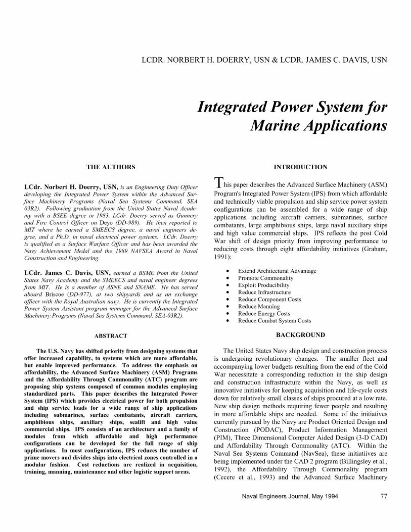
IPS is designed around a product breakdown structure. The largest entity, called a configuration, corresponds to the entire power generation, power distribution, power control, load structure and propulsion system of a ship. A configuration is composed of a number of modules tailored to meet ship performance requirements. It consists of specific machinery and equipment adhering to strict interface standards for power, information and control. A module in turn is composed of submodules and packages.
A package is an integration of components and piece parts not normally mounted on a common sub-base. Examples of packages include cable runs, control software, bus duct and piping. A submodule is an integration of components and piece parts mounted on a common sub-base. Examples of submodules include a lube oil submodule and a gas turbine generator submodule.
Components are equipment or software assembled in a single process lane from multiple piece parts and other components. Examples include an ICR gas turbine, generator and motor. Piece parts are the lowest product level and represent a finished part, either manufactured from raw stock or used off-the-shelf (Bevins et al., 1992). Figure 1 demonstrates this breakdown.
INTEGRATED POWER ARCHITECTURE (IPA)
The Integrated Power Architecture (IPA) provides the framework for partitioning the equipment and software of IPS into modules. IPA defines six functional elements and the power, control and information relationships between them. Every IPS module corresponds to one of the IPA functional elements. A power relationship is one involving the transfer of electrical power between two functional elements. A control relationship refers to the transmission of commands from one functional element to another while an information relationship refer to the transmission of data from one functional element to another. The six functional elements are Power Generation, Power Distribution, Power Conversion, Power Load, Energy Storage and System Control.
• Power Generation: A Power Generation Functional Element converts fuel into electrical power. The electrical power is transferred to one or more Power Distribution Functional Elements. A Power Generation Functional Element exchanges control and information signals only with System Control Functional Elements. An associated Power Generation Module might typically consist of either a gas turbine or diesel engine, a generator, a rectifier, auxiliary support submodules and module controls. Other possible technologies include solar cells, fuel cells, or other direct energy conversion concepts.
DOERRY & DAVIS INTEGRATED POWER SYSTEM
Naval Engineers Journal, May 1994 79
Figure 1. IPS Product breakdown.
•••• Power Distribution:
A Power Distribution Functional Element transfers electrical power between other Functional Elements. Control and information signals can be exchanged only with System Control Functional Elements. An associated Power Distribution Module might typically consist of bus duct, cables, switchgear and fault protection equipment.
•••• Power Conversion: A Power Conversion Functional Element converts electrical power from the form of one Power Distribution Functional Element to the form of another Power Distribution Functional Element. Power may be transferred only to and from Power Distribution Functional Elements. Control and Information signals can be exchanged only with System Control Functional Elements. An associated Power Conversion Module would typically consist of a solid state power converter. Another possibility is a motor-generator set. The power conversion equipment associated with generators and motors are, however, part of the Power Generation and Power Load Functional Elements respectively. They are not considered part of a Power Conversion Functional Element.
•••• Power Load: A Power Load Functional Element is a user of electrical power received from one or more Power Distribution Functional Elements. A Power Load may optionally deliver power to one or more Power Distribution Functional Elements under transient conditions (regenerative braking for example). A Power Load may exchange control and information signals with System Control Functional Elements and external (non-IPS) systems. Associated Power Load Modules include Propulsion Motors and ship service loads.
• Energy Storage: An Energy Storage Functional Element stores energy. Power is transmitted to and from one or more Power Distribution Functional Elements via electric power. An Energy Storage Functional Element exchanges control and information signals with only System Control Functional Elements.
•••• System Control: A System Control Functional Element consists of the software necessary to coordinate multiple other Functional Elements. A System Control Functional Element receives information from other functional elements and possibly external (non-IPS) systems. Similarly, a System Control Functional Element may receive control commands from or negotiate control actions with external systems and other functional elements. A System Control Functional Element resides on an external distributed computer system and therefore does not have a power interface. The IPS System Control Modules will receive processing and network services from the Standard Monitoring and Control System (SMCS), another ASM program.
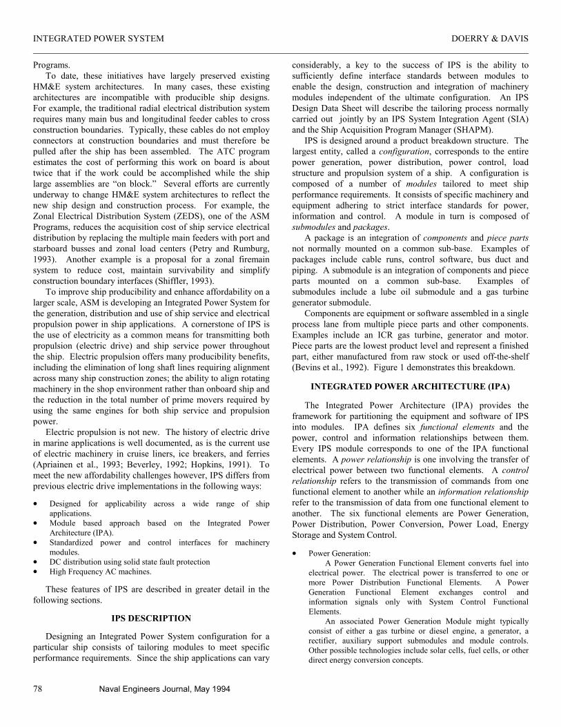
An example of how IPA and the associated IPS modules would be applied to a ship configuration is shown in Figure 2. Distinguishing features of IPA are the principles that modules transfer power only to and from power distribution modules and that modules transfer information and control signals only to and from system control modules. Restricting the power, information and control interactions to only one other module type simplifies the integration of modules into configurations.
INTEGRATED POWER SYSTEM DOERRY & DAVIS
80 Naval Engineers Journal, May 1994
Figure 2. Integrated power architecture.
Integrating a module into an IPS configuration consists of ensuring the module’s power interface is compatible with one or more power distribution modules. Control and information interfaces must be compatible with one or more system control modules.
Each power distribution module is associated with a family of other modules with which it shares power interface standards. Similarly, each system control module is associated with a family of modules with which it shares control and information interface standards. Developing a configuration entails tailoring modules from the various families of modules to meet ship performance requirements. The tailoring process will be detailed in an IPS Design Data Sheet and in Module Characterization Sheets.
IPS MODULES
To date, the ASM Programs have identified families of modules compatible with four Power Distribution Modules (PDM-1, PDM-2, PDM-3 and PDM-4) and two System Control Modules (PCON-1 and PCON-2). The characteristics of the power interface standards for these modules are shown in Table
1. In identifying the families of modules, ASM is ensuring that viable configurations can be assembled from the minimum number of modules for the broad range of IPS supported applications. However, ASM is expending resources primarily on those modules supporting the SC-21 design process.
The maximum voltage for PDM-1 is currently 750 volts. This value is dictated by the voltage rating of the Insulated Gate Bipolar Transistors (IGBT) available for power conversion devices in the various modules. An engineering challenge associated with this choice is the development of a fault protection strategy for rated currents up to 32,000 amps. An alternate power conversion strategy employing IGBTs configured in series (to enable raising the bus voltage and lowering the current) is simply too costly and restricts the ability to use common inverter components across all of the modules. The future development of MOS Controlled Thyristors (MCT) with higher voltage ratings promises the ability to eventually raise the maximum voltage for PDM-1 and thereby reduce current levels, reduce transmission losses and improve system stability.
The four power distribution modules are composed of cable packages, bus duct packages and switchgear submodules:
• Cable and Bus Duct Packages Cable packages are currently anticipated only for PDM-3 and consist of the electrical cables, cable hangers and other associated hardware for distributing ship service power between a Power Generation module or a Power Conversion module and a ship service Power Load. Bus Duct packages serve the same function as Cable Packages for PDM-1 and PDM-2. ASM anticipates the net cost of acquiring and installing bus duct will be less than the cost of cable for these two distribution modules. If ongoing studies prove bus duct is not cost effective, ASM will use cable packages for PDM-1 and PDM-2 as well.
• Switchgear Submodule Switchgear submodules include switchgear, fault protection equipment, sensors and associated controls. PDM-1 and PDM-2 will not employ conventional air-magnetic circuit breakers capable of interrupting fault current. IPS requires all modules providing power to these Power Distribution Modules to have the capability to quickly de-energizing faulted interfaces and limit fault currents. PDM-1 and PDM-2 will perform fault isolation only when faulted components are de-energized. PDM-3 is expected to use either conventional circuit breakers or circuit breakers of an advanced design.
POWER GENERATION MODULES
Four Power Generation Modules currently under consideration by ASMP are listed in Table 2. Of these four, PGM-1, PGM-2 and PGM-3 are undergoing concept level design. These Power Generation Modules are capable of providing power to both PDM-1 and PDM-2. PGM-1 can provide power to both power distribution modules at the same time, although the maximum power provided to PDM-2 is limited by the number of ship service rectifiers specified as a tailoring option. Other tailoring options include the presence of an APU starting submodule and the amount of power filtering capacitance added to the Power Distribution interfaces.
DOERRY & DAVIS INTEGRATED POWER SYSTEM
Naval Engineers Journal, May 1994 81
Table 1. Power distribution module interface standards.
Property PDM-1 PDM-2 PDM-3 PDM-4 Purpose Propoulsion Power
Transmission Port and Starboard Ship Service Power
Busses.
Zonal AC Ship Service
Distribution
Pulse Power Weapons
Applications Frequency DC DC 60 Hz. 3 Phase DC Nominal Voltage Possibly Variable
up to 750 750 450 TBD
Voltage Tolerance
TBD TBD MIL-STD-1399 TBD
Grounding Method
Ungrounded Ungrounded Ungrounded TBD
Existing Standard None None MIL-STD-1399 Section 300A
None
PGM-3 consists of an Allison 501 ship service gas turbine
generator set with an additional controlled rectifier submodule. In the future, a high frequency Permanent Magnet generator may replace the 60 Hz. generator; thereby enabling the use of the same rectifier and filter components used in PGM-1.
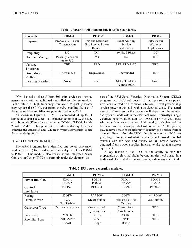
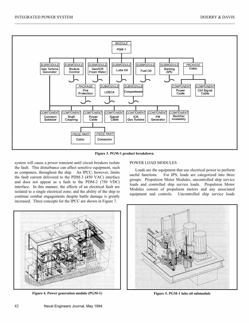
As shown in Figure 4, PGM-1 is composed of up to 11 submodules and packages. To enhance commonality, the lube oil submodule (Figure 5) is common to PGM-1, PMM-1, PMM-2 and PMM-3. Design efforts are also underway to either combine the generator and ICR fresh water submodules or use the same design for both.
POWER CONVERSION MODULES
The ASM Programs have identified one power conversion module (PCM-1) for transferring electrical power from PDM-2 to PDM-3. This module, also known as the Integrated Power Conversion Center (IPCC), is currently under development as
part of the ASM Zonal Electrical Distribution Systems (ZEDS) program. An IPCC will consist of multiple solid state power inverters mounted on a common sub-base. It will provide ship service power to the loads within an electrical zone. The actual number of inverters in this module will depend on the number and types of loads within the electrical zone. Normally a single electrical zone would contain two IPCCs to provide vital loads with redundant power sources. Additionally, loads that perform better or cost less when provided with other than 60 Hz. power, may receive power of an arbitrary frequency and voltage (within a range) directly from the IPCC. In this manner, an IPCC can give large motors a soft-start capability and provide combat systems with the type and quality of DC power normally obtained from power supplies internal to the combat system equipment.
A key feature of the IPCC is the ability to stop the propagation of electrical faults beyond an electrical zone. In a traditional electrical distribution system, a short anywhere in the
Table 2. IPS power generation modules.
PGM-1 PGM-2 PGM-3 PGM-4 Power Interface PDM-1
PDM-2 PDM-1 PDM-2
PDM-1 PDM-2
PDM-1 PDM-2
Control Interfaces
PCON-1 PCON-1 PCON-1 PCON-1
Rating 22 MW 3.75 MW 3 MW ~4.5 MW Prime Mover ICR
Gas Turbine Diesel Engine Allison 501 Gas
Turbine Gas Turbine
Generator Type Permanent Magnet Conventional Synchronous
Conventional Synchronous
TBD
Frequency ~900 Hz. 60 Hz. 60 Hz. TBD Rectifier Type IGBT/MCT
Boost SCR
Bridge SCR
Bridge TBD
INTEGRATED POWER SYSTEM DOERRY & DAVIS
82 Naval Engineers Journal, May 1994
Figure 3. PGM-1 product breakdown.
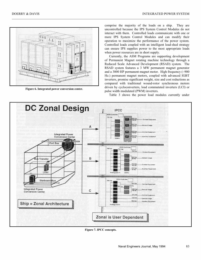
system will cause a power transient until circuit breakers isolate the fault. This disturbance can affect sensitive equipment, such as computers, throughout the ship. An IPCC, however, limits the fault current delivered to the PDM-3 (450 VAC) interface and does not appear as a fault to the PDM-2 (750 VDC) interface. In this manner, the effects of an electrical fault are isolated to a single electrical zone; and the ability of the ship to continue combat engagements despite battle damage is greatly increased. Three concepts for the IPCC are shown in Figure 7.
Figure 4. Power generation module (PGM-1)
POWER LOAD MODULES
Loads are the equipment that use electrical power to perform useful functions. For IPS, loads are categorized into three groups: Propulsion Motor Modules, uncontrolled ship service loads and controlled ship service loads. Propulsion Motor Modules consist of propulsion motors and any associated equipment and controls. Uncontrolled ship service loads
Figure 5. PGM-1 lube oil submodule
DOERRY & DAVIS INTEGRATED POWER SYSTEM
Naval Engineers Journal, May 1994 83
Figure 6. Integrated power conversion center.
comprise the majority of the loads on a ship. They are uncontrolled because the IPS System Control Modules do not interact with them. Controlled loads communicate with one or more IPS System Control Modules and can modify their operation to maximize the performance of the power system. Controlled loads coupled with an intelligent load-shed strategy can ensure IPS supplies power to the most appropriate loads when power resources are in short supply.
Currently, the ASM Programs are supporting development of Permanent Magnet rotating machine technology through a Reduced Scale Advanced Development (RSAD) system. The RSAD system features a 3 MW permanent magnet generator and a 3000 HP permanent magnet motor. High frequency (~900 Hz.) permanent magnet motors, coupled with advanced IGBT inverters, promise significant weight, size and cost reductions as compared with traditional wound-rotor synchronous motors driven by cycloconverters, load commutated inverters (LCI) or pulse width modulated (PWM) inverters.
Table 3 shows the power load modules currently under
Figure 7. IPCC concepts.
INTEGRATED POWER SYSTEM DOERRY & DAVIS
84 Naval Engineers Journal, May 1994
Table 3. Power load modules
PMM-1 PMM-2 PMM-3 PMM-4 PLM-1 PLM-2
Description ~25,000 SHP Motor
~50,000 SHP Motor
~50,000 SHP CR Motor
Aux Prop. Unit
Uncontrolled S.S. Load
Controlled S.S. Load
Pwr. Dist. Interface
PDM-1 PDM-1 PDM-1 TBD PDM-3 PDM-3
Control Interface
PCON-1 PCON-1 PCON-1 TBD None PCON-2
Rating ~20 MW ~40 MW ~40 MW TBD TBD < 3 MW
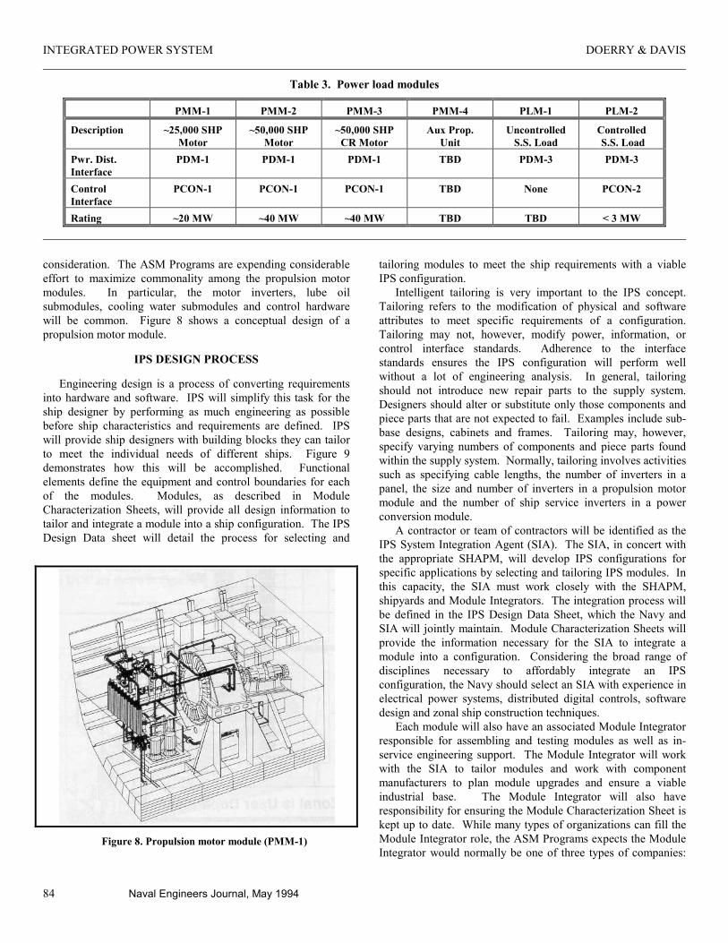
consideration. The ASM Programs are expending considerable effort to maximize commonality among the propulsion motor modules. In particular, the motor inverters, lube oil submodules, cooling water submodules and control hardware will be common. Figure 8 shows a conceptual design of a propulsion motor module.
IPS DESIGN PROCESS
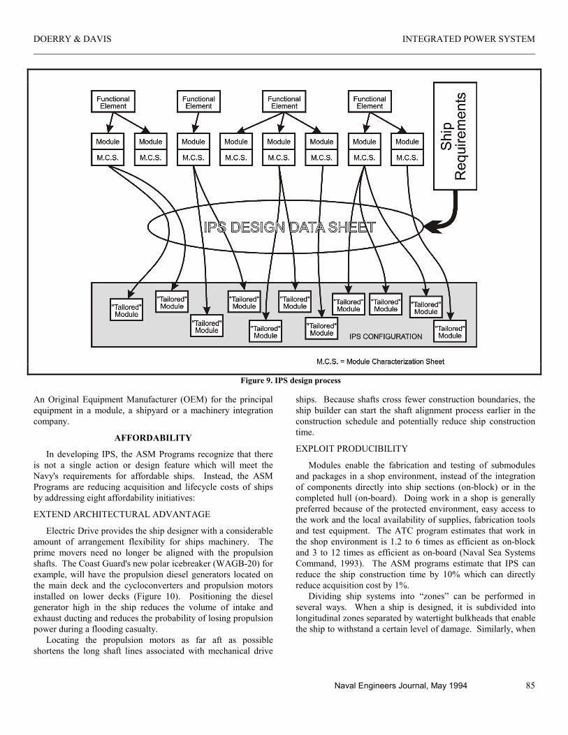
Engineering design is a process of converting requirements into hardware and software. IPS will simplify this task for the ship designer by performing as much engineering as possible before ship characteristics and requirements are defined. IPS will provide ship designers with building blocks they can tailor to meet the individual needs of different ships. Figure 9 demonstrates how this will be accomplished. Functional elements define the equipment and control boundaries for each of the modules. Modules, as described in Module Characterization Sheets, will provide all design information to tailor and integrate a module into a ship configuration. The IPS Design Data sheet will detail the process for selecting and
Figure 8. Propulsion motor module (PMM-1)
tailoring modules to meet the ship requirements with a viable IPS configuration.
Intelligent tailoring is very important to the IPS concept. Tailoring refers to the modification of physical and software attributes to meet specific requirements of a configuration. Tailoring may not, however, modify power, information, or control interface standards. Adherence to the interface standards ensures the IPS configuration will perform well without a lot of engineering analysis. In general, tailoring should not introduce new repair parts to the supply system. Designers should alter or substitute only those components and piece parts that are not expected to fail. Examples include sub-base designs, cabinets and frames. Tailoring may, however, specify varying numbers of components and piece parts found within the supply system. Normally, tailoring involves activities such as specifying cable lengths, the number of inverters in a panel, the size and number of inverters in a propulsion motor module and the number of ship service inverters in a power conversion module.
A contractor or team of contractors will be identified as the IPS System Integration Agent (SIA). The SIA, in concert with the appropriate SHAPM, will develop IPS configurations for specific applications by selecting and tailoring IPS modules. In this capacity, the SIA must work closely with the SHAPM, shipyards and Module Integrators. The integration process will be defined in the IPS Design Data Sheet, which the Navy and SIA will jointly maintain. Module Characterization Sheets will provide the information necessary for the SIA to integrate a module into a configuration. Considering the broad range of disciplines necessary to affordably integrate an IPS configuration, the Navy should select an SIA with experience in electrical power systems, distributed digital controls, software design and zonal ship construction techniques.
Each module will also have an associated Module Integrator responsible for assembling and testing modules as well as in-service engineering support. The Module Integrator will work with the SIA to tailor modules and work with component manufacturers to plan module upgrades and ensure a viable industrial base. The Module Integrator will also have responsibility for ensuring the Module Characterization Sheet is kept up to date. While many types of organizations can fill the Module Integrator role, the ASM Programs expects the Module Integrator would normally be one of three types of companies:
DOERRY & DAVIS INTEGRATED POWER SYSTEM
Naval Engineers Journal, May 1994 85
Figure 9. IPS design process
An Original Equipment Manufacturer (OEM) for the principal equipment in a module, a shipyard or a machinery integration company.
AFFORDABILITY
In developing IPS, the ASM Programs recognize that there is not a single action or design feature which will meet the Navy's requirements for affordable ships. Instead, the ASM Programs are reducing acquisition and lifecycle costs of ships by addressing eight affordability initiatives:
EXTEND ARCHITECTURAL ADVANTAGE
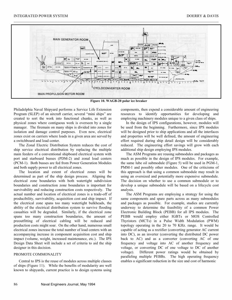
Electric Drive provides the ship designer with a considerable amount of arrangement flexibility for ships machinery. The prime movers need no longer be aligned with the propulsion shafts. The Coast Guard's new polar icebreaker (WAGB-20) for example, will have the propulsion diesel generators located on the main deck and the cycloconverters and propulsion motors installed on lower decks (Figure 10). Positioning the diesel generator high in the ship reduces the volume of intake and exhaust ducting and reduces the probability of losing propulsion power during a flooding casualty.
Locating the propulsion motors as far aft as possible shortens the long shaft lines associated with mechanical drive
ships. Because shafts cross fewer construction boundaries, the ship builder can start the shaft alignment process earlier in the construction schedule and potentially reduce ship construction time.
EXPLOIT PRODUCIBILITY
Modules enable the fabrication and testing of submodules and packages in a shop environment, instead of the integration of components directly into ship sections (on-block) or in the completed hull (on-board). Doing work in a shop is generally preferred because of the protected environment, easy access to the work and the local availability of supplies, fabrication tools and test equipment. The ATC program estimates that work in the shop environment is 1.2 to 6 times as efficient as on-block and 3 to 12 times as efficient as on-board (Naval Sea Systems Command, 1993). The ASM programs estimate that IPS can reduce the ship construction time by 10% which can directly reduce acquisition cost by 1%.
Dividing ship systems into “zones” can be performed in several ways. When a ship is designed, it is subdivided into longitudinal zones separated by watertight bulkheads that enable the ship to withstand a certain level of damage. Similarly, when
INTEGRATED POWER SYSTEM DOERRY & DAVIS
86 Naval Engineers Journal, May 1994
Figure 10. WAGB-20 polar ice breaker
Philadelphia Naval Shipyard performs a Service Life Extension Program (SLEP) of an aircraft carrier, several “mini ships” are created to sort the work into functional chunks, as well as physical zones where contiguous work is overseen by a single manager. The firemain on many ships is divided into zones for isolation and damage control purposes. Even now, electrical zones exist on carriers where loads in a given area are served by a switchboard and load center.
The Zonal Electric Distribution System reduces the cost of ship service electrical distribution by replacing the multiple main feeders of a conventional shipboard electrical system with port and starboard busses (PDM-2) and zonal load centers (PCM-1). Both busses are fed from Power Generation Modules and both supply power to all electrical zones.
The location and extent of electrical zones will be determined as part of the ship design process. Aligning the electrical zone boundaries with both watertight subdivision boundaries and construction zone boundaries is important for survivability and reducing construction costs respectively. The actual number and location of electrical zones is a trade-off of producibility, survivability, acquisition cost and ship impact. If the electrical zone spans too many watertight bulkheads, the ability of the electrical distribution system to survive flooding casualties will be degraded. Similarly, if the electrical zone spans too many construction boundaries, the amount of preoutfitting of electrical cabling will be reduced and production costs might soar. On the other hand, numerous small electrical zones increase the total number of load centers with an accompanying increase in component acquisition cost and ship impact (volume, weight, increased maintenance, etc.). The IPS Design Data Sheet will include a set of criteria to aid the ship designer in this decision.
PROMOTE COMMONALITY
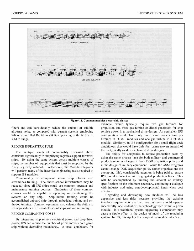
Central to IPS is the reuse of modules across multiple classes of ships (Figure 11). While the benefits of modularity are well known to shipyards, current practice is to design systems using
components, then expend a considerable amount of engineering resources to identify opportunities for developing and employing machinery modules unique to a given class of ships.
In the design of IPS configurations, however, modules will be used from the beginning. Furthermore, since IPS modules will be designed prior to ship applications and all the interfaces and properties will be well defined, the amount of engineering effort required during ship detail design will be considerably reduced. The engineering effort savings will grow with each additional ship design employing IPS modules.
The ASM Programs are reusing submodules and packages as much as possible in the design of IPS modules. For example, the same lube oil submodule (Figure 5) will be used in PGM-1, PMM-1 and possibly other modules. One of the criticisms of this approach is that using a common submodule may result in using an oversized and potentially more expensive submodule. The decision on whether to use a common submodule or to develop a unique submodule will be based on a lifecycle cost analysis.
The ASM Programs are employing a strategy for using the same components and spare parts across as many submodules and packages as possible. For example, studies are currently underway to determine the feasibility of a common Power Electronic Building Block (PEBB) for all IPS modules. The PEBB would employ either IGBTs or MOS Controlled Thyristors (MCTs) in a Pulse Width Modulation (PWM) topology operating in the 20 to 70 KHz. range. It would be capable of acting as a rectifier (converting generator AC current into DC), as an inverter (converting the distributed DC power back to AC) and as a converter (converting AC of one frequency and voltage into AC of another frequency and voltage, or converting DC of one voltage to DC of another voltage). Different power ratings would be obtained by paralleling multiple PEBBs. The high operating frequency enables a significant reduction in the size and cost of harmonic
DOERRY & DAVIS INTEGRATED POWER SYSTEM
Figure 11. Common modules across ship classes
filters and can considerably reduce the amount of audible airborne noise, as compared with current systems employing Silicon Controlled Rectifiers (SCRs) operating in the 60 Hz. to 5 KHz. range.
REDUCE INFRASTRUCTURE
The multiple levels of commonality discussed above contribute significantly to simplifying logistics support for naval ships. By using the same system across multiple classes of ships, the number of equipments that must be supported by the Navy is greatly reduced. Furthermore, the Module Integrator will perform many of the inservice engineering tasks required to support IPS modules.
Commonality of equipment across ship classes also streamlines training. The shore school infrastructure may be reduced, since all IPS ships could use common operator and maintenance training courses. Graduates of these common courses would be capable of operating or maintaining IPS systems on any ship. Ship-unique training would be accomplished onboard ship through embedded training and on-the-job training. Common equipment also enhance the ability to reassign sailors to different classes of ships without retraining..
REDUCE COMPONENT COSTS
By integrating ship service electrical power and propulsion power, IPS can reduce the number of prime movers on a given ship without degrading redundancy. A small combatant, for
example, would typically require two gas turbines for propulsion and three gas turbine or diesel generators for ship service power in a mechanical drive design. An equivalent IPS configuration would have only three prime movers: two gas turbines in PGM-1 modules and one gas turbine in a PGM-3 module. Similarly, an IPS configuration for a small flight deck amphibious ship would have only four prime movers instead of the ten typically used in mechanical drive designs.
The ability for companies to reduce production costs by using the same process lane for both military and commercial products requires changes in both DOD acquisition policy and in the design of military equipment. While the ASM Programs cannot change DOD acquisition policy (other organizations are attempting this), considerable attention is being paid to ensure IPS modules do not require segregated production lines. This will be accomplished by limiting the amount of military specifications to the minimum necessary, continuing a dialogue with industry and using non-developmental items when cost effective.
Upgrading and developing new modules will be less expensive and less risky because, providing the existing interface requirements are met, new systems should operate successfully independent of the technology used within a given module. In a traditional system, upgrading a component may cause a ripple effect in the design of much of the remaining system. In IPS, this ripple effect stops at the module interface.
INTEGRATED POWER SYSTEM DOERRY & DAVIS
88 Naval Engineers Journal, May 1994
REDUCE MANNING
IPS reduces the maintenance requirements of the ship's force by reducing the number of maintenance-intensive prime movers and by employing Equipment Health Monitoring (EHM) and Condition Based Maintenance (CBM). CBM eliminates many preventive maintenance actions by monitoring machinery parameters through EHM and only ordering maintenance when parameters indicate an impending equipment failure.
IPS offers the potential to reduce the number of condition III watchstanders by combining the functions of the Propulsion & Auxiliary Control Console (PACC) and Electrical Plant Control Console (EPCC) into a single console. In a tightly integrated plant such as IPS, it is impossible to uniquely assign many of the modules to either Propulsion or Ship Service Power. A more detailed study of watchstanding requirements for an IPS is required before this reduction in watchstanding requirements can be confirmed.
REDUCE ENERGY COSTS
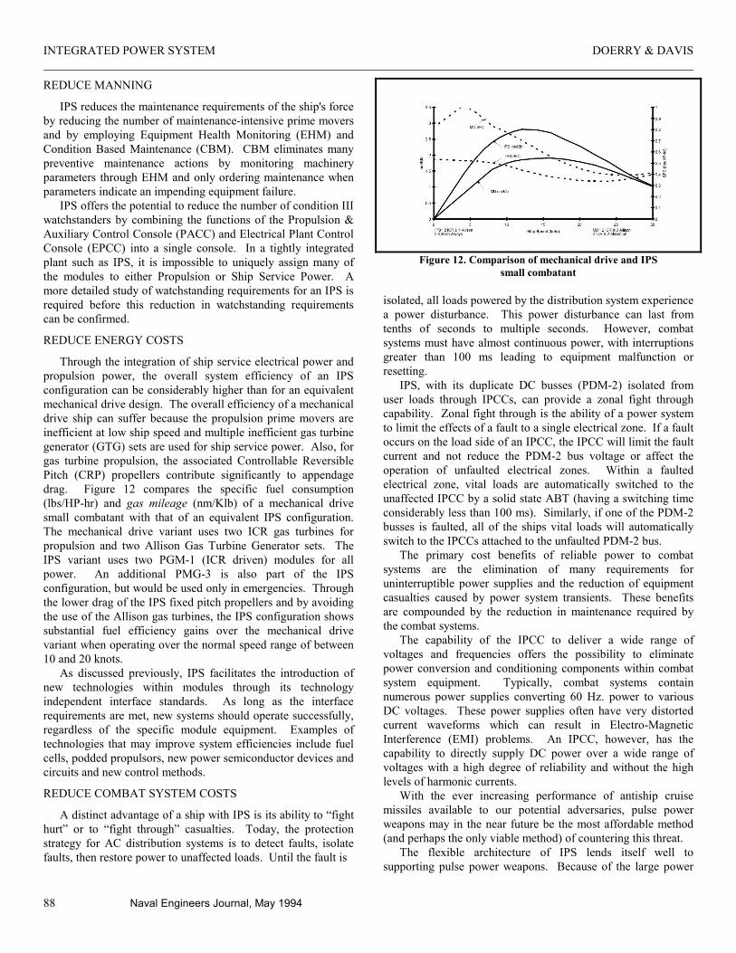
Through the integration of ship service electrical power and propulsion power, the overall system efficiency of an IPS configuration can be considerably higher than for an equivalent mechanical drive design. The overall efficiency of a mechanical drive ship can suffer because the propulsion prime movers are inefficient at low ship speed and multiple inefficient gas turbine generator (GTG) sets are used for ship service power. Also, for gas turbine propulsion, the associated Controllable Reversible Pitch (CRP) propellers contribute significantly to appendage drag. Figure 12 compares the specific fuel consumption (lbs/HP-hr) and gas mileage (nm/Klb) of a mechanical drive small combatant with that of an equivalent IPS configuration. The mechanical drive variant uses two ICR gas turbines for propulsion and two Allison Gas Turbine Generator sets. The IPS variant uses two PGM-1 (ICR driven) modules for all power. An additional PMG-3 is also part of the IPS configuration, but would be used only in emergencies. Through the lower drag of the IPS fixed pitch propellers and by avoiding the use of the Allison gas turbines, the IPS configuration shows substantial fuel efficiency gains over the mechanical drive variant when operating over the normal speed range of between 10 and 20 knots.
As discussed previously, IPS facilitates the introduction of new technologies within modules through its technology independent interface standards. As long as the interface requirements are met, new systems should operate successfully, regardless of the specific module equipment. Examples of technologies that may improve system efficiencies include fuel cells, podded propulsors, new power semiconductor devices and circuits and new control methods.
REDUCE COMBAT SYSTEM COSTS
A distinct advantage of a ship with IPS is its ability to “fight hurt” or to “fight through” casualties. Today, the protection strategy for AC distribution systems is to detect faults, isolate faults, then restore power to unaffected loads. Until the fault is
Figure 12. Comparison of mechanical drive and IPS
small combatant
isolated, all loads powered by the distribution system experience a power disturbance. This power disturbance can last from tenths of seconds to multiple seconds. However, combat systems must have almost continuous power, with interruptions greater than 100 ms leading to equipment malfunction or resetting.
IPS, with its duplicate DC busses (PDM-2) isolated from user loads through IPCCs, can provide a zonal fight through capability. Zonal fight through is the ability of a power system to limit the effects of a fault to a single electrical zone. If a fault occurs on the load side of an IPCC, the IPCC will limit the fault current and not reduce the PDM-2 bus voltage or affect the operation of unfaulted electrical zones. Within a faulted electrical zone, vital loads are automatically switched to the unaffected IPCC by a solid state ABT (having a switching time considerably less than 100 ms). Similarly, if one of the PDM-2 busses is faulted, all of the ships vital loads will automatically switch to the IPCCs attached to the unfaulted PDM-2 bus.
The primary cost benefits of reliable power to combat systems are the elimination of many requirements for uninterruptible power supplies and the reduction of equipment casualties caused by power system transients. These benefits are compounded by the reduction in maintenance required by the combat systems.
The capability of the IPCC to deliver a wide range of voltages and frequencies offers the possibility to eliminate power conversion and conditioning components within combat system equipment. Typically, combat systems contain numerous power supplies converting 60 Hz. power to various DC voltages. These power supplies often have very distorted current waveforms which can result in Electro-Magnetic Interference (EMI) problems. An IPCC, however, has the capability to directly supply DC power over a wide range of voltages with a high degree of reliability and without the high levels of harmonic currents.
With the ever increasing performance of antiship cruise missiles available to our potential adversaries, pulse power weapons may in the near future be the most affordable method (and perhaps the only viable method) of countering this threat.
The flexible architecture of IPS lends itself well to supporting pulse power weapons. Because of the large power
DOERRY & DAVIS INTEGRATED POWER SYSTEM
Naval Engineers Journal, May 1994 89
transients associated with pulse power weapons, a power management system is required to safely operate a power system providing power to propulsion or ship service loads at the same time pulse power weapons are being fired. The power management functions performed by present propulsion and ship service power controls are not capable of providing the level of power management required to service pulse power weapons. IPS, with its built in power management software (PCON-1 and PCON-2), can be extended to provide the control features necessary for pulse power weapons. Pulse power support would consist of developing a new Power Conversion Module, a new Power Distribution Module, modifications to the Power Control Modules and possibly modifications to one or more Power Generation Modules.
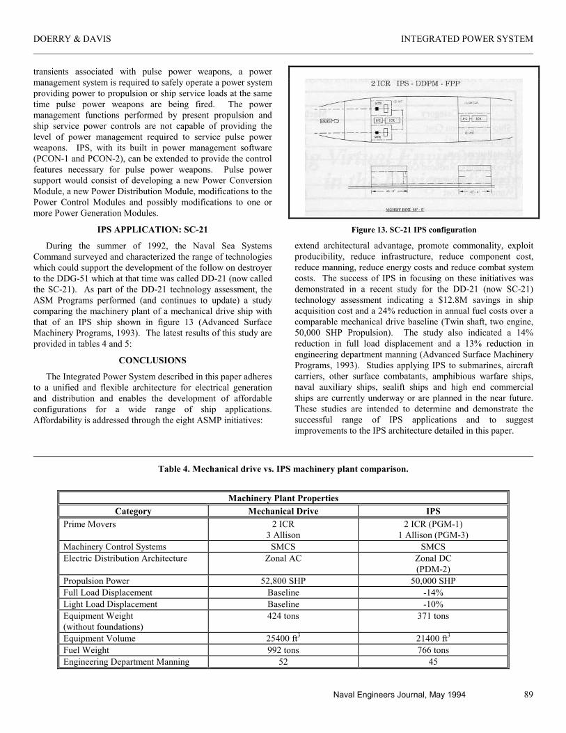
IPS APPLICATION: SC-21
During the summer of 1992, the Naval Sea Systems Command surveyed and characterized the range of technologies which could support the development of the follow on destroyer to the DDG-51 which at that time was called DD-21 (now called the SC-21). As part of the DD-21 technology assessment, the ASM Programs performed (and continues to update) a study comparing the machinery plant of a mechanical drive ship with that of an IPS ship shown in figure 13 (Advanced Surface Machinery Programs, 1993). The latest results of this study are provided in tables 4 and 5:
CONCLUSIONS
The Integrated Power System described in this paper adheres to a unified and flexible architecture for electrical generation and distribution and enables the development of affordable configurations for a wide range of ship applications. Affordability is addressed through the eight ASMP initiatives:
Figure 13. SC-21 IPS configuration
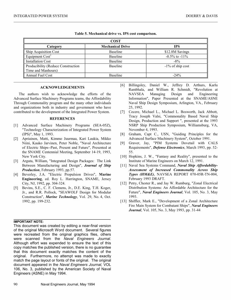
extend architectural advantage, promote commonality, exploit producibility, reduce infrastructure, reduce component cost, reduce manning, reduce energy costs and reduce combat system costs. The success of IPS in focusing on these initiatives was demonstrated in a recent study for the DD-21 (now SC-21) technology assessment indicating a $12.8M savings in ship acquisition cost and a 24% reduction in annual fuel costs over a comparable mechanical drive baseline (Twin shaft, two engine, 50,000 SHP Propulsion). The study also indicated a 14% reduction in full load displacement and a 13% reduction in engineering department manning (Advanced Surface Machinery Programs, 1993). Studies applying IPS to submarines, aircraft carriers, other surface combatants, amphibious warfare ships, naval auxiliary ships, sealift ships and high end commercial ships are currently underway or are planned in the near future. These studies are intended to determine and demonstrate the successful range of IPS applications and to suggest improvements to the IPS architecture detailed in this paper.
Table 4. Mechanical drive vs. IPS machinery plant comparison.
Machinery Plant Properties
Category Mechanical Drive IPS Prime Movers 2 ICR
3 Allison 2 ICR (PGM-1)
1 Allison (PGM-3) Machinery Control Systems SMCS SMCS Electric Distribution Architecture Zonal AC Zonal DC
(PDM-2) Propulsion Power 52,800 SHP 50,000 SHP Full Load Displacement Baseline -14% Light Load Displacement Baseline -10% Equipment Weight (without foundations)
424 tons 371 tons
Equipment Volume 25400 ft3 21400 ft3 Fuel Weight 992 tons 766 tons Engineering Department Manning 52 45
INTEGRATED POWER SYSTEM DOERRY & DAVIS
90 Naval Engineers Journal, May 1994
Table 5. Mechanical drive vs. IPS cost comparison.
COST Category Mechanical Drive IPS
Ship Acquisition Cost Baseline $12.8M Savings Equipment Cost1 Baseline -0.5% to -11% Installation Cost Baseline -8% Producibility (Reduce Construction Time and Manhours)
Baseline -1% of ship cost
Annual Fuel Cost Baseline -24%
ACKNOWLEDGEMENTS
The authors wish to acknowledge the efforts of the Advanced Surface Machinery Programs teams, the Affordability Through Commonality program and the many other individuals and organizations both in industry and government who have contributed to the development of the Integrated Power System.
REFERENCES
[1] Advanced Surface Machinery Programs (SEA-05Z), "Technology Characterization of Integrated Power System (IPS)", May 1, 1993.
[2] Apriainen, Matti, Kimmo Juurmaa, Kari Laukia, Mikko Niini, Kauko Jarvinen, Peter Noble, "Naval Architecture of Electric Ships--Past, Present and Future", Presented at the SNAME Centennial Meeting, September 14-19, 1993, New York City.
[3] Arguta, William, "Integrated Design Packages: The Link Between Manufacturing and Design", Journal of Ship Production, February 1993, pp.57.
[4] Beverley, J.A. "Electric Propulsion Drives", Marine Engineering, ed. Roy L. Harrington, SNAME, Jersey City, NJ, 1992, pp. 304-324.
[5] Bevins, S.E., C. F. Clemens, Jr., D.E. King, T.H. Koger, Jr., and R.R. Pollock, "SEAWOLF Design for Modular Construction", Marine Technology, Vol. 29, No. 4, Oct. 1992, pp. 199-232.
[6] Billingsley, Daniel W., Jeffrey D. Arthurs, Karlu Rambhala, and William R. Schmidt, "Revolution at NAVSEA Managing Design and Engineering Information", Paper Presented at the SNAME/ASNE Naval Ship Design Symposium, Arlington, VA., February 25, 1992.
[7] Cecere, Michael L., Michael L. Bosworth, Jack Abbott, Tracy Joseph Valsi, "Commonality Based Naval Ship Design, Production and Support ", presented at the 1993 NSRP Ship Production Symposium, Williamsburg, VA, November 4, 1993.
[8] Graham, Capt C., USN, "Guiding Principles for the Advanced Surface Machinery System", October 1991.
[9] Graver, Jay, "PIM Systems Dovetail with CALS Requirements", Defense Electronics, March 1993, pp. 52-55.
[10] Hopkins, J. W., "Fantasy and Reality", presented to the Institute of Marine Engineers on March 12, 1991.
[11] Naval Sea Systems Command, Naval Ship Affordability-Assessment of Increased Commonality Across Ship Types (HM&E), NAVSEA REPORT 070-05R-TN-004, February 1993 DRAFT.
[12] Petry, Chester R., and Jay W. Rumburg, "Zonal Electrical Distribution Systems: An Affordable Architecture for the Future", Naval Engineers Journal, Vol. 105, No. 3, May 1993.
[13] Shiffler, Mark E., "Development of a Zonal Architecture Fire Main System for Combatant Ships", Naval Engineers Journal, Vol. 105, No. 3, May 1993, pp. 31-44
IMPORTANT NOTE: This document was created by editing a near-final version of the original Microsoft Word document. Several figures were recreated from the original graphics files, others were scanned from the Naval Engineers Journal. Although effort was expended to ensure the text of this copy matches the published version, there is no guarantee that this document exactly matches the content of the original. Furthermore, no attempt was made to exactly match the page layout or fonts of the original. The original document appeared in the Naval Engineers Journal, VOL 106, No. 3, published by the American Society of Naval Engineers (ASNE) in May 1994.