Embed Size (px)
Citation preview
Integrated Risk Management
EMIS 7303

Admin Stuff Instructor: Jan Lyons, PhD Email: [email protected]
Warning – have to select from LM address book
Email is preferred contact option Phone: 972-603-9319
Office hours: after class and by appointment
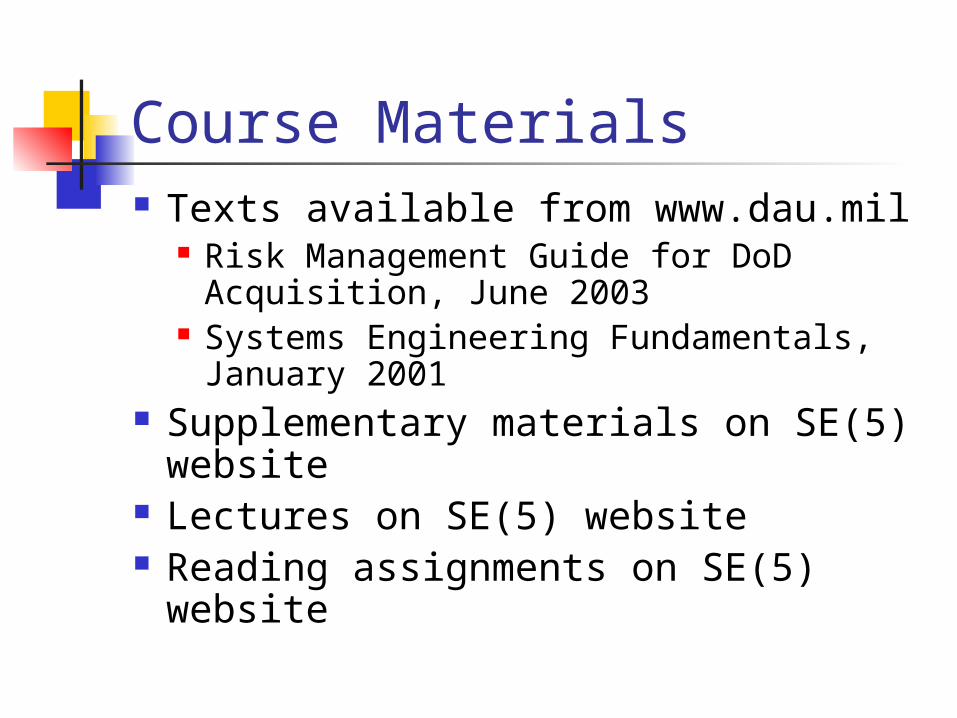
Course Materials Texts available from www.dau.mil
Risk Management Guide for DoD Acquisition, June 2003
Systems Engineering Fundamentals, January 2001
Supplementary materials on SE(5) website
Lectures on SE(5) website Reading assignments on SE(5)
website
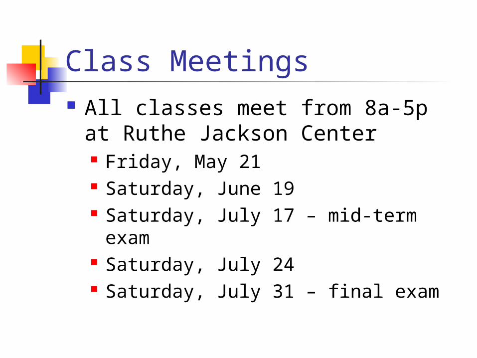
Class Meetings All classes meet from 8a-5p at
Ruthe Jackson Center Friday, May 21 Saturday, June 19 Saturday, July 17 – mid-term exam Saturday, July 24 Saturday, July 31 – final exam
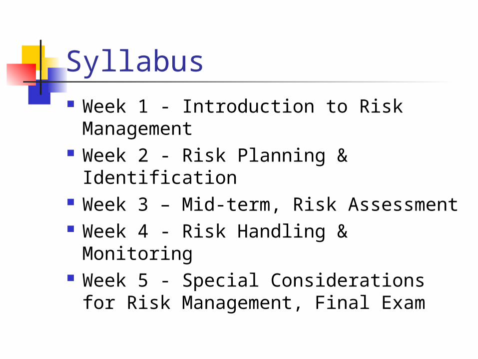
Syllabus Week 1 - Introduction to Risk
Management Week 2 - Risk Planning & Identification Week 3 – Mid-term, Risk Assessment Week 4 - Risk Handling & Monitoring Week 5 - Special Considerations for
Risk Management, Final Exam
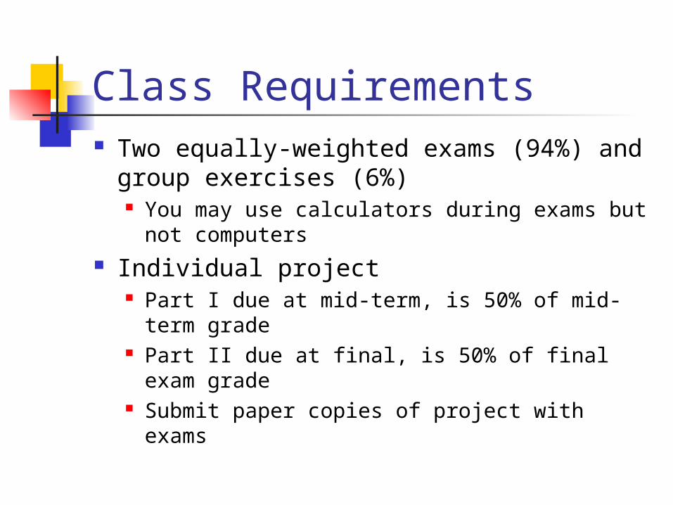
Class Requirements Two equally-weighted exams (94%) and
group exercises (6%) You may use calculators during exams but
not computers Individual project
Part I due at mid-term, is 50% of mid-term grade
Part II due at final, is 50% of final exam grade
Submit paper copies of project with exams
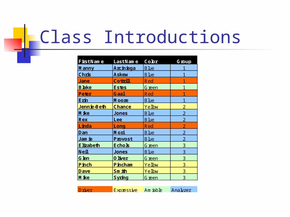
Class IntroductionsFirst Name Last Name Color GroupManny Arciniega Blue 1Chris Askew Blue 1Jane Cottrill Red 1Blake Estes Green 1Peter Gaal Red 1Erin Moore Blue 1Jennie-Beth Chance Yellow 2Mike Jones Blue 2Rex Lee Blue 2Linda Long Red 2Dan Mori Blue 2Jamie Provost Blue 2Elizabeth Echols Green 3Neil Jones Blue 3Glen Oliver Green 3Pinch Pincham Yellow 3Dave Smith Yellow 3Mike Syring Green 3
Driver Expressive Amiable Analyzer
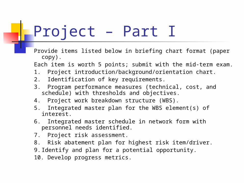
Project – Part IProvide items listed below in briefing chart format (paper copy).Each item is worth 5 points; submit with the mid-term exam.1. Project introduction/background/orientation chart. 2. Identification of key requirements. 3. Program performance measures (technical, cost, and
schedule) with thresholds and objectives. 4. Project work breakdown structure (WBS). 5. Integrated master plan for the WBS element(s) of interest. 6. Integrated master schedule in network form with personnel
needs identified. 7. Project risk assessment. 8. Risk abatement plan for highest risk item/driver. 9. Identify and plan for a potential opportunity.10. Develop progress metrics.
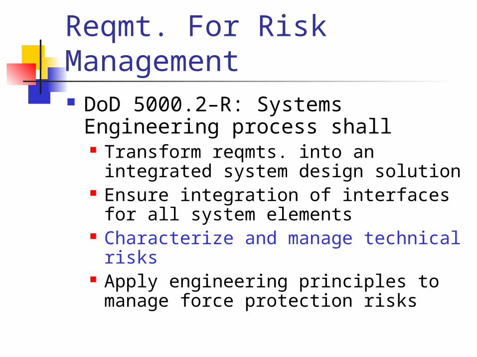
Reqmt. For Risk Management DoD 5000.2–R: Systems
Engineering process shall Transform reqmts. into an integrated
system design solution Ensure integration of interfaces for all
system elements Characterize and manage technical
risks Apply engineering principles to
manage force protection risks
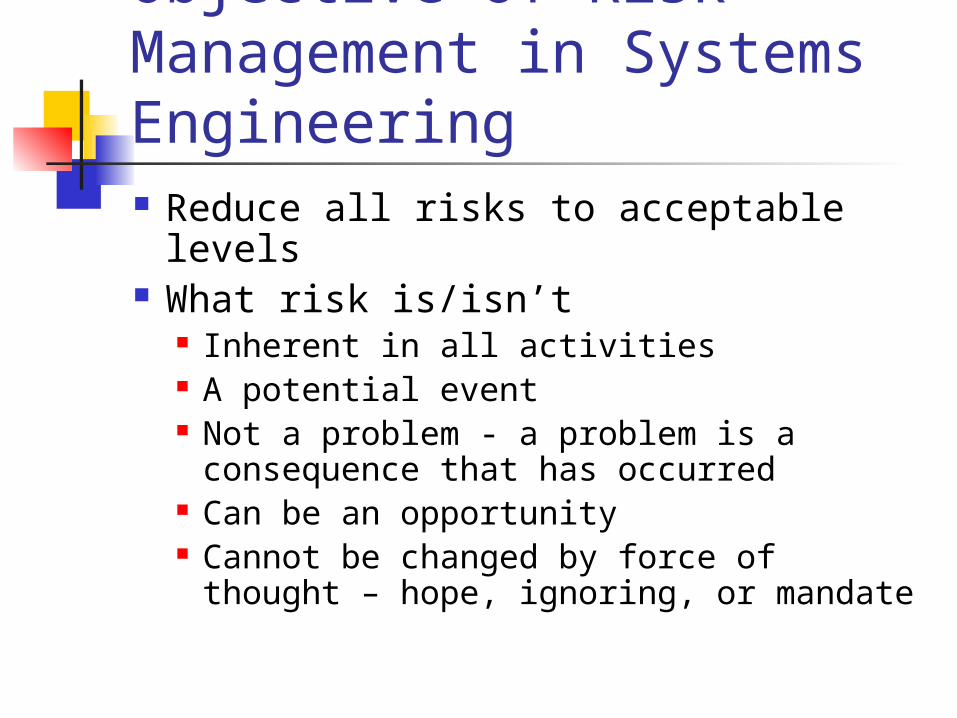
Objective of Risk Management in Systems Engineering Reduce all risks to acceptable levels What risk is/isn’t
Inherent in all activities A potential event Not a problem - a problem is a
consequence that has occurred Can be an opportunity Cannot be changed by force of thought
– hope, ignoring, or mandate
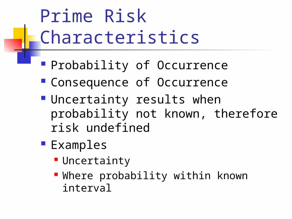
Prime Risk Characteristics Probability of Occurrence Consequence of Occurrence Uncertainty results when probability
not known, therefore risk undefined Examples
Uncertainty Where probability within known interval
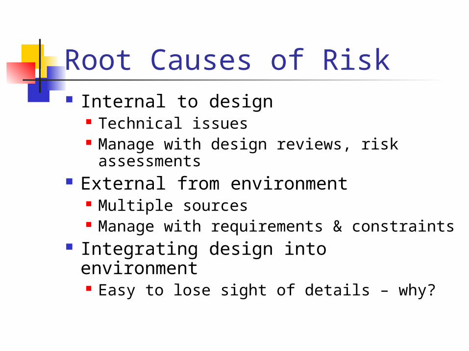
Root Causes of Risk Internal to design
Technical issues Manage with design reviews, risk
assessments External from environment
Multiple sources Manage with requirements &
constraints Integrating design into environment
Easy to lose sight of details – why?
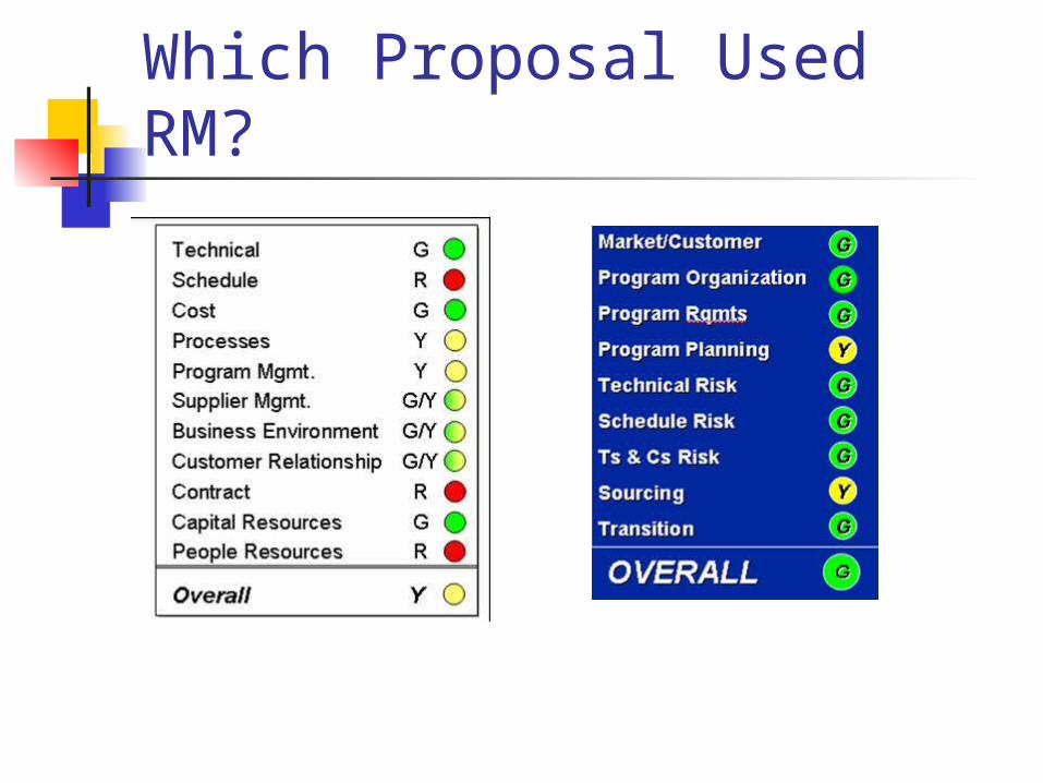
Which Proposal Used RM?
How the SE Process Supports Risk Management
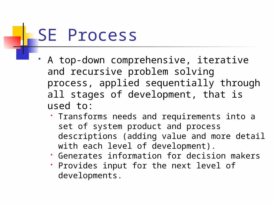
SE Process A top-down comprehensive, iterative
and recursive problem solving process, applied sequentially through all stages of development, that is used to: Transforms needs and requirements into a
set of system product and process descriptions (adding value and more detail with each level of development).
Generates information for decision makers Provides input for the next level of
developments.
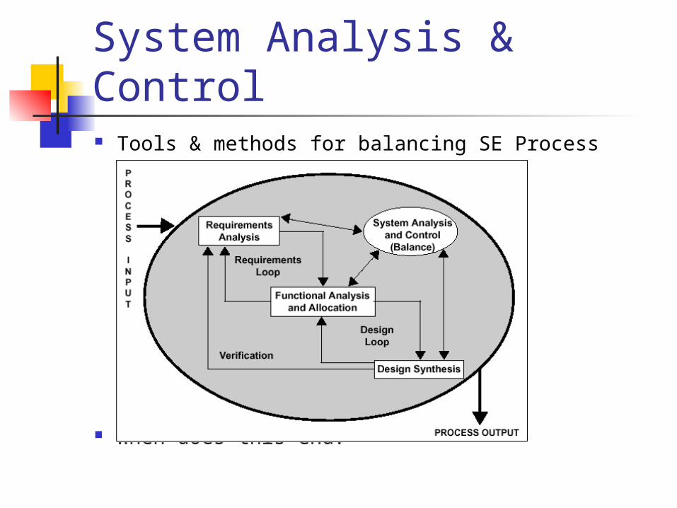
System Analysis & Control Tools & methods for balancing SE Process
When does this end?
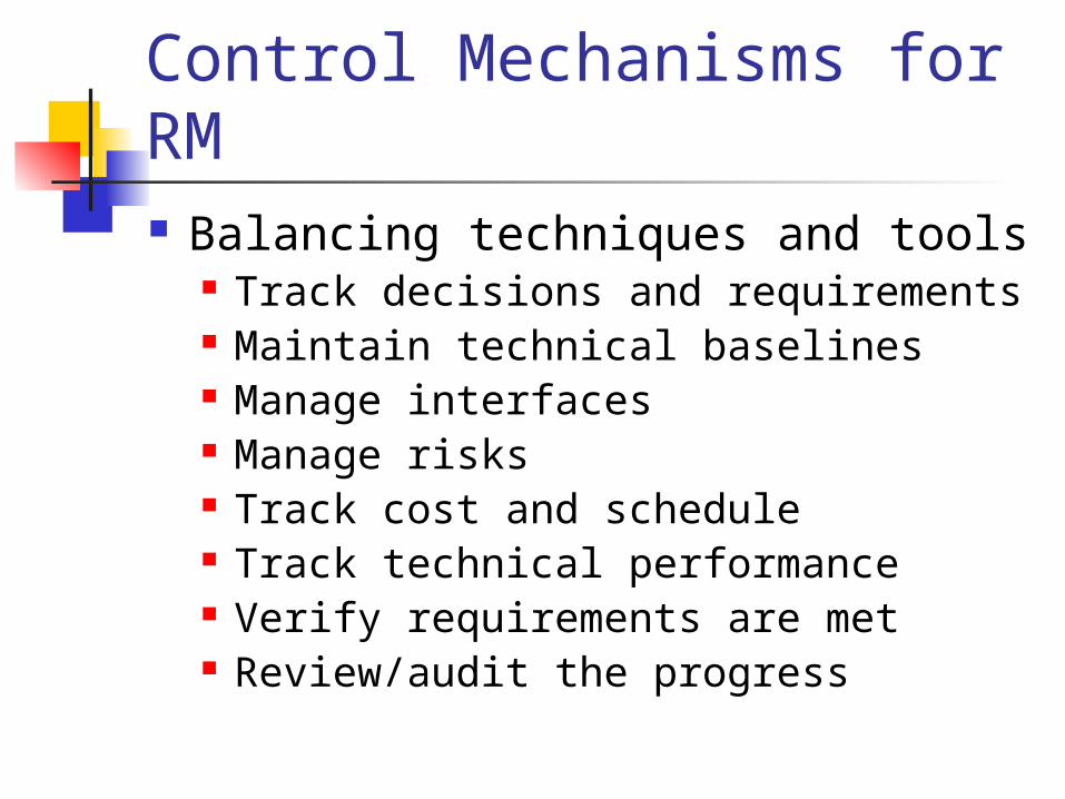
Control Mechanisms for RM Balancing techniques and tools
Track decisions and requirements Maintain technical baselines Manage interfaces Manage risks Track cost and schedule Track technical performance Verify requirements are met Review/audit the progress
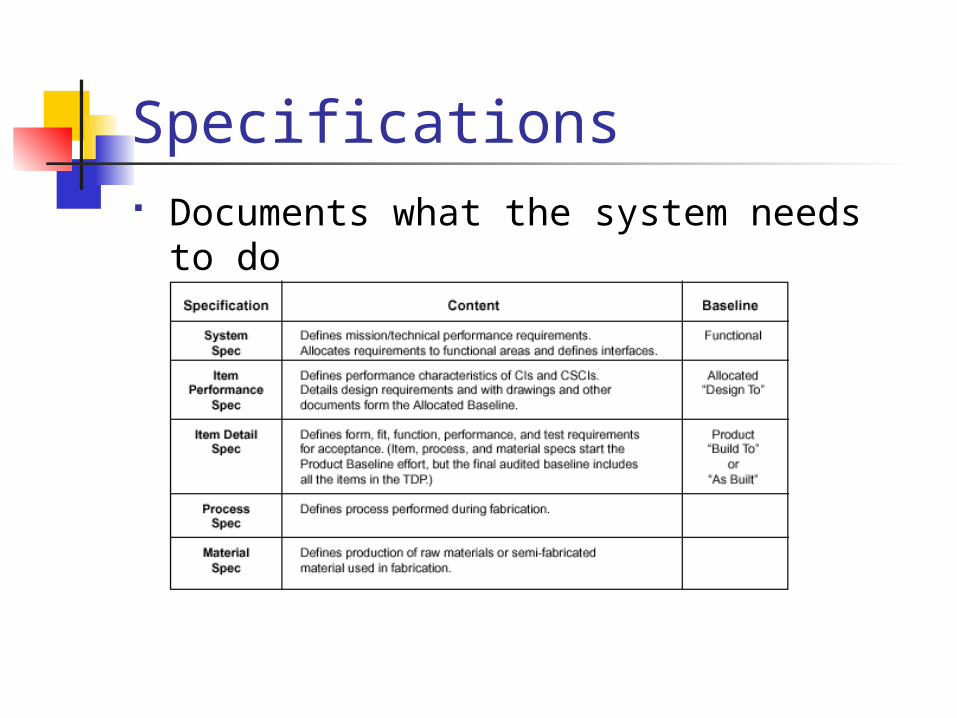
Specifications Documents what the system needs to
do

Performance Requirements Detail why the system is needed Three parts
Function Performance level Verification means
How do good requirements help identify probabilities and consequences?
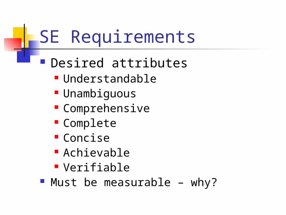
SE Requirements Desired attributes
Understandable Unambiguous Comprehensive Complete Concise Achievable Verifiable
Must be measurable – why?
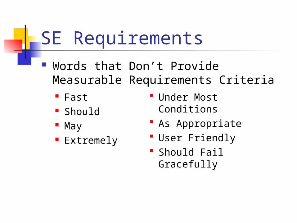
SE Requirements Words that Don’t Provide Measurable
Requirements Criteria Fast Should May Extremely
Under Most Conditions As Appropriate User Friendly Should Fail Gracefully
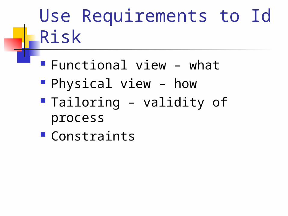
Use Requirements to Id Risk Functional view – what Physical view – how Tailoring – validity of process Constraints
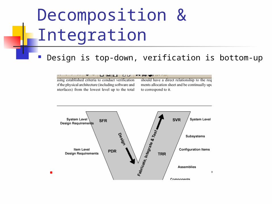
Decomposition & Integration Design is top-down, verification is bottom-up
How helps/hurts in risk identification?
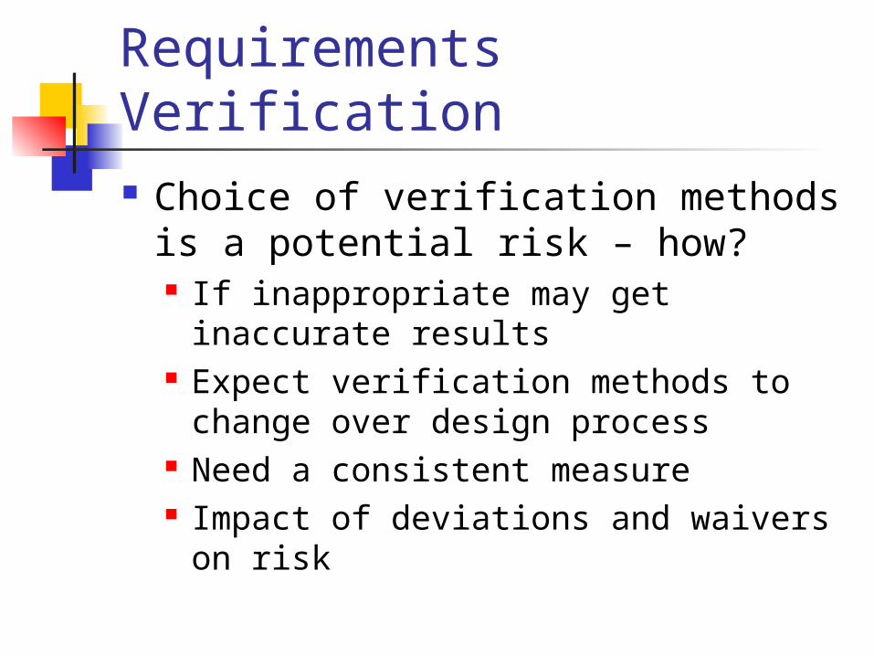
Requirements Verification Choice of verification methods is a
potential risk – how? If inappropriate may get inaccurate
results Expect verification methods to
change over design process Need a consistent measure Impact of deviations and waivers on
risk
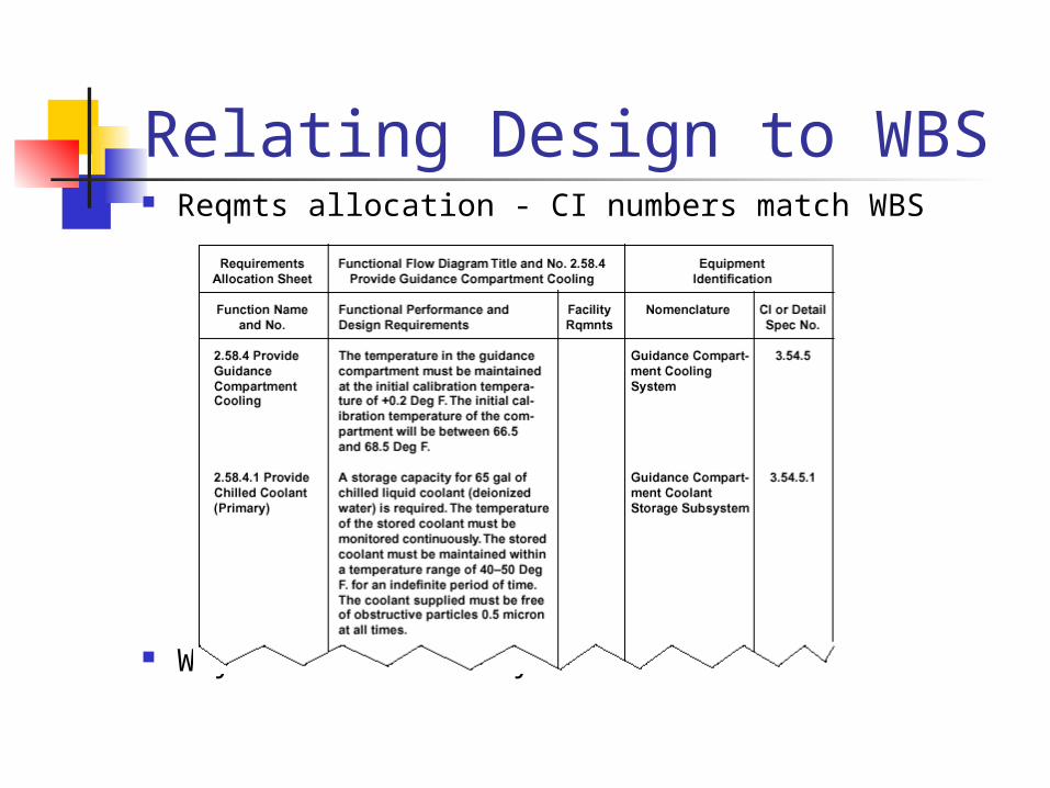
Relating Design to WBS Reqmts allocation - CI numbers match WBS
Why assess risks by WBS?
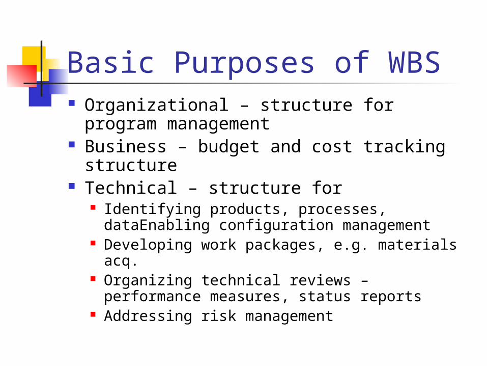
Basic Purposes of WBS Organizational – structure for program
management Business – budget and cost tracking
structure Technical – structure for
Identifying products, processes, dataEnabling configuration management
Developing work packages, e.g. materials acq. Organizing technical reviews – performance
measures, status reports Addressing risk management
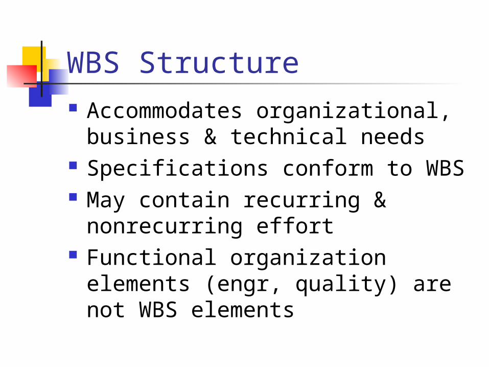
WBS Structure Accommodates organizational,
business & technical needs Specifications conform to WBS May contain recurring &
nonrecurring effort Functional organization elements
(engr, quality) are not WBS elements
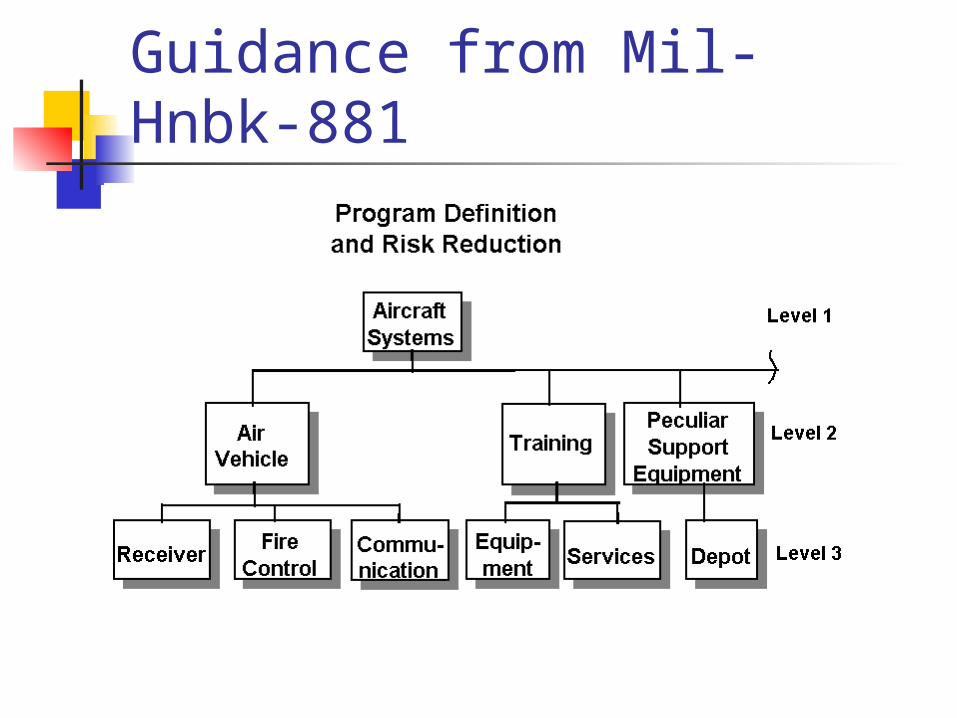
Guidance from Mil-Hnbk-881
WBS Exercise
Background: You have recently been assigned to the IPD Team for the Peace Whey program. Peace Whey is a recently approved FMS program which will provide 20 F-16Cs to the Kurdish Air Force (KAF). The specifications for the Kurdish F-16s call for them to be equipped with the Airborne Jamming System (AJS), an electronic warfare system. Your position will be as AJS team leader responsible for the oversight of design and testing of the AJS system, for its integration into the Peace Whey aircraft, and for the AJS lab and flight testing verification. In addition, you must act as the interface between the AJS team and the other teams making up the IPD Team for the Peace Whey program, making certain that the program office is supported in its overall coordination and management tasks.
WBS Exercise (con’t)
Exercise: Referring to the Statement of Customer Requirements for AJS (Part 1) which you have been provided, develop a Work Breakdown Structure (WBS) for the AJS development and production
task as a part of the overall air vehicle development task.
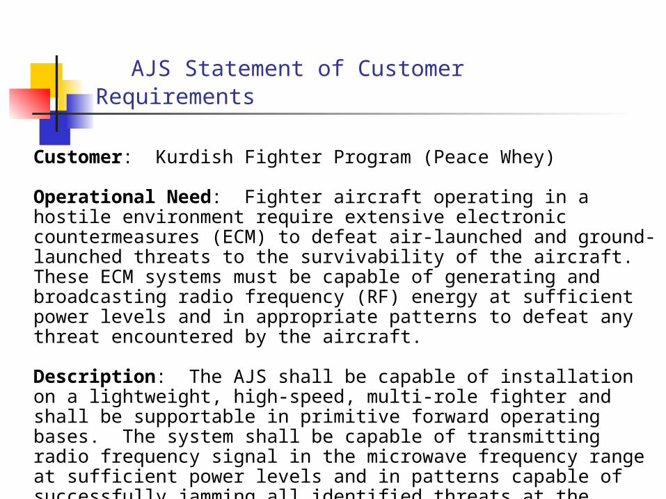
AJS Statement of Customer Requirements
Customer: Kurdish Fighter Program (Peace Whey)
Operational Need: Fighter aircraft operating in a hostile environment require extensive electronic countermeasures (ECM) to defeat air-launched and ground-launched threats to the survivability of the aircraft. These ECM systems must be capable of generating and broadcasting radio frequency (RF) energy at sufficient power levels and in appropriate patterns to defeat any threat encountered by the aircraft.
Description: The AJS shall be capable of installation on a lightweight, high-speed, multi-role fighter and shall be supportable in primitive forward operating bases. The system shall be capable of transmitting radio frequency signal in the microwave frequency range at sufficient power levels and in patterns capable of successfully jamming all identified threats at the required operational range.
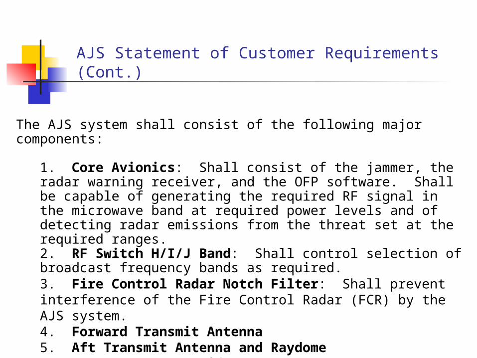
AJS Statement of Customer Requirements (Cont.)
The AJS system shall consist of the following major components:
1. Core Avionics: Shall consist of the jammer, the radar warning receiver, and the OFP software. Shall be capable of generating the required RF signal in the microwave band at required power levels and of detecting radar emissions from the threat set at the required ranges. 2. RF Switch H/I/J Band: Shall control selection of broadcast frequency bands as required.3. Fire Control Radar Notch Filter: Shall prevent interference of the Fire Control Radar (FCR) by the AJS system.4. Forward Transmit Antenna5. Aft Transmit Antenna and Raydome6. WRD-650D24 Waveguide7. Coaxial Cable
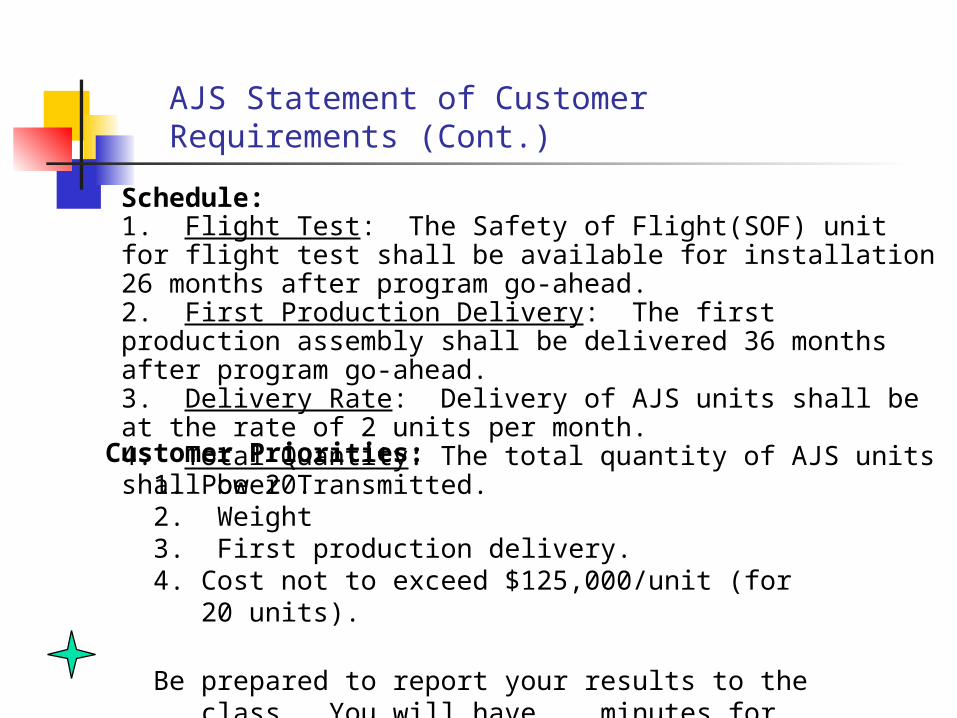
Schedule:1. Flight Test: The Safety of Flight(SOF) unit for flight test shall be available for installation 26 months after program go-ahead.2. First Production Delivery: The first production assembly shall be delivered 36 months after program go-ahead.3. Delivery Rate: Delivery of AJS units shall be at the rate of 2 units per month.4. Total Quantity: The total quantity of AJS units shall be 20.
AJS Statement of Customer Requirements (Cont.)
Customer Priorities:1. Power Transmitted.2. Weight3. First production delivery.4. Cost not to exceed $125,000/unit (for 20 units).
Be prepared to report your results to the class. You will have __ minutes for this exercise.
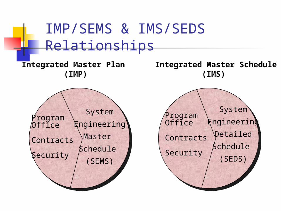
IMP/SEMS & IMS/SEDS Relationships
Integrated Master Plan (IMP)
Integrated Master Schedule(IMS)
ProgramOffice
Contracts
Security
System
Engineering
Master
Schedule
(SEMS)
ProgramOffice
Contracts
Security
System
Engineering
Detailed
Schedule
(SEDS)
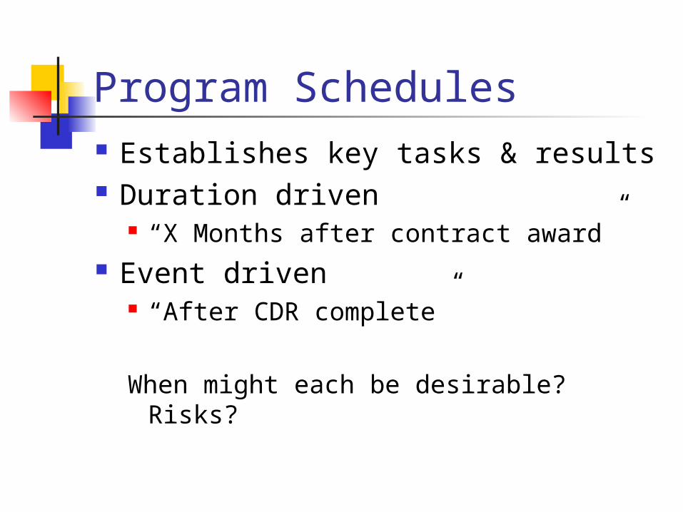
Program Schedules Establishes key tasks & results Duration driven
“X Months after contract award” Event driven
“After CDR complete” When might each be desirable? Risks?
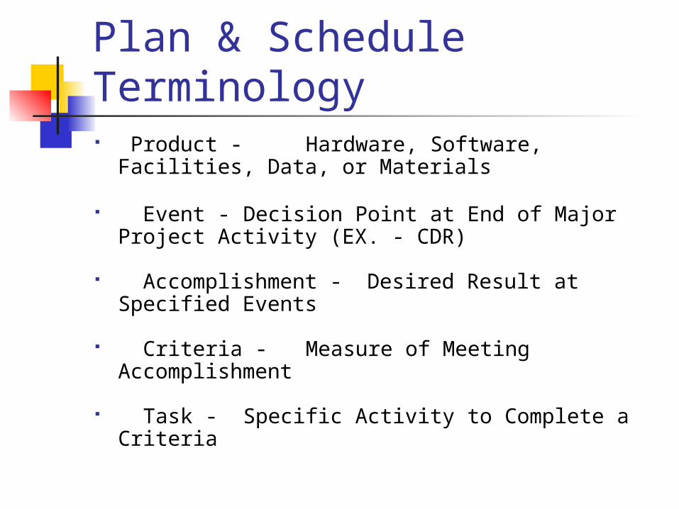
Plan & Schedule Terminology Product - Hardware, Software, Facilities, Data,
or Materials
Event - Decision Point at End of Major Project Activity (EX. - CDR)
Accomplishment - Desired Result at Specified Events
Criteria - Measure of Meeting Accomplishment
Task - Specific Activity to Complete a Criteria
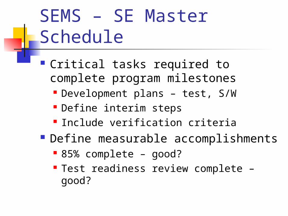
SEMS – SE Master Schedule Critical tasks required to complete
program milestones Development plans – test, S/W Define interim steps Include verification criteria
Define measurable accomplishments 85% complete – good? Test readiness review complete – good?
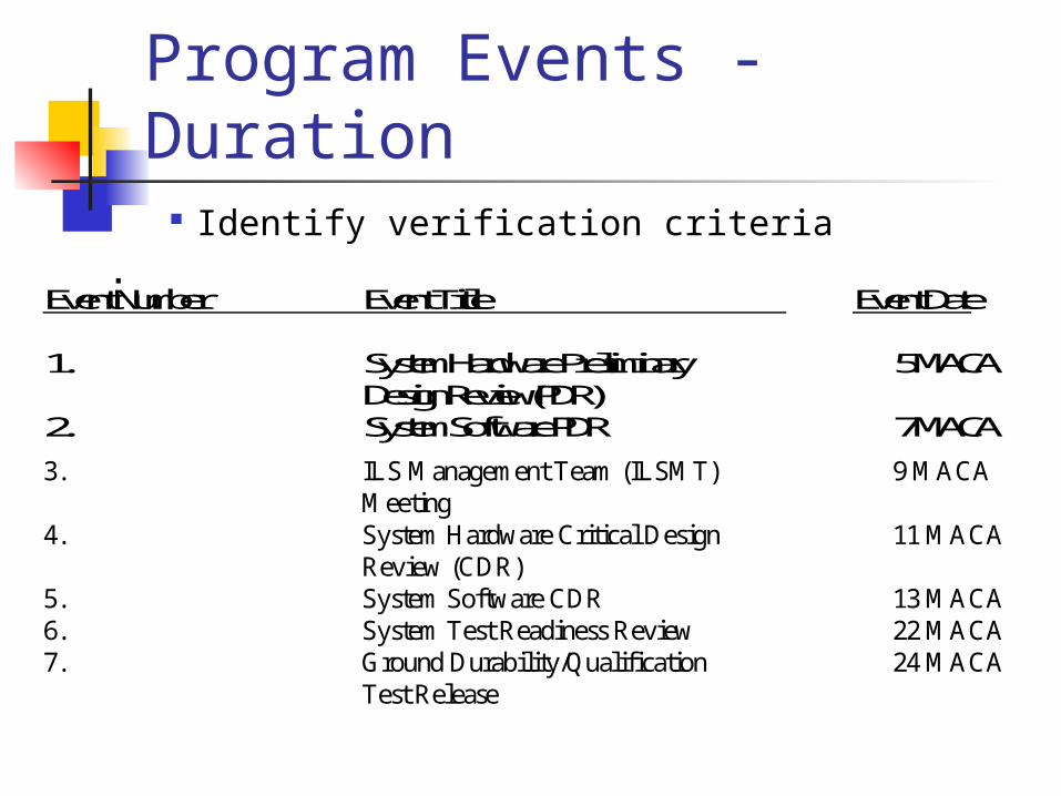
Program Events - Duration3.0 SEMS PROGRAM EVENTS
Listed below are the Major Program Events and their scheduled time of achievement. Each event shall be considered achieved upon successful demonstrationof criteria accomplishments. Criteria for each event is defined in Section 4.0.Event Number Event Title Event Date
1. System Hardware Preliminary 5 MACADesign Review(PDR)
2. System Software PDR 7 MACA
3. ILS Management Team (ILSMT) 9 MACAMeeting
4. System Hardware Critical Design 11 MACAReview (CDR)
5. System Software CDR 13 MACA6. System Test Readiness Review 22 MACA7. Ground Durability/Qualification 24 MACA
Test Release
Identify verification criteria
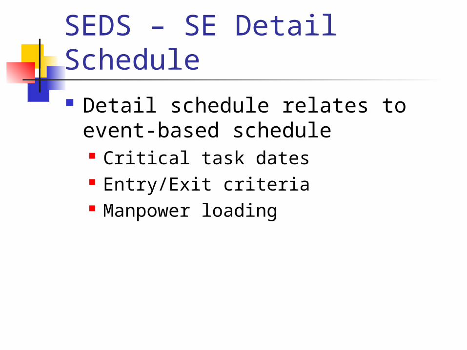
SEDS – SE Detail Schedule Detail schedule relates to event-
based schedule Critical task dates Entry/Exit criteria Manpower loading
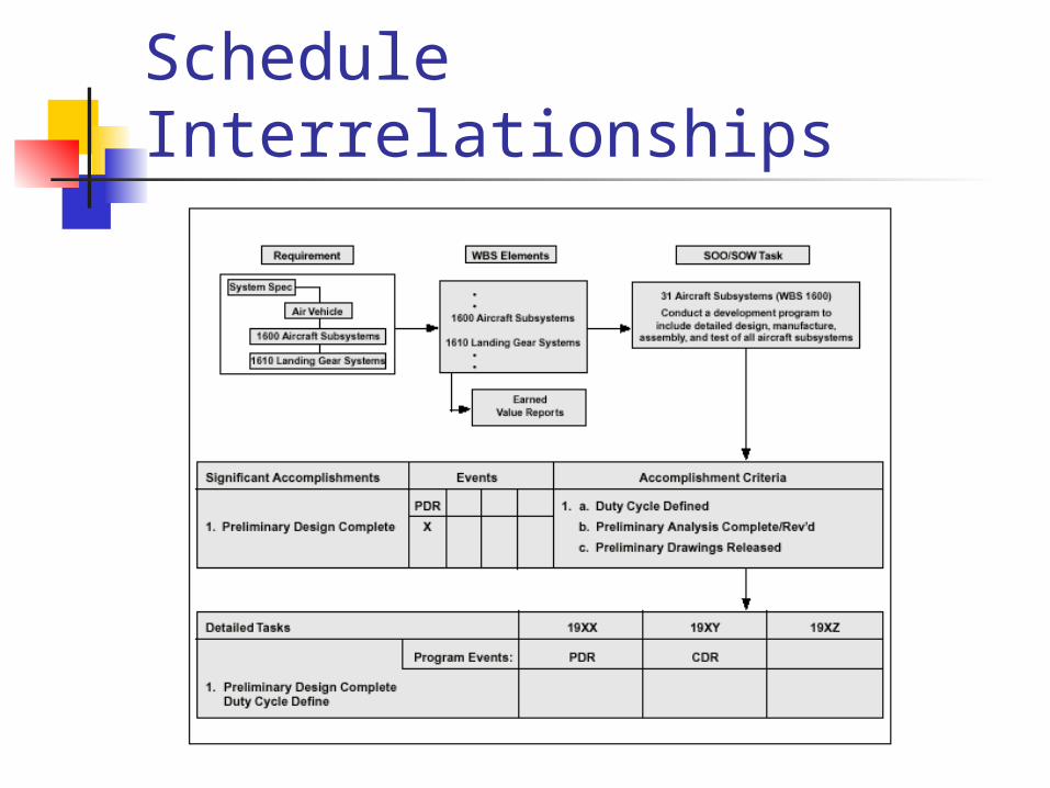
Schedule Interrelationships
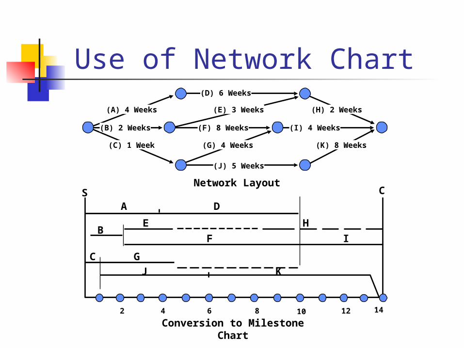
Network Layout
Conversion to Milestone Chart
K
2 4 6 8 10 12 14
J
C G
A D
BE H
F I
S C
(D) 6 Weeks
(A) 4 Weeks (E) 3 Weeks
(I) 4 Weeks
(H) 2 Weeks
(C) 1 Week (G) 4 Weeks
(J) 5 Weeks
(B) 2 Weeks (F) 8 Weeks
(K) 8 Weeks
Use of Network Chart
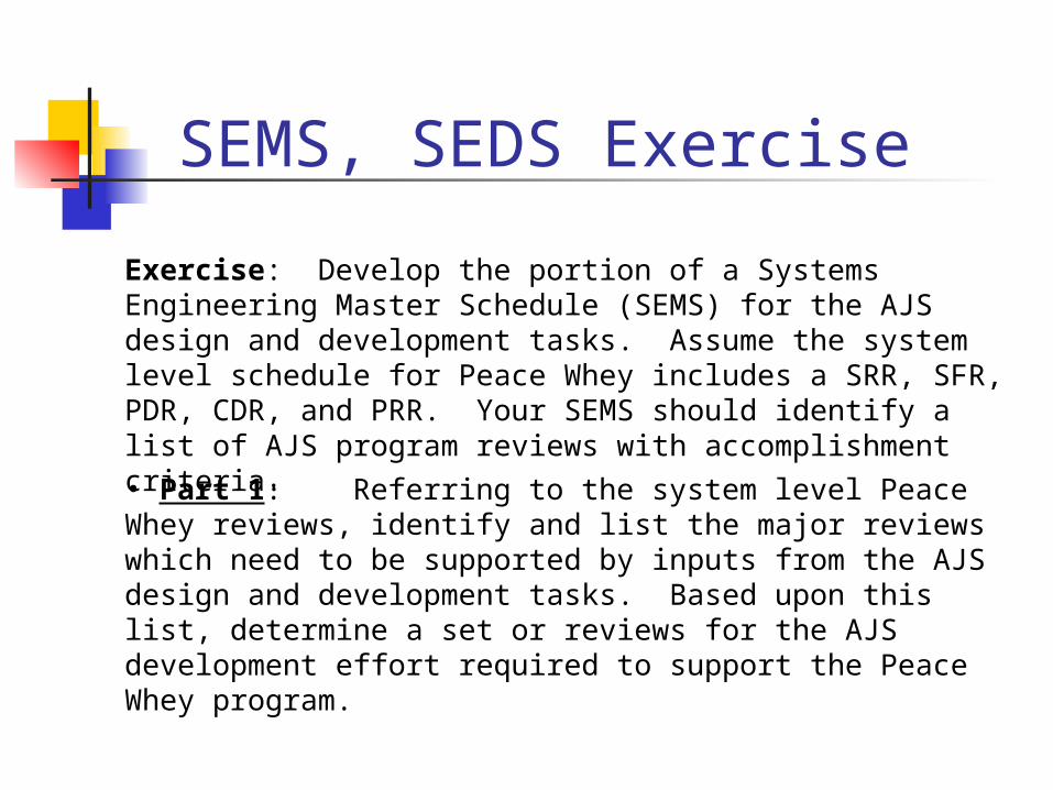
SEMS, SEDS Exercise
Exercise: Develop the portion of a Systems Engineering Master Schedule (SEMS) for the AJS design and development tasks. Assume the system level schedule for Peace Whey includes a SRR, SFR, PDR, CDR, and PRR. Your SEMS should identify a list of AJS program reviews with accomplishment criteria.
• Part 1: Referring to the system level Peace Whey reviews, identify and list the major reviews which need to be supported by inputs from the AJS design and development tasks. Based upon this list, determine a set or reviews for the AJS development effort required to support the Peace Whey program.

SEMS, SEDS Exercise (con’t)
• Part 2: Identify the accomplishment criteria for one AJS review.
• Part 3: Develop a System Engineering Detailed Schedule (SEDS) for the AJS design and development task. The AJS Safety of Flight unit must be available in month 26 and first production aircraft in month 36. Hint – Use building block tasks on next page.
Be prepared to report your results to the class. You will have 40 minutes for this exercise.
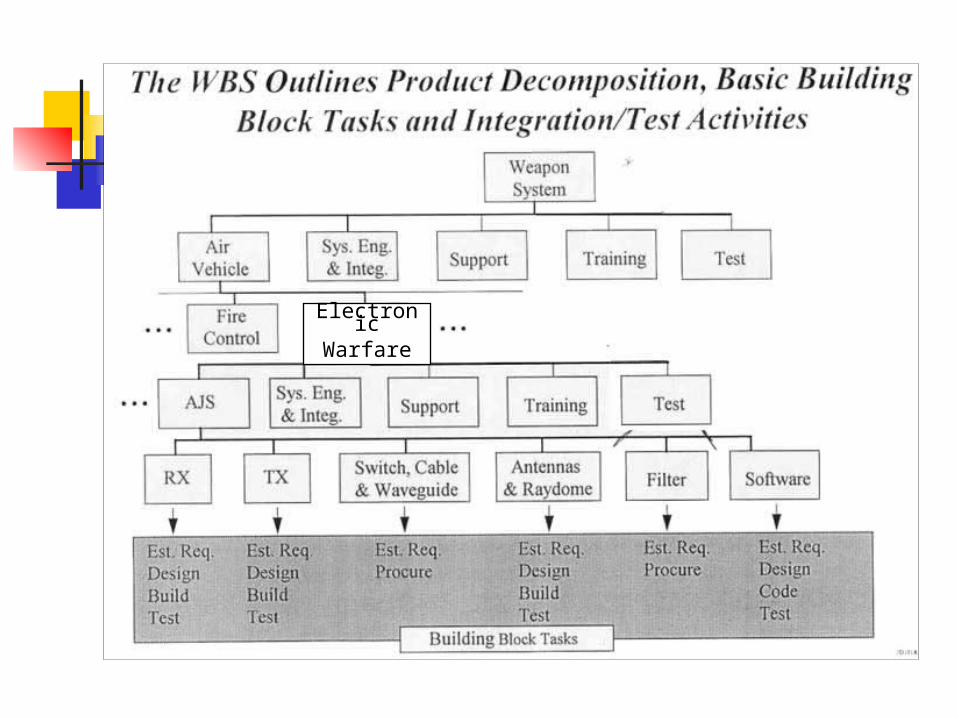
ElectronicWarfare
Next Week: Risk Planning & Identification
Read: Remainder of SE FundamentalsRisk Management Guide through section 5.3