Embed Size (px)
Citation preview
INTEGRATED SMART HYDRAULIC DISPLACEMENT MACHINE FOR CLOSED SYSTEMS
Werner Döhla1, Jörg Bauer1, Rocco Kemnitz1
1RAPA Automotive GmbH&Co. KG
ABSTRACT
The following article describes the development, validation and series introduction of a novel highly
integrated smart electrohydraulic 4-quadrant displacement machine. Starting in 2012, an unique unit
consisting of a hydraulic internal gear machine combined with a newly developed electric machine
with integrated electronic unit was created. The developed unit aims at the application in fully active
automotive chassis in combination with hydraulic shock absorbers. The very special requirements of
this application resulted in a new development with numerous detailed solutions which are described
below. Parallel and interacting with the product development, all new series assembly and testing
devices tailored to this product was developed.
Keywords: Fully active chassis, smart hydraulics, integrated electronics, Motor-Pump-Unit
1. OBJECTIVE
The task of the project was to develop an electro-
hydraulic displacement machine for fully active
chassis systems. The focus was on fully active
chassis systems which combine the hydraulic
shock absorber with an associated hydraulic
displacement machine in the basic conceptual
approach. In order to be independent of the drive
concept of the vehicle, an electro-hydraulic unit
had to be implemented. Through the combination
with a hydraulic shock absorber, the electro-
hydraulic displacement machine becomes part of
a closed and permanently pre-pressurized system.
This resulted in system-related special functional
requirements for the unit which had to be taken
into account in the development. In addition to
dynamic aspects, the machine have to be also
have sufficient compressive strength.
2. TECHNICAL CONCEPT
The result of the detailed concept considerations
for the given task was the use of an integrated
design consisting of hydraulic displacer and
electric machine in the form of an integrated
design. Specifically in the form of an under oil
running electric machine with direct hydraulic
connection to the displacer. With this design, no
sealing of the drive shaft to the atmosphere is
necessary, an aspect which was given high
priority, since such a seal has various
disadvantages. In addition to the entry of
mechanical friction as a result of the sealing and
risks to the compliance with the sealing
requirements over the entire operating range and
the service life, the sealing, due to the permanent
pressurization of the closed system, also poses
requirements that can hardly be met with
currently known sealing systems. On the other
hand, the electrical machine have to have the
appropriate pressure resistance, a challenge
whose solution is described in more detail in
section 3.1.
3. COMPONENTS
3.1. Electrical motor
A comparison of different types and designs of
electric motors showed the use of a permanently
excited synchronous machine as the most
appropriate solution. In addition to its basic
suitability for a wet-running machine, the very
compact design is an argument in favour of using
such a design due to the high power density of the
machine. To define the basic design of the
permanently excited synchronous machine,
numerous designs were compared with each
other by means of simulation analyses. Basically,
the use of a so-called 12/10 design was identified
as a very suitable topology. This involves 12
stator teeth which are combined with a 10-pole
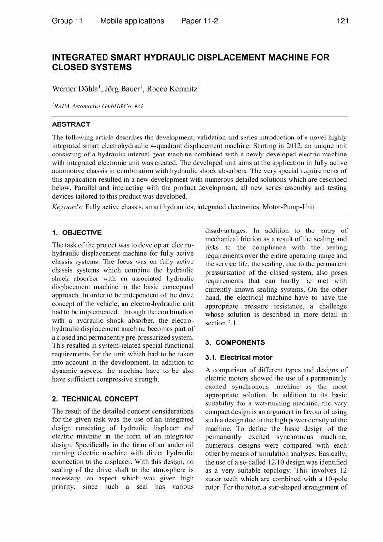
rotor. For the rotor, a star-shaped arrangement of
the 10 permanent magnet stacks within the
lamination stack has proven to be the most
advantageous solution. The selected rotor design
is shown in figure 1.
Figure 1: Rotor design
The cuboid permanent magnets are inserted into
the correspondingly shaped openings in the sheet
metal packet. Radially, the permanent magnets
are held positively by the laminated core. In order
to fix the magnets axially, the laminated core
equipped with the permanent magnets is
overmoulded with a thermoplastic material. The
plastic overmoulding is also used to make the
rotor easy to balance. For this purpose, a type of
plastic disc with numerous mounting holes
evenly distributed around the circumference is
injection moulded onto both axial ends of the
laminated core. Balancing elements in the form
of metal balls are pressed into the cylindrical
openings during the balancing process. This
method of additive balancing is, in addition to the
simple design, also ideally suited to ensure that,
in contrast to negative balancing forms, no
contamination is left behind in the production
process. The greatest challenge in the
development of the electrical machine was to find
a suitable design form that combines the
necessary compressive strength on the one hand
with the requirement for a compact design and
high efficiency on the other. Concepts with a
completely hydraulically flooded motor, i.e.
flooding of the stator space as well, were rejected
because the surrounding housing was too large
and heavy for this case. Since this variant was not
the solution, an other solution had to be
developed which would provide a hydraulically
pressure-resistant seal between stator and rotor.
There are known solutions for this task in the
form of so-called can which are arranged in the
magnetic working air gap between stator and
rotor. For the pressures occurring in the specific
application, the market provides metallic cans.
However, the electrical eddy currents occurring
in the metallic can reduce the efficiency of the
electric machine. Such a decrease was not
acceptable under the given objectives regarding
the efficiency. The only way out is to use a
canned tube made of an electrically non-
conductive material. With regard to an
automotive series application and the associated
restrictive cost structure of the individual parts, a
solution made of glass fibre reinforced
thermoplastic material is aimed for.
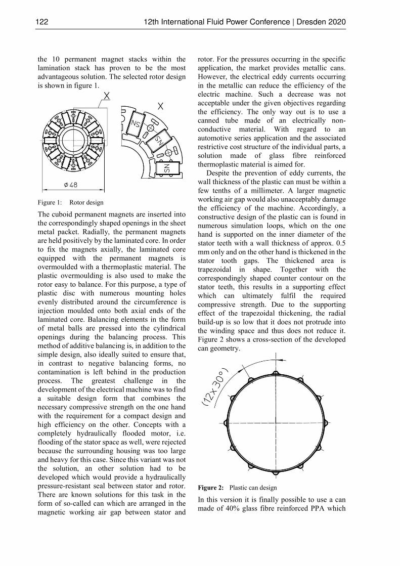
Despite the prevention of eddy currents, the
wall thickness of the plastic can must be within a
few tenths of a millimeter. A larger magnetic
working air gap would also unacceptably damage
the efficiency of the machine. Accordingly, a
constructive design of the plastic can is found in
numerous simulation loops, which on the one
hand is supported on the inner diameter of the
stator teeth with a wall thickness of approx. 0.5
mm only and on the other hand is thickened in the
stator tooth gaps. The thickened area is
trapezoidal in shape. Together with the
correspondingly shaped counter contour on the
stator teeth, this results in a supporting effect
which can ultimately fulfil the required
compressive strength. Due to the supporting
effect of the trapezoidal thickening, the radial
build-up is so low that it does not protrude into
the winding space and thus does not reduce it.
Figure 2 shows a cross-section of the developed
can geometry.
Figure 2: Plastic can design
In this version it is finally possible to use a can
made of 40% glass fibre reinforced PPA which
can withstand operating pressures up to 150 bar
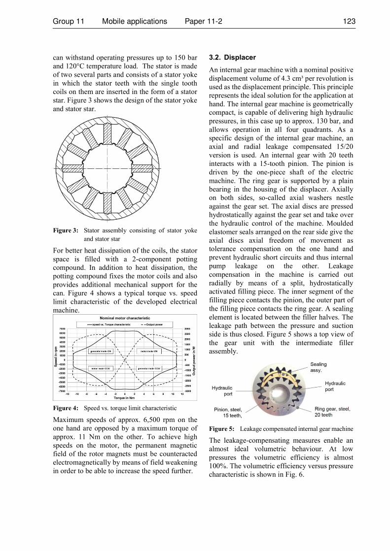
and 120°C temperature load. The stator is made
of two several parts and consists of a stator yoke
in which the stator teeth with the single tooth
coils on them are inserted in the form of a stator
star. Figure 3 shows the design of the stator yoke
and stator star.
Figure 3: Stator assembly consisting of stator yoke
and stator star
For better heat dissipation of the coils, the stator
space is filled with a 2-component potting
compound. In addition to heat dissipation, the
potting compound fixes the motor coils and also
provides additional mechanical support for the
can. Figure 4 shows a typical torque vs. speed
limit characteristic of the developed electrical
machine.
Figure 4: Speed vs. torque limit characteristic
Maximum speeds of approx. 6,500 rpm on the
one hand are opposed by a maximum torque of
approx. 11 Nm on the other. To achieve high
speeds on the motor, the permanent magnetic
field of the rotor magnets must be counteracted
electromagnetically by means of field weakening
in order to be able to increase the speed further.
3.2. Displacer
An internal gear machine with a nominal positive
displacement volume of 4.3 cm³ per revolution is
used as the displacement principle. This principle
represents the ideal solution for the application at
hand. The internal gear machine is geometrically
compact, is capable of delivering high hydraulic
pressures, in this case up to approx. 130 bar, and
allows operation in all four quadrants. As a
specific design of the internal gear machine, an
axial and radial leakage compensated 15/20
version is used. An internal gear with 20 teeth
interacts with a 15-tooth pinion. The pinion is
driven by the one-piece shaft of the electric
machine. The ring gear is supported by a plain
bearing in the housing of the displacer. Axially
on both sides, so-called axial washers nestle
against the gear set. The axial discs are pressed
hydrostatically against the gear set and take over
the hydraulic control of the machine. Moulded
elastomer seals arranged on the rear side give the
axial discs axial freedom of movement as
tolerance compensation on the one hand and
prevent hydraulic short circuits and thus internal
pump leakage on the other. Leakage
compensation in the machine is carried out
radially by means of a split, hydrostatically
activated filling piece. The inner segment of the
filling piece contacts the pinion, the outer part of
the filling piece contacts the ring gear. A sealing
element is located between the filler halves. The
leakage path between the pressure and suction
side is thus closed. Figure 5 shows a top view of
the gear unit with the intermediate filler
assembly.
Figure 5: Leakage compensated internal gear machine
The leakage-compensating measures enable an
almost ideal volumetric behaviour. At low
pressures the volumetric efficiency is almost
100%. The volumetric efficiency versus pressure
characteristic is shown in Fig. 6.

Figure 6: Typical volumetric efficiency vs. pressure
and torque vs. pressure curve
The high volumetric efficiency allows a very
good response of the machine in reverse
operation, an important function in the present
application where the machine constantly
changes its operating point across all four
quadrants. The internal gear machine described
here is based on a solution that already exists on
the market. The challenge with this component
was, on the one hand, the automotive
industrialization of the machine originating from
the industrial sector and, on the other hand, the
necessary optimization of the noise behavior.
Although the principle used in industrial
applications appeared inconspicuous,
considerable detail optimizations were necessary
to reduce the pressure pulsation introduced into
the downstream system and to reduce the radiated
airborne noise. No less challenging is setting up
and validation of the series supply chain for the
demanding individual parts of the displacer unit.
3.3. Electronics
The electronics unit to drive the electric machine
is flanged directly and radially to the bottom of
the motor housing on the side facing away from
the displacer machine. The motor housing is used
as a thermal sink for cooling the power
semiconductors. A permanent magnet located at
the end of the motor shaft facing the electronics
serves as a position sensor for a Hall sensor on
the electronics to detect the actual position of the
rotor. The housing is thin-walled between the
permanent magnet as rotor position sensor and
the Hall sensor. The thin wall seals off the
hydraulic area from the electronics on the one
hand and still allows the Hall sensor to detect the
permanent magnetic field sufficiently. The
integrated electronics have all the contents for
controlling the electric machine and thus make
the machine a smart unit. Besides the power
supply, which is designed for 48V, the default
signals and status variables are exchanged via a
CAN bus connection. Speed or torque can be
selected as target values for the motor controller.
Various actual values of the machine are
available as status information on the CAN
connection. It is especially worth mentioning that
measured actual pressures are also made
available at the two hydraulic connections of the
machine. The measured pressure values are
determined via two miniature pressure sensors
integrated in the hydraulic machine. The two
sensors are integrated in the housing of the
hydraulic machine, not visible from the outside,
and are electrically connected to the electronic
unit via a contact assembly through the motor. In
addition to measuring pressure, the two sensors
also record the temperature at the installation
location. In addition to the functional concerns,
the electronic unit fulfils an ASIL classification
according to Level C for selected features that
have been agreed with the customer.
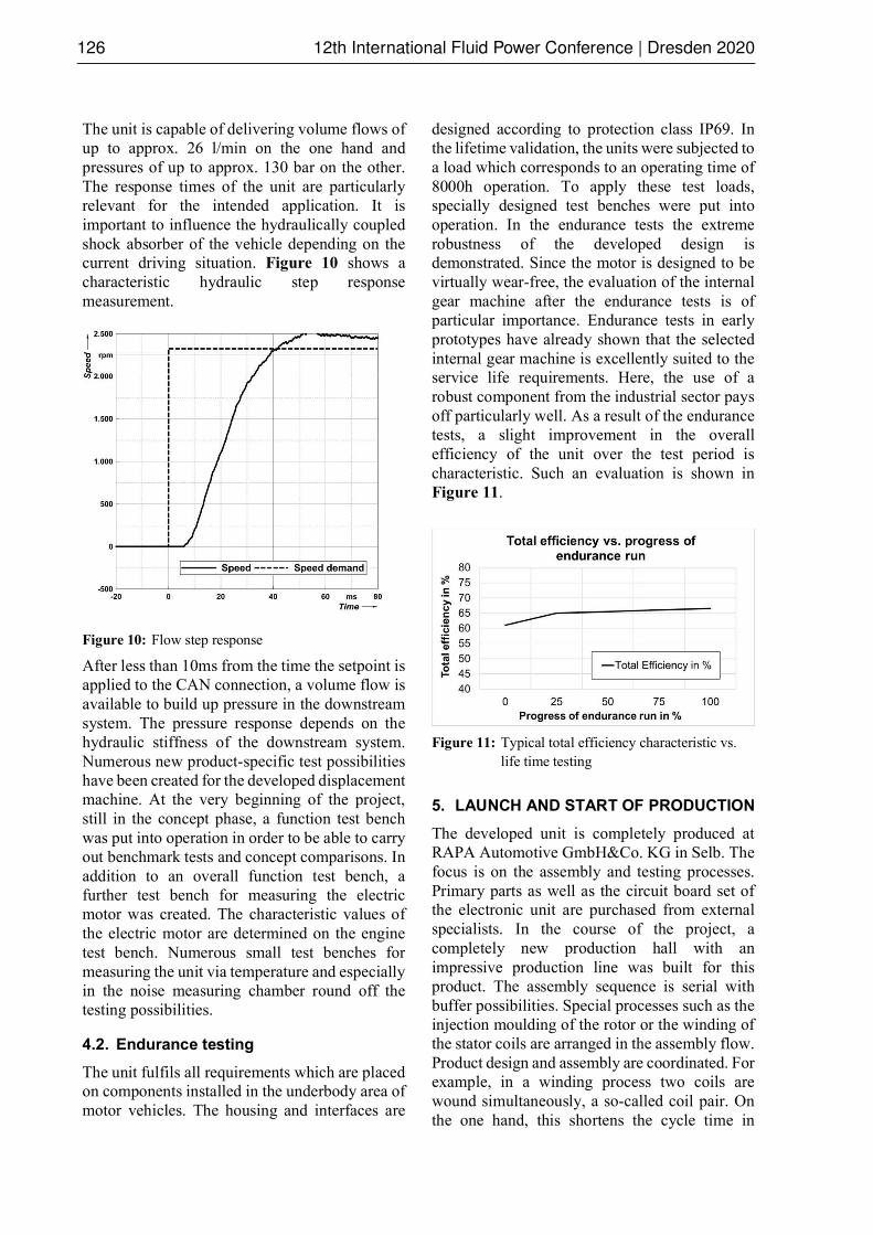
Mechanically, the electronic unit consists of two
printed circuit boards, the power board attached
directly to the motor housing and a signal board.
Both printed circuit boards are mechanically and
electrically connected to each other via an
intermediate assembly. The intermediate
assembly is a plastic carrier part in which the
geometrically large and heavy electronic
components of the electrical intermediate circuit
and the input filter are mechanically fixed. In
addition, contact bridges are arranged in the part
for the electrical connection of the two boards
adjacent to the front sides of the intermediate
assembly. The intermediate assembly and the two
circuit boards form a stacked structure which is
screwed to the bottom of the motor housing. The
three electrical motor phase connections pass
through the bottom of the motor housing and the
power board and are screwed to the power board
with contact elements. The developed electronic
unit can provide electrical string currents of up to
120Arms. Figure 7 shows the developed machine
without electronics housing.
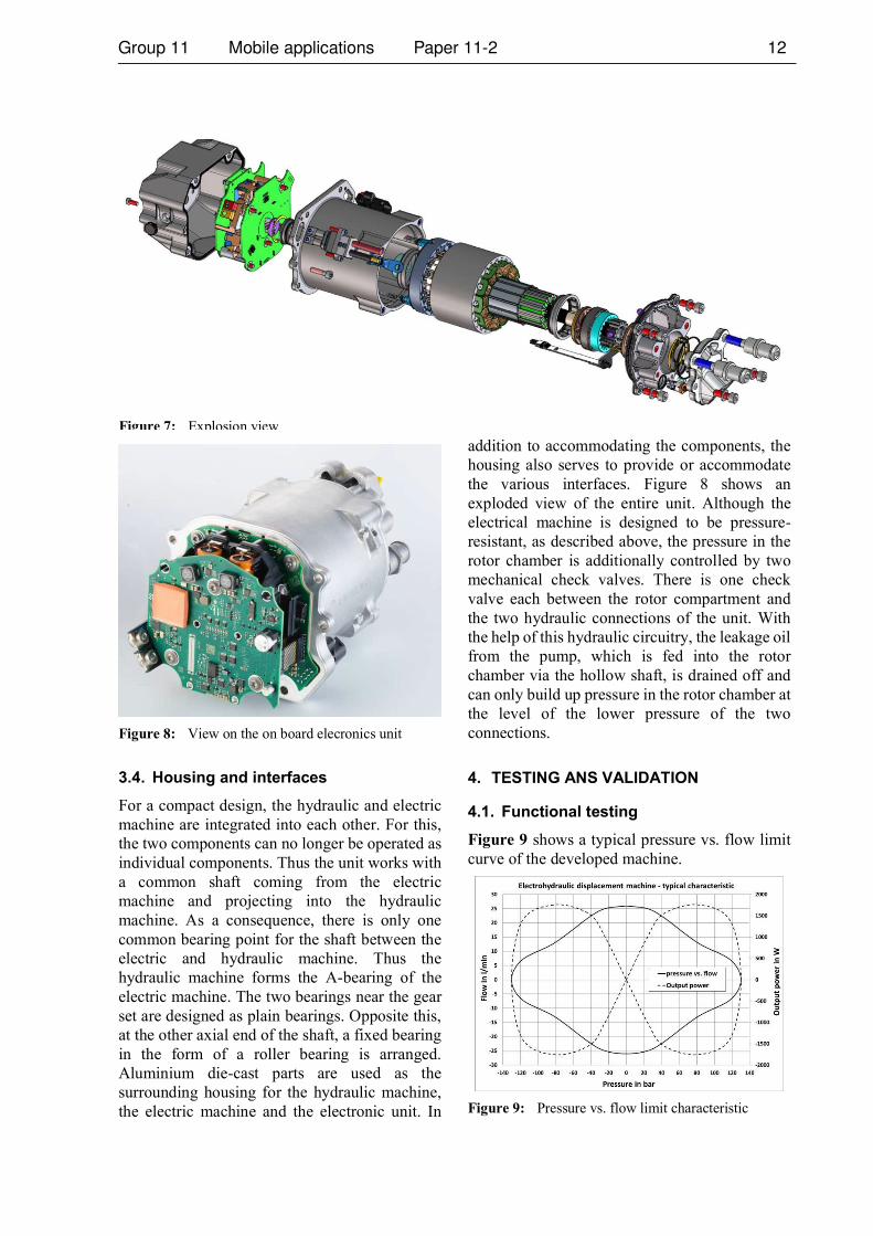
Figure 8: View on the on board elecronics unit
3.4. Housing and interfaces
For a compact design, the hydraulic and electric
machine are integrated into each other. For this,
the two components can no longer be operated as
individual components. Thus the unit works with
a common shaft coming from the electric
machine and projecting into the hydraulic
machine. As a consequence, there is only one
common bearing point for the shaft between the
electric and hydraulic machine. Thus the
hydraulic machine forms the A-bearing of the
electric machine. The two bearings near the gear
set are designed as plain bearings. Opposite this,
at the other axial end of the shaft, a fixed bearing
in the form of a roller bearing is arranged.
Aluminium die-cast parts are used as the
surrounding housing for the hydraulic machine,
the electric machine and the electronic unit. In
addition to accommodating the components, the
housing also serves to provide or accommodate
the various interfaces. Figure 8 shows an
exploded view of the entire unit. Although the
electrical machine is designed to be pressure-
resistant, as described above, the pressure in the
rotor chamber is additionally controlled by two
mechanical check valves. There is one check
valve each between the rotor compartment and
the two hydraulic connections of the unit. With
the help of this hydraulic circuitry, the leakage oil
from the pump, which is fed into the rotor
chamber via the hollow shaft, is drained off and
can only build up pressure in the rotor chamber at
the level of the lower pressure of the two
connections.
4. TESTING ANS VALIDATION
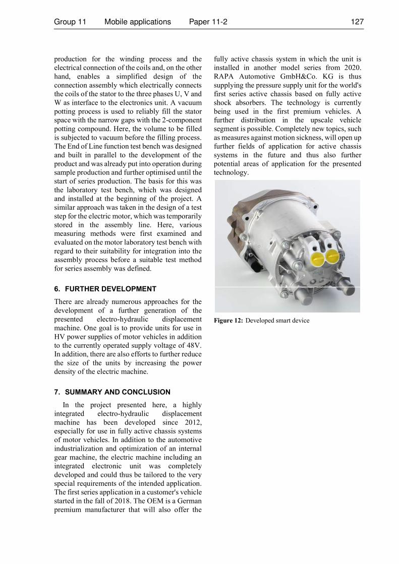
4.1. Functional testing
Figure 9 shows a typical pressure vs. flow limit
curve of the developed machine.
Figure 9: Pressure vs. flow limit characteristic
Figure 7: Explosion view
The unit is capable of delivering volume flows of
up to approx. 26 l/min on the one hand and
pressures of up to approx. 130 bar on the other.
The response times of the unit are particularly
relevant for the intended application. It is
important to influence the hydraulically coupled
shock absorber of the vehicle depending on the
current driving situation. Figure 10 shows a
characteristic hydraulic step response
measurement.
Figure 10: Flow step response
After less than 10ms from the time the setpoint is
applied to the CAN connection, a volume flow is
available to build up pressure in the downstream
system. The pressure response depends on the
hydraulic stiffness of the downstream system.
Numerous new product-specific test possibilities
have been created for the developed displacement
machine. At the very beginning of the project,
still in the concept phase, a function test bench
was put into operation in order to be able to carry
out benchmark tests and concept comparisons. In
addition to an overall function test bench, a
further test bench for measuring the electric
motor was created. The characteristic values of
the electric motor are determined on the engine
test bench. Numerous small test benches for
measuring the unit via temperature and especially
in the noise measuring chamber round off the
testing possibilities.
4.2. Endurance testing
The unit fulfils all requirements which are placed
on components installed in the underbody area of
motor vehicles. The housing and interfaces are
designed according to protection class IP69. In
the lifetime validation, the units were subjected to
a load which corresponds to an operating time of
8000h operation. To apply these test loads,
specially designed test benches were put into
operation. In the endurance tests the extreme
robustness of the developed design is
demonstrated. Since the motor is designed to be
virtually wear-free, the evaluation of the internal
gear machine after the endurance tests is of
particular importance. Endurance tests in early
prototypes have already shown that the selected
internal gear machine is excellently suited to the
service life requirements. Here, the use of a
robust component from the industrial sector pays
off particularly well. As a result of the endurance
tests, a slight improvement in the overall
efficiency of the unit over the test period is
characteristic. Such an evaluation is shown in
Figure 11.
Figure 11: Typical total efficiency characteristic vs.
life time testing
5. LAUNCH AND START OF PRODUCTION
The developed unit is completely produced at
RAPA Automotive GmbH&Co. KG in Selb. The
focus is on the assembly and testing processes.
Primary parts as well as the circuit board set of
the electronic unit are purchased from external
specialists. In the course of the project, a
completely new production hall with an
impressive production line was built for this
product. The assembly sequence is serial with
buffer possibilities. Special processes such as the
injection moulding of the rotor or the winding of
the stator coils are arranged in the assembly flow.
Product design and assembly are coordinated. For
example, in a winding process two coils are
wound simultaneously, a so-called coil pair. On
the one hand, this shortens the cycle time in
production for the winding process and the
electrical connection of the coils and, on the other
hand, enables a simplified design of the
connection assembly which electrically connects
the coils of the stator to the three phases U, V and
W as interface to the electronics unit. A vacuum
potting process is used to reliably fill the stator
space with the narrow gaps with the 2-component
potting compound. Here, the volume to be filled
is subjected to vacuum before the filling process.
The End of Line function test bench was designed
and built in parallel to the development of the
product and was already put into operation during
sample production and further optimised until the
start of series production. The basis for this was
the laboratory test bench, which was designed
and installed at the beginning of the project. A
similar approach was taken in the design of a test
step for the electric motor, which was temporarily
stored in the assembly line. Here, various
measuring methods were first examined and
evaluated on the motor laboratory test bench with
regard to their suitability for integration into the
assembly process before a suitable test method
for series assembly was defined.
6. FURTHER DEVELOPMENT
There are already numerous approaches for the
development of a further generation of the
presented electro-hydraulic displacement
machine. One goal is to provide units for use in
HV power supplies of motor vehicles in addition
to the currently operated supply voltage of 48V.
In addition, there are also efforts to further reduce
the size of the units by increasing the power
density of the electric machine.
7. SUMMARY AND CONCLUSION
In the project presented here, a highly
integrated electro-hydraulic displacement
machine has been developed since 2012,
especially for use in fully active chassis systems
of motor vehicles. In addition to the automotive
industrialization and optimization of an internal
gear machine, the electric machine including an
integrated electronic unit was completely
developed and could thus be tailored to the very
special requirements of the intended application.
The first series application in a customer's vehicle
started in the fall of 2018. The OEM is a German
premium manufacturer that will also offer the
fully active chassis system in which the unit is
installed in another model series from 2020.
RAPA Automotive GmbH&Co. KG is thus
supplying the pressure supply unit for the world's
first series active chassis based on fully active
shock absorbers. The technology is currently
being used in the first premium vehicles. A
further distribution in the upscale vehicle
segment is possible. Completely new topics, such
as measures against motion sickness, will open up
further fields of application for active chassis
systems in the future and thus also further
potential areas of application for the presented
technology.
Figure 12: Developed smart device