Embed Size (px)
Citation preview

Integrating CAD models and Multidisciplinary Simulation
models
By Chahé Adourian

Introduction CAD models are generally used to describe
only mechanical aspects of a design List of parts Assembly information Constraints between parts
axial joints rigid links …
Dimensions, weight, material properties of parts Etc.

Introduction Want to make better use of the CAD model Go beyond what traditionally CAD models
are used for in generating simulators Ex. CAD model Mechanical simulations Ex. CAD model Thermal simulations, etc.
Use model to generate a multidisciplinary simulation of whatever the model represents

In Short! We have drawn CAD model

In Short! We want a simulator!

Process Associate to each CAD part, a model in the
simulator Each simulation model can have:
Mechanical behaviour Electrical behaviour Thermal behaviour Control behaviour
Each Simulation model must have The behaviour intrinsic to the real part An Equivalent Interface

Conceptual Design
D a t a b a s eS t o r a g e
C A D m o d e lM e c h a n i c a l S i m u l a t o r m o d e l
C u s t o m i z e d U s e r I n t e r f a c e f o rP a r a m e t e r A c c e s s a n d C o n t r o l
C o d e t o E x t r a c tM e c h a n i c a l
A s s e m b l yI n f o r m a t i o n
C o d e t o g e n e r a t eU s e r I n t e r f a c e f o rp a r a m e t e r c o n t r o l
C o d e t o g e n e r a t em e c h a n i c a l s i m u l a t i o n
m o d e l
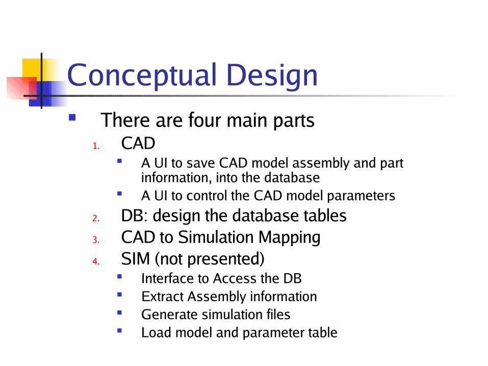
Conceptual Design There are four main parts
1. CAD A UI to save CAD model assembly and part
information, into the database A UI to control the CAD model parameters
2. DB: design the database tables3. CAD to Simulation Mapping4. SIM (not presented)
Interface to Access the DB Extract Assembly information Generate simulation files Load model and parameter table

CAD Component Integrate User-interfaces into CAD
Adding a UI to SolidEdge
Adding the created UI to SolidEdge
SolidEdge, with a new UI

CAD componentExtracting Assembly information
Part: Name, position,
rotation, … Physical
Properties Mass, Volume…
Relations Axial joint

CAD Component User-Interface to control CAD parameters

DB Component Brief look at the Database tables

CAD to Simulation Mapping The mapping is an association
between1. CAD Assemblies and Parts on the one
hand2. And Modelica models on the other
Must be careful when both Assemblies and Part have modelica equivalents

Example Mapping CAD Solar Panel
Simulator Solar Panel

Example Mapping CAD
Spacecraft Structure
Simulator S/C Structure

Example Mapping CAD Torque
Rod Assembly
Simulator Torque Rod Assembly

Example Mapping CAD Thruster
Simulator Thruster
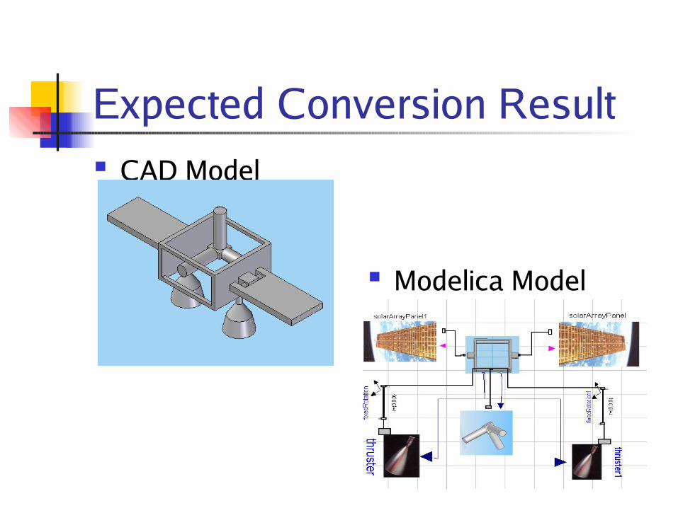
Expected Conversion Result CAD Model
Modelica Model

Expected Conversion Result CAD Demo Modelica Demo

Status All major technical components of the
design have been exercised No foreseeable technical difficulties Conversion from CAD to Modelica now
possible, however reverse process requires an upcoming release of Dymola (or MSDL compiler)

Conclusion Approach looks promising
CAD model translated to multidisciplinary simulation model
Will eventually allow to completely link CAD model to all related simulation models
Much work still required Modeling all possible user behaviors on both the
CAD and Modelica tools Reevaluate system architecture accordingly Continue developing the interfaces