Embed Size (px)
Citation preview
©2010 Advantech Corporation, Industrial Automation Group. www.advantech.com/ea
Integrating Distributed Energy Resources into the Smart Grid Written by: Gary Frederich & Patric Dove, Advantech Corporation, Industrial Automation Group
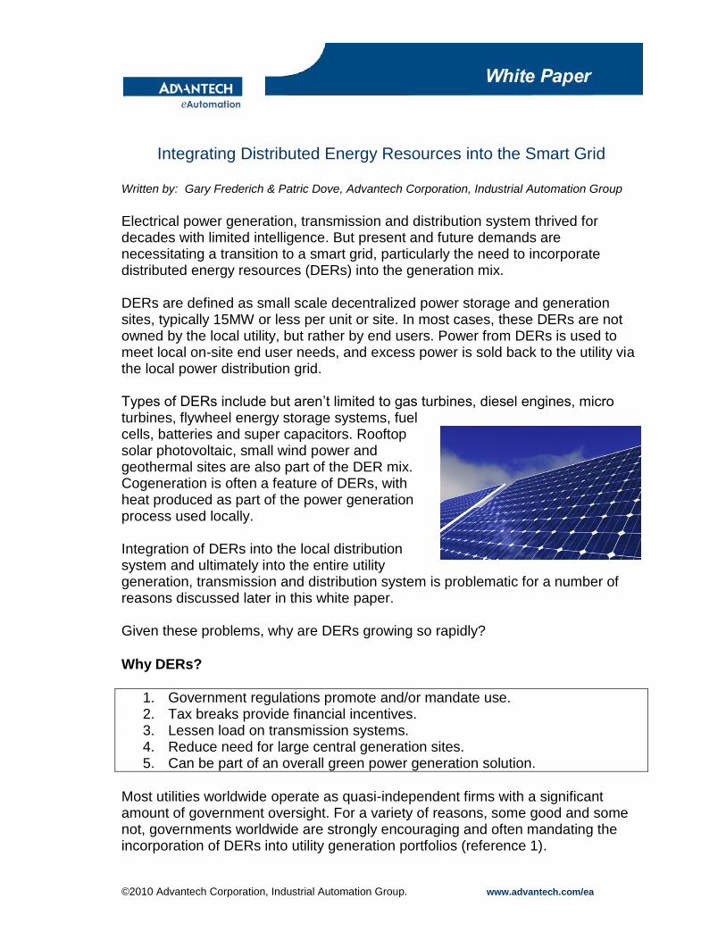
Electrical power generation, transmission and distribution system thrived for decades with limited intelligence. But present and future demands are necessitating a transition to a smart grid, particularly the need to incorporate distributed energy resources (DERs) into the generation mix. DERs are defined as small scale decentralized power storage and generation sites, typically 15MW or less per unit or site. In most cases, these DERs are not owned by the local utility, but rather by end users. Power from DERs is used to meet local on-site end user needs, and excess power is sold back to the utility via the local power distribution grid. Types of DERs include but aren’t limited to gas turbines, diesel engines, micro turbines, flywheel energy storage systems, fuel cells, batteries and super capacitors. Rooftop solar photovoltaic, small wind power and geothermal sites are also part of the DER mix. Cogeneration is often a feature of DERs, with heat produced as part of the power generation process used locally. Integration of DERs into the local distribution system and ultimately into the entire utility generation, transmission and distribution system is problematic for a number of reasons discussed later in this white paper. Given these problems, why are DERs growing so rapidly?
Why DERs?
1. Government regulations promote and/or mandate use. 2. Tax breaks provide financial incentives. 3. Lessen load on transmission systems. 4. Reduce need for large central generation sites. 5. Can be part of an overall green power generation solution.
Most utilities worldwide operate as quasi-independent firms with a significant amount of government oversight. For a variety of reasons, some good and some not, governments worldwide are strongly encouraging and often mandating the incorporation of DERs into utility generation portfolios (reference 1).
©2010 Advantech Corporation, Industrial Automation Group. www.advantech.com/ea
In the U.S., “29 states have enacted explicit targets for renewable energy production, and 16 states of the 29 have goals for production of energy from distribution generation” (reference 2). Debating the wisdom of government DER promotion is beyond the scope of this white paper. Suffice to say that governments are promoting the use of DERs worldwide and will continue to do so, probably on an increasing basis. One of the good reasons why governments are promoting DER use is because they lessen the load on utility transmission and distribution systems. Power generated locally on a distributed basis is used in one of two ways: either on-site by the owner or by other users through the power distribution system. Power used on-site by the owner reduces the load on the local distribution system and ultimately on the higher voltage transmission system. Power produced by a DER and not used by the owner is fed back into the utility local power distribution system. Although it’s impossible to track the exact path of power through the grid, it stands to reason that much of the power produced by DERs stays within local distribution and never reaches the higher voltage level of the transmission system. Another good reason for the growth of DERs is that they reduce the need for large centralized power generation plants. As with high voltage transmission lines, getting government approvals for these large centralized plants is very difficult, time-consuming and expensive. Hindering construction of large centralized plants and high voltage transmission systems is another way that governments worldwide promote DERs (reference 3). Finally, DERs can be part of an overall green power generation solution. When DERs are renewable, the green impact is obviously positive and DERs can be a good way to incorporate renewables into the generation mix. Some types of renewable DERs such as geothermal sites are inherently local and usually relatively small in capacity, making them well suited to distributed rather than centralized generation. On the other hand, DERs burning fossil fuels actually increase overall emissions as compared to large centralized power plants. This is due in part to the strict rules government agencies, such as California’s AQMD, impose on large centralized plants. But because of their lower MW output and favored regulatory status, most DERs are exempt from these emissions standards (reference 4). For both regulatory and technical reasons, a small fossil fuel plant will produce more emissions than a larger plant on a per megawatt basis. It’s also much harder to monitor and regulate emissions from many smaller sites as opposed to fewer and larger sites.
©2010 Advantech Corporation, Industrial Automation Group. www.advantech.com/ea
There are various methods for making fossil-fueled DERs greener, chief among them cogeneration. With cogeneration, waste heat produced as a by-product of power generation is used locally by the DER. This waste heat is typically used to produce hot water or steam for space heating. When DERs are located at manufacturing plants, co-generated steam is often used as part of the production process. Although cogeneration doesn’t directly reduce emissions, it does increase overall efficiency by making use of waste heat. For a number of reasons as outlined above, DERs are here to stay and will grow in use. But it’s undeniable that DERs pose a number of problems for utilities, primarily at the local distribution level, but also in terms of balancing generation with demand.
When Utilities Ruled the World To understand the problems posed by DERs, it helps to look at the utility landscape prior to their introduction. Before the advent of DERs and independent power producers (IPPs), most utilities produced all of their power from a relatively small number of large centralized generation facilities (reference 5). Power output from these generation facilities was ramped up and down to meet customer demands. Some efforts were made to control demand, primarily by shaving peak loads, but most efforts were focused on building sufficient infrastructure to provide power no matter the circumstances. IPPs emerged in the U.S. during the 1980s. IPPs were connected to the grid but not owned by the utility, and controlling their power output was much more difficult than with utility owned facilities. Utility owned generation facilities are operated with the primary goal of providing power to customers on a predictable and reliable basis. The primary goal of IPPs is to make money by running their facilities at maximum efficiency. These conflicting aims can cause problems because power from IPPs may not be available when needed most by utility customers. Through various agreements, utilities work with IPPs to reconcile conflicts, but it’s often difficult to integrate IPPs into the generation mix. With DERs, the same basic conflict between reliability and profitability exists, but other factors make integration even more difficult. In terms of sheer size and numbers, DERs are much smaller than IPP facilities and a lot more numerous. It’s much easier for a utility to negotiate reliability agreements with a few large IPPs as opposed to many small DERs. Monitoring compliance with these agreements and assessing penalties where necessary is also much more difficult with DERs than with IPPs.
©2010 Advantech Corporation, Industrial Automation Group. www.advantech.com/ea
Both IPPs and DERs must comply with design and test standards for safe integration into the utility system, namely IEEE 1547 (reference 6). Assuring compliance with these standards is again easier for larger and fewer IPPs as opposed to smaller and more numerous DERs. The bottom line is that IPPs and DERs have greatly complicated the utility generation equation. But that’s not the only impact, as local distribution systems also face issues when integrating DERs. Beware the Back Feed Before the advent of IPPs and DERs, local utility power distribution systems received all of their power from central generating plants via transmission lines. Power was generated and stepped up to transmission voltage levels over 100kV, then in some cases down to sub-transmission levels of 34.5-69kV. Substations stepped transmission and sub-transmission voltages down to more manageable levels for local distribution, typically in the 4-15kv range. Then as now, substations act as the hub of the local utility power distribution system. Once power is stepped down via substation transformers, it’s then distributed through circuit breakers to feeder lines. Each feeder line typically accommodates a few thousand utility residential customers, or a much smaller number of larger commercial or industrial customers. Over the years, utilities have devised a number of methods to find and repair problems on their distribution systems, all predicated on the flow of power through transmission and distribution systems from upstream generation to downstream customers. Frequent maintenance has kept problems to a minimum, but safely performing these activities often depends on the predictable power flow of a radial distribution system. DERs change the nature of power flows through the local distribution system, adding complexity and possible dangers. When all power is coming from upstream sources, it’s relatively simple to manage power flows as required for repairs and maintenance. Local distribution systems are designed so that sectionalizing devices such as circuit breakers, line reclosers, and manual switches/disconnects can route power through the system and around areas where work needs to be performed. Once an upstream device is locked out and tagged out, utility crews can be confident that the line is dead and safe for work. With DERs, power can be fed back into the local distribution system from a variety of sources located throughout the service area. Locking and tagging out a
©2010 Advantech Corporation, Industrial Automation Group. www.advantech.com/ea
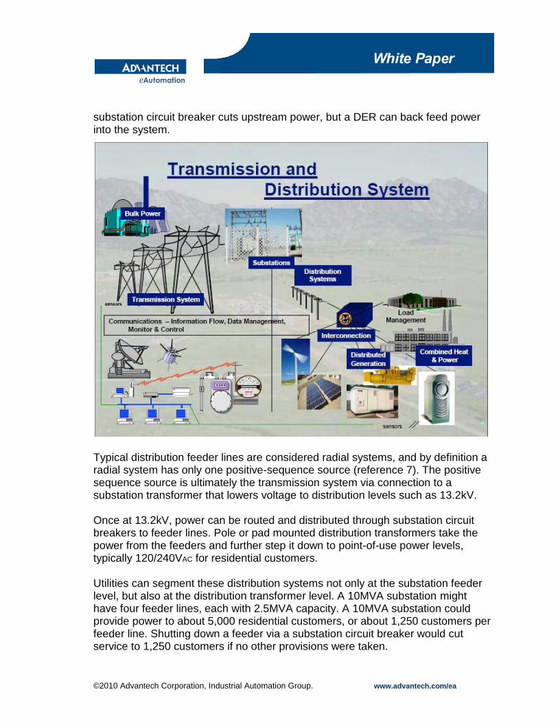
substation circuit breaker cuts upstream power, but a DER can back feed power into the system.
Typical distribution feeder lines are considered radial systems, and by definition a radial system has only one positive-sequence source (reference 7). The positive sequence source is ultimately the transmission system via connection to a substation transformer that lowers voltage to distribution levels such as 13.2kV. Once at 13.2kV, power can be routed and distributed through substation circuit breakers to feeder lines. Pole or pad mounted distribution transformers take the power from the feeders and further step it down to point-of-use power levels, typically 120/240VAC for residential customers. Utilities can segment these distribution systems not only at the substation feeder level, but also at the distribution transformer level. A 10MVA substation might have four feeder lines, each with 2.5MVA capacity. A 10MVA substation could provide power to about 5,000 residential customers, or about 1,250 customers per feeder line. Shutting down a feeder via a substation circuit breaker would cut service to 1,250 customers if no other provisions were taken.
©2010 Advantech Corporation, Industrial Automation Group. www.advantech.com/ea
A typical 10kVA distribution transformer feeds only a few score of residential customers, and these distribution transformers are provided with local and usually manual switches to control power flow. So once a problem or an area needing maintenance is located, power can be cut at the distribution transformer level. That’s why outages often result in a row of houses without power, while homes or businesses on the next street are up and running. But what if one of the utility customers owns and operates a DER, let’s say a natural gas cogeneration system? In this case, the distribution system is no longer a radial system. This complicates the protective relaying scheme which assumes the distribution feeder is radial. A common problem with adding downstream generation to a radial feeder system is desensitizing over-current relays such that they no longer trip on electrical faults. Other problems often arise during planned and unplanned shutdowns. Utility crews generally assume a radial system and shut off all upstream power sources at either the substation feeder or the distribution transformer level. With DERs, power can still be back fed into the system, creating a very dangerous and possibly lethal situation. To deal with this issue, utilities require each DER to have an interconnection system that trips the generator and isolates it from the distribution system when it senses a loss of utility voltage. This is typically done by protective relays internal to the generating facility or by a direct transfer trip signal from the substation. Recommended practices for implementing interconnection systems can be found in IEEE standard 1547. More specific implementation instructions are often implemented at the utility level, such as with Southern California Edison’s Rule 21 (reference 8). The more there are DERs, the more interconnection systems and the more complex the local power distribution system. But that’s not the only way DERs add complexity to the local power distribution system. Balancing the power demands of each DER customer is now a significant issue, as demand must be fed by a continuously changing mix of utility provided and DER power. Where’s My Power? For a customer without an on-site DER, meeting power demand is relatively simple. The utility simply monitors voltage levels and makes sure that voltage is sufficiently high to allow the customer to draw their required amps of current. When voltage dips, the power system is adjusted accordingly. Power delivered to the customer is measured by a meter, and the customer is billed accordingly.
©2010 Advantech Corporation, Industrial Automation Group. www.advantech.com/ea
But what happens when a customer produces their own power via a DER? First, the customer still wants the utility to maintain a delivery system sufficient to provide all of their power needs for times when their DER is not operating. Second, the customer wants the utility to provide partial power for times when their DER is meeting some but not all of their power needs. Third, the customer wants to be able to sell all power in excess of their needs back to the utility. This is obviously a much more complex scenario than that of a typical customer, and it raises a number of problems for the utility. Power flowing back into the grid must be accurately measured, and appropriate adjustments must be made to DER customer utility bills. As mentioned earlier, there will be times when the utility simply can’t allow the DER customer to back feed power into the system - and there must be a simple, low cost and reliable way to ensure that power is not fed back into the system. Synchronization between the DER and the power grid is also critical (reference 9). Rotating machinery power generation equipment such as gas turbines and diesel engines must be synced to grid frequency. If a DER gas turbine is connected to the grid 180 degrees out of phase, it will immediately be jerked back into sync and destroyed. Other types of DERs have different but related synchronization issues. For local control and for integration into the utility system, DERs need to employ automation systems to monitor conditions and control equipment. Fortunately, many practical automation solutions are already in place, with more being developed and implemented to match the growth of DERs. Overcoming DER Challenges with Automation Each DER site must have some level of automation to control and protect its specific type of power generation equipment, and to interface this equipment to the grid. Automation systems will range from very complex for control of a gas turbine to very simple for control of a small wind power installation. IEEE standard 1547 makes reference to “interconnection systems”, and the automation system is part of the interconnection system. DER automation systems typically consist of three main parts: the controller, the I/O and the operator interface. The I/O connects the controller to components such as valves, switches and motors. The controller monitors inputs, makes decisions based on its internal software program and adjusts outputs accordingly. In many modern automation systems, the controller is actually an industrial PC, often referred to as a Programmable
©2010 Advantech Corporation, Industrial Automation Group. www.advantech.com/ea
Automation Controller (PAC) such as Advantech’s APAX product series. A PAC provides a ruggedized component that can be easily interfaced to both the utility and to various DER electrical and electronic components. The operator interface is typically an LED monitor or a simple alpha numeric display that provides a view of the process being controlled. Most operator interface panels also provide a means of control and adjustment. In addition to control of the DER’s power generating equipment, automation must be provided for monitoring and control of the components used to interface the generating equipment to the local utility distribution system. These components include but aren’t limited to automatic transfer switches, synchronization check devices and direct transfer trip relays. Automation systems address the DER grid integration issues listed below and discussed above
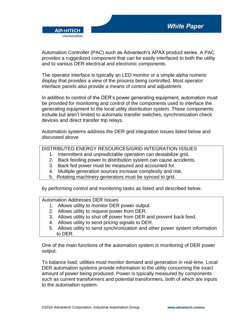
DISTRIBUTED ENERGY RESOURCES/GRID INTEGRATION ISSUES 1. Intermittent and unpredictable operation can destabilize grid. 2. Back feeding power to distribution system can cause accidents. 3. Back fed power must be measured and accounted for. 4. Multiple generation sources increase complexity and risk. 5. Rotating machinery generators must be synced to grid.
by performing control and monitoring tasks as listed and described below.
Automation Addresses DER Issues 1. Allows utility to monitor DER power output. 2. Allows utility to request power from DER. 3. Allows utility to shut off power from DER and prevent back feed. 4. Allows utility to send pricing signals to DER. 5. Allows utility to send synchronization and other power system information
to DER.
One of the main functions of the automation system is monitoring of DER power output. To balance load, utilities must monitor demand and generation in real-time. Local DER automation systems provide information to the utility concerning the exact amount of power being produced. Power is typically measured by components such as current transformers and potential transformers, both of which are inputs to the automation system.
©2010 Advantech Corporation, Industrial Automation Group. www.advantech.com/ea
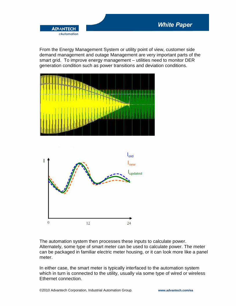
From the Energy Management System or utility point of view, customer side demand management and outage Management are very important parts of the smart grid. To improve energy management – utilities need to monitor DER generation condition such as power transitions and deviation conditions.
The automation system then processes these inputs to calculate power. Alternately, some type of smart meter can be used to calculate power. The meter can be packaged in familiar electric meter housing, or it can look more like a panel meter. In either case, the smart meter is typically interfaced to the automation system which in turn is connected to the utility, usually via some type of wired or wireless Ethernet connection.
©2010 Advantech Corporation, Industrial Automation Group. www.advantech.com/ea
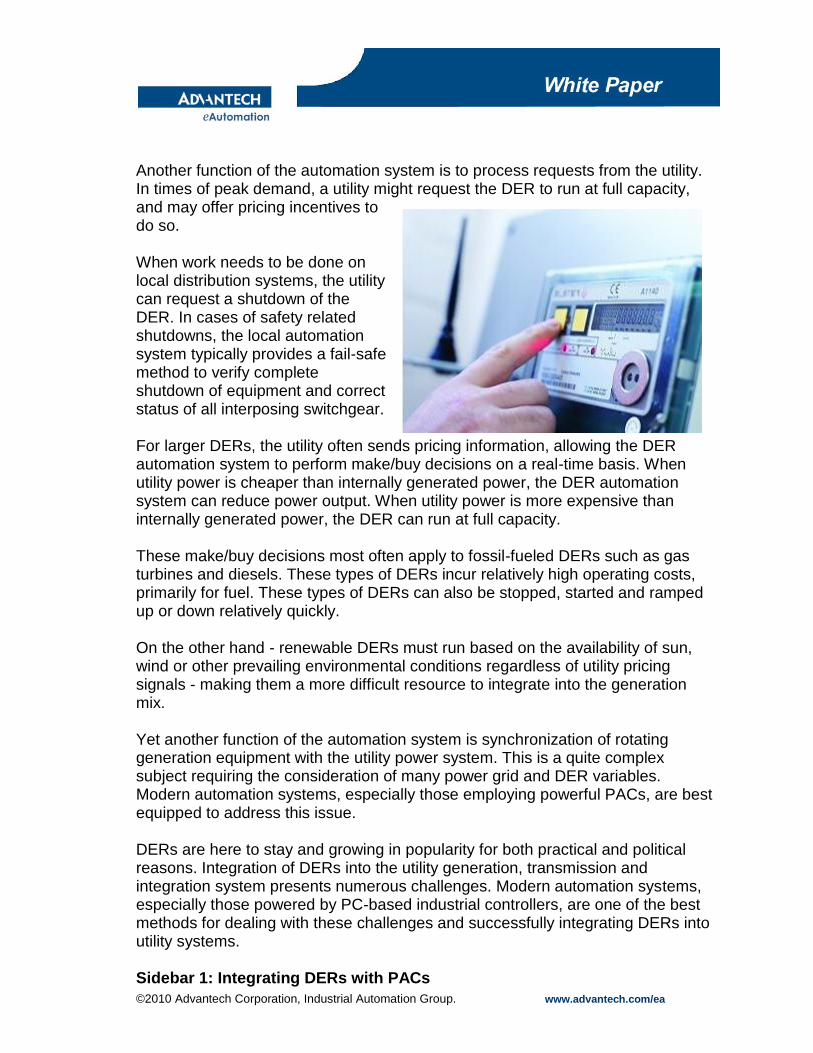
Another function of the automation system is to process requests from the utility. In times of peak demand, a utility might request the DER to run at full capacity, and may offer pricing incentives to do so. When work needs to be done on local distribution systems, the utility can request a shutdown of the DER. In cases of safety related shutdowns, the local automation system typically provides a fail-safe method to verify complete shutdown of equipment and correct status of all interposing switchgear. For larger DERs, the utility often sends pricing information, allowing the DER automation system to perform make/buy decisions on a real-time basis. When utility power is cheaper than internally generated power, the DER automation system can reduce power output. When utility power is more expensive than internally generated power, the DER can run at full capacity. These make/buy decisions most often apply to fossil-fueled DERs such as gas turbines and diesels. These types of DERs incur relatively high operating costs, primarily for fuel. These types of DERs can also be stopped, started and ramped up or down relatively quickly. On the other hand - renewable DERs must run based on the availability of sun, wind or other prevailing environmental conditions regardless of utility pricing signals - making them a more difficult resource to integrate into the generation mix. Yet another function of the automation system is synchronization of rotating generation equipment with the utility power system. This is a quite complex subject requiring the consideration of many power grid and DER variables. Modern automation systems, especially those employing powerful PACs, are best equipped to address this issue. DERs are here to stay and growing in popularity for both practical and political reasons. Integration of DERs into the utility generation, transmission and integration system presents numerous challenges. Modern automation systems, especially those powered by PC-based industrial controllers, are one of the best methods for dealing with these challenges and successfully integrating DERs into utility systems. Sidebar 1: Integrating DERs with PACs
©2010 Advantech Corporation, Industrial Automation Group. www.advantech.com/ea
Until about a 20 years ago, Programmable Logic Controllers (PLCs) were at the heart of most every automation system, and operator interface terminals were typically custom designed and vendor-proprietary displays. Around 1990, PCs began to emerge as a viable option as the main controller in an automation system. When a PC was used for control, it was a natural fit to employ a PC monitor as the operator interface. In response to market demand, suppliers re-packaged PCs into form factors suitable for industrial use. Operating specifications were improved in terms of allowable temperatures and shock and vibration levels – as was resistance to electrical noise and interference. Reliability was also improved at both the hardware and software levels. The end result was the industrial PC, sometimes referred to as a Programmable Automation Controller (PAC, see reference 10). The PAC is proving to be a good fit for DER automation applications for a number of reasons. In most all instances, a DER automation system must be connected to utility control and communication systems. The most popular communication network for this purpose is Ethernet, and most all PACs feature built-in Ethernet support along with Internet connectivity. DER applications often require interface to a number of different electrical and electronic components including electric power meters and protective relays. Unlike PLCs, it’s relatively easy to interface a PAC to these components. PACs typically feature multiple communication ports conforming to various utility industry hardware connection standards such as Ethernet, Modbus RTU, DNP3 and others. The ability to communicate with different communications protocols was a low priority before the advent of microprocessor-based relays and meters, but now it’s a necessity. By connecting to microprocessor-based devices via digital networks - PACs can download event data with millisecond precision, monitor real-time current and voltage and perform remote maintenance testing. Programming a PAC to interpret different communication protocols is relatively straightforward as most PACs can be programmed via a number of popular languages. Among industrial controllers, PACs feature the widest range of discrete and analog I/O. This makes it relatively easy to interface a PAC in a hard-wired manner to the many different types of electrical components in a DER.
©2010 Advantech Corporation, Industrial Automation Group. www.advantech.com/ea
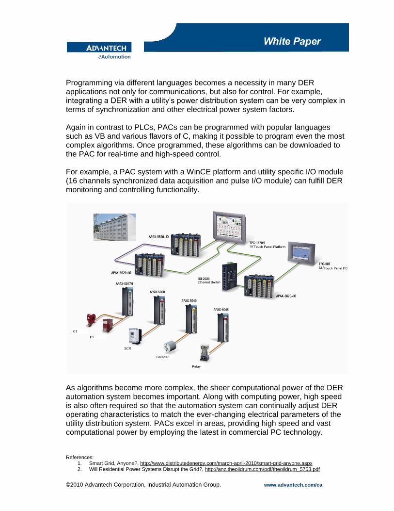
Programming via different languages becomes a necessity in many DER applications not only for communications, but also for control. For example, integrating a DER with a utility’s power distribution system can be very complex in terms of synchronization and other electrical power system factors. Again in contrast to PLCs, PACs can be programmed with popular languages such as VB and various flavors of C, making it possible to program even the most complex algorithms. Once programmed, these algorithms can be downloaded to the PAC for real-time and high-speed control. For example, a PAC system with a WinCE platform and utility specific I/O module (16 channels synchronized data acquisition and pulse I/O module) can fulfill DER monitoring and controlling functionality.
As algorithms become more complex, the sheer computational power of the DER automation system becomes important. Along with computing power, high speed is also often required so that the automation system can continually adjust DER operating characteristics to match the ever-changing electrical parameters of the utility distribution system. PACs excel in areas, providing high speed and vast computational power by employing the latest in commercial PC technology.
References: 1. Smart Grid, Anyone?, http://www.distributedenergy.com/march-april-2010/smart-grid-anyone.aspx 2. Will Residential Power Systems Disrupt the Grid?, http://anz.theoildrum.com/pdf/theoildrum_5753.pdf
©2010 Advantech Corporation, Industrial Automation Group. www.advantech.com/ea
3. Congressman Ed Markey Wants to Expand Nuclear Bureaucracy, http://nuclearfissionary.com/2010/03/11/congressman-ed-markey-want-to-expand-nuclear-bureaucracy/
4. REGULATION 9, INORGANIC GASEOUS POLLUTANTS, RULE 9, NITROGEN OXIDES FROM STATIONARY GAS TURBINES, http://www.baaqmd.gov/~/media/Files/Planning%20and%20Research/Rules%20and%20Regs/reg%2009/rg0909.ashx
5. Electric Power Industry Overview 2007, http://www.eia.doe.gov/cneaf/electricity/page/prim2/toc2.html#non 6. IEEE 1547 Standard for Interconnecting Distributed Resources with Electric Power Systems,
http://grouper.ieee.org/groups/scc21/1547/1547_index.html 7. Protective Relaying: Principles and Applications, Blackburn, J. Lewis. Florida: CRC Press, 2007. 8. Rule 21, Generating Facility Interconnections, http://www.sce.com/NR/sc3/tm2/pdf/Rule21.pdf 9. Synchronizing Renewable Energy Sources in Distributed Generation Systems, http://www.icrepq.com/full-paper-
icrep/334-ramos.pdf 10. Programmable Automation Controllers Find Their Niche…Everywhere!,
http://www.automationworld.com/images/sponsored_content/wp_advantech_pac.pdf
###