Embed Size (px)
Citation preview

Integration Guide
2007

1 PrintedonRecycledPaper•Copyright2007®
Welcome
OutBack Power Systems is proud to begin another year of designing and manufacturing solutions with you, the customer, in mind. OutBack maintains the philosophy that listening to our customers and innovating to meet their needs is paramount to our success. This past year OutBack’s engineering, marketing and operations teams have been focusing on taking the suggestions provided by our customers to develop a new line of products called FLEXware. FLEXware is an evolution in balance of system components which are simple to order, easy to assemble and fast to install. In conjunction with this product development, we have made efforts to further enhance our industry-leading level of customer service by building our team of qualified technical and order service personnel. OutBack is excited about what the future will bring. We will continue to listen to and learn from our customers, and continue to innovate. The power electronics and communications technologies we have developed over the past several years will allow OutBack to continue to provide the cutting edge solutions our customers are looking for as we move ahead. We are confident that OutBack will continue to lead the way in bringing the solutions and services that people have come to depend on. Thank you for your support as we continue Powering the Planet.
History
2001OutBack was started by a passionate group of engineers who wanted to bring power conversion electronics technology into the 21st century.
Thissmallstartupquicklygrewbyofferinginnovativeandwelldesignedsolutionstorenewableenergyproblems.OutBacklistenedtotheircustomersandmademanyofthechangesthatweresuggested,creatingatrulycustomerfocusedcompanyinthepowerconversionelectronicsindustry.
2002OutBack introduces its first sealed sinewave inverter/charger, the FX2024 - with resounding success.
Thissinglemodelchangedthewaypeoplelookedatsystemdesignbyofferingunprecedentedflexibilityinsystemdesignandexpansionwhilethesealedconstructionallowedforuseswhichpreviouslywouldhavebeenconsideredtoo“extreme”forotherinverter/chargers.
OutBackreleasestheMX60solarMPPTChargeControllerredefiningperformanceandvalue.
ThisrevolutionaryproductchangedthewaysolarsystemswerebeinginstalledandquicklygainedareputationforgettingthemostpowerpossiblefromaPVarray-oftenmakingitmoreexpensivetonotuseone.
2003OutBack launches the first of the vented versions of the FX Series inverter/chargers.
TheseVFXmodelswereintroducedindirectresponsetoourcustomer’srequestsprovidinghigherpoweratasimilarpriceasthesealedcounterpart.
OutBacklaunchesthePS2,valuepricedsystemintegrationaccessories.
Thislineofaccessoriesaddressedtheneedsofourcustomersforcompetitivelypricedsystemintegrationaccessoriesforsmallersystems.
2004OutBack releases the world’s most efficient grid-interactive inverter/charger.
Thesemodelsraisethebarforperformanceandvalueforbattery-connectedgrid-interactiveinverter/chargersystems.OutBackintroducesthePS1fullyintegratedgrid-interactivepowersystem.
Thisuniquesystemsetsanewstandardforsystemintegration,performanceandeaseofinstallationingrid-interactiveapplications.
2005OutBack reaches milestones in product deliveries and product recognition.
MX60 and FX Inverter production lines each ship 10,000th unit.
OutBackPowerequippedteamssweepthetopthreeplacesinthe2005SolarDecathlon,acompetitionbetweenInternationaluniversitiestodevelopandbuildthemostenergyefficienthome.
2006OutBack launches FLEXware, a new line of balance of system components.

2
Introducing the FLEXware System
FLEXware is the latest example of OutBack’s continuous efforts to bring you the most value packed and technologically advanced products available.
Our integrating partners, dealers, installers, and system owners spoke–and we listened. The resulting FLEXware is the most integrated, modular, and spacious installation system OutBack has ever designed. Its components are more versatile, the wiring space is larger, and the all-aluminum, powder-coated construction not only resists corrosion longer, but is lighter and easier to handle than our previous steel construction. OutBack’s new FLEXware makes for a great looking installation that will look great for years and years to come.
Designed to work as a modular “building block” architecture, FLEXware offers more versatility than ever before. From single inverter back-up systems to a multiple inverter village power system – FLEXware is the solution.
The FLEXware 250 offers the lowest cost solution for single inverter/charger installations when space and budget are primary concerns.
The FLEXware 500 supports up to two inverter/chargers and two charge controllers in an attractive, versatile and code-compliant package when more power is needed.
The FLEXware 1000 accommodates up to four inverter/chargers and four charge controllers. It can also be used for large systems with multiple power panels for systems up to 36 kW.
Both the FLEXware 500 and FLEXware 1000 systems provide ample locations for additional breakers, DC current shunts, an autotransformer and other items required in higher kW systems.
The new FLEXware MP mounting plate shows the versatility of the FLEXware system with its compatibility with both the FLEXware 500 and FLEXware 1000 systems.
All of the FLEXware options have also been simplified, making the design, ordering and installation of power system easier than ever.

250For applications with modest power requirements such as cabins, remote communication sites and back-up power systems. The FLEXware 250 accommodates all of the essential protective devices in the smallest possible space at the lowest installed cost. Utilizing an extremely compact design and unique mounting features, one or two FLEXware 250 enclosures can be mounted on each end of a single FX Series Inverter/Charger. The FLEXware 250 enclosure is contructed of power-coated aluminum and has been ETL listed. It provides breaker spaces for battery, PV array or PV GFP breakers and mounting locations for AC GFCI outlet, AC breakers and even an Input-Output-Bypass Assembly. In keeping with the philosophy of FLEXware, the FLEXwares 250 flexibility is evident in the generous number of knock-outs allowing the installation of conduit, cable glands and other installation accessories.
3
Breaker Configuration Diagram
AC Side DC Side
Knockout Location Diagram
Holdsonelarge1.5”(39mm)wide175or250Ampbreaker.IncludeslargeDCbreakerguard.
Holdsuptofoursmall0.75”(19mm)wideACratedpanelmountbreakers(notincluded).Thesmallsizesareratedfor1-60AmpsofACcurrent.SupportforoptionalACInput-Output-BypassAssembly.
Holdsuptofoursmall0.75”(19mm)wideDCratedpanelmountbreakers(notincluded).Thesmallsizesareratedfor1-80AmpsofDCcurrent.
Holdsonegroundfaultduplexreceptacle.
ACSide• (1)2”knockout(2.468”diameter)• (1)1”knockout(1.359”diameter)• (1)¾”knockout(1.093”diameter)
DCside• (1)2”knockout(2.468”diameter)• (2)½”knockout(0.875”diameter)
Back• (1)2”knockout(2.468”diameter)• (2)1”knockout(1.359”diameter)
Bottom• (1)2”knockout(2.468”diameter)

4
FLEXware 250
Model: FW250
Description: DCand/orACbreakerenclosureforoneFXSeriesInverter/Charger
Includes: Groundbusbar,DCbreakerhandleguard,breakermountinghardwareandenclosuremountinghardware
Unit Dimensions (H x W x D) Shipping Dimensions (H x W x L) Shipping Weight Enclosure Type 7.5x6.5x8.6”(19.1x16.5x21.8cm) 9.75x8.4x11.6”(24.8x21.3x29.5cm) 5lbs.(2.3kg) Type-1indoor(IP30)
Holdsuptoeight1to80Amp,one175or250AmppanelmountbreakerandaGFCIACoutlet(notincluded).•DoesnotusetheDCAorACAforconnectiontoanFXInverter/Charger.•DCcurrentshuntnotincluded
FLEXware 250 AC Input-Output-Bypass AssembliesFieldinstallablekitforbypassingtheACinputtotheACoutputforinvertermaintainenceorinstallation.Alsoprovidesover-currentprotection.
Model: FW-IOB-S-120VAC
Includes:Three60A120VACsinglepolePANELmountbreakers,slidingbypassinterlockplate,wireandhardwardkit
System Rating Bypass Breaker Input Breaker Output Breaker
SinglePhase120VAC [email protected] [email protected] [email protected] 60Amp7.2kW
Model: FW-IOB-S-230VAC
Includes:Three30A120VACsinglepolePANELmountbreakers,slidingbypassinterlockplate,wireandhardwarekit
System Rating Bypass Breaker Input Breaker Output Breaker
SinglePhase230VAC [email protected] [email protected] [email protected] 30Amp6.9kW

Knockout Location Diagram
Breaker Configuration Diagram
AC Side DC Side
For applications with medium power requirements such as homes, light commercial or larger back-up power systems. The FLEXware 500 system architecture is capable of supporting up to two OutBack FX Series Inverter/Chargers, up to two MX60 Charge Controllers and all the associated AC and DC components. Thanks to a very compact design, FLEXware 500 AC and DC enclosures mount with a FLEXware MP in either a horizontal or vertical orientation to allow installation in more space limited locations for a fast and professional looking wall-mounted installation. The FLEXware 500 accommodates all of the essential protective devices in two enclosures.
5
HoldsuptosixteenDINmountACbreakers(notincluded).SupportforoptionalACInput-Output-BypassAssembly.ACbreakersareratedfrom10-16AmpsofACcurrent.
Holdsuptoeightsmall0.75”(19mm)wide,threemedium1”(26mm)wideortwolarge1.5”(32mm)wideDCratedbreakers.Thesmallareratedfor1-80Amps,mediumfor100or125Ampsandthelargeareratedfor175or250AmpsofDCcurrent.
500
Back• (2)2”knockout(2.468”diameter)
Left• (5)1”knockout(1.359”diameter)• (2)2”knockout(2.468”diameter)• (2)DuplexGFCIOutletknockout
Right• (9)1”knockout(1.357”diameter)
Top• (3)1”knockout(1.359”diameter)• (1)¾”knockout(1.093”diameter)• (4)2”knockout(2.468”diameter)
Bottom• (3)1”knockout(1.359”diameter)• (1)¾”knockout(1.093”diameter)• (4)2”knockout(2.468”diameter)

6
FLEXware 500
Model: FW500-DC
Description: DCenclosurewhichmountsattheDCsideofoneortwoFXSeriesInverter/Chargers.Supportssixterminalbusbars(notincludingGBB)andthreeshuntassemblies.
Includes:Groundbusbar,500AmpDCshuntassembly,positivebus,breakermountinghardware,FW-BBUSandenclosuremountinghardware
Unit Dimensions (H x W x D) Shipping Dimensions (H x W x L) Shipping Weight Enclosure Type 18.2x11.4x12.1”(46.2x29x30.7cm) 14.5x13.4x20.3”(36.8x34.1x51.6cm) 15lbs.(6.8kg) Type-1indoor(IP30)
Model: FW500-AC
Description: ACenclosurewhichmountsattheACsideofoneortwoFXSeriesInverter/Chargers.Supportssixterminalbus
barsandoneFW-X240.
Includes: Groundbusbar,DINmountingbracket,communicationcableconduitandenclosuremountinghardware
Unit Dimensions (H x W x D) Shipping Dimensions (H x W x L) Shipping Weight Enclosure Type 18.2x11.4x12.1”(46.2x29x30.7cm) 14.5x13.4x20.3”(36.8x34.1x51.6cm) 15lbs.(6.8kg) Type-1indoor(IP30)
•TheFW500systemutilizesoneFW-MPmountingplateandasetoftheDCAandACAconduitadaptersforeachinverter/charger. •DCandACbreakers,Input-Output-BypassAssembliesandallotheradditionalcomponentssoldseparately.
FLEXware 500 AC Input-Output-Bypass AssembliesFieldinstallablekitforbypassingtheACinputtotheACoutputforinvertermaintainenceorinstallation.Alsoprovidesover-currentprotection.
Model: FW-IOB-D-120/240VAC
Includes: Six60A120VACsinglepoleDINmountbreakers,slidingbypassinterlockplate,wireandhardwarekit
System Rating Bypass Breaker Input Breaker Output Breaker SplitPhase120/240VAC [email protected] [email protected] [email protected]
Model: FW-IOB-D-120VAC
Includes: Six60A120VACsinglepoleDINmountbreakers,slidingbypassinterlockplate,wireandhardwarekit
System Rating Bypass Breaker Input Breaker Output BreakerSinglePhase120VAC [email protected] [email protected] [email protected]
Model: FW-IOB-D-230VAC
Includes: Six30A230VACsinglepoleDINmountbreakers,slidingbypassinterlockplate,wireandhardwarekit
System Rating Bypass Breaker Input Breaker Output Breaker SinglePhase230VAC [email protected] [email protected] [email protected]

Knockout Location Diagram
For applications with large power requirements such as large residential, commercial or village power systems. The FLEXware 1000 system architecture is capable of supporting up to four OutBack FX Series Inverter/Chargers, four MX60 Charge Controllers, and all the required AC and DC components and wiring. Utilizing a compact design, FLEXware 1000 AC and DC enclosures accommodate all of the essential protective devices with lots of room for additional breakers and large cable connections and can be mounted either vertically or horizontially.
Breaker Configuration Diagram AC Side DC Side
7
Holdsuptothirty-twoDINmountACbreakers(notincluded).SupportforoptionalACInput-Output-BypassAssembly.ACbreakersareratedfrom10-60AmpsofACcurrent.
Holdsuptoelevensmall0.75”(19mm)wide,ninemedium1”(26mm)wideorsixlarge1.5”(32mm)wideDCratedbreakers.Thesmallareratedfor1-80Amps,themediumfor100or125Ampsandthelargeareratedfor175or250AmpsofDCcurrent.
1000
Left• (4)2”knockout(2.468”diameter)• (9)1”knockout(1.359”diameter)• (2)DuplexGFCIOutletknockout
Back• (2)2”knockout(2.468”diameter)• (2)1”knockout(1.359”diameter)
Right• (17)1”knockout(1.359”diameter)
Top• (3)1”knockout(1.359”diameter)• (1)¾”knockout(1.093”diameter)• (4)2”knockout(2.468”diameter)
Bottom• (3)1”knockout(1.359”diameter)• (1)¾”knockout(1.093”diameter)• (4)2”knockout(2.468”diameter)

8
FLEXware 1000
Model: FW1000-DC
Description:DCenclosurewhichmountsattheDCsideofthreeorfourFXInverter/Chargers.Supportseightterminalbusbars(notincludingGBB)andthreeshuntassemblies.
Includes: Groundbusbar,1000AmpDC,shuntassembly,positivebus,breakermountinghardware,enclosuremounting
hardware,twoFW-SBUSandoneFLEXware1000breakerbus
Unit Dimensions (H x W x D) Shipping Dimensions (H x W x L) Shipping Weight Enclosure Type38.5x11.4x12.1”(97.8x29.0x30.7cm) 14.5x13.6x40.6”(36.8x34.5x103.1cm) 21lbs.(9.5kg) Type-1indoor(IP30)
Model: FW1000-AC
Description:ACenclosurewhichmountsattheACsideofthreeorfourFXInverter/Chargers.SupportseightterminalbusbarsandoneFW-X240.
Includes: Groundbusbar,twoDINmountingbracketsandFLEXware1000wiringraceway
Unit Dimensions (H x W x D) Shipping Dimensions (H x W x L) Shipping Weight Enclosure Type 38.5x11.4x12.1”(97.8x29.0x30.7cm) 14.5x13.6x40.6”(36.8x34.5x103.1cm) 21lbs.(9.5kg) Type-1indoor(IP30)
•TheFW1000systemutilizestwoFW-MPmountingplateandasetoftheDCAandACAconduitadaptersforeachinverter/charger.•DCandACbreakers,Input-Output-BypassAssembliesandallotheradditionalcomponentssoldseparately.
FLEXware 1000 AC Input-Output-Bypass AssembliesFieldinstallablekitforbypassingtheACinputtotheACoutputforinvertermaintainenceorinstallation.Alsoprovidesover-currentprotection.
Model: FW-IOB-T-120/208VACIncludes: Nine60A120VACsinglepoleDINmountbreakers,slidingbypassinterlockplate,wireandhardwarekitSystem Rating Bypass Breaker Input Breaker Output Breaker ThreePhase120/208VAC [email protected] [email protected] [email protected]
Model: FW-IOB-T-230/400VACIncludes: Nine30A230VACsinglepoleDINmountbreakers,slidingbypassinterlockplate,wireandhardwarekitSystem Rating Bypass Breaker Input Breaker Output BreakerThreePhase230/400VAC [email protected] [email protected] [email protected]
Model: FW-IOB-Q-120/240VACIncludes: Twelve60A120VACsinglepoleDINmountbreakers,slidingbypassinterlockplate,wireandhardwarekitSystem Rating Bypass Breaker Input Breaker Output Breaker SplitPhase120/240VAC [email protected] [email protected] [email protected]
Model: FW-IOB-Q-120VACIncludes: Twelve60A120VACsinglepoleDINmountbreakers,slidingbypassinterlockplate,wireandhardwarekitSystem Rating Bypass Breaker Input Breaker Output Breaker SinglePhase120VAC [email protected] [email protected] [email protected]
Model: FW-IOB-Q-230VACIncludes: Twelve30A230VACsinglepoleDINmountbreakers,slidingbypassinterlockplate,wireandhardwarekitSystem Rating Bypass Breaker Input Breaker Output Breaker SinglePhase230VAC [email protected] [email protected] [email protected]
2007 OutBackPowerSystemsInc. l 8

The FLEXware MP is a one piece, powder-coated aluminum mounting plate for FLEXware 500 and FLEXware 1000 enclosures. Utilizing stainless steel mounting hardware, the integrated locating bolts make installation quick and easy by providing guides to line up enclosures and inverter/chargers. A single FLEXware MP is designed to accommodate a FLEXware 500 while two FLEXware MPs are utilized in a FLEXware 1000 configuration.
SingleMPConfigurationforFLEXware500
DualMPConfigurationforFLEXware1000
Model:FW-MP
Description:FLEXwaresystemmountingplate
Unit Dimensions (H x W x D) Shipping Dimensions (H x W x L) Shipping Weight 20.3x46.3x.8”(51.6x117.6x2.1cm) 1.15x22.9x48.4”(2.9x58.2x123cm) 14lbs.(6.4kg)
9
MP
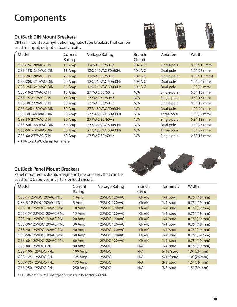
Components
10
OutBack DIN Mount BreakersDINrailmountable,hydraulic-magnetictypebreakersthatcanbeusedforinput,outputorloadcircuits.
Model Current VoltageRating Branch Variation Width Rating Circuit OBB-15-120VAC-DIN 15Amp 120VAC50/60Hz 10kAIC Singlepole 0.50”(13mm OBB-15D-240VAC-DIN 15Amp 120/240VAC50/60Hz 10kAIC Dualpole 1.0”(26mm) OBB-20-120VAC-DIN 20Amp 120VAC50/60Hz 10kAIC Singlepole 0.50”(13mm) OBB-20D-240VAC-DIN 20Amp 120/240VAC50/60Hz 10kAIC Dualpole 1.0”(26mm) OBB-25D-240VAC-DIN 25Amp 120/240VAC50/60Hz 10kAIC Dualpole 1.0”(26mm) OBB-10-277VAC-DIN 10Amp 277VAC50/60Hz N/A Singlepole 0.5”(13mm) OBB-15-277VAC-DIN 15Amp 277VAC50/60HZ N/A Singlepole 0.5”(13mm) OBB-30-277VAC-DIN 30Amp 277VAC50/60Hz N/A Singlepole 0.5”(13mm) OBB-30D-480VAC-DIN 30Amp 277/480VAC50/60Hz N/A Dualpole 1.0”(26mm) OBB-30T-480VAC-DIN 30Amp 277/480VAC50/60Hz N/A Threepole 1.5”(39mm) OBB-50-277VAC-DIN 50Amp 277VAC50/60Hz N/A Singlepole 0.5”(13mm) OBB-50D-480VAC-DIN 50Amp 277/480VAC50/60Hz N/A Dualpole 1.0”(26mm) OBB-50T-480VAC-DIN 50Amp 277/480VAC50/60Hz N/A Threepole 1.5”(39mm) OBB-60-277VAC-DIN 60Amp 277VAC50/60Hz N/A Singlepole 0.5”(13mm) •#14to2AWGclampterminals
OutBack Panel Mount BreakersPanelmountedhydraulic-magnetictypebreakersthatcanbeusedforDCsources,invertersorloadcircuits.
Model Current VoltageRating Branch Terminals Width Rating Circuit OBB-1-125VDC120VAC-PNL 1Amp 125VDC120VAC 10kAIC 1/4”stud 0.75”(19mm) OBB-5-125VDC120VAC-PNL 5Amp 125VDC120VAC 10kAIC 1/4”stud 0.75”(19mm) OBB-10-125VDC120VAC-PNL 10Amp 125VDC120VAC 10kAIC 1/4”stud 0.75”(19mm) OBB-15-125VDC120VAC-PNL 15Amp 125VDC120VAC 10kAIC 1/4”stud 0.75”(19mm) OBB-20-125VDC120VAC-PNL 20Amp 125VDC120VAC 10kAIC 1/4”stud 0.75”(19mm) OBB-30-125VDC120VAC-PNL 30Amp 125VDC120VAC 10kAIC 1/4”stud 0.75”(19mm) OBB-40-125VDC120VAC-PNL 40Amp 125VDC120VAC 10kAIC 1/4”stud 0.75”(19mm) OBB-50-125VDC120VAC-PNL 50Amp 125VDC120VAC 10kAIC 1/4”stud 0.75”(19mm) OBB-60-125VDC120VAC-PNL 60Amp 125VDC120VAC 10kAIC 1/4”stud 0.75”(19mm) OBB-80-125VDC-PNL 80Amp 125VDC N/A 1/4”stud 0.75”(19mm) OBB-100-125VDC-PNL 100Amp 125VDC N/A 5/16”stud 1.0”(26mm) OBB-125-125VDC-PNL 125Amp 125VDC N/A 5/16”stud 1.0”(26mm) OBB-175-125VDC-PNL 175Amp 125VDC N/A 3/8”stud 1.5”(39mm) OBB-250-125VDC-PNL 250Amp 125VDC N/A 3/8”stud 1.5”(39mm)
•ETLListedfor15OVDCmaxopencircuit.ForPSPVapplicationsonly.

Components
11
DC Bus BarsOutBackPowerSystemsDCbusbarsaredesignedtoenablethemostcomplexofcodecompliantDCcableconnections.
Model Description Includes FW-BBUS BreakerBusallowsconnectionoftwo175-250Amp,three100-125 Platedcopperplaterated Amp,four1-80AmpDCbreakersorthree500AmpDCcurrentshunts for500Amps FW-CBUS CombinerBusconnectsuptoeightDINmountedbreakersorfour One1/0AWGsetscrew DINmountedfuseholders lug-platedcopperrated for200Amps FW-SBUS ShuntBusallowsuptofourhighcurrentcableconnectionson Two3/8inchboltssolid samesideofDCshunt brassratedfor1000Amps
DC Current Shunts WhenusedwithanamphourmeterOutBackPowerSystemsDCcurrentshuntkitscanprovidevaluableinsightintothestatusofyourbatteriesorDCpowersource.OneshuntkitisincludedstandardonFLEXware500andFLEXware1000DCenclosures.
Model Description Includes
FW-SHUNT250 500AmpDCcurrentshuntwithattached Shunt,mountinghardwareand terminalbusbarformountingontopofa terminalbusbarforconnectiontoFX FXSeriesInverter/Charger Inverter’sDCnegativeterminal
FW-SHUNT500 500AmpDCcurrentshuntwithattached Shunt,terminalbusbarandonewhite terminalbusbar insulatorandmountingscrews
OutBack PV Ground Fault Protection System GroundfaultprotectionisrequiredbytheNECforPVarraysmountedonorwithinaspecifiedvicinityofresidentialdwellingroofsasasafetyprecaution.TheOutBackPVGroundFaultProtectionSystemprotectswiringandsystemcomponentsforoneortwoPVarrayswhenusedinaFLEXware250,FLEXware500orFLEXware1000.
Model Description Terminals Width OBB-GFP-80D-125VDC-PNL OutBackPVGroundFaultProtection 1/4”stud 2.25”(57mm) 80Amp125VDCdualpolepanelmount
Usesthree3/4”widepanelmountbreakerspaces
X-240 Auto-transformer DesignedtobehousedwithintheFLEXware500orFLEXware1000ACenclosures.TheFW-X240autotransformerwitha120volt/30Ampprimaryandsecondarywindingcanbeusedforstep-up,step-down,generatorandsplitphaseoutputbalancingforseriesstackedinverters.Itcantransfer2kWfromone120VAClegofageneratororthetotalratingofanOutBackstackedseries/parallel120/240VACinverter/chargerconfiguration.
Model Description Includes FW-X240 Auto-transformer4kVA120/240VAC60Hzwith25Ampdualpole Auto-transformer,25Ampdualpole breakerformountinginsideofFLEXware500-ACorFLEXware1000-AC breakerandmountinghardware

Components
12
Conduit Adapters AllowsconnectionoftheFXandVFXInverter/ChargerstoFLEXware500andFLEXware1000enclosures,oneACAandDCArequiredperFXInverter/Charger.
Model Description Includes
ACA AdapterforACendofFXInverter/Charger ACA,bushingandmountinghardware
DCA AdapterforDCendofFXInverter/Charger DCA,bushingandmountinghardware
Charge Controller Mounting Brackets FW-CCBandFW-CCB2mountingbracketsallowOutBackPowerSystemschargecontrollerstobemountedonthesideofFW500-DCorFW1000-DCenclosures.FW-CCB2-TmountingbracketallowsOutBackPowerSystemschargecontrollerstobemountedonthetopofFW500-DCorFW1000-DCenclosures.
Model Description Includes
FW-CCB BracketformountingasingleMX60ChargeController Bracket,bushingsandmountinghardware
FW-CCB2 BracketformountingtwoMX60ChargeControllers Brackets,bushingsandmountinghardware
FW-CCB2-T BracketformountingtwoMX60ChargeControllers Bracket,bushingsandmountinghardware
DC Cable Assemblies DCinterconnectcableassembliesforwiringbetweeninverter/chargersandbreakersorDCshunts.Canalsobeusedasbatteryinterconnects.TheTHWtypecableassembliesareULlistedandNECcompliantwithamaximumvoltageratingof1000VDCandatemperatureratingof105°C.
Model Description Holetohole length
FW-CABLE250-15R 250Amp4/0AWGDCcable15inches(380mm)longwithringterminals 19”(483mm) onbothendsandredheatshrink.Forconnectionfrom250Amp DCbreakertoinverterpositiveterminal.
FW-CABLE175-15R 175Amp2/0AWGDCcable15inches(380mm)longwithringterminals 19”(483mm) onbothendsandredheatshrink.Forconnectionfrom175Amp DCbreakertoinverterpositiveterminal.
FW-CABLE250-36R 250Amp4/0AWGDCcable36inches(915mm)longwithringterminals 40”(1016mm) onbothendsandredheatshrink.Forconnectionfrom250Amp DCbreakertoinverterpositiveterminal.
FW-CABLE175-36R 175Amp2/0AWGDCcable36inches(915mm)longwithringterminals 40”(1016mm) onbothendsandredheatshrink.Forconnectionfrom175Amp DCbreakertoinverterpositiveterminal.
FW-CABLE250-36W 250Amp4/0AWGDCcable36inches(915mm)longwithringterminals 40”(1016mm) onbothendsandwhiteheatshrink.ForconnectionfromDCcurrent shunttoinverternegativeterminal.
FW-CABLE175-36W 175Amp2/0AWGDCcable36inches(915mm)longwithringterminals 40”(1016mm) onbothendsandwhiteheatshrink.ForconnectionfromDCcurrent shunttoinverternegativeterminal.
•Allringlugshave3/8”(9.53mm)diameterhole.

PSPV
The rainproof PSPV is a solar array combiner which can be used with a wide variety of system configurations and solar module types. Approved for installation on both vertical and angled surfaces with a slope as little as 3-in-12 pitch - or pole mounted (brackets not included), the PSPV is designed to provide NEC code compliant series over-current protection of the wiring of multiple PV modules or sub arrays for connection to charge controllers, inverters or other system components. The PSPV is easily field configurable to match your PV system design and amperage requirements. For negative or positive grounded PV systems.
Model:PSPV
Description:PowdercoatedaluminumPVarraycombinerbox
Includes:Enclosure,dualcombiningbusbars,oneterminalbusbar,two#1/0AWGset-screwcompressiontypeboxlugterminalsandone#1/0AWGgroundlug
UnitDimensions(HxWxD) ShippingDimensions(HxWxL) ShippingWeight EnclosureRating 13.1x8.8x3.4”(34.1x22.4x8.6cm) 16x12x7”(40.6x30.5x17.8cm) 5lbs(2.3kg) Type3R(IP44)
13
Breaker Configuration Diagram Fuse Configuration Diagram
HoldsuptotwelveOutBackPowerSystemsDINmountedbreakersforPVarrayconfigurationsof12to72VDCsystemswithamaximumopencircuitvoltageof150VDCoruseeightOutBackPowerSystemsOBF“touchsafe”typefuseholdersforhighvoltagesystemswithamaximumopencircuitvoltageof600VDC
KnockoutsLeft• (1)¾”knockout(0.875”diameter)
Right• (1)¾”knockout(0.875”diameter)
Back• (1)combination1”(1.093”diameter) 13/8”(1.375”diameter)knockout
Bottom• (1)combination1”(1.093”diameter), 13/8”(1.375”diameter)knockout• (8)¾”knockout(0.875”diameter)

PSPVOutBack DC DIN Mount BreakersDINrailmountbreakersarehydraulic-magnetictypeandarenotaffectedbyhighambienttemperatures.
Model CurrentRating VoltageRating* Terminals Width OBB-1-125VDC-DIN 1Amp 125VDC #14to2AWGclampterminals 0.5”(13mm) OBB-2-125VDC-DIN 2Amp 125VDC #14to2AWGclampterminals 0.5”(13mm) OBB-3-125VDC-DIN 3Amp 125VDC #14to2AWGclampterminals 0.5”(13mm) OBB-4-125VDC-DIN 4Amp 125VDC #14to2AWGclampterminals 0.5”(13mm) OBB-5-125VDC-DIN 5Amp 125VDC #14to2AWGclampterminals 0.5”(13mm) OBB-6-125VDC-DIN 6Amp 125VDC #14to2AWGclampterminals 0.5”(13mm) OBB-8-125VDC-DIN 8Amp 125VDC #14to2AWGclampterminals 0.5”(13mm) OBB-9-125VDC-DIN 9Amp 125VDC #14to2AWGclampterminals 0.5”(13mm) OBB-10-125VDC-DIN 10Amp 125VDC #14to2AWGclampterminals 0.5”(13mm) OBB-15-125VDC-DIN 15Amp 125VDC #14to2AWGclampterminals 0.5”(13mm) OBB-20-125VDC-DIN 20Amp 125VDC #14to2AWGclampterminals 0.5”(13mm) OBB-30-125VDC-DIN 30Amp 125VDC #14to2AWGclampterminals 0.5”(13mm) OBB-50-125VDC-DIN 50Amp 125VDC #14to2AWGclampterminals 0.5”(13mm) OBB-60-125VDC-DIN 60Amp 125VDC #14to2AWGclampterminals 0.5”(13mm)
*ApprovedformaximumVOCof15OVDCbyETLforPVarrayapplicationsonly.
OutBack High Voltage DIN Mount Fuse Holders and FusesFuseholdersareDINrailmountwith#8AWGset-screwtypecompressionterminals.Touch-safedesignandnotratedforloadmakeorloadbreakusage.MaximumofeightfuseholdersinonePSPVenclosure.
Model Description CurrentRating VoltageRating Width OBF-6-600VDC Fuse 6Amp 600VDC N/A OBF-10-600VDC Fuse 10Amp 600VDC N/A OBF-15-600VDC Fuse 15Amp 600VDC N/A OBFH-30-600VDC-DIN FuseHolder 30Amp 600VDC 0.7“(18mm)
14
Terminal Bus BarsUsedforaddingmorewireterminationsorforisolatingmultiplepositive/negativecircuits.AllTBBmodelshavethree#1/0to14AWGandeight#6to14AWGscrewtypecompressionterminals,whichmeansnoringlugsarerequired.Availablewithblack,white,red,blueandbrowninsulators.AllrequiredTBBsareincludedwiththeACInput-Output-BypassAssemblies.
Model Description Terminals TBB-GROUND Ground/Neutralterminalbusbarwith Three#1/0to14AWGandEight#6to14AWG mountingscrews(noinsulators) screwtypecompression TBB-BLACK Busbarwithblackinsulatorswithmounting Three#1/0to14AWGandEight#6to14AWG screws-useasL1hotorDCnegative screwtypecompressionterminals TBB-BLUE Busbarwithblueinsulatorswithmounting Three#1/0to14AWGandEight#6to14AWG screws-useasPhaseConthreephasesystems screwtypecompressionterminals TBB-RED Busbarwithredinsulatorswithmounting Three#1/0to14AWGandEight#6to14AWG screws-useasL2hotorDCpositive screwtypecompressionterminals TBB-WHITE Busbarwithwhiteinsulatorswithmounting Three#1/0to14AWGandEight#6 screws-useasACneutralorDCnegative to14AWGscrewtypecompressionterminals TBB-BROWN Busbarwithbrowninsulatorswithmounting Three#1/0to14AWGandEight#6to14AWG screws-useasAChotinEuropeansystems screwtypecompressionterminals

www.outbackpower.com
CorporateHeadquarters1900962ndAvenueNEArlington,WA98223USAPhone:(360)435.6030Fax:(360)435.6019
European OfficeBarcelona,ESPAÑAPhone:(+34)600.843.845
980-0002-01-00REVB


![Channel Partner Integration Guide...Channel Partner Integration Guide Channel Partner Integration Guide[Page 3] About Channel Partner Integration[Page 4] Integrating to a Website[Page](https://img.pdfslide.net/doc/110x75/604b23224068781c4925f2ad/channel-partner-integration-guide-channel-partner-integration-guide-channel.jpg)