Embed Size (px)
Citation preview
Expert Systems With Applications, Vol. 3, pp. 195-205, 1991 0957-4174/91 $3.00 + .00 Printed in the USA. © 1991 Pergamon Press plc
Integration of a Real Time Expert System and a Modern Graphic Display System in a Swedish Nuclear
Power Plant Control Room
FRIDTJOV OWRE AND SVEIN NILSEN
OECD Halden Reactor Project, Man Machine Systems Research Division, lnstitutt for Energiteknikk, Halden, Norway
Abstract--This paper describes a specific real time expert system application, the approach for im- plementing it, and the lessons learned thus far in developing the system with emphasis on the experiences with the real-time expert system shell G2.
The project is organized as a joint research and development program between Unit 2 at the Swedish nuclear power plant Forsmark, the Swedish Nuclear Power Inspectorate, and the OECD Halden Reactor Project in Norway. The objective is to develop and install a computerized advisory system to assist the shift supervisor in Unit 2 's control room in the observation and evaluation task after disturbances leading to automatic shutdown of the plant.
I. INTRODUCTION
RECORDS SHOW that Swedish nuclear power plants have been operated without any serious accidents. They also have a high availability (KSU, 1989). In spite of these good records, there is a continuous objective to improve safety at the Swedish nuclear plants. One way to meet the objective is to introduce computerized support systems in the control rooms and one such program is the development of a posttrip analysis sys- tem for the plant Forsmark Unit 2.
Posttrip guidance systems have been designed and also installed in plants in other countries. One such system was developed by Hitachi in Japan (Fukunishi et al., 1984) and also tested at a boiling water simulator. This system has the possibility to diagnose anomalies, estimate and predict reactor state in the transient, and advise operators on the fight tactics to use in guiding the plant to a safe shutdown. In Germany, the Reactor Information System (RIS) was developed for the RWE utility by GRS and Siemens/KWU (Felkel et al., 1987). This system contains symptom-oriented displays, posttrip analysis, and disturbance analysis. The Halden
The authors would like to acknowledge the contributions from the following central persons in the SAS 1I project: Project Manager Tor- slen Forsman and Operational Manager Jan Erik Stenmark, Forsmark Nuclear Power Station, as well as Senior Engineer Paul van Gemst ABB Atom. In particular, we dedicate the paper to the SAS II project initiator, the late Department Manager Kent Sjastrand, Forsmark Nuclear Power Station.
Requests for reprints should be sent to Fridtjov Owre, Section Head, OECD Halden Reactor Project, Man Machine Systems Re- search Division, lnstitutt for Energiteknikk, Os alle 11, N- 1750, Hal- den, Norway.
Project investigated the Critical Safety Function con- cept in several studies in the period from 1983 to 1987 in cooperative projects with Combustion Engineering in the U.S. and the Finnish utility Imatran Voima (HoUnagel & Marshall, 1984; Baker & Marshall, 1988).
The purpose of our program, called SAS II, is to develop a function-oriented advisory system to assist operators in their observation and evaluation task after plant disturbances leading to scram. A scram means that the plant protection system is activated due to some component malfunction for example, leading to insertion of control rods in the reactor core to stop the nuclear chain reaction and consequently a safe shut- down of the plant. To monitor this emergency shut- down process the plant operators apply a set of func- tion-oriented emergency procedures.
A prototype including the two major components of the planned system has been demonstrated in the OECD Halden Reactor Project's experimental facility, HAMMLAB, in Norway. One of these components is the expert system shell G2 (GENSYM, 1988) which evaluates the plant state with respect to the defined critical safety functions. A critical safety function is de- fined as " . . . a group of actions that prevent melting of the reactor core or minimize radiation releases to the general p u b l i c . . . " (Corcoran et al., 1981). The system also evaluates the functioning of the plant safety and protection system after scram with respect to the correct performance of automatically initiated safety sequences.
The other major component of SAS II is based on the PICASSO display system developed by the OECD Halden Reactor Project (Pettersen et al., 1989). A set of display formats has been designed to support the
195
196 F. ~wre and S. Nilsen
operators in their evaluation task in posttrip situations. These formats can be reached from the basic infor- mation presentation system which also is based on PI- CASSO. Operators from the Forsmark control room have been heavily involved in the display format design. Modern graphic techniques such as windowing and direct manipulation have been used in the MMI design.
During 1990 the SAS II system was first installed at the compact simulator located at Forsmark. Then an extensive verification exercise was conducted, during which a number of design errors were detected. Because it was necessary to correct and again verify the correct performance of the system, the 1990 planned validation exercise was postponed to the spring of 1991. Shift en- gineers and operators at Forsmark will then be con- fronted with posttrip problems at the simulator. The aim of the study is to investigate whether the system contributes to improved performance in handling the transients.
If the verification and validation exercises are suc- cessful, the plan is to install and make the system op- erational in the Forsmark Unit 2 control room by the end of 1991.
2. REAL-TIME EXPERT SYSTEMS ASPECTS
Even though real-time expert systems are based upon the traditional expert system framework, there are cer- tain additional aspects that are associated with them: they are applied to a continuously changing process-- in other words to a dynamic environment. They should handle asynchronous events and uncertain or missing information. The advice is supposed to come within a time frame that enables the user to take it into consid- eration when controlling the process. That means rea- soning under time constraints. Normally, this puts rather severe restrictions on the response time of the expert system. Accordingly an effective inference mechanism is needed. Usually decisions are made based on a rather large set of data. This means that the data transmission between the expert system and the external systems must be very efficient, highlighting the interface issue. This consideration normally ex- cludes the possibility of manual input by the operator. Often the external input comes from a process database over a high speed data link.
Furthermore, because the process state is continu- ously changing, the conclusions must be continuously revised. This is called temporal reasoning. Often one also finds it necessary to reason with time which is notoriously difficult. Conclusions are only valid for a restricted time interval, pointing to the problem of re- stricted validity.
The final system must have a high degree of reli- ability, that is, it must be able to run for months without stopping, calling for continuous operation considera- tions.
Some expert system shells have been built taking care of these requirements in particular. This class of expert system tools is normally labeled real-time expert system shells.
2.1. The G2 Real Time Expert System Shell
G2 is an expert system shell that is especially suited for the construction of real-time expert systems. It nor- mally runs on some kind of engineering workstation, and it uses the latest ideas in computer software tech- nology. The construction of the knowledge base is, for instance, heavily object oriented, and the interaction with the user uses modern interfacing techniques. Thus, the data objects in the knowledge base are shown as graphical symbols (e.g., a valve symbol), and they can be manipulated by means of mouse/menu techniques.
There are two very important building blocks within G2, namely the rules and the general data objects. Starting out to construct the general data objects in G2 is very much like using a graphical editor. The G2 programmer sets up an icon library, consisting of, for instance, valves, tanks, and pumps. On the basis of this library, instances of valves, tanks, and pumps are cre- ated and placed on various windows (workspace) within G2 and objects are connected on the same workspace by drawing lines between them.
However, the general data objects do not consist only of the graphical appearance. In addition, every data object has an associated set of attributes. In the case of a tank it could, for instance, be volume, inflow, and outflow. Those attributes are given values later when running the expert system.
However, rules can also be used to give values to the attributes. The rules are very special data objects that are used by the inference mechanism in G2. No other data objects are used for this purpose. Generally, a rule consists of two parts, an antecedent and a con- sequent. Whenever the inference mechanism uses the rules and the antecedent is true, then the inference mechanism implements the actions specified in the consequent part, for example:
lfthe status of valve-1 is shut then conclude that the flow-through of valve-1 = 0.0.
Whenever this rule is triggered by the inference mechanism and the antecedent "status of valve-I is shut" becomes true, the inference mechanism also sets the flow-through attribute of valve-l to 0.0. This rule exemplifies that a rule may both use and set attributes of the more general objects.
All of these mechanisms which are described so far, are normally found in any expert system shell. One of the things that make G2 special is the notion of validity interval. Any attribute or object may be given a validity interval of say, for example, l0 s. If this attribute or
Integration of Real Time Expert and Modern Graphic Display Systems 197
object is referred later than 10 s after its value was derived, then the inference engine tries to find an up- dated value for the attribute (by using the rules).
Another G2 specialty is the sensor concept. The G2 sensors work together with a software package called GSI that ensures high speed transmission of values to and from G2. Sensors are G2 objects that may receive values coming from GSI or be used to send values out to the external world. The sensors may be accessed from the rules within G2 like any normal G2 object.
The system developer has to do some reprogram- ruing in GSI so that it can communicate with the par- ticular process database currently at hand.
2.2. Interfacing Expert Systems and Plant/Display Computer Systems
The G2 software includes an end-user-interface facility. This means that one can make the operator interface directly in G2. However, this solution is not preferable when the system is going to be integrated in a control room with a different graphical interface (e.g., PI- CASSO in our case). Normally the aim is to achieve a uniform operator interface for the operators in the control room. Therefore, in such cases, initially G2 has to accept process data from the plant computer, sec- ondly calculate the status of the plant, and finally send the results to the display computers for the operators.
2.3. PICASSO Display System
PICASSO is an integrated software package for gen- eration and execution of man-machine interface func- tions. PICASSO consists of two main modules: one for off-line editing of displays and dialogues and one for on-line execution.
The ability to handle both static and dynamic pic- ture information, and to run the system with pictures and operator dialogue without having to use conven- tional programming, is the main difference between PICASSO and other graphic design tools.
3.2. EOP and the Critical Safety Functions
In the event that a disturbance has occurred that has or should have initiated a scram, the shift supervisor has a set ofprioritised tasks to perform. The common aim of these tasks is to check that the plant is in a safe condition or, if this is not the case, to take actions bringing it into a safe state. The checks or actions to be carried out are specified in the extended EOP--the emergency operating procedure. The primary objec- tives of the EOP are: • Ascertain that the scram system has functioned
properly or initiate manual scram. • Check a number of critical parameters to assess the
plant status. • Check that the critical safety functions are not chal-
lenged. The EOP identifies 4 critical safety functions (CSFs) (see Table 1).
3.3. Safety Assessment and Posttrip Guidance System--Objectives
A system was proposed which would give operators continuous information about the plant safety after scram and alarm i f critical safety functions were chal- lenged. All parties in the project expressed an interest in realizing SAS II by means of expert system tech- niques. The system should be designed and imple- mented according to the present instructions and pro- cedures in the control room. It should be subordinate but adapted to the extended EOP. SAS II should be integrated further to the computer-based monitoring system used in the daily work.
4. SAS II FUNCTIONS
Critical safety functions consist of a varying number of success paths. They provide the needed redundancy for a CSF: the CSF is challenged, but still available with only one success path in operation. A CSF is lost if all success paths are inoperable. The operation of each success path again is based on correct operation
3. PROBLEM DOMAIN
3.1. The Site and the Utility
Approximately 50% of the electricity generated in Sweden comes from nuclear power. More than half of this is produced at the Ringhals and Forsmark nuclear power stations. The Forsmark station is situated on the east coast of Sweden, 140 km north of Stockholm. The plant consists of three boiling water reactor units, Forsmark 1, 2, and 3. Units 1 and 2 are twins. They began operations in 1980 and 1981. Net electrical out- put from these units are 970 MW.
TABLE 1 Definition of the Four Critical S~,;~qf Functions
Critical Safety Functions Purpose
Reactivity
Core cooling
Heat sink
Actw~y ban~
Shut down reactor to stop heat proUuct~n
Transfer heat from the reactor core to a coolant
Transfer heat from the core coolant to an ultimate heat sink
Prohibit release of radioactivity within the plant or to the environment

198 F. Owre and S. Nilsen
FIGURE 1. Example from heat sink criticai safety function.
of a number of physical plant systems. See Figure 1 for a conceptual drawing.
The example illustrates the heat sink CSF. As men- tioned earlier, the purpose of the heat sink is to transfer heat from the reactor core on the left side of the figure through the plant to the ultimate heat sink which is the sea, here placed on the right side. The SAS system monitors the correct performance of the components/ systems in the three success paths: turbine/condenser 1 and 2, and the cooling chain, and reports the faulty components that have been identified.
The SAS II system shall carry out two main tasks: • It shall monitor on a continuous basis and present
the plant status with respect to whether or not any CSF is threatened. This is called CSF State control
• After scram, it shall monitor automatically and pre- sent whether or not the automatically initiated safety sequences have been carried out in such a way that no CSF is being threatened, This is called System control.
SAS II solves its tasks according to the block diagram in Figure 2. The various blocks in the diagram are dis- cussed in the following section.
4.1. Signal Validation
The validity of input signals to SAS II must be carefully checked to minimize sources of uncertainty. A number of checks is included in the signal validation, for ex- ample:
ii!!i!i!i!!i~ iiiiiiM!i! . . . . . . . . , . , . , . iii!i ~i!i!ili!iii
FIGURE 2. SAS II block diagram.
¢
|
Display ] eomput. I
ers I
J
Integration of Real Time Expert and Modern Graphic Display Systems 199
* ascertaining that signals are within measurement range;
• control of status indicator flags attached to each signal from the plant computer;
• weeding out unreasonable signals where reliable ref- erences exists;
• consistency control by diversification or redundancy. An additional consistency control of the input is car-
ried out on the component/system level. At the first stage of processing in the SAS II computer there is, if possible, a comparison of independent combined sig- nals that measure the same physical properties.
4.3. S y s t e m Control
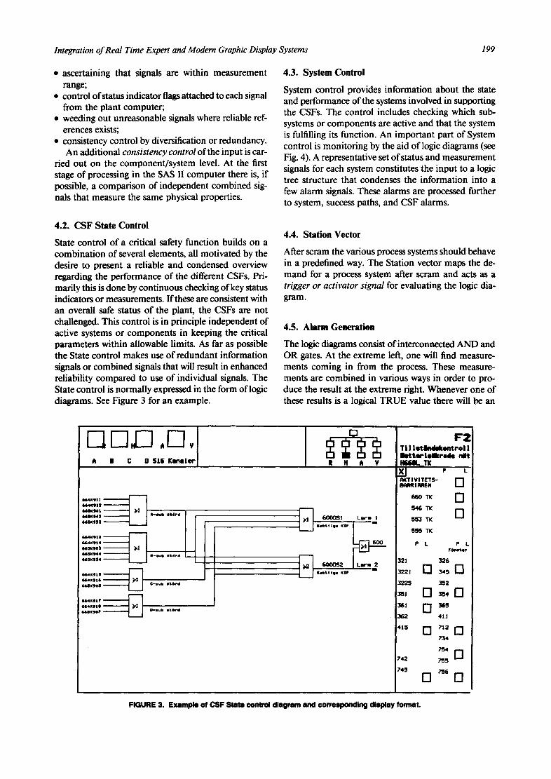
System control provides information about the state and performance of the systems involved in supporting the CSFs. The control includes checking which sub- systems or components are active and that the system is fulfilling its function. An important part of System control is monitoring by the aid of logic diagrams (see Fig. 4). A representative set of status and measurement signals for each system constitutes the input to a logic tree structure that condenses the information into a few alarm signals. These alarms are processed further to system, success paths, and CSF alarms.
4.2. CSF State Control
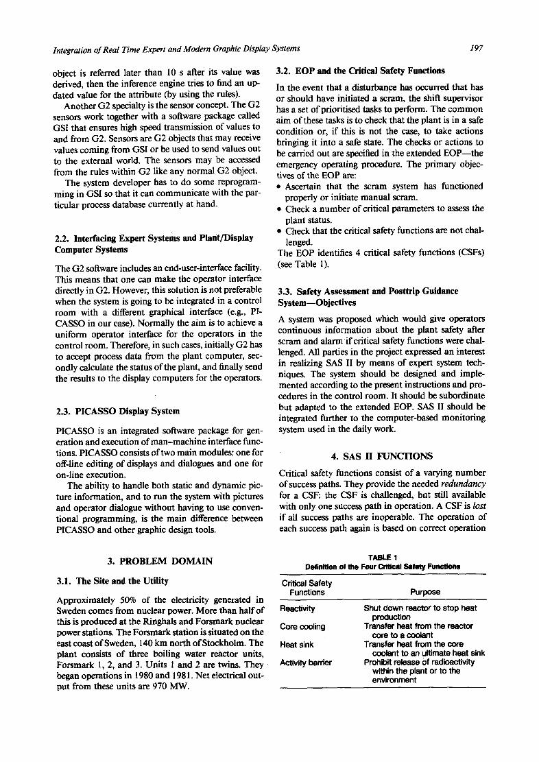
State control of a critical safety function builds on a combination of several elements, all motivated by the desire to present a reliable and condensed overview regarding the performance of the different CSFs. Pri- marily this is done by continuous checking of key status indicators or measurements. If these are consistent with an overall safe status of the plant, the CSFs are not challenged. This control is in principle independent of active systems or components in keeping the critical parameters within allowable limits. As far as possible the State control makes use of redundant information signals or combined signals that will result in enhanced reliability compared to use of individual signals. The State control is normally expressed in the form of logic diagrams. See Figure 3 for an example.
4.4. Station Vector
After scram the various process systems should behave in a predefined way. The Station vector maps the de- mand for a process system after scram and acts as a trigger or activator signal for evaluating the logic dia- gram.
4.5. Alarm Generation
The logic diagrams consist of interconnected AND and OR gates. At the extreme left, one will find measure- ments coming in from the process. These measure- ments are combined in various ways in order to pro- duce the result at the extreme right. Whenever one of these results is a logical TRUE value there will be an
i I I C D SlI KInmler
S64NgIt ! l l IK | J J 641K101 ~1 66SKgd3 ~ I t e r e 64~KeS3 !
664Kg$3 i'
~sxw,) ),J 6614(944 I-sub It4Pd 46SKI54 i ,
664KIIS 664K916
664K117 G64KIII 64kSKgO? P g u b i t 6 r d
IF2
t N It V
- ~ 6000S1 larm I i
88mtl IjI KIIF
flit I Oil KIP
Ti 1 let i indek~trol i I e t t er i eikrade nit HSSSL_T[
~ e L RK"I'IVI TETS- [ ] BqRRI ~tER
660 TK [ ]
546 TK D
553 TK
5~5~ TK
P k P L FOewte~
321 328
3221 G 345 [ ]
3225 352
362 4J|
734
742 ~ 5
749 ;~6 [] []
FIGURE 3. Example of CSF State control diagram and corresponding display format.
200 F. ~wre and S. Nilsen
5 I--l.r-1 ,r-l, A B C O 516 g a n a l e r
tz.,10s S l 6 K I
(I.S 4 KIlt 3~ ( 426V
~ 2 7 P I eO ~ ] 327¥102 eO I 127'wo? *s ~ ~'J' r31v I I I s 733K401 L3 - - ._~ 327g30 | ( 20kg /$
6 5 4 K t 3 6 <425v 327P2 eO
327V202 Ob 32~V207 IS - - PJ
733V112 733K402 L3
327K302 ~20kg /$
lSqK131 ' <425V ' -- I i 327P3 *O
327V302 tb 327V307 os ~
~ ' 33V113 $ ~ i 733K403 1.3 i
321K303 <20k9 /1
654K838 (4~5V
32~V402 tO ~ 4
I t 2~V407 q)$ ~ pJ ?33Vt 14 1 - -
7331{604 L3
327K304 (20kg /s
L_.[~ 327DR13 I.,
"--~] 327DR 12 I .
, .
- [ ~ 327DB12 ' I n
~ [-~ 327DC13
- ~ 3270C 12
[~ 327DD13 I .
327D012 I .
327DR2
_ ~ 327DR3 Ol&ker ,nFo
I I . . ~ 327DB2
Ej , d ~ , t t
. ~ 327083 0 l i V e r ,mFo
. _ ~ 322DE2 Ej , dr ,~ t
. _ ~ 327DC3 OE~ker , n f o
. . ~ 32?DD2
_ ~ 32?003 Os~e~ ;mFo
R H A V
m I
m
l i
I I t
y I I ~,
I -
I -
t
I -
70-01-01 o2:o3:3e I : ' 2 Logik 1 Systu 327 H327L& X J P L H#,RD- KYLNIHG [ ]
TK [ ] 211 TK 314 TK []
650 TK []
EGO TK
P L PL
314 [ ' - - ] 3 2 7
3J4R 327R [ ] $14B [ ] 327B [ ]
321 D327C 322 327D [ ] 323 [ ] 327E 323R 327F [ ] 323B [ ] 411 [ ] 323C [ ] 415 Aktlvl tet 415
FIGURE 4. Example of System control logic diagram and corresponding display format.
alarm associated with the corresponding critical func- tion.
5. SAS 11 M A N - M A C H I N E INTERFACE
A retrofitting of the color display system for the control room operators is in progress at Forsmark Units 1 and 2. The hardware consist of Ethernet connected engi- neering workstations from Hewlett Packard with high resolution color graphic interface for the operators. The color graphic tool-box PICASSO was chosen as display system software. It was also decided that PICASSO should be used for the display system functions of SAS II. The operators at Forsmark 2 will therefore get an integrated system consisting of the basic supervisory and the posttrip guidance system.
5.1. User Interaction Principles
To simplify user interaction a few simple principles have been used throughout SAS II for information pre- sentation and user interaction: • Each display is organized in the same way. It consists
of seven fixed fields or windows (see Figs. 3 and 4). This is important since the end-user then can apply the same visual search strategy in all situations.
• The content of five windows are controlled by the system, the two largest windows can be changed by the user.
• A trackerball with an addressing key is used for the interaction. All interaction between the system and the user is carded out with the trackerball.
• At any location in SAS II any other picture in the system can be reached by a maximum of two inter- actional steps, that is, with one trackerball move and one "click" on the trackerball addressing button for each step.
• All addressing spots in SAS II are represented by squares or rectangles. They appear in almost all the fields on the screen.
• Some addressing spots can be used to remove a win- dow or field on the screen. These are also squares or rectangles, but they have a cross within the frame.
• A signal can be followed through several logic display formats through direct addressing of spots in the logic diagrams.
5.2. Information Presentation Principles
The principles are based on redundancy in display and conformity in symbols and colors: • Redundant information transmission: When using
colors for transmitting information, these are not the only carders of information but they are used in re- dundancy with other information carders. For ex- ample, when a valve is moved from an open to a closed position, the valve changes color from that of the media passing through the valve (e.g., water) to

Integration of Real Time Expert and Modern Graphic Display Systems 201
a white contour of the valve symbol. The two parts of the valve symbol are separated.
• Conformity in symbols and colors: When using sym- bols and colors in process mimic display formats and for components, the same symbols and colors are used as in Forsmark 2's own symbol population (drawings and control board mimics).
• Flashing (red) is used only for attracting attention to the most important information at the moment. In SAS II it is used only for a nonconfirmed alarm of a degraded critical safety function.
6. EXPERIENCES APPLYING G2 FOR THE SAS II PROJECT
6.1. The Applicability of the G2 Tool
The first question to be treated in this section is how easy it was to do the implementation in G2. The ap- plication is rather straightforward: in short, it is to compute the state of some logic diagram. The logic diagram consists of gates (AND-, OR-, NOT-, etc.) connected in various ways.
In our implementation we implemented the logic gates as general data objects. These data objects were connected by using the connection facility of the G2 system itself. Once a library of various gates had been constructed, we constructed the diagrams by making instances of the graphical symbols from the library of gates. The symbols were placed in workspaces, and then connected by drawing lines between them.
6.1.1. The Practicality of Creating Dataobjects. Cre- ating data objects was a rather straightforward but te- dious job to do. Even though the menu-driven system of G2 is very suitable for a novice programmer, it be- comes rather awkward to use when proficiency in- creases. In order to make one object and place it in a workspace, there are a lot of menus to select from, and a lot of mouse clicks to do.
It is possible to shorten the sequence of menu se- lections somewhat by defining an appropriate user mode. For instance, it is possible to define a user mode which will effectuate certain actions whenever a par- ticular kind of object is clicked. For instance this could be bringing up the table of attributes. However, the set of actions which can be effectuated this way are very restricted, so the usefulness ofthis feature is rather lim- ited. For example, it is not possible to define a mode for filling in attribute values. The tell-and-ask facility of KEE is a much more flexible tool in this respect.
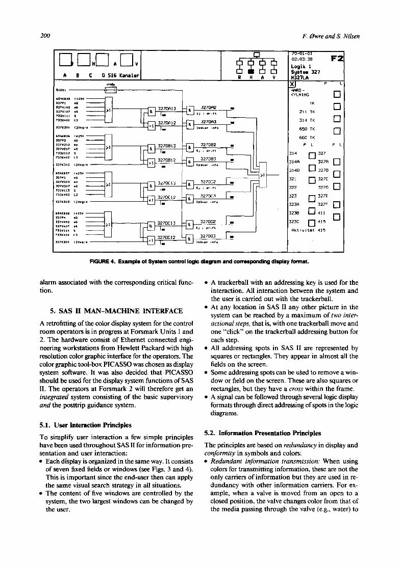
6.1.2. The Use of Class Hierarchies. The various classes of objects in the SAS implementation are struc- tured in a class hierarchy., Between any twO classes there can be a parent-child relationship. All the attributes of the parent are also included in the child.
One very high level class is called logic-unit. On the next level in the hierarchy there is, for instance, gates. Below gates there is, for instance, "exactly-n-of-m" which is supposed to be the root class of every gate producing true if and only if exactly n ofm inputs are true. Typical children to the "exactly-n-of-m" class are the AND-gate and the exclusive-OR (see Fig. 5).
Not every class in the hierarchy is supposed to be used for instantiating objects. The high level classes are most often used to give a general description of the lower level classes. This is done by specifying both a set of attributes and a set of associated rules.
Take the example of the class gate. In the set of attributes for this class there is specified one attribute named gate-output. This means that every object cre- ated on the basis of a subtype of this gate will have this attribute in its set of attributes.
6.1.3. Making Rules. Another very important facility related to the class hierarchy is generic rule objects. It is possible to apply rules on every object belonging to a certain class, for example,
for every gate i f . . . .
This rule is applied to every object of type gate and every object of any class which is a subclass of gate.
This structuring of the objects into a class hierarchy proved to be a very useful feature for implementing the SAS system. It probably facilitated the implemen- tation work a lot. However, this type of object-oriented programming facilities is not unique for the G2 system, and similar constructions can be found in many other programming environments.
6.1.4. Controlling the Firing of Rules. Some words have to be said concerning the possibilities to control the firing of the rules. For the more advanced ES shells there are usually mechanisms for controlling when and how rules should be fired, for example, meta rules.
During the SAS implementation we used some of these meta rules. Two of the most important categories of rules are the forwardtrace rules and the backtrace rules. The forwardtrace rules are mainly used to set the gate-output attribute of the gates. The backtrace rules are mainly used to set an attribute, "alarm-con- nected," which indicates whether the true output of the gate is one of the reasons for an alarm. In other words, the color of the output line is red if and only if the alarm-connected attribute is set to true.
The working strategy of the system is to run the forwardtrace rules according to the following meta rule:
for any gate G 1 connected at an output of any logic-unit G2
whenever the gate output of G2 receives a value then invoke forwardtrace rules for G 1.
202
Ibulmd : ~ of July 1990
F. Owre and S. Nilsen
|OBJECT- t
PLAIN- RJIM OF~lIP&¢ F..
3 I m . ~ w ( . ,~ | 0 M.INTE RFACF.-CLAgS-
A890CIAT E0- 8'VgT [ ~
ItOO,c.um. I
~ INFUT.CIOflNECTION-
OlffE- i TiME-DEUW- 9ET.llEgE'T- 0 &T E-
~ A mTll U L'T IC,- ~l~41TA lIT-
UEAN-UNff-
iNPUT.UNIT- i,~m.mu~,c.U,~T. | '1' ~, | ¢oueMmo~ /
: PE~ENTAOF..DIFF.
/ | ANOLUTT.-DiF F. UNIT-
FIGURE S. Class hierarchy for SASH knowledge base,
! aT.UmT.R-0~W ] | t-tEm-~T(- | AIiO-OAT£-
~ 1.0F-]- . IPj~. 4"'M O" Q AT F'"
EX&I~'E L¥- H-OF- U- ~ ) - - - iENC LUSIVE-OR-
i ~ Z-mB-()~E- *-M0.OSTE.
~ . OR.O&TE. e-OII.OATE-
. ~ IIIO-O~OATE- &T-LEAST-I~Or-ki. ~ NUO~OI~,GtTE-
~ . HUOF.-i.OR-OATE. mvEm'~ ' - - - I l.on.oa'r(.
| kil~OE~
This rule ensures that all the effects of a changed output status of any gate are transmitted to all the gates con- nected to it. On the other hand, if there is no change in the output status of a gate, then the reevaluation of the logic diagram stops at that point.
The forwardtrace rules may be temporarily inter- rupted by the firing of backtrace rules. This happens whenever the gate output of a gate is set to true and some of the gates connected to it have an alarm con- nected attribute set to true. Then the following meta rule ensures that all the relevant preceding gates will have alarm-connected attributes set to true. whenever the alarm-connected of any logic unit LU
receives a value then invoke backtrace rules for every logic unit connected at an input of LU.
Please note two important features of these rules. They both use the graphical interconnections of the objects. They also use the very general object classes to reach a very wide class of objects.
6.2. Structuring and Accessing the Knowledge Base
The structuring of the knowledge base is not only a matter of defining an appropriate object type structure. It is also a matter of putting together the objects (i.e., gates) so that the knowledge base is readily accessible.
It is a question of how easy it is to get an overview of the complete knowledge base, and furthermore, a question of how easy it is to access the particular objects from that overview.
As was mentioned in section 2, all G2 objects are put in so called workspaces. Consequently, the com- plete knowledge base is distributed in several work- spaces. It is possible to establish workspace-subwork- space relationships between workspaces. This is done by defining particular types of objects having the ca- pability of taking up subworkspaces when clicked. The knowledge base constructor may then establish one particular top level workspace consisting of these kind of objects.
From this top level workspace it is then possible to access subworkspaces giving more detailed information on some part of the knowledge base. There is no limit to the depth of the hierarchical structure of workspaces. However, it is the responsibility ofthe knowledge base constructor to make the hierarchy by hand. This means that nothing is done automatically by the system in order to create and maintain this structure. Further- more, the structure is always strictly hierarchical, an organisation of the workspaces that is not optimal for all applications.
The construction of overviews and addressing fields can also be achieved in a somewhat different manner. When running the command "show on a workspace
Integration of Real Time Expert and Modern Graphic Display Systems 203
all workspaces," a temporary workspace is created with one object for each of the existing workspaces. These objects may be transferred to a permanent workspace prepared by the knowledge base constructor and edited in such a manner that the structure of the knowledge base is explicit. The reason for using these particular objects is that they have a menu option "go to original." Clicking on this menu option will then take the user from the overview workspace down to the particular workspace which he has clicked. This last solution has the advantage that it can be used for nonhierarchal solutions as well.
About the same effect can be achieved by using ac- tion buttons. However, this requires that the G2 in- ference mechanism has been started. Consequently it is not very practical to use this when developing the knowledge base.
There is yet another aspect of organising knowledge bases, namely the distribution of the knowledge base on several files. The idea behind such a strategy is that parts of knowledge bases often can be used in more than one application area. In particular this applies to object definitions and rules. There are two persons working on the G2 implementation of SAS-II. Even though they are working on different logic diagrams, they share the same library of object definitions and rules.
6=3. Accessing the Knowledge Base without Using Its Structure
Sometimes it is desirable to go through the database according to patterns which are different from the structure of the knowledge base. For instance, when developing the knowledge base, it is often desirable to go through objects of a certain kind in order to fill in some kind of attribute.
According to our experience, a very important fa- cility in this respect is the inspect facility. It is possible, at any stage in the development process to select a sub- set of the complete knowledge base and place references to those objects in a temporary workspace. The knowl- edge base constructor formulates the selection criteria. For instance, it would be possible to give the following command "show on a workspace every tank where inflow >_ 14." After the temporary workspace has been created, it is possible to go from the objects on this workspace to the corresponding original. When there is no longer any use for the references the temporary workspace is deleted.
6.4. Relations between Objects and Their Graphical Appearance
One very important principle of G2 is the one-to-one correspondence between the object and the graphical object in the workspace. This means that an object can
only be in one workspace at a time. This was not totally uncomplicated in our case. When making the logic diagrams, there is a need to draw connections from one logic diagram to another. This would have been possible if the output object of one workspace could have been made identical to the input object of another workspace. However, within the frames of G2, this is not possible. Even though objects are given the same name they are considered two different objects by G2.
Generally, if one needs to have several graphical objects corresponding to one and the same conceptual object, one has to make several G2 objects and tie them together by using rules. This was done in our appli- cation. Whenever the gate-output attribute of any out- put object is changed, one particular rule will transmit the new value to the gate-output attribute of the input object.
6.5. Getting Data into and out of SAS II
As mentioned previously, a very important feature of any real time expert system is the possibility of high speed transmission of data to and from the system. Since the requirements on time response usually are rather severe, there is no time to do the inputs to the system manually. In addition, any expert system should be notified as soon as a process variable changes, and as a consequence of this the input should be handled automatically by a computer and not manually by an operator.
The G2 system has been equipped with such facil- ities. Inside G2 certain objects called sensors may be created. These objects may both receive values from outside and be used for transmitting values out from the G2 system. Whenever a sensor is used, a library of C-routines is called from G2. This program package is called GSI. Some of the routines in this package have been tailored for the SAS II application.
There are certain common data structures within GSI that are accessed by the routines in question. By reading and setting these data structures the C-code is receiving values from and transmitting values to G2.
During our work with GSI we sometimes felt that these data structures were unnecessarily complicated. There are many tables, records, and pointers involved, and it is often a long chain of references to go through before the ultimate element can be reached.
6.6. Time Efficiency and Stability
Since the end product is not yet finished our experi- ences on this matter are somewhat restricted. In par- ticular this applies to the stability aspect. Up to now, about three quarters of the system has been put in op- eration and it has been tested out for some simple scenarios. The stability has been quite satisfactory, and we have not observed any sign of unpredictable be-
204 F. Owre and S. Nilsen
havior yet. However, it remains to be seen what hap- pens when the scenarios become longer and more elaborate.
The time efficiency has been a bit disappointing and we are currently looking for ways to improve it. We have done some simple measurements on the time consumed. The time required to transfer one single value from G2 to the display computer is well below l s. However, when introducing changes in G2 that affect many variables, the performance becomes poorer. Setting the scram signal will cause a consid- erable amount of data to be transferred to the display computers. The time required to transfer all the changes is presently about 20 s. However, it is not the very transmission that takes time. It is probably the G2 rule evaluation that accounts for the major part of the time, and we are currently checking to see whether the rule firing is done in an optimal way.
The computer used when doing the time measure- ments is a HP340 with 16 Mb internal memory. Target computer is a HP834 (RISC processor based) and our latest performance measurements indicates that the HP834 is about five times faster than the HP340.
6.7. Possible Shortcomings of G2
As mentioned earlier, the SAS II application is rather straightforward, and as such it does not put the G2 system to a very severe test. In a more sophisticated application than ours features may be needed that are missing today.
First and foremost among those is the absence of dynamically created objects. There is no possibility to have the system creating new objects, for instance, as a consequence of some rule. This means that the set of objects must remain a fixed set of objects once the inference engine of G2 has been started.
Another problem is that there seems to be no easy way to handle list structures. One possibility is to use special kinds of list-element objects with a set of attri- butes keeping next, previous, and list-element pointers. However, since the set of objects is a fixed one, this is a rather restrictive solution.
Furthermore, we have second thoughts about the restricted possibility of using algorithms in the context of G2. Even though it is possible to write meta rules in G2, there is no possibility to give totally algorithmic descriptions of the rule-firing strategy. The algorithmic element might also be needed in other contexts where foreign function calls (C and FORTRAN) might prove insufficient.
The absence of these facilities contrasts with the fa- cilities offered by the expert system shell KEE. KEE is more or less fully integrate~l with the LISP system. This means that any part of the expert system may be started from LISP, and that any part of the expert system may
call upon any LISP function. This flexibility is, how- ever, probably paid for by a poor and unpredictable time response.
New facilities will be included in the next version of G2 (version 2.0) which will take care of these short- comings. These facilities will probably not be as flexible as the very open interface between KEE and LISP, but nevertheless they might be adequate for the great ma- jority of applications.
7. SUMMARY AND CONCLUSIONS
The SAS II project is quite unique in the history of the Halden Project. It combines the knowledge and ex- perience of staff from plant operation, a state power board, a vendor, a licensing authority, and a research institute in a single project to develop and install an advanced operator support system in a nuclear plant control room. The project is organized and run ac- cording to the ways devised as good practice for suc- cessful control room installations: end-user involve- ment in design, prototyping, a strict quality assurance program, and a verification program at a simulator before a final validation study is carried out as a means to decide whether the system should be installed in the control room.
The use of advanced technology in hardware and software has not created any problems so far. On the contrary the involved operators are enthusiastic about the new possibilities offered by the PICASSO display system.
The end-user involvement in the design is believed to be crucial. Without their deep interest and efforts to bring over to the design group their knowledge and experience it would probably have been difficult to in- troduce this system at Forsmark.
The prototype demonstration arranged midway in the project was extremely useful. It served two pur- poses. First it uncovered design flaws which could be corrected at an early stage without too much rear- rangements. Second, the team was able to demonstrate the system and its intended dynamic behavior for an assembled group of shift supervisors from Forsmark. This demonstration was indeed successful in that all shift supervisors afterward expressed a belief in the usefulness of the system.
G2 has proven to be extremely useful in this type of system development. The editing, modification, and testing facility is very powerful. The clean interface with the external world through GSI has also been easy to use. There is still a question whether the speed and performance of the G2 solution is good enough for a control room installation. This cannot be answered before the whole system is ready for testing. The re- quirement is that G2 shall be able to do a complete

Integration o f Real Time Expert and Modern Graphic Display Systems 20S
analysis cycle every 10 s. However, so far the results are promising.
REFERENCES
Baker, S., Marshall, E.C., Reiersen, C., Smith, L., & Gaudio, P.J. (1988). The experimental evaluation of the Success Path Moni- toring System--Results and conclusions. HWR-224, OECD Hal- den Reactor Project, Halden, Norway.
Coreoran, W.R., Finnicum, D.J., Hubbard III, F.R., Musick, C.R., & Walzer, P.F. ( 1981 ). Nuclear power plant safety functions. Nu- clear Safety, 22(2), Mareh-April.
Felkel, L., Eisgruber, H., & Reiner, H. (1987, May). Main results of the RIS project. Paper presented at EHPG meeting, Stromstad, Sweden, OECD Halden Reactor Project, Halden, Norway.
Fukunishi, K., et al. (1984, June). A computeriz~ operation and guidance method for post-trip control of BWRs. Seminar on Di- agnosis of and response to abnormal occurrances at nuclear power plants, Dresden, GDR.
GENSYM (1988). Version 1.1 of the G2 User's Manual. Gensym Corp., 125 Cambridge Park Drive, Cambridge, MA.
Hollnagel, E., & Marshall, E.C. (1984). The experimental evaluation of the Critical Safety Function Monitoring System--Executive summary. HPR-312, OECD Halden Reactor Project, Halden, Norway.
KSU (1989). Summary of operating experiences at Swedish nuclear power plants 1989. Swedish Nuclear Technology and Safety Centre, Stockholm, Sweden.
Pettersen, G., Hornas, A., & Stork,s, R. (1989). PICASSO User Manual. HWR-244, OECD Halden Reactor Project, Halden, Norway.