Embed Size (px)
Citation preview

Issue 20th October 2006
Integration of BX600 SB9 Switches in Cisco Networks
Pages 47
Contents 1 Introduction 3 2 Switch Connectivity 4
2.1 Auto Negotiation 4 2.1.1 Introduction 4 2.1.2 Recommended Solution 4 2.1.3 Configuration 4
2.2 Port Aggregation 5 2.2.1 Introduction 5 2.2.2 Recommended Solution 5 2.2.3 Configuration 6
2.3 VLANs and Trunks 8 2.3.1 Introduction 8 2.3.2 Recommended Solution 8 2.3.3 Configuration 8
2.4 Spanning Tree Protocol 11 2.4.1 Introduction 11 2.4.2 Recommended Solution 15 2.4.3 Configuration with VLAN Trunks 15 2.4.4 Configuration without VLAN Trunks 20
2.5 Access Port and NIC Configuration 24 2.5.1 Introduction 24 2.5.2 Recommended solution 24 2.5.3 Configuration 25
2.6 Link State 31 2.6.1 Introduction 31 2.6.2 Recommended Solution 31 2.6.3 Configuration 31
3 Basic Multicast Services 32 3.1 Introduction 32 3.2 Recommended solution 32 3.3 Configuration 32
4 Switch Management 35 4.1 Logging and Synchronization 35
4.1.1 Introduction 35 4.1.2 Recommended Solution 35 4.1.3 Configuration of syslog and SNTP 35
4.2 SNMP 37 4.2.1 Introduction 37 4.2.2 Recommended Solution 37 4.2.3 Configuration of SNMP 37
4.3 Remote Console Access 38 4.3.1 Introduction 38 4.3.2 Recommended Solution 38 4.3.3 Configuration of SSH 38
4.4 Integration into Radius and TACACS+ 39 4.4.1 Introduction 39 4.4.2 Recommended Solution 39 4.4.3 Configuration of RADIUS 39 4.4.4 Configuration of TACACS 43
4.5 Cisco Discovery Protocol 46

Whitepaper Issue: 20th October 2006 PRIMERGY BX600 GbE Switch (six 1 Gbit, two 10 Gbit Ports) Layer 2/3/4 Switch Page 2 / 47
4.5.1 Introduction 46 4.5.2 Recommended Solution 46 4.5.3 Configuration of CDP 46
4.6 Port Monitoring 47 4.6.1 Introduction 47 4.6.2 Configuration of Port Monitoring 47
4.7 Further information in the Internet: 47

Whitepaper Issue: 20th October 2006 PRIMERGY BX600 GbE Switch (six 1 Gbit, two 10 Gbit Ports) Layer 2/3/4 Switch Page 3 / 47
1 Introduction Today most datacenter networks run with switches from a single vendor. Although most of the protocols used are standardized, there are a number of proprietary ones – especially redundancy and management protocols. Other features may be so individual that interoperability is possible but not simple. It is therefore sometimes a challenge to integrate switches from one vendor into a network that has been build using a different vendor. This paper is intended to guide the reader with the task of integrating BX600 SB9 switches into Cisco networks. A number of major aspects that are common to most datacenter networks are covered and have been tested in Fujitsu Siemens’ laboratories. All the features of Cisco switches mentioned in this paper have been tested with Catalyst 3560 and Catalyst 3750 series switches. The following Cisco IOS software was used for the integration tests:
Catalyst 3750 IOS 12.2(25)SEE1 Advanced IP Services Catalyst 3560 IOS 12.2(25)SEE1 Advanced IP Services
The PRIMERGY BX600 GbE switch is an integrated Gigabit Ethernet switch for use in the PRIMERGY BX600 chassis. Up to four switches can be installed, and each installed switch offers ten 1Gbit downlink ports to the midplane for connection to server blades. The PRIMERGY GbE switch comes in two variants as regards the external ports: one with six 1 Gbit uplink ports (RJ45), and one with six 1 Gbit uplink ports and two 10 Gbit uplink ports (XFP, CX4). The two 10 Gbit ports of the second variant can be connected by means of an XFP module and a CX4 cable. Layer 2/3/4 functionalities are supported. PRIMERGY BX600 GbE switch variant 1:
• Six 1 Gbit/s Ethernet RJ45 ports
PRIMERGY BX600 GbE switch variant 2:
• Six 1 Gbit/s Ethernet RJ45 ports • Two 10 Gbit/s Ethernet ports (XFP, CX4) • Infiniband cable 10m (10GBASE-CX4)
must be ordered separately • XFP multimode module (10GBASE-SR)
must be ordered separately

White Paper Issue: October 2006 Integration of BX600 SB9 Switches in Cisco Networks Page 4 / 47
2 Switch Connectivity 2.1 Auto Negotiation 2.1.1 Introduction The SB9 is equipped with at least six Gigabit Ethernet ports which are implemented as specified in the 1000BaseT standard. (Since ten Gigabit Ethernet is not usual in datacenters’ server access layer, the 10GBaseCX4 and XFP interfaces that are also available are not covered here.) These ports can be run with different data rates and different duplex settings comparable to Cisco Switches. Table 1 shows the possible combinations of a Cisco Switch and an SB9. Only the combinations marked green are viable: the combinations marked red are risky because they will lead to a duplex failure. SB9
Fix
Hal
f Dup
lex
10
Fix
Hal
f Dup
lex
100
Fix
Full
Dup
lex
10
Fix
Full
Dup
lex
100
Aut
o
Fix Half Duplex 10 Ok N/A BAD N/A Ok Fix Half Duplex 100 N/A Ok N/A BAD Ok Fix Full Duplex 10 N/A N/A Ok N/A BAD Fix Full Duplex 100 N/A BAD N/A Ok BAD Fix Full Duplex 1000 N/A N/A N/A N/A Ok C
isco
Sw
itch
Auto Ok Ok BAD BAD Ok Table 1 : Speed and Duplex Settings During the ports’ autonegotiation phase the flow control mechanism can also be negotiated. Switches are not the best location for buffering packets during congestion; this mechanism should therefore not be activated on links between switches but preferably between servers and switches. In this case the server would be able to buffer the packets if the switch were to detect congestion on the uplink. Since flow control depends very much on the server hardware and software, this issue is not covered in this paper. 2.1.2 Recommended Solution We recommend setting the ports on both sides to auto negotiation. In this setting the switches will negotiate their capabilities and will find the best possible setting. When connected to the usual 1000BaseT port of a Cisco switch using a crossover or straight thru 8 wire Cat5E, or (better) a patch cable, the SB9 will negotiate 1000 Mbit with full duplex. Flow control should be disabled between switches. 2.1.3 Configuration You set a port of the SB9 (e.g. 0/12) to auto negotiation and no flow control by entering the following commands in configuration mode:
interface 0/12 negotiate no storm-control flowcontrol exit Here is the corresponding Cisco configuration:
interface GigabitEthernet0/2 speed auto duplex auto flowcontrol receive off end

White Paper Issue: October 2006 Integration of BX600 SB9 Switches in Cisco Networks Page 5 / 47
2.2 Port Aggregation 2.2.1 Introduction You will usually need more than 1 Gbit when connecting an SB9 switch in a datacenter. In this case two or more links are set up to form a port-channel, also known as a Fast Ethernet Channel (FEC) or Gigabit Ethernet Channel (GEC) in Cisco networks. Figure 1 shows a typical uplink configuration for an SB9: One port-channel connects to Cisco switch A and a second one connects to Cisco switch B. Each port-channel is formed of two links running with 1000 Mbit in full duplex mode. The redundancy mechanisms between these links will be discussed later. In principle, port-channels can be configured statically or using a port aggregation protocol. Cisco supports LACP as specified in 802.3ad and their proprietary PagP, while the SB9 supports LACP as specified in 802.3ad. Using static or LACP dynamic configuration, you can form up to six GE links between the SB9 and one other switch.
Figure 1 : Typical uplink configuration for SB9 Table 2 shows the possible combinations of port-channel settings between SB9 and Cisco switches. The combinations marked red are very risky and would lead to networks loops.
SB9
No
Cha
nnel
LAC
P
Sta
tic
No channel OK OK !!! Active OK OK !!! Passive OK OK !!! C
isco
On !!! !!! OK Table 2 : Possible port-channel configurations So called “split channels”; where one channel from one switch is terminated at two other switches; are supported neither by the SB9 nor by Cisco switches. 2.2.2 Recommended Solution Although Cisco switches and SB9 both support LACP, and although this feature has been tested to be compatible between these devices, we recommend using static configured trunks. This is the best practice to minimize the risk of incompatibilities and misconfigurations. Caution: In order to avoid loops in the network, please be sure that the affected ports of a port-channel are shut
down during the configuration process. Generating loops in a datacenter network may cause serious network problems!

White Paper Issue: October 2006 Integration of BX600 SB9 Switches in Cisco Networks Page 6 / 47
2.2.3 Configuration The setup in Figure 1 would be configured in the following steps:
• Step 1: Shut down the affected ports to avoid loops • Step 2: Set up the port-channel • Step 3: Bring up the affected ports • Step 4: Verify the operation of the port-channels
Step 1: Shut down the affected ports to avoid loops
! SB9 interface range 0/11 – 0/14 shutdown exit
! Cisco A interface range Gi 0/1 – 2 shutdown end
! Cisco B interface range Gi 0/1 – 2 shutdown end Step 2: Set up the port-channel
! SB9 port-channel Po1 interface 1/1 exit port-channel Po2 interface 1/2 exit interface range 0/11 – 0/12 channel-group 1/1 exit interface 0/13 – 0/14 channel-group 1/2 exit interface 1/1 ! static configuration – no LACP staticcapability exit interface 1/2 ! static configuration – no LACP staticcapability exit end
! Cisco A interface Port-channel1 ! interface range Gi 0/1 - 2 channel-group 1 mode on end
! Cisco B interface Port-channel2 ! interface range Gi 0/1 - 2
White Paper Issue: October 2006 Integration of BX600 SB9 Switches in Cisco Networks Page 7 / 47
channel-group 2 mode on end Step 3: Bring up the affected ports
! SB9 interface range 0/11 – 0/14 no shutdown exit end
! Cisco A interface Po 1 no shutdown end
! Cisco B interface Po 2 no shutdown end Step 4: Verify the operation of the port-channels
! SB9 (SB9) #show port-channel Logical Interface Port-Channel Name Link State Mbr Ports Active Ports ----------------- ----------------- ---------- ---------- ------------ 1/1 Po1 Up 0/11,0/12 0/11,0/12 1/2 Po2 Up 0/13,0/14 0/13,0/14
! Cisco A Cisco-A#show etherchannel summary Flags: D - down P - in port-channel I - stand-alone s - suspended H - Hot-standby (LACP only) R - Layer3 S - Layer2 U - in use f - failed to allocate aggregator u - unsuitable for bundling w - waiting to be aggregated d - default port Number of channel-groups in use: 1 Number of aggregators: 1 Group Port-channel Protocol Ports ------+-------------+-----------+---------------------------------------------- 1 Po1(SU) - Gi0/1(P) Gi0/2(P)
! Cisco B Cisco-A#show etherchannel summary Flags: D - down P - in port-channel I - stand-alone s - suspended H - Hot-standby (LACP only) R - Layer3 S - Layer2 U - in use f - failed to allocate aggregator u - unsuitable for bundling w - waiting to be aggregated d - default port Number of channel-groups in use: 1 Number of aggregators: 1 Group Port-channel Protocol Ports ------+-------------+-----------+---------------------------------------------- 1 Po1(SU) - Gi0/1(P) Gi0/2(P)

White Paper Issue: October 2006 Integration of BX600 SB9 Switches in Cisco Networks Page 8 / 47
2.3 VLANs and Trunks 2.3.1 Introduction Most network administrators want to partition their network into multiple broadcast domains to provide better network stability and better information security. This is implemented using virtual LAN technology (VLANs) which provides multiple virtual LAN segments in one switched network domain as specified in the standard 802.1Q. A number of protocols have been developed to simplify the management of such VLANs. While Cisco uses its own proprietary VLAN Trunking Protocol (VTP), the IEEE describes the GARP VLAN Registration Protocol (GVRP) which has been implemented in the SB9.
Figure 2 : VLAN Trunk between SB9 and Cisco Switch When multiple switches are interconnected there is often a need to transport multiple VLANs over one line. This technique is called VLAN Trunking and is described in the IEEE standard 802.1Q and implemented in the SB9. Some older Cisco switches implement a proprietary and incompatible ISL, but all devices found in modern datacenters will support 802.1Q trunks. Figure 2 shows a typical setup between a Cisco and an SB9 switch, whereby a port-channel is combined with a VLAN trunk. It is important to know the role of the so-called native VLAN on an 802.1Q trunk. All the packets on the trunk are encapsulated in 802.1Q packets, which means that a header containing the VLAN number and certain other information is added to the packet before it is transported over the trunk. Only the packets of the native VLAN are untagged for a variety of reasons. In most installations, VLAN1 is configured as native VLAN which is used for a number of protocols, such as VTP, CDP, STP, etc. 2.3.2 Recommended Solution Cisco’s VTP and standard GVRP are not compatible. Since a VLAN registration protocol is useful only when applied to several switches within a switch domain, GVRP is not recommended in a Cisco environment. A number of features of the current version V 2.0 make it neither usual nor advisable to use VTP in datacenter networks:
• The design of the VTP server and client concept is extremely delicate: if you bring in a VTP client switch with a higher configuration version number than the rest of the network, all the switches will copy the VLAN database from this switch. This will be a disaster if the new switch has been used in a laboratory and one or more VLANs had been deleted in the meantime.
• Manual trunk configuration is very deterministic as to which VLAN is on which trunk. This will simplify troubleshooting. • Manual trunk configuration may help the administrator to set up a simple load sharing.
We therefore recommend using manual VLAN registration in a Cisco datacenter network. Since the SB9 does not support ISL, the only solution for VLAN trunks to Cisco switches is IEEE 802.1Q. When STP is used, which is the case for most of datacenters, it is necessary to use a native VLAN because the standard defines that BPDUs have to be transported untagged. (See also Spanning Tree) Cisco recommends not using VLAN 1 for anything productive. It therefore makes sense to configure the management IP address of the SB9 into another VLAN, but it is nevertheless important to have one native VLAN defined on the trunk. 2.3.3 Configuration You set up a VLAN trunk as shown in Figure 2 and our recommendations by performing the following steps:
• Step 1: Configure the port-channels • Step 2: Define the VLANs • Step 3: Configure VLAN trunk • Step 4: Verify the VLAN trunk

White Paper Issue: October 2006 Integration of BX600 SB9 Switches in Cisco Networks Page 9 / 47
Step 1: Configure the port-channels Please refer chapter 2.2 Step 2: Define the VLANs
! SB9 ! Configure the VLANs (VLAN 1 is default and can’t be configured vlan database vlan 10 vlan name 10 VLAN-10 vlan 20 vlan name 20 VLAN-20 exit
! Cisco-A ! Configure the VLANs (VLAN 1 is default and can’t be configured vlan 10 name VLAN-10 ! vlan 20 name VLAN-20 ! vlan 30 name VLAN-30 Step 3: Configure VLAN trunk
! SB9 ! Definition of the port-channel port-channel Po1 interface 1/1 exit interface 0/11 channel-group 1/1 exit interface 0/12 channel-group 1/1 exit ! Configure the interfaces for VLAN trunking ! interface range 0/11 – 0/12 ! the native vlan 1 is default and normally not displayed in configuration switchport native vlan 1 switchport allowed vlan add 10 switchport tagging 10 switchport allowed vlan add 20 switchport tagging 20 exit ! Configure the port-channel for VLAN trunking ! interface 1/1 staticcapability ! the native vlan 1 is default and normally not displayed in configuration switchport native vlan 1 switchport allowed vlan add 10 switchport tagging 10 switchport allowed vlan add 20 switchport tagging 20 exit
! Cisco-A interface Port-channel6 switchport trunk native vlan 1 switchport trunk encapsulation dot1q switchport mode trunk

White Paper Issue: October 2006 Integration of BX600 SB9 Switches in Cisco Networks Page 10 / 47
switchport allowed vlan 1,10,20 ! interface range GigabitEthernet0/1 - 2 ! the native vlan 1 is default and normally not displayed in configuration switchport trunk native vlan 1 switchport trunk allowed vlan 1,10,20 switchport trunk encapsulation dot1q switchport mode trunk channel-group 6 mode on ! Step 4: Verify the VLAN trunk
! SB9 (bx6-sb9-a) #show vlan VLAN ID VLAN Name VLAN Type Interface(s) ------- ----------------------------- ---------- ------------------------- 1 Default Default 0/4,0/5,0/6,0/7,0/8,0/9, 0/10,0/11,0/12,0/13,0/15,0/16, 1/1,1/2 10 VLAN-10 Static 0/1,0/11,0/12,0/13,0/14,0/15, 0/16,1/1,1/2 20 VLAN-20 Static 0/2,0/11,0/12,0/13,0/14,0/15, 0/16,1/1,1/2 (bx6-sb9-a) #show interface switchport 1/1 Port Acceptable Ingress Default Interface VLAN ID Frame Types Filtering GVRP Priority --------- ------- ------------ ----------- ------- -------- 1/1 1 Admit All Disable Disable 0 (bx6-sb9-a) #
! Cisco-A Cisco-A# show interface trunk Port Mode Encapsulation Status Native vlan Po1 on 802.1q trunking 1 Port Vlans allowed on trunk Po1 1,10,20 Port Vlans allowed and active in management domain Po1 1,10,20 Port Vlans in spanning tree forwarding state and not pruned Po1 1,10,20

White Paper Issue: October 2006 Integration of BX600 SB9 Switches in Cisco Networks Page 11 / 47
2.4 Spanning Tree Protocol 2.4.1 Introduction When the only standard for spanning tree protocols in LANs was STP, as specified in 802.1D, Cisco developed a number of proprietary protocol enhancements. Some of these were adopted into the RSTP standard but others were not. Cisco therefore also modified their RSTP implementation to be compatible with their enhanced STP. Table 3 shows all current STP implementations. STP 802.1D STP as specified in 802.1D. Slow convergence, does not
support multiple instances for VLAN trunks. SB9: conforms to the standard Cisco: supported only on access ports not on trunks.
RSTP 802.1w Rapid STP as specified in 802.1w. Fast convergence, does not support multiple instances for VLAN trunks.
SB9: conforms to the standard Cisco: supported only on access ports not on trunks.
MSTP 802.1s Multiple Instance STP as specified in 802.1s. Fast convergence, support multiple instances for VLAN trunks
SB9: conforms to the standard Cisco: conforms to the standard but not common in Cisco environments
PVST+ STP as specified in 802.1D with the following enhancements: • port-fast feature • uplink-fast feature • backbone-fast features • spanning tree for each VLAN
Fast convergence, compatible to 802.1D even on VLAN trunks.
Cisco: proprietary solution SB9: not supported yet
PVST Like PVST+ but supporting only ISL trunks Cisco: proprietary solution
RAPID-PVST RSTP as specified in 802.1w with the following enhancements: • spanning tree for each VLAN
Fast convergence, compatible to 802.1D even on VLAN trunks.
Cisco: proprietary solution SB9: not supported yet
Table 3 : Spanning tree protocol implementations When connecting switches without VLAN trunks, PVST+ and STP are compatible with RSTP and RAPID-PVST respectively without any problems. Other combinations are discussed in the following section.
Running ST P 802.1D with PVST+ on VLAN Trunks When running STP over VLAN trunks, MSTP is the only STP protocol implemented by Cisco that completely complies with the IEEE standard. This is unfortunately not usually used in datacenter networks, where PVST+ and RAPID-PVST are more common. Unlike 802.1D, in which only one STP instance is used to control the STP state of the trunk, PVST+ runs one STP instance per VLAN, sends BPDUs and maintains one STP state per VLAN on a trunk. In addition to this major deviation from the standard, Cisco added a number of minor changes, such as the port-fast, uplink-fast and backbone-fast features, which have only local effects and do not limit their interoperability. PVST+ is also compatible to STP as specified in 802.1D when there is a native VLAN on the trunk. Figure 3 shows a scenario in which two Cisco switches are running PVST+ and an SB9 is running STP as specified in 802.1D.
Figure 3 : Combining PVST+ and 802.1D Switch A is configured as root bridge, while switch B will take over the root role when A fails. Since switch A sends untagged BPDUs from VLAN 1 to Po1, the SB9 uses Po1 as root port. Po2 of SB9 will take on port role “alternate” and will be in the state “discarding” and will not send any BPDUs at this port. Switch B will therefore also set its port Po2 to “designated” and “forwarding”. The SB9 takes all decisions as indicated by the BPDUs in VLAN 1, and all other BPDUs will be ignored. It is

White Paper Issue: October 2006 Integration of BX600 SB9 Switches in Cisco Networks Page 12 / 47
therefore important that one native VLAN is defined at both VLAN trunks. Cisco recommends that this native VLAN should be the same for both trunks to the SB9. If the Po1 link or switch A itself fails, the SB9 will change the role of Po2 to “designated” and its state to “forwarding”, after going through the state “learning”. According to the standard this will lead to a failover time of approximately twice the forward delay, which in normal cases will be about 30 seconds. Depending of the size of the network this time can be reduced by tuning the STP timers, but this must be done very carefully in order to provide a stable network. Please refer the standard 802.1D or Cisco’s recommendations for timer tuning. When the SB9 is running 802.1D it supports features such as Cisco’s proprietary port-fast when the “spanning-tree edgeport” command is applied. This means that an access port will take on the state “forwarding” and will omit the states “listening” and “learning”. This is needed when PXE boot mechanisms are used.
Running PVST+ on VLAN Trunks while disabling STP at the SB9 When STP is disabled at the SB9 it bridges the BDPUs without any modifications. Figure 4 shows this scenario.
SB9STP disabled
Cisco Apriority 0 for all vlans
Po1
Po1
Po2
Po2
Po3 Po3
On all trunks:VLAN 1 nativeVLAN 10 taggedVLAN 20 tagged
Cisco Bpriority 4096 for all vlans
Alternate discarding
Root portforwarding
Designated portforwarding
Designated portforwarding
Figure 4 : PVST+ while STP is disabled at SB9 Since switch B receives the BPDUs of switch A, its port Po2 will get the role “alternate” and it will take on the state “discarding”. The SB9 will not be involved in any decisions while the topology is changing. If the link Po1 fails, switch B will not receive any BPDUs at Po2. After three times the “hello” interval, Po2 will initiate its change to the role “designated” and will subsequently take on the “forwarding” state. Since no STP is enabled at the SB9, all the switch’s ports will be enabled and forwarding as soon as they come up. Without STP timer tuning, worst-case failover times resulting from link or switch failures were found to be approximately 45 seconds.

White Paper Issue: October 2006 Integration of BX600 SB9 Switches in Cisco Networks Page 13 / 47
Rapid Spanning Tree The standard IEEE 802.1w (RSTP) defines only BPDUs in the native VLAN as implemented by the SB9. Cisco also enhanced RSTP to RAPID-PVST which is compatible to RSTP in a number of ways. Figure 5 shows this scenario.
Figure 5 : Combining RAPID-PVST and 802.1w All RSTP features are functioning for the native (in this example VLAN1). Since the SB9 implements the standard, and does not know about tagged BPDUs, RAPID-PVST has the same restrictions as PVST+. There is an additional problem due to the fact that RSTP generates a Topology Change Notification (TCN) only when changing a port to the state “designated”. If the Po1 link in Figure 5 fails, port Po1 of switch A will go down and will not generate a TCN as specified in 802.1w. SB9 will change the role of port Po2 to root port and its state to “forwarding” and will generate a TCN as specified in 802.1w on the native VLAN. This has the effect that the Cisco switches will flush their MAC address tables of VLAN 1 but not for the other VLANs.

White Paper Issue: October 2006 Integration of BX600 SB9 Switches in Cisco Networks Page 14 / 47
Figure 6 : Combining RAPID-PVST and 802.1w after failure of Po1 Figure 6 shows this scenario. When server 1 now wants to send data to server 2, switch B will send it to switch A via Po3 (as indicated by the MAC address table), which has no connection to the SB9 and will drop the packet. This will not change until either the MAC address table entry times out (after ~300 seconds) or the server SB9 sends a packet that has been seen by switch B, whichever happens first. This scenario shows that RSTP and RAPID-PVST are not compatible in this respect. A worst-case failover time of 300 sec will not be acceptable.
Running RAPID-PVST on VLAN Trunks while disabling STP at the SB9 When RAPID-PVST is running at the Cisco switches and STP is disabled at the SB9 we have almost the same scenario as above, where the Cisco switches were running STP and STP was disabled at the SB9. Figure 7 shows this scenario.
SB9STP disabled
Cisco Apriority 0 for all vlans
Po1
Po1
Po2
Po2
Po3 Po3
On all trunks:VLAN 1 nativeVLAN 10 taggedVLAN 20 tagged
Cisco Bpriority 4096 for all vlans
Alternate discarding
Root portforwarding
Designated portforwarding
Designated portforwarding
Figure 7 : RAPID-PVST while STP is disabled at SB9 When the Po1 link fails, the Po2 of switch B will stop receiving BPDUs. After three times the “hello” interval, the switch will change the state of port Po2 to “learning” and will then follow the normal state machine so that the convergence time is the same as with 802.1D. Since the RSTP cannot operate with the proposal/agreement mechanism on this link, root changes will also be relatively slow within all the VLANs that are running on the trunks to the SB9.

White Paper Issue: October 2006 Integration of BX600 SB9 Switches in Cisco Networks Page 15 / 47
2.4.2 Recommended Solution As discussed earlier, there are a number of different combinations of STP protocols that can be selected when integrating SB9 switches into Cisco networks. Although using MSTP between the Cisco and the SB9 would be the best solution, it will not be discussed further in this paper because MSTP is so very unusual in Cisco networks. If you were to run MSTP (802.1s) on the SB9 switches while using STP or RSTP at the Cisco switches, MSTP would fall back to RSTP and STP respectively. The resulting and possible solutions are shown in Table 4.
SB9 Switch 802.1D 802.1w No STP
PVST+ Ok* Ok Ok Cisco Switch RAPID-
PVST with restrictions (Problems with TCN)
with restrictions (Problems with TCN) Ok
Table 4 : Possible STP combinations when using VLAN Trunks * SB9 firmware >1.14 required The recommended solution when running STP over VLAN trunks between Cisco and SB9 switches is to disable STP completely at the SB9 and run the STP or RSTP protocol at the Cisco switches (see Figure 4 and Figure 7). When the SB9 is connected to Cisco switches without VLAN trunks, the preferred solution is RSTP, because this would lead to the shortest failover times. Caution: In order to avoid loops in the network, please be sure that the VLAN configuration on both uplinks is
the same. Misconfiguration may lead to unidirectional links and to network loops! Caution: There is a significant difference between disabling STP on the SB9 globally and for each interface: If STP is disabled for one interface BPDUs are neither sent nor bridged. This behavior may lead to
network loops. When STP is disabled globally BPDUs are bridged. This is needed in the recommended scenarios.
Caution: When running STP on an SB9 it is important to enable STP at all ports, especially when creating port-
channels: this is not the default and must be enabled manually. 2.4.3 Configuration with VLAN Trunks You set up the scenario shown in Figure 8 by performing the following steps:
• Step 1: Configure the switches • Step 2: Verify the configuration
SB9STP disabled
Cisco Apriority 0 for all vlans
Po1
Po1
Po2
Po2
Po3 Po3
On all trunks:VLAN 1 nativeVLAN 10 taggedVLAN 20 tagged
Cisco Bpriority 4096 for all vlans
Alternate discarding
Root portforwarding
Designated portforwarding
Designated portforwarding
Gi 0/1
Gi 0/1 Gi 0/2
Gi 0/1
0/11
0/12
0/13
0/14
Gi 0/23
Gi 0/24
Gi 0/23
Gi 0/24
Figure 8 : Configuration example RAPID-PVST while STP is disabled at SB9 Step 1: Configure the switches
! SB9 configuration ! ! Disable STP for the whole switch ! (This command is normally not displayed) no spanning-tree

White Paper Issue: October 2006 Integration of BX600 SB9 Switches in Cisco Networks Page 16 / 47
! Define the VLANs vlan database vlan 10 vlan name 10 VLAN-10 vlan 20 vlan name 20 VLAN-20 exit ! Definine the port-channels port-channel Po1 interface 1/1 exit interface 0/11 channel-group 1/1 exit interface 0/12 channel-group 1/1 exit port-channel Po2 interface 1/2 exit interface 0/13 channel-group 1/2 exit interface 0/14 channel-group 1/2 exit ! Configure the interfaces interface range 0/11 – 0/14 spanning-tree port mode switchport allowed vlan add 10 switchport tagging 10 switchport allowed vlan add 20 switchport tagging 20 exit interface 1/1 staticcapability spanning-tree port mode switchport allowed vlan add 10 switchport tagging 10 switchport allowed vlan add 20 switchport tagging 20 exit interface 1/2 staticcapability spanning-tree port mode switchport allowed vlan add 10 switchport tagging 10 switchport allowed vlan add 20 switchport tagging 20 exit end
! Cisco Switch A ! Enable and configure RSTP spanning-tree mode rapid-pvst spanning-tree vlan 1,10,20 priority 0 ! ! Timers are tuned. Please refer Cisco documentation before ! using this part of the configuration ! spanning-tree vlan 1,10,20 hello-time 1 spanning-tree vlan 1,10,20 forward-time 8 spanning-tree vlan 1,10,20 max-age 11 ! vlan 10

White Paper Issue: October 2006 Integration of BX600 SB9 Switches in Cisco Networks Page 17 / 47
name VLAN-10 ! vlan 20 name VLAN-20 ! Define the port-channels ! interface Port-channel1 switchport trunk encapsulation dot1q switchport mode trunk ! interface Port-channel3 switchport trunk encapsulation dot1q switchport mode trunk ! interface GigabitEthernet0/1 switchport trunk encapsulation dot1q switchport mode trunk channel-group 1 mode on ! interface GigabitEthernet0/2 switchport trunk encapsulation dot1q switchport mode trunk channel-group 1 mode on interface GigabitEthernet0/23 switchport trunk encapsulation dot1q switchport mode trunk channel-group 3 mode on ! interface GigabitEthernet0/24 switchport trunk encapsulation dot1q switchport mode trunk channel-group 3 mode on
! Cisco Switch B ! Enable and configure RSTP spanning-tree mode rapid-pvst spanning-tree vlan 1,10,20 priority 4096 ! ! Timers are tuned. Please refer Cisco documentation before ! using this part of the configuration ! spanning-tree vlan 1,10,20 hello-time 1 spanning-tree vlan 1,10,20 forward-time 8 spanning-tree vlan 1,10,20 max-age 11 ! vlan 10 name VLAN-10 ! vlan 20 name VLAN-20 ! Define the port-channels ! interface Port-channel2 switchport trunk encapsulation dot1q switchport mode trunk ! interface Port-channel3 switchport trunk encapsulation dot1q switchport mode trunk ! interface GigabitEthernet0/1 switchport trunk encapsulation dot1q switchport mode trunk channel-group 2 mode on ! interface GigabitEthernet0/2 switchport trunk encapsulation dot1q

White Paper Issue: October 2006 Integration of BX600 SB9 Switches in Cisco Networks Page 18 / 47
switchport mode trunk channel-group 2 mode on interface GigabitEthernet0/23 switchport trunk encapsulation dot1q switchport mode trunk channel-group 3 mode on ! interface GigabitEthernet0/24 switchport trunk encapsulation dot1q switchport mode trunk channel-group 3 mode on Step 2: Verify the configuration
! Check if STP is diabled @ SB9 ! (bx6-sb9-a) #show spanning-tree summary Spanning Tree Adminmode........... Disabled Spanning Tree Version............. IEEE 802.1d Configuration Name................ Default Configuration Revision Level...... 0 Configuration Digest Key.......... 0xac36177f50283cd4b83821d8ab26de62 Configuration Format Selector..... 0 No MST instances to display. ! Check port-channel configuration (bx6-sb9-a) #show port-channel all Port- Link Log. Channel Adm. Trap STP Mbr Port Port Intf Name Link Mode Mode Mode Type Ports Speed Active ------ --------------- ------ ---- ---- ------ ------- ------ --------- ------ 1/1 Po1 Up En. En. En. Static 0/11 Auto True 0/12 Auto True 1/2 Po2 Up En. En. En. Static 0/13 Auto True 0/14 Auto True ! Check the VLAN configuration (bx6-sb9-a) #show vlan VLAN ID VLAN Name VLAN Type Interface(s) ------- -------------------------------- ---------- ------------------------- 1 Default Default 0/4,0/5,0/6,0/10,0/15, 0/16,1/1,1/2 10 VLAN-10 Static 0/1,0/15,0/16,1/1,1/2 20 VLAN-20 Static 0/2,0/15,0/16,1/1,1/2 (bx6-sb9-a) #
! Check if RSTP state at Cisco Switch A ! Cisco-A#show spanning-tree VLAN0001 Spanning tree enabled protocol rstp Root ID Priority 1 Address 0017.9470.3200 This bridge is the root Hello Time 1 sec Max Age 11 sec Forward Delay 8 sec Bridge ID Priority 1 (priority 0 sys-id-ext 1) Address 0017.9470.3200 Hello Time 1 sec Max Age 11 sec Forward Delay 8 sec Aging Time 300 Interface Role Sts Cost Prio.Nbr Type ---------------- ---- --- --------- -------- --------------------------------

White Paper Issue: October 2006 Integration of BX600 SB9 Switches in Cisco Networks Page 19 / 47
Po1 Desg FWD 3 128.96 P2p Po3 Desg FWD 3 128.112 P2p VLAN0010 Spanning tree enabled protocol rstp Root ID Priority 10 Address 0017.9470.3200 This bridge is the root Hello Time 1 sec Max Age 11 sec Forward Delay 8 sec Bridge ID Priority 10 (priority 0 sys-id-ext 10) Address 0017.9470.3200 Hello Time 1 sec Max Age 11 sec Forward Delay 8 sec Aging Time 300 Interface Role Sts Cost Prio.Nbr Type ---------------- ---- --- --------- -------- -------------------------------- Po1 Desg FWD 3 128.96 P2p Po3 Desg FWD 3 128.112 P2p VLAN0020 Spanning tree enabled protocol rstp Root ID Priority 20 Address 0017.9470.3200 This bridge is the root Hello Time 1 sec Max Age 11 sec Forward Delay 8 sec Bridge ID Priority 20 (priority 0 sys-id-ext 20) Address 0017.9470.3200 Hello Time 1 sec Max Age 11 sec Forward Delay 8 sec Aging Time 300 Interface Role Sts Cost Prio.Nbr Type ---------------- ---- --- --------- -------- -------------------------------- Po1 Desg FWD 3 128.96 P2p Po3 Desg FWD 3 128.112 P2p
! Check if RSTP state at Cisco Switch B ! Cisco-B#show spanning-tree VLAN0001 Spanning tree enabled protocol rstp Root ID Priority 1 Address 0017.9470.3200 Cost 3 Port 616 (Port-channel3) Hello Time 1 sec Max Age 11 sec Forward Delay 8 sec Bridge ID Priority 4097 (priority 4096 sys-id-ext 1) Address 000f.247b.d080 Hello Time 1 sec Max Age 11 sec Forward Delay 8 sec Aging Time 300 Interface Role Sts Cost Prio.Nbr Type ---------------- ---- --- --------- -------- -------------------------------- Po2 Altn BLK 3 128.640 P2p Po3 Root FWD 3 128.616 P2p VLAN0010 Spanning tree enabled protocol rstp Root ID Priority 10 Address 0017.9470.3200 Cost 3 Port 616 (Port-channel3) Hello Time 1 sec Max Age 11 sec Forward Delay 8 sec Bridge ID Priority 4106 (priority 4096 sys-id-ext 10) Address 000f.247b.d080
White Paper Issue: October 2006 Integration of BX600 SB9 Switches in Cisco Networks Page 20 / 47
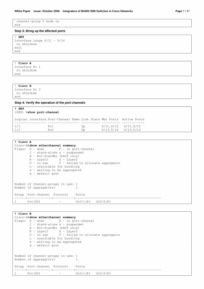
Hello Time 1 sec Max Age 11 sec Forward Delay 8 sec Aging Time 300 Interface Role Sts Cost Prio.Nbr Type ---------------- ---- --- --------- -------- -------------------------------- Po2 Altn BLK 3 128.640 P2p Po3 Root FWD 3 128.616 P2p VLAN0020 Spanning tree enabled protocol rstp Root ID Priority 20 Address 0017.9470.3200 Cost 3 Port 616 (Port-channel3) Hello Time 1 sec Max Age 11 sec Forward Delay 8 sec Bridge ID Priority 4116 (priority 4096 sys-id-ext 20) Address 000f.247b.d080 Hello Time 1 sec Max Age 11 sec Forward Delay 8 sec Aging Time 300 Interface Role Sts Cost Prio.Nbr Type ---------------- ---- --- --------- -------- -------------------------------- Po2 Altn BLK 3 128.640 P2p Po3 Root FWD 3 128.616 P2p 2.4.4 Configuration without VLAN Trunks You set up the scenario shown in Figure 8 by performing the following steps:
• Step 1: Configure the switches • Step 2: Verify the configuration
SB9RSTP enabled
Cisco Apriority 0 for all vlans
Po1
Po1
Po2
Po2
Po3 Po3
No Trunks
Cisco Bpriority 4096 for all vlans
Alternate discarding
Root portforwarding
Designated portforwarding
Designated portforwarding
Gi 0/1
Gi 0/1 Gi 0/2
Gi 0/1
0/11
0/12
0/13
0/14
Gi 0/23
Gi 0/24
Gi 0/23
Gi 0/24
Figure 9 : Configuration example RSTP without VLAN trunks Step 1: Configure the switches
! SB9 configuration ! ! Enable RSTP for the whole switch spanning-tree spanning-tree mode rstp ! Definine the port-channels port-channel Po1 interface 1/1 exit interface 0/11 channel-group 1/1 exit interface 0/12

White Paper Issue: October 2006 Integration of BX600 SB9 Switches in Cisco Networks Page 21 / 47
channel-group 1/1 exit port-channel Po2 interface 1/2 exit interface 0/13 channel-group 1/2 exit interface 0/14 channel-group 1/2 exit ! Configure the interfaces interface range 0/1 – 0/10 spanning-tree edgeport spanning-tree port mode interface range 0/11 – 0/14 spanning-tree port mode exit interface 1/1 staticcapability spanning-tree port mode exit interface 1/2 staticcapability spanning-tree port mode exit end
! Cisco Switch A ! Enable and configure RSTP spanning-tree mode rapid-pvst spanning-tree vlan 1 priority 0 ! ! Timers are tuned. Please refer Cisco documentation before ! using this part of the configuration ! spanning-tree vlan 1 hello-time 1 spanning-tree vlan 1 forward-time 8 spanning-tree vlan 1 max-age 11 ! ! Define the port-channels ! interface Port-channel1 ! These commands are default and normally not displayed switchport mode access switchport access vlan 1 ! interface Port-channel3 ! These commands are default and normally not displayed switchport mode access switchport access vlan 1 ! interface range GigabitEthernet0/1 - 2 ! These commands are default and normally not displayed switchport mode access switchport access vlan 1 channel-group 1 mode on ! interface range GigabitEthernet0/23 - 24 ! These commands are default and normally not displayed switchport mode access switchport access vlan 1 channel-group 3 mode on
! Cisco Switch B

White Paper Issue: October 2006 Integration of BX600 SB9 Switches in Cisco Networks Page 22 / 47
! Enable and configure RSTP spanning-tree mode rapid-pvst spanning-tree vlan 1 priority 0 ! ! Timers are tuned. Please refer Cisco documentation before ! using this part of the configuration ! spanning-tree vlan 1 hello-time 1 spanning-tree vlan 1 forward-time 8 spanning-tree vlan 1 max-age 11 ! ! Define the port-channels ! interface Port-channel2 ! These commands are default and normally not displayed switchport mode access switchport access vlan 1 ! interface Port-channel3 ! These commands are default and normally not displayed switchport mode access switchport access vlan 1 ! Interface range GigabitEthernet0/1 - 2 ! These commands are default and normally not displayed switchport mode access switchport access vlan 1 channel-group 2 mode on ! interface range GigabitEthernet0/23 - 24 ! These commands are default and normally not displayed switchport mode access switchport access vlan 1 channel-group 3 mode on Step 2: Verify the configuration
! Check if RSTP is enbled @ SB9 ! (bx6-sb9-a) #show spanning-tree summary Spanning Tree Adminmode........... Enabled Spanning Tree Version............. IEEE 802.1w Configuration Name................ Default Configuration Revision Level...... 0 Configuration Digest Key.......... 0xac36177f50283cd4b83821d8ab26de62 Configuration Format Selector..... 0 No MST instances to display. ! Check port-channel configuration (bx6-sb9-a) #show port-channel all Port- Link Log. Channel Adm. Trap STP Mbr Port Port Intf Name Link Mode Mode Mode Type Ports Speed Active ------ --------------- ------ ---- ---- ------ ------- ------ --------- ------ 1/1 Po1 Up En. En. En. Static 0/11 Auto True 0/12 Auto True 1/2 Po2 Up En. En. En. Static 0/13 Auto True 0/14 Auto True ! Check the RSTP State (bx6-sb9-a) #show spanning-tree mst port summary 0 all STP STP Port Interface Mode Type State Role --------- -------- ------- ----------------- ---------- 0/1 Enabled Forwarding Designated 0/2 Enabled Forwarding Designated 0/3 Enabled Disabled Disabled 0/4 Enabled Forwarding Designated

White Paper Issue: October 2006 Integration of BX600 SB9 Switches in Cisco Networks Page 23 / 47
0/5 Enabled Disabled Disabled 0/6 Enabled Disabled Disabled 0/7 Enabled Disabled Disabled 0/8 Enabled Disabled Disabled 0/9 Enabled Disabled Disabled 0/10 Enabled Disabled Disabled 0/11 Enabled PC Mbr Manual forwarding Disabled 0/12 Enabled PC Mbr Manual forwarding Disabled 0/13 Enabled PC Mbr Manual forwarding Disabled 0/14 Enabled PC Mbr Manual forwarding Disabled 0/15 Enabled Disabled Disabled STP STP Port Interface Mode Type State Role --------- -------- ------- ----------------- ---------- 0/16 Enabled Disabled Disabled 1/1 Enabled Forwarding Root 1/2 Enabled Discarding Alternate
! Check if RSTP state at Cisco Switch A ! Cisco-A#show spanning-tree VLAN0001 Spanning tree enabled protocol rstp Root ID Priority 1 Address 0017.9470.3200 This bridge is the root Hello Time 1 sec Max Age 11 sec Forward Delay 8 sec Bridge ID Priority 1 (priority 0 sys-id-ext 1) Address 0017.9470.3200 Hello Time 1 sec Max Age 11 sec Forward Delay 8 sec Aging Time 300 Interface Role Sts Cost Prio.Nbr Type ---------------- ---- --- --------- -------- -------------------------------- Po1 Desg FWD 3 128.96 P2p Po3 Desg FWD 3 128.112 P2p
! Check if RSTP state at Cisco Switch B ! Cisco-B#show spanning-tree VLAN0001 Spanning tree enabled protocol rstp Root ID Priority 1 Address 0017.9470.3200 Cost 3 Port 616 (Port-channel3) Hello Time 1 sec Max Age 11 sec Forward Delay 8 sec Bridge ID Priority 4097 (priority 4096 sys-id-ext 1) Address 000f.247b.d080 Hello Time 1 sec Max Age 11 sec Forward Delay 8 sec Aging Time 300 Interface Role Sts Cost Prio.Nbr Type ---------------- ---- --- --------- -------- -------------------------------- Po2 Altn BLK 3 128.640 P2p Po3 Root FWD 3 128.616 P2p

White Paper Issue: October 2006 Integration of BX600 SB9 Switches in Cisco Networks Page 24 / 47
2.5 Access Port and NIC Configuration 2.5.1 Introduction In a typical setup, ports for server access are not configured as VLAN trunks but as normal access ports. Since the SB9 configuration differs slightly from the Cisco configuration, we show how to set up an access port of the SB9.
Figure 10 : BX600 port mapping To ensure high availability of the servers, most BX600 racks will be equipped with two SB9 switches. In this case each blade has one NIC port connected to the first SB9 and another port connected to the second SB9 switch (see also Figure 10). In order to provide a fast failover between these NIC ports, both switch ports must be configured identically and the NIC failover must be configured in the right way. 2.5.2 Recommended solution The failover mechanism depends on the NIC vendor. At the moment there are two different type of NICs used for CPU blades: Intel and Broadcom. For CPUs equipped with Broadcom NICs running Microsoft Windows there are in general two failover mechanisms available:
• Smart Load Balance and Failover (with and without Auto-Fallback) • Link Aggregation (802.3ad or FEC/GEC)
Since the two ports of the NIC are terminated on two different switches, link aggregation cannot be used for failover. SLB depends on the link state of the NIC. When the CPU comes up, the primary adapter will become active. If the corresponding switch fails and the link state goes down, the secondary adapter takes over. If the link state of the primary adapter comes back and “Auto-Fallback” is enabled, the primary adapter will become active again. Since the link state of the primary adapter may come up before the uplinks of the corresponding switches are forwarding, this may lead to an unnecessary network failure. We recommend using SLB without Auto-Fallback for CPU with Broadcom NICs running Microsoft Windows. Almost the same applies to CPUs equipped with Intel NICs running under Microsoft Windows. They provide some additional failover mechanisms:
• Adapter Fault Tolerance (AFT) • Adaptive Load Balancing (ALB) • Link Aggregation (Static or 802.3ad) • Switch Fault Tolerance (SFT)
Link aggregation cannot also be used with Intel adapters in a BX600 rack. AFT and ALB both define a primary adapter and will fallback automatically when the link comes back after a switch failure. This would lead to the same problem as Auto-Fallback on Broadcom NICs. If you configure SFT with no adapter priorities there will be no automatic fallback. This is the recommended setup for CPU Blades equipped with Intel NICs running Microsoft Windows. Failover times of under one second can be achieved by following our recommendations.

White Paper Issue: October 2006 Integration of BX600 SB9 Switches in Cisco Networks Page 25 / 47
2.5.3 Configuration The following sample configurations show how to set up the switches’ access ports and the NIC drivers in a typical setup as shown in Figure 11.
Figure 11 : Typical access port configuration The following steps are required to configure this scenario:
• Step 1: Configure the access ports of the switches • Step 2: Configure the Broadcom Adapter • Step 3: Configure the Inter Adapter
Step 1: Configure the access ports of the switches
! Configuration of bx6-sb9-a interface 0/1 ! This line is only needed if you are running STP on the switch spanning-tree edgeport ! Forbid all VLANs but the access VLAN switchport forbidden vlan add 1 switchport forbidden vlan add 20 ! Permit the access VLAN switchport allowed vlan add 10 ! Set the access VLAN as native VLAN switchport native vlan 10 exit interface 0/2 ! This line is only needed if you are running STP on the switch spanning-tree edgeport ! Forbid all VLANs but the access VLAN switchport forbidden vlan add 1 switchport forbidden vlan add 10 ! Permit the access VLAN switchport allowed vlan add 20 ! Set the access VLAN as native VLAN switchport native vlan 20 exit
! Configuration of bx6-sb9-b interface 0/1 ! This line is only needed if you are running STP on the switch spanning-tree edgeport ! Forbid all VLANs but the access VLAN switchport forbidden vlan add 1 switchport forbidden vlan add 20 ! Permit the access VLAN

White Paper Issue: October 2006 Integration of BX600 SB9 Switches in Cisco Networks Page 26 / 47
switchport allowed vlan add 10 ! Set the access VLAN as native VLAN switchport native vlan 10 exit ! This line is only needed if you are running STP on the switch spanning-tree edgeport ! Forbid all VLANs but the access VLAN switchport forbidden vlan add 1 switchport forbidden vlan add 10 ! Permit the access VLAN switchport allowed vlan add 20 ! Set the access VLAN as native VLAN switchport native vlan 20 exit Step 2: Configure the Broadcom NIC To configure the Broadcom NIC, start the “Broadcom Advanced Control Suite 2”.
This is the main window of the “Broadcom Advanced Control Suite 2”. Select the menu item “Tools->Create a Team”
Enter a name for the team and press “Next>”
White Paper Issue: October 2006 Integration of BX600 SB9 Switches in Cisco Networks Page 27 / 47
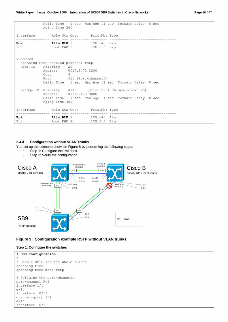
Select the first adapter as “Load Balance Member” and the second as “Standby Member” and press “Preview”.
Review the configuration and press “OK”
Press “Yes”
Press “OK”

White Paper Issue: October 2006 Integration of BX600 SB9 Switches in Cisco Networks Page 28 / 47
Step 3: Configure the Intel Adapter To configure the Intel NIC, open the “Local Area Connection Properties” for the first adapter.
Press ”Configure”
Select the “Teaming” tab

White Paper Issue: October 2006 Integration of BX600 SB9 Switches in Cisco Networks Page 29 / 47
Select "Team with other adapters" and Press "New Team"
Enter a name for the team and press "Next"
Check the desired adapters and press "Next"

White Paper Issue: October 2006 Integration of BX600 SB9 Switches in Cisco Networks Page 30 / 47
Select "Switch Fault Tolerance" and press “Next”
Press "Finish"

White Paper Issue: October 2006 Integration of BX600 SB9 Switches in Cisco Networks Page 31 / 47
2.6 Link State 2.6.1 Introduction BX600 Blade Servers are equipped with 2 independent LAN ports by default. LAN Port redundancy is realized by utilizing NIC management programs with LAN teaming functions such as ‘Broadcom BACS’, ‘Intel ProSETII’ and ‘Linux Channel Bonding’. However the server blade cannot detect a link down situation or a port failure situation timely if link failures occur on the uplink port(s) on SB9 Switch connected to the next higher level switches. In this case, it takes a long time (over 5-10 seconds) to perform a NIC failover via the teaming software of the server blade (it depends on polling period implemented in NIC management program). In order to realize a “rapid” fail-over of redundant blade server LAN ports, SB9 is able to shut down ports linked to server blades (internal ports) whenever an uplink port (external port) fails. If the upstream port is resumed to active state, the downstream ports will be enabled again.
Gi 0/1
0/11
SB9
Cisco external Ports
internal Ports
link state group
0/11 SB9detail
downlinks
uplinks
Figure 12 : Link State Group 2.6.2 Recommended Solution The SB9 provides a monitor task to see the link level of the upstream ports. If any upstream port fails, SB9 will disable the downstream ports belonging to the same Link State Group. This enables the LAN Teaming Software to detect the link failure and to switch the LAN port from failed one (Link down) to a working one in a short time. We recommend configuring link state groups for the considered ports in the customer configuration to improve failover behaviour 2.6.3 Configuration The following steps are necessary to set up a Link State Group:
• 1. Enable the Link State feature and create a Link State Group • 2. Configure the up- and downstream ports and enable the configured Link State Group • 3. Verify the configuration
Step 1: Configure a Link State Group
link state ! Enables the Link State admin mode link state group ! Creates a link state group Step 2: Configure the up- and downstream ports and enable the configured Link State Group
interface range 0/1 – 0/4 link state group 1 downstream ! Sets the downstream port(s) for a Link State Group (Port 1 to 4 in this example) exit interface 0/11 link state group 1 upstream ! Sets the monitored upstream port for a Link State Group exit link state group enable 1 ! Enables the configured Link State Group

White Paper Issue: October 2006 Integration of BX600 SB9 Switches in Cisco Networks Page 32 / 47
Step 3: Verify the configuration
show link state ! Shows information about configured Link State Groups
3 Basic Multicast Services 3.1 Introduction IP Multicast applications are common to many datacenter networks. At least the deployment software for the blade server often uses multicast to deploy multiple servers using one data stream. In most Cisco networks, the SB9 will act as a Layer 2 switch which has to perform IGMP snooping in order to avoid unnecessary multicast traffic at ports that are not interested in this traffic.
3.2 Recommended solution It is advisable to enable IGMP snooping over the whole broadcast domain and therefore at all switches. To get IGMP snooping running you will need one IGMP querier per VLAN. In most cases there will be a Layer 3 switch in each VLAN which is also the unicast router for that VLAN. We recommended you to configure this router for multicast routing and enable a IGMP querier in this way, because the multicast router will need the IGMP information anyway. At the SB9 and at all other L2 switches, you only need to enable IGMP snooping.
3.3 Configuration The following steps are necessary to set up IGMP snooping:
• 1. Enable multicast routing and IGMP at the layer 3 switch • 2. Enable IGMP snooping at all layer 2 switches • 3. Verify the configuration
1. Enable multicast routing and IGMP at the layer 3 switch
! Layer 3 Switch Configuration ! ============================ ! ! In this example PIM dense mode is activated since this is the ! most simple solution. In datacenter networks a more sophisticated solution ! should be used but multicast routing is not in the scope of this document. ! ip multicast-routing distributed ! interface Vlan1 ip address 10.222.0.1 255.0.0.0 ip pim dense-mode ! interface Vlan10 ip address 192.168.10.1 255.255.255.0 ip pim dense-mode ! interface Vlan20 ip address 192.168.20.1 255.255.255.0 ip pim dense-mode 2. Enable IGMP snooping at all Layer 2 switches
! Layer 2 Switch Configuration (Cisco) ! ! All these commands are enable by default and are not seen in the config normally ! ! Enable IGMP snooping global ip igmp snooping ! Enable IGMP snooping for VLANs ip igmp snooping vlan 1 ip igmp snooping vlan 10 ip igmp snooping vlan 20
! SB9 Switch Configuration ! ! Enable IGMP snooping global

White Paper Issue: October 2006 Integration of BX600 SB9 Switches in Cisco Networks Page 33 / 47
ip igmp snooping ! Enable IGMP snooping for VLANs vlan database set igmp 1 set igmp 10 set igmp 20 exit ! Enable IGMP snooping for ports interface 0/1 - 0/16 ip igmp snooping interfacemode exit interface 1/1 - 1/2 ip igmp snooping interfacemode exit 3. Verify the configuration
(bx6-sb9-b) #show ip igmp snooping Admin Mode..................................... Enable Multicast Control Frame Count.................. 89107 Interfaces Enabled for IGMP Snooping........... 0/1 0/2 0/3 0/4 0/5 0/6 0/7 0/8 0/9 0/10 0/11 0/12 0/13 0/14 0/15 0/16 1/1 1/2 Vlans enabled for IGMP snooping................ 1 10 20 ================================================================= (bx6-sb9-b) #show ip igmp snooping mrouter VLAN Type Memeber Port ====== ========= ========================================================= 1 Dynamic 1/1 10 Dynamic 1/1 20 Dynamic 1/1 ================================================================= (bx6-sb9-b) #show ip igmp snooping multicast VLAN MAC Addr Type Memeber Port ===== =================== ========= ========================================= 1 01:00:5e:00:01:18 Dynamic 1/1 1 01:00:5e:00:01:28 Dynamic 1/1 1 01:00:5e:00:01:3c Dynamic 1/1 1 01:00:5e:00:17:17 Dynamic 1/1 1 01:00:5e:7f:00:01 Dynamic 1/1,0/5 <====== 0/5 has joined 239.255.0.1 1 01:00:5e:7f:00:02 Dynamic 1/1,0/5 <====== 0/5 has joined 239.255.0.2 1 01:00:5e:7f:ff:fa Dynamic 1/1 1 01:00:5e:7f:ff:fe Dynamic 1/1 10 01:00:5e:7f:00:01 Dynamic 1/1,0/1 10 01:00:5e:7f:00:02 Dynamic 1/1,0/1

White Paper Issue: October 2006 Integration of BX600 SB9 Switches in Cisco Networks Page 34 / 47
20 01:00:5e:7f:00:01 Dynamic 1/1,0/2 20 01:00:5e:7f:00:02 Dynamic 1/1,0/2

White Paper Issue: October 2006 Integration of BX600 SB9 Switches in Cisco Networks Page 35 / 47
4 Switch Management 4.1 Logging and Synchronization 4.1.1 Introduction When there are problems in a network it is vital to log the events at all network devices. Since a data center network often consists of many network devices, a central logging server is used to collect the information from all components. Logging information is usually sent using the protocol syslog (RFC 3164), which is supported both by SB9 and Cisco switches. The server may be an UNIX system, in which a syslog daemon is usually distributed with the operating system, or a Windows system with a special syslog server installed. A syslog message includes a time stamp to enable administrators to correlate events, and it is therefore necessary to synchronize the time bases used by all the devices. The standards for this task are NTP and SNTP. NTP (Network Time Protocol) is a mechanism that ensures reliable synchronization between devices over IP networks, even where there is a high delay on the lines, such as when the synchronization is running over WAN links. When running in a LAN environment you can use a less complex protocol (SNTP, standing for simple NTP), which is compatible to NTP and can use a NTP server as time source. 4.1.2 Recommended Solution Since syslog is an unreliable protocol, we recommend that you also enable logging to memory at the SB9. The synchronization should be performed by configuring two NTP servers or using a NTP broadcast source, as specified in whichever standard is in use at the data center. 4.1.3 Configuration of syslog and SNTP The following steps are necessary to enable logging and SNTP
• Step 1a: Configure the SB9 for unicast SNTP • Step 1b: Alternatively configure the SB9 for broadcast SNTP • Step 2: Configure the SB9 for logging and syslog • Step 3: Test the configuration
Step 1a: Configure the SB9 for unicast SNTP
! SB9 unicast SNTP configuration ! ! Enable the SNTP client sntp client mode unicast ! ! Configure the NTP server sntp server 10.222.0.1 ipv4 sntp server 10.222.0.2 ipv4 ! Configure the time zone sntp clock timezone MEST 2 0 before-utc Step 1b: Configure the SB9 for broadcast SNTP
! SB9 broadcast SNTP configuration ! ! Enable the SNTP client in broadcast mode sntp client mode broadcast ! ! Configure the time zone sntp clock timezone MEST 2 0 before-utc Step 2: Configure the SB9 for logging and syslog
! SB9 logging configuration ! ! Enable logging into memory logging buffered ! ! Wrap the logging buffer when capacity is reached logging buffered wrapped ! ! Enable syslog logging syslog ! ! Send syslog messages to 10.222.0.21 port 514 (default) ! Include all messages upto debug severity logging host 10.222.0.21 514 debug !

White Paper Issue: October 2006 Integration of BX600 SB9 Switches in Cisco Networks Page 36 / 47
Step 3: Test the configuration When running in SNTP unicast mode, the output is as follows:
(bx6-sb9-a) #show sntp Last Update Time: AUG 21 13:34:59 2006 Last Unicast Attempt Time: AUG 21 13:34:59 2006 Last Attempt Status: Success Broadcast Count: 0 Time Zone : MEST 02:00 Before UTC (bx6-sb9-a) #show sntp client Client Supported Modes: unicast broadcast SNTP Version: 4 Port: 123 Client Mode: unicast Unicast Poll Interval: 6 , which mean 2^6 in seconds Poll Timeout (seconds): 5 Poll Retry: 1 (bx6-sb9-a) #show calendar Current Time : 8/21/2006 13:36:20 When running in STNP broadcast mode, the output is as follows:
(bx6-sb9-a) #show sntp client Client Supported Modes: unicast broadcast SNTP Version: 4 Port: 123 Client Mode: broadcast Broadcast Poll Interval: 6 , which mean 2^6 in seconds (bx6-sb9-a) #show sntp Last Update Time: AUG 21 13:55:16 2006 Last Unicast Attempt Time: AUG 21 13:40:22 2006 Last Attempt Status: Success Broadcast Count: 2 Time Zone : MEST 02:00 Before UTC (bx6-sb9-a) #show calendar Current Time : 8/21/2006 13:56:27 At the syslog server, entries may look like as follows:
17.08.2006 13:29 Kernel.Info 10.0.2.70 AUG 17 13:27:56 10.0.2.70-1 UNKN[199044152]: sntp_client.c(1679) 36 %% SNTP: system clock synchronized on THU AUG 17 13:27:56 2006 UTC 17.08.2006 13:31 Kernel.Notice 10.0.2.70 AUG 17 13:30:11 10.0.2.70-1 TRAPMGR[248845768]: traputil.c(703) 37 %% Link Up: Unit: 1 Slot: 0 Port: 11 17.08.2006 13:31 Kernel.Notice 10.0.2.70 AUG 17 13:30:11 10.0.2.70-1 TRAPMGR[248845768]: traputil.c(703) 38 %% Link Up: Unit: 1 Slot: 0 Port: 12 17.08.2006 13:31 Kernel.Notice 10.0.2.70 AUG 17 13:30:11 10.0.2.70-1 TRAPMGR[248845768]: traputil.c(703) 39 %% Link Up: Unit: 1 Slot: 1 Port: 1 17.08.2006 14:02 Kernel.Notice 10.0.2.70 AUG 17 14:01:23 10.0.2.70-1 TRAPMGR[248845768]: traputil.c(703) 48 %% Link Up: Unit: 1 Slot: 1 Port: 2 17.08.2006 14:02 Kernel.Notice 10.0.2.70 AUG 17 14:01:54 10.0.2.70-1 TRAPMGR[248845768]: traputil.c(703) 49 %% Link Down: Unit: 1 Slot: 0 Port: 14

White Paper Issue: October 2006 Integration of BX600 SB9 Switches in Cisco Networks Page 37 / 47
4.2 SNMP 4.2.1 Introduction In most enterprise networks, SNMP is used for monitoring of network components. The most common protocol versions are SNMPv1 and SNMPv2c, which are fully supported by the SB9. SNMPv3 is seldom used today. 4.2.2 Recommended Solution We recommend you to enable SNMPv1 and SNMPv2c at the SB9 and (for security reasons) to enable authentication for SNMPv3. 4.2.3 Configuration of SNMP The following steps are necessary in order to configure SNMP
• Step 1: Configure SNMP for SNMPv1 and SNMPv2c • Step 2: Configure SNMPv3 authentication • Step 3: Test the SNMP configuration using your favorite SNMP management tool
Step 1: Configure SNMP for SNMPv1 and SNMPv2c
! SNMP v1 and v2c setup for SB9 ! Configure the description, system name, contact and the location ! !System Description "FSC SwitchBlade" snmp-server sysname "bx6-sb9-a" snmp-server location "Team PCT" snmp-server contact "Test123" ! configure two snmp community strings (e.g. read and write) ! snmp-server community ro read snmp-server community rw write ! remove the default community strings no snmp-server community public no snmp-server community private ! configure the trap receiver ! ! … for SNMPv2c snmptrap MySNMPv2 10.222.0.20 ! … for SNMPv1 snmptrap MySNMPv1 10.222.0.20 snmpversion snmpv1 Step 2: Configure SNMPv3 authentication It is important to set the SNMPv3 authentication protocol to “MD5” for each configured user name, to ensure that nobody can access the switch using SNMPv3 without authentication. This can only be done using the web interface.

White Paper Issue: October 2006 Integration of BX600 SB9 Switches in Cisco Networks Page 38 / 47
Step 3: Test the SNMP configuration using your favorite SNMP management tool The following tests have been done using NET-SNMP with SNMPv2:
C:\>snmpwalk -v 2c -c read 10.0.1.70 system SNMPv2-MIB::sysDescr.0 = STRING: FSC SwitchBlade SNMPv2-MIB::sysObjectID.0 = OID: SNMPv2-SMI::enterprises.231 DISMAN-EVENT-MIB::sysUpTimeInstance = Timeticks: (26581200) 3 days, 1:50:12.00 SNMPv2-MIB::sysContact.0 = STRING: Test123 SNMPv2-MIB::sysName.0 = STRING: bx6-sb9-a SNMPv2-MIB::sysLocation.0 = STRING: Team PCT SNMPv2-MIB::sysServices.0 = INTEGER: 6 SNMPv2-MIB::sysORLastChange.0 = Timeticks: (500) 0:00:05.00 C:\>snmpget -v 2c -c write 10.0.1.70 sysContact.0 SNMPv2-MIB::sysContact.0 = STRING: Test123 C:\>snmpset -v 2c -c write 10.0.1.70 sysContact.0 s "SNMP v2c Write Test" SNMPv2-MIB::sysContact.0 = STRING: SNMP v2c Write Test C:\>snmpget -v 2c -c write 10.0.1.70 sysContact.0 SNMPv2-MIB::sysContact.0 = STRING: SNMP v2c Write Test C:\>snmpset -v 2c -c read 10.0.1.70 sysContact.0 s "SNMP v2c Read-Only Test" Error in packet. Reason: noAccess Failed object: SNMPv2-MIB::sysContact.0
4.3 Remote Console Access 4.3.1 Introduction In addition to the web interface, the SB9 supports three methods of accessing the command line interface:
• Console access using console redirection of the management blade • Telnet access • SSH access
During the initial setup, console redirection is the only possible way of accessing the switch. Access using telnet or SSH will subsequently be more convenient. 4.3.2 Recommended Solution Telnet is an unencrypted protocol, which means that not only the data but also the password is sent unencrypted over IP. For this reason most enterprise customers prefer not to use telnet. SSH encrypts not only the password but also the entire data traffic, and is the preferred protocol for remote console access. We recommend you to enable SSH and disable telnet access to the switch. 4.3.3 Configuration of SSH The following steps are necessary to enable SSH and disable telnet.
• Step 1: Configure the SB9 • Step 2: Test the login
Step 1: Configure the SB9
! SB9 ssh configuration ! ! Enable ssh ip ssh ! Set the procol version 2 ip ssh protocol 2 ! Disable telnet line vty no sessions exit Step 2: Test the login One of the popular SSH clients is “putty” which is distributed under license from MIT.
C:\> putty bx6-sb9-b login as: test-ro test-ro @bx6-sb9-b's password: (bx6-sb9-b) >

White Paper Issue: October 2006 Integration of BX600 SB9 Switches in Cisco Networks Page 39 / 47
4.4 Integration into Radius and TACACS+ 4.4.1 Introduction Radius and TACACS are protocols that can be used for authentication, authorization and accounting. Enterprises often use one of these protocols to authenticate administrative users of network components. The SB9 supports RADIUS and TACACS+ for the authentication of users which want to access the switch using the web interface, telnet or SSH. It also supports these protocols for 802.1X, but since this protocol is rarely used in datacenter networks this feature is not discussed here. 4.4.2 Recommended Solution In most Cisco networks a Cisco Secure ACS is used as TACACS+ and RADIUS server. The protocol should be selected in compliance with company policy, so both configurations are described here. 4.4.3 Configuration of RADIUS The following steps are necessary to integrate an SB9 into RADIUS authentication.
• 1. Prepare the ACS • 2. Configure the SB9 • 3. Test the login
Step 1: Prepare the ACS To prepare the ACS to be an authentication server for the SB9, log in to the web interface of the SB9 and perform the following configuration:
Add the device using the button “Add Entry”

White Paper Issue: October 2006 Integration of BX600 SB9 Switches in Cisco Networks Page 40 / 47
Enter the name and IP address of the switch. Use RADIUS IETF, enter the shared key and press “Submit + Restart”
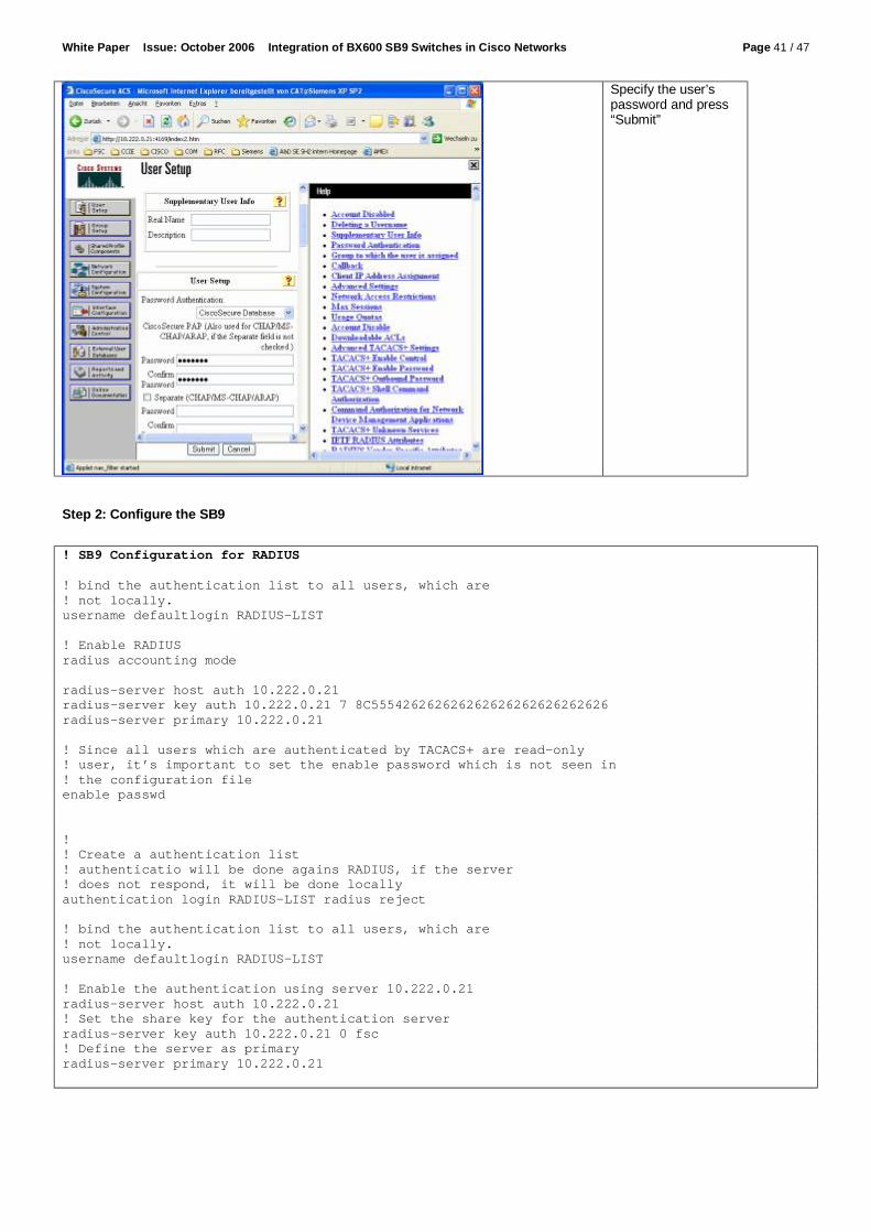
Add the users to the ACS database, e.g. the user “test-ro”
White Paper Issue: October 2006 Integration of BX600 SB9 Switches in Cisco Networks Page 41 / 47
Specify the user’s password and press “Submit”
Step 2: Configure the SB9
! SB9 Configuration for RADIUS ! bind the authentication list to all users, which are ! not locally. username defaultlogin RADIUS-LIST ! Enable RADIUS radius accounting mode radius-server host auth 10.222.0.21 radius-server key auth 10.222.0.21 7 8C555426262626262626262626262626 radius-server primary 10.222.0.21 ! Since all users which are authenticated by TACACS+ are read-only ! user, it’s important to set the enable password which is not seen in ! the configuration file enable passwd ! ! Create a authentication list ! authenticatio will be done agains RADIUS, if the server ! does not respond, it will be done locally authentication login RADIUS-LIST radius reject ! bind the authentication list to all users, which are ! not locally. username defaultlogin RADIUS-LIST ! Enable the authentication using server 10.222.0.21 radius-server host auth 10.222.0.21 ! Set the share key for the authentication server radius-server key auth 10.222.0.21 0 fsc ! Define the server as primary radius-server primary 10.222.0.21

White Paper Issue: October 2006 Integration of BX600 SB9 Switches in Cisco Networks Page 42 / 47
Step 3: Test the login
C:\> telnet bx6-sb9-b ! Test a login with correct username but wrong password (bx6-sb9-a) User:test-ro Password: WRONG ! Test a login with correct username and password User:test-ro Password:test-ro (bx6-sb9-a) > At the ACS you can see the failed and successful attempts:
View the failed attempts
View the passed authentications

White Paper Issue: October 2006 Integration of BX600 SB9 Switches in Cisco Networks Page 43 / 47
4.4.4 Configuration of TACACS The following steps are necessary to integrate an SB9 into RADIUS authentication.
• 1. Prepare the ACS • 2. Configure the SB9 • 3. Test the login
Step 1: Prepare the ACS To prepare the ACS to be an authentication server for the SB9, login the web interface of the SB9 and do the following configurations:
To add the device, press “Add Entry”
Enter the name, IP Address and the shared key for the device, select TACACS+ and press “Submit + Restart”.

White Paper Issue: October 2006 Integration of BX600 SB9 Switches in Cisco Networks Page 44 / 47
Add the users to the ACS database, e.g. the user “test-ro”
Specify the user’s password and press “Submit”

White Paper Issue: October 2006 Integration of BX600 SB9 Switches in Cisco Networks Page 45 / 47
Step 2: Configure the SB9
! SB9 Configuration for TACACS+ ! ! Create a authentication list ! authenticatio will be done agains TACACS, if the server ! does not respond, it will be done locally authentication login TACACS tacacs local reject ! ! bind the authentication list to all users, which are ! not locally. username defaultlogin TACACS ! Enable TACACS Tacacs ! Set the shared key for server 1 tacacs key 1 0 fsc ! Set the IP address of server 1 tacacs server-ip 1 10.222.0.21 ! Define the server 1 as master tacacs mode 1 master 1 ! Since all users which are authenticated by TACACS+ are read-only ! user, it’s important to set the enable password which is not seen in ! the configuration file enable passwd Step 3: Test the login
C:\> telnet bx6-sb9-b ! Test a login with correct username but wrong password (bx6-sb9-b) User:test-ro Password: WRONG ! Test a login with correct username and password User:test-ro Password:test-ro (bx6-sb9-b) > At the ACS you can see the failed and successful attempts:
View the failed attempts

White Paper Issue: October 2006 Integration of BX600 SB9 Switches in Cisco Networks Page 46 / 47
View the passed authentications
4.5 Cisco Discovery Protocol 4.5.1 Introduction The Cisco Discovery Protocol (CDP) is intended to provide a way of finding out about the physical cabling of a switch environment. It is often implemented in data center networks to give the administrator additional help with troubleshooting and documentation. In some situations CDP will be a security issue, since it would also give a hacker interesting information about the network. 4.5.2 Recommended Solution In normal solutions CDP will not represent a security risk. In high security areas or hosted environments, the administrator may decide to disable CDP. In this case we recommend you to disable CDP at the access ports to the server. 4.5.3 Configuration of CDP The following steps are necessary to disable CDP at the access ports.
• Step 1: Configure the SB9 • Step 2: Check the configuration
Step 1: Configure the SB9
! SB9 CDP configuration ! ! Disable CDP interface range 0/1 - 0/10 no cdp run ! Step 2: Check the configuration
(bx6-sb9-a) #show cdp Global CDP information CDP Admin mode................................. Enable CDP Hold Time (sec)............................ 180 CDP Transmit Interval (sec).................... 60 Port CDP ------ ------- 0/1 Disable 0/2 Disable 0/3 Disable 0/4 Disable 0/5 Disable 0/6 Disable 0/7 Disable 0/8 Disable 0/9 Disable 0/10 Disable

White Paper Issue: October 2006 Integration of BX600 SB9 Switches in Cisco Networks Page 47 / 47
Delivery subject to availability, specifications subject to change without notice, correction of errors and omissions excepted. All conditions quoted (TCs) are recommended cost prices in EURO excl. VAT (unless stated otherwise in the text). All hardware and software names used are brand names and/or trademarks of their respective holders. Copyright Fujitsu Siemens Computers, 10/2006
Published by: FSC EP ESB ST PRIMERGY Enterprise Server Business, Support & Trainings
Extranet:
http://extranet.fujitsu-siemens.com/primergy Internet: http://www.fujitsu-siemens.com/primergy
0/11 Enable 0/12 Enable 0/13 Enable 0/14 Enable 0/15 Enable 0/16 Enable
4.6 Port Monitoring 4.6.1 Introduction When a network analyzer is used in a switched network, a special switch port configuration is needed in order to copy frames from a specified port to the analyzer port. This feature is called the “port-monitor” at the SB9 or the “port-mirror” for Cisco switches. The SB9 supports one monitor session with multiple source interfaces, and one destination interface to which the network analyzer is connected. At present port-mirror is not supported on port-channel interfaces. 4.6.2 Configuration of Port Monitoring The following steps are necessary in order to configure a port monitor session.
• Step 1: Configure the SB9 • Step 2: Check the configuration
Step 1: Configure the SB9
! Stop an existing monitor session if applicable no port-monitor session 1 ! Start a new monitor session port-monitor session 1 source interface 0/1 port-monitor session 1 destination interface 0/4 port-monitor session 1 mode both Step 2: Check the configuration
(bx6-sb9-a) #show port-monitor session 1 Session ID Admin Mode Dest. Port Source Port ---------- ---------- ---------- ------------- 1 Enable-Both 0/4 0/1
4.7 Further information in the Internet: PRIMERGY servers www.fujitsu-siemens.com/primergy

Information on this document On April 1, 2009, Fujitsu became the sole owner of Fujitsu Siemens Compu-ters. This new subsidiary of Fujitsu has been renamed Fujitsu Technology So-lutions.
This document from the document archive refers to a product version which was released a considerable time ago or which is no longer marketed.
Please note that all company references and copyrights in this document have been legally transferred to Fujitsu Technology Solutions.
Contact and support addresses will now be offered by Fujitsu Technology So-lutions and have the format …@ts.fujitsu.com.
The Internet pages of Fujitsu Technology Solutions are available at http://ts.fujitsu.com/... and the user documentation at http://manuals.ts.fujitsu.com.
Copyright Fujitsu Technology Solutions, 2009
Hinweise zum vorliegenden Dokument Zum 1. April 2009 ist Fujitsu Siemens Computers in den alleinigen Besitz von Fujitsu übergegangen. Diese neue Tochtergesellschaft von Fujitsu trägt seit-dem den Namen Fujitsu Technology Solutions.
Das vorliegende Dokument aus dem Dokumentenarchiv bezieht sich auf eine bereits vor längerer Zeit freigegebene oder nicht mehr im Vertrieb befindliche Produktversion.
Bitte beachten Sie, dass alle Firmenbezüge und Copyrights im vorliegenden Dokument rechtlich auf Fujitsu Technology Solutions übergegangen sind.
Kontakt- und Supportadressen werden nun von Fujitsu Technology Solutions angeboten und haben die Form …@ts.fujitsu.com.
Die Internetseiten von Fujitsu Technology Solutions finden Sie unter http://de.ts.fujitsu.com/..., und unter http://manuals.ts.fujitsu.com finden Sie die Benutzerdokumentation.
Copyright Fujitsu Technology Solutions, 2009