Embed Size (px)
Citation preview

Integration of WSNs into Enterprise Systems basedon Semantic Physical Business Entities
Matthias Thoma∗† Klaus Sperner∗, Torsten Braun † Carsten Magerkurth∗,∗SAP (Switzerland) Inc., Althardstrasse 80, 8105 Regensdorf, Switzerland
[email protected], [email protected], [email protected], [email protected]†Communication and Distributed Systems, University of Bern, Neubruckstrasse 10, 3012 Bern, Switzerland
Abstract—Internet of Things based systems are anticipated togain widespread use in industrial applications. Standardizationefforts, like 6LoWPAN and the Constrained Application Protocol(CoAP) have made the integration of wireless sensor nodespossible using Internet technology and web-like access to data(RESTful service access). While there are still some open issues,the interoperability problem in the lower layers can now beconsidered solved from an enterprise software vendors’ pointof view. One possible next step towards integration of real-worldobjects into enterprise systems and solving the correspondinginteroperability problems at higher levels is to use semantic webtechnologies. We introduce an abstraction of real-world objects,called Semantic Physical Business Entities (SPBE), using LinkedData principles. We show that this abstraction nicely fits intoenterprise systems, as SPBEs allow a business object centricview on real-world objects, instead of a pure device centricview. The interdependencies between how currently services in anenterprise system are used and how this can be done in a semanticreal-world aware enterprise system are outlined, arguing for theneed of semantic services and semantic knowledge repositories.We introduce a lightweight query language, which we use toperform a quantitative analysis of our approach to demonstrateits feasibility.
I. INTRODUCTION
In the enterprise community real-world aware businessmodels and software innovations, e. g. as part of the so-calledSensing Enterprise, gained a lot of momentum recently. Oneof the main obstacles in enterprise integration is still the gapbetween the specialized knowledge needed to program thesensor nodes and add them to an enterprise backend system,and the (business) model driven way enterprise software iswritten and customized. In IoT research, one of the mainobservations is that people and thus many business processesare interested in managing the things and the properties ofthe physical objects. They are not at all interested in sensorreadings. Our approach decouples the actual sensing devices(commonly referred to as motes) from the things in ourbusiness systems, which we call Semantic Physical BusinessEntities (SPBE). These SPBEs are described in a semanticservice description language and change the programming andintegration model from pure hardware centric to a servicecentric one. On the mote level two recent developments leadto more widestream adoption in industry: (i) 6LoWPAN [1],standardization towards IP-based protocols even on a sensornetwork level and (ii) development of lightweight application-level protocols like CoAP [2].
Our framework is based on the linked data principle, assuggested by Berners-Lee [3]. The general idea of linked data
is to create typed links between data from different sourcesand make them accessible through standardized technologies.Linked data is described in a machine-readable way with anexplicitly defined meaning.
Explicit meaning is achieved by using ontologies; for ex-ample for connecting the motes with the SPBEs we use thesemantic sensor network ontology (SSN) or industry-specificontologies. They are part of the enterprise systems’ knowledgebase and thus are, at least, reusable within one EnterpriseResouce Planning (ERP) domain. The real world objects, orto be more precise the properties sensed about them, will bedescribed by a URI (endpoint). This decouples the real worldobjects from the sensing hardware, which is a big plus in anenterprise SOA environment. The endpoint itself is a RESTfulinterface and is described in a semantic service descriptionlanguage that makes it semantically exploitable by the SOAplatform.
In previous work an entitiy notation for the Business ProcessModelling Notation (BPMN) was introduced [4]. This workfocuses on the conceptual embedding and the actual imple-mentation on the lower levels. The SPBE abstraction can easilybe used within enterprise systems with standard semantic webtechnologies. In the second part of the paper we concentrateon how SPBEs can be used to interact with motes. Ourcontributions in this context are: (i) Proposing SPBEs as anabstraction to represent physical objects in enterprise systems(ii) relate SPBEs to existing enterprise system and show apath for seamless integration (iii) proposing an integrationplatform taking several semantic repositories into account (iv)propose a simple SQL-like language to construct RESTfulservice endpoints that allow querying the properties of theSBPEs without having to take care of specific sensing devices.This can be seen as a semantic counterpart to sensor networkdatabase approaches.
The remainder of this paper is structured as follows: Afterrelating our work to the literature in Section II, we introducesemantic services (section III). In section IV we introduceSPBEs. An integration strategy into existing enterprise sys-tems is discussed in section V. We describe a custom querylanguage for specifying SPBEs and their deployment to motes.Implementation details of our prototype solution are given insection VI. We then show the feasibility of our approach bypresenting evaluation results.

II. RELATED WORK
The idea of using services as an abstraction layer forphysical objects, the so called entity services, is described in[5] as part of service taxonomy for the Internet of Things.We enhance these ideas, present an actual implementation andembed it into an enterprise framework. Similar concepts ofabstracting physical objects and annotating them with semanticweb technologies have been presented by Haseman et al. [6],following an approach where all the aggregation is done bythe backend. Their system always has a complete view on thestate of the system and aggregates the sensor data connectedto their entities. In contrast we support processing on theactual sensor nodes beyond a simple sense and send approach.Furthermore, we show a path for actual enterprise integrationof sensor devices. The use of linked open data for makingsensor readings available has been proposed by the sense2webproject [7], where the main objective was to make the sensorreadings web-accessible.
The query language can be seen as a semantic version ofsensor network databases: With TinyDB [8] we share the SQL-like syntax, but otherwise differ in many ways. Our languagecreates services as well as service endpoints and establishesconnection between sensors and SPBEs, while sensor networkdatabases mimic traditional databases and their main purposeis the direct retrieval of data from sensor networks.
III. SEMANTIC SERVICES
A. IntroductionServices, in particular Service Oriented Architectures
(SOA), play a major role in nowadays enterprises. Tradi-tionally, service descriptions are stored in repositories, whichserve, for example WSDL descriptions. Inputs, outputs andeffects or effected entities are not explicitly stated, only indatatypes and naming conventions. The objective of semanticservices is to go one step further and make all this implicitknowledge explicit.B. Linked USDL
Linked USDL (L-USDL: Linked Unified Service Descrip-tion Language) is the semantic successor of the original USDLlanguage, which was based on XML schemas. L-USDL isbased on semantic web technologies (RDF/OWL) and followsLinked Data principles. L-USDL aims towards developing astandard vocabulary to represent services. As services cancover a wide range of different domains, explicit ontologicallinks (which is the origin of the name Linked USDL) to otherdomain specific ontologies have to be created.
The objectives leading to the design of L-USDL were [9]:1) Retain the necessary simplicity for computation as well
as for modeling purposes.2) Reuse existing vocabularies to maximize the compatibil-
ity of related systems, reusability of previously modeleddata, and reduce engineering efforts.
3) Provide a simple yet effective means for publishingand interlinking distributed data for automatic computerprocessing.
In this work we are using the latest development version ofL-USDL that is available. Figure 1 shows the essential parts
of L-USDL.The main entry point to L-USDL is usdl:Service. It de-
scribes a service in a way, so that it can act as an interfacebetween the service provider and the service consumer. Asa service is more than just a technical interface, the servicedescription also describes functional as well as non-functionalproperties. The non-functional properties include qualitativeand quantitative values, like the precision of an actor or theaccuracy of a sensor. The pure functional/technical propertiesare described by the interaction protocol (interaction points).
An usdl:InteractionPoint is an actual step to be performedwhen accessing the service, like calling a CoAP based RESTinterface. Classes of services can be modeled with Service-Model, sharing common characteristics and/or properties. Fur-thermore, usdl:ServiceOffering is shown as an example for aconnection to the business side: Service offerings can definea price, terms and conditions, and service level agreements(SLAs).C. Service Result Data Representation
While our approach is generally capable to deliver data inan arbitary format, we concentrate on the use of RDF for theresults of the service calls in this work.
IV. FROM BUSINESS OBJECTS TO SEMANTIC PHYSICALBUSINESS ENTITIES
A. IntroductionIn this section we present the concept of Semantic Physical
Business Entities (SPBE), which, together with Semantic Ser-vice Descriptions, are the foundation of our integration plat-form. The core idea is to decouple business objects, as trackedin enterprise systems, from the actual sensors monitoringthem. For an enterprise SOA user this service based approachremoves several layers of indirection. It enables direct accessto the properties of the monitored business objects.
We first elaborate on the need for semantics in enterprisesystems, and continue with introducing SPBEs in more detail.We conclude this section by arguing for the need of domainspecific ontologies.B. Semantics in Enterprise Systems
Semantics and even ontologies do already exist in nowadaysenterprise IT systems, nonetheless they are often hidden andnot explicitely stated as such, like the semantic web movementdoes. To enable interoperability between different compo-nents of an enterprise system, often a common vocabularyis used. The specific modules are then based on such commondatatypes. For instance, SAP ERP systems use a Global DataType (GDT) directory that represents business related contentSAP wide. All elements of SOA services provided by SAPsystems are described (typed) by GDTs. A GDT is more thanjust an integer or a float, but a GDT might be something rathergeneric like an invoice or something very domain-specificlike AirCargoSecurityStatusCode. This implicit knowledge,the GDT directory, currently specifies more than 5100 differentdata types and is documented on more than 16000 pages.C. Semantic Physical Business Entities
We now introduce the concept of Semantic Physical Busi-ness Entities, which in conjunction with ontologies will make

Linked-USDL
usdl:InteractionPoint
usdl:Interface
usdl:hasInterface
usdl:Condition
usdl:hasPostcondition usdl:hasPrecondition
rdfs:Literal
usdl:hasInteractionType
rdfs:Class
usdl:receives usdl:yields
usdl:Participant
usdl:hasParticipantusdl:hasInteractionSpace
usdl:Service
usdl:hasInteractionPoint
usdl:ServiceModel
usdl:hasServiceModel
skos:Concept
usdl:hasClassification
usdl:ServiceOffering
usdl:includes
gr:Offering
rdfs:subClassOf
rdfs:subClassOf
gr:ProductOrServiceModel
rdfs:subClassOf
gr:BusinessEntity
usdl:hasAgent
usdl:Role
usdl:hasRole
Fig. 1: Linked Unified Service Description Language (Linked USDL) (Excerpt)
Information and Reasoning
Service
Physical Resource Adapter
On
tolo
gies
&
Kn
ow
led
ge
Rep
osi
tori
es
SOA
Sensing Device
Sensing Device
Sensing Device
Fig. 2: Layered Architecture
this implicit knowledge explicit and directly accessible. First,we define the term Physical Business Entity (PBE):
A Physical Business Entity is a conceptual represen-tation of a real-world object processed by one or moreenterprise IT systems.
At this point we limited ourselves to physical objects in thereal-world, sometimes also called entities of interest. Nonethe-less, our approach is generalizable to other kinds of entities,that can be observed by all kinds of sensors, e. g. includingsocial networks.
In the literature there is no common agreement on thedefinition of the terms business object and business entity.Some authors use them interchangeably, others define businessobjects as entities with logic. As we want to emphasize therelationship with the entity concept as found in the IoT, wechoose the term semantic physical business entity, which wedefine as follows:
A Semantic Physical Business Entity is a conceptualrepresentation of a real-world object processed by one ormore enterprise IT systems. Information about it is discov-erable. It is described through well defined vocabularies,that make internal and external relationships explicit.
The decoupling between the PBEs and the devices observingit is important: An enterprise IT system’s user is usually notinterested in the value of sensor no. 0815 or sensor no. 4711,but in the temperature of some given good or class of goods,which could be monitored by several sensors. This abstraction,moving away from the pure technical view concentrating onsensing devices, towards the ”things” they monitor is one ofthe main ideas in the IoT community. In section V we showhow our platform supports this abstraction.
D. Domain Specific Ontologies
It is important to note that only using semantic web tech-nologies does not make a system smart. Data in RDF format isstill machine-readable data only, which needs to be interpretedby reasoning algorithms. One very important prerequisite forsmart systems are domain specific ontologies: This meansthe definition of common vocabularies and their relationshipsdescribing the actual domain. Even further, domain specificontologies are not enough. For solving the semantic interoper-ability problem between different systems, we need commonor standardized ontologies, or at least a mapping betweenontologies of the same domain must be possible. For examplewe can have one ontology specifying: A banana is a fruit, and a
fruit is a perishable good. A second one could specify bananaas a fruto (Spanish for fruit) introducing an interoperabilityproblem.
V. INTEGRATION OF SEMANTIC SERVICES AND SEMANTICPHYSICAL BUSINESS ENTITIES INTO ERP SYSTEMS
A. Introduction
Considering interoperability as it is currently done in in-dustry, one can observe that almost always a device-centricapproach is used: Specific modules within the enterprisesystem interact with the sensing devices through proprietaryprotocols. Very recently the situation has changed towards IP-based protocols and standardized application level protocols.
One of the main challenges of innovation for an enterprisesoftware vendor with a huge user base is to cope with the myr-iad of already existing code. Vendors aim towards innovationthat has a clear integration path into already existing systems,even for more disruptive technologies. As most enterprisesystems already use service repositories as an integrated partof their SOA environment, the integration of semantic servicedescriptions would not change the paradigm of how softwareis written today. Semantic Services thus could be added toenterprise software in an incremental manner without theneed of disruptional changes. As explained in section IV-Bthere is already a lot of semantics in enterprise systems. TheGDT in SAP systems can be seen as some kind of ontology.What is needed is to make the implicitly encoded knowledgemore explicit. This would not introduce significant changes tonowadays systems.
Business Objects are already stored in all kinds of datastores. Here the introduction of identifiers addressing thesestores are necessary. Already existing data can be made avail-able through service interfaces in a semantic web way. Thiswould not introduce any changes to existing code. Access to allsorts of semantic entities is accomplished through semanticallydescribed services as introduced in this work.
B. Integration Platform
Our Integration Platform is shown in Figure 3. Specializedphysical resource adapters are responsible for the communica-tion between the motes (Figure 2) and an specific instance ofthe integration platform (IPI). The only requirement we havetowards the motes is, that the IPI is notified when motes joinor leave the WSN. Optionally, the motes can have a servicedescription stored on them. This is necessary when third-party

Zone 1 Zone 2
IPI IPI IPI
IPI
IPI
WSN WSN WSN WSN
WSN WSN
WSN
WSN
ERP C&C SR DK
Enterprise
Data
Configuration / Monitoring
Write
Read/Write
(a) Deployment view
Templates
Service Repository
Code generation
MR byte code
mrc
GPH
parameter
program
IPI javac
SPBE/Query services
(b) Code generation and service access
Entity Repository
Domain knowledge ontologies
SPBE Is desribed using
is stored in
<<URI points to>>
Service Repository
Describes services
can be queried according to entities
observe Is described using
Describes services
Self- descriptive
Knowledge Repositories
links to
(c) Knowledge Repositories and Distribution
W3C-SSN
ssn:observes
ssn:SensingDevice
ssn:observes
Semantic Entity
Repository
Sem
anti
c La
yer
Semantic Service
Repository
Domain specific
ontology
Inte
grat
ion
Lay
er
Bu
sin
ess
Laye
r
usdl
IPI
SPBEQL Engine
reads&controls (REST ful) (the physical sensors described by SSN).
Business expert
models
mo
del
s u
sin
g
Business Rules Business Rules
Component
Enterprise SOA platform
SPBE Services
invokes
creates
invokes
C&C
describes
PRA
(d) SPBE in an enterprise framework
Fig. 3: Semantic Enterprise Integration Platform
smart objects (SPBE with a sensor attached) join the domainof an enterprise. Information from the motes is then used in theinformation and reasoning parts of the system, supported byontologies and domain knowledge. The dependencies betweenthe SPBE and the knowledge repositories are shown in moredetail in Figure 3(c).
Access to services and provisioning of services is handledby the service layer. The service layer consists of the servicerepository and (if needed) proxies to access the services. Sucha proxy could be a HTTP to CoAP conversion. Furthermore,utilizing the business information and reasoning layer, thesystem might provide additional higher level services basedon SLAs, reasoning (e. g. ontology based virtual sensors) orthe connection of entities and (virtual) sensor data.
The deployment view of our envisioned semantic enterpriseintegration platform is shown in Figure 3(a). The actual IPIsare deployed to different (geographical or logical) zones andcontrol one ore more motes. They are responsible for readingdata from them or setting their state in case of an actuator.
C. SPBEQL: SPBE Query Language
SPBEQL is a lightweight query language for establishingconnections between SPBEs and the sensors measuring theirproperties. The creation of the language has been inspiredby SQL and particularly by its subset GQL (Google Query
Language) [10]. SPBEQL is currently tailored towards sensordata only. It supports a create service statement with thepurpose to create a service endpoint that can be used to retrievesensed data about one or more SPBEs:CREATE [ALL] SERVICE [MODE] FOR[SELECT statement]
MODE :== PUSH | PULL
DELETE SERVICE URI;
The ALL keyword, if specified, causes the system to createdistinct service endpoints for all SPBEs involved in the SE-LECT statement, otherwise only one service endpoint for thewhole select is created.
The MODE property can either be push or pull. In pushmode the sensors regularly send data to the endpoint (ifapplicable) thus making sure that data is available sooner, butit might be not the most recent one. In PULL mode the servicevalues are fetched at the moment the request is executed.Additionally, the system is able to delete services.
The actual properties of interest are specified using an SQL-like SELECT statement with the following syntax:SELECT ([AGGOPP] SENSED_PROPERTY)+ [FOR SPBE] WHERE<CONDITION> [HAVING] [WITH [CollectionInterval] [AND] [
CollectionTime]];
AGGOPP :== AVG | COUNT | MIN | MAX | SUM
The SENSED PROPERTY is derived from the W3C Se-mantic Sensor Network (SSN) ontology1, the SPBEs are storedin a separate knowledge repository. Services are describedin L-USDL2 glueing SSN and the business domain specificontologies together. It can be sensed from known sensingdevices (motes) or originate from any other Linked Open Datasource. We currently support the following aggregation func-tions: AVG (arithmetic mean), COUNT (number of values),MIN, MAX and SUM. We specify a keyword CollectionTime(ct), which determines for which time frame the data fromthe sensors should be collected, and CollectionInterval (ci),which determines how often new sensor readings should beacquired.
The following code demonstrates creating a service endpointfor getting the temperature of a given temperature zone:CREATE SERVICE PUSH FORSELECT AVG MIN MAX temperature FOR SPBE e WHEREe:hasLocation:city = "Zurich" ANDe:is_an = "temperature zone"’WITH CollectionInterval = 30s AND CollectionTime = 60s
Mapping conditions to ontologies is done by pattern match-ing. Navigation in the semantic graph is therefore possiblewithout prefixes (like ssn: or usdl:), as long as the identifiersare unique. In contrast to query languages that return a resultset, the CREATE statement returns an URI allowing to accessthe specified service and retrieving a result set in RDF. Thesystem also creates a service description for that particularservice and adds it to the enterprise service repository.
We choose our own query language for complexity and ex-perimentation reasons. It gives us full control over a languagewith medium complexity. We would not have that with a querylanguage like SPARQL. Furthermore, we want to be opento extensions and new ideas, which are easier to implementin an SQL-like framework. In future work we will explorethe possibility of using OData and SPARQL as further querylanguages and the use of moving aggregation functions.D. Service Deployment Planning
There are currently two different ways of tackling theaggregation and sensemaking of data. On one hand, there isthe growing big data community, that favours a sense, sendand store approach, where aggregation is done later on thebackend systems. On the other hand, influenced by the needsof the traditional embedded world, others favour data fusionon the mote to reduce the data to be transmitted. The actual tobe preferred approach, of course, depends on the requirementsand the environment of the application.
In this work we suggest a heuristic that can either create asense-and-send (S&S) style placement, or performs a greedyplacement of aggregation functionality as close to the sensorsas possible. A S&S approach, as done for example by Hase-man et al. [6], has the advantage of an easy implementation.The authors of [6] did not perform an evaluation in terms ofenergy efficiency. Our experiments show that a S&S approachis sufficient when dealing with sensing devices that are notbattery powered or have to send data very infrequently. Oth-erwise, the energy profile of an node aggregation is better.
1http://www.w3.org/2005/Incubator/ssn/XGR-ssn-20110628/2http://www.linked-usdl.org/
We distinguish three types of services: (i) Data GatheringServices (DGSs), (ii) Aggregation and Forwarding Services(AFSs) and (iii) SPBE Services. DGSs are responsible for theactual sensing of data. They are hosted on the mote and gatherdata. AFSs aggregate or forward data from one or more DGS.Finally, the SPBE service is the endpoint that gives access tothe sensed properties of the actual physical business entity.These endpoints are described with Service Descriptions andstored in the Enterprise Service Repository. An actual servicecan have more than one of these roles. In some cases theSPBE services can be placed directly on one of the motes,sometimes this is even desired, as in the case of a movingintelligent container. Often the SPBE access point is on oneIPI. There is no aggregation done over multiple IPIs. The IPIwith most motes attached to it is selected as the endpoint andall other IPIs are sending their data to it.
The services are then placed on the motes following aresource-aware heuristic. The proposed heuristic expects treerouting, but is otherwise independent of the underlying routingas long as a tree can be build, for example by introducing anoverlay routing based on shortest distances. We define:
A predecessor tree P (M,E), consisting of communicationlinks E and motes m ∈ M. The subset Ms ⊆ M are themotes sensing data for the current query. Each mote has aset of available resources C consisting of tuples R (storage,processing). As the WSN might perform other tasks as well,there is an initial setting of these values. We define a mappingΦ(M)→ S, that maps a mote m to a set of services s ∈ S =SDGS ∪ SAFS ∪ SSPBE . For each service s ∈ S there is afunction ρ(S)→ R returning the needed resources.
As synchronization primitive we use epoch based barriersynchronization [11]. Without limiting the generality, we usebeacon based time synchronization [12]: The used Moterunner(MR) [13] platform uses 6LoWPAN with tree routing andTDMA medium access, where the edge mote has a-prioriknowledge of the send/receive frame timings.
We define a slack vector w as follows:w =
[t1 t2 ... tn
]τ, ti > 0,∀mi : w(i) = ti.
The slack vector w is used for timing the aggregation points.Each ti defines the time an aggregation point is waiting fordata, until it closes an epoch. Later arriving data from aprevious epoch is invalid. Applications, in which this laterdata has still a meaning, can turn off invalidation. The largerti is the more robust is this particular aggregation point againstpacket loss.
We try to aggregate data on the motes whenever possible,in order to decrease the energy needed (by reducing thenumber of transmissions) and the response time. The problemof placing services in the WSN corresponds to the taskembedding problem, which is known to be NP-hard [14].
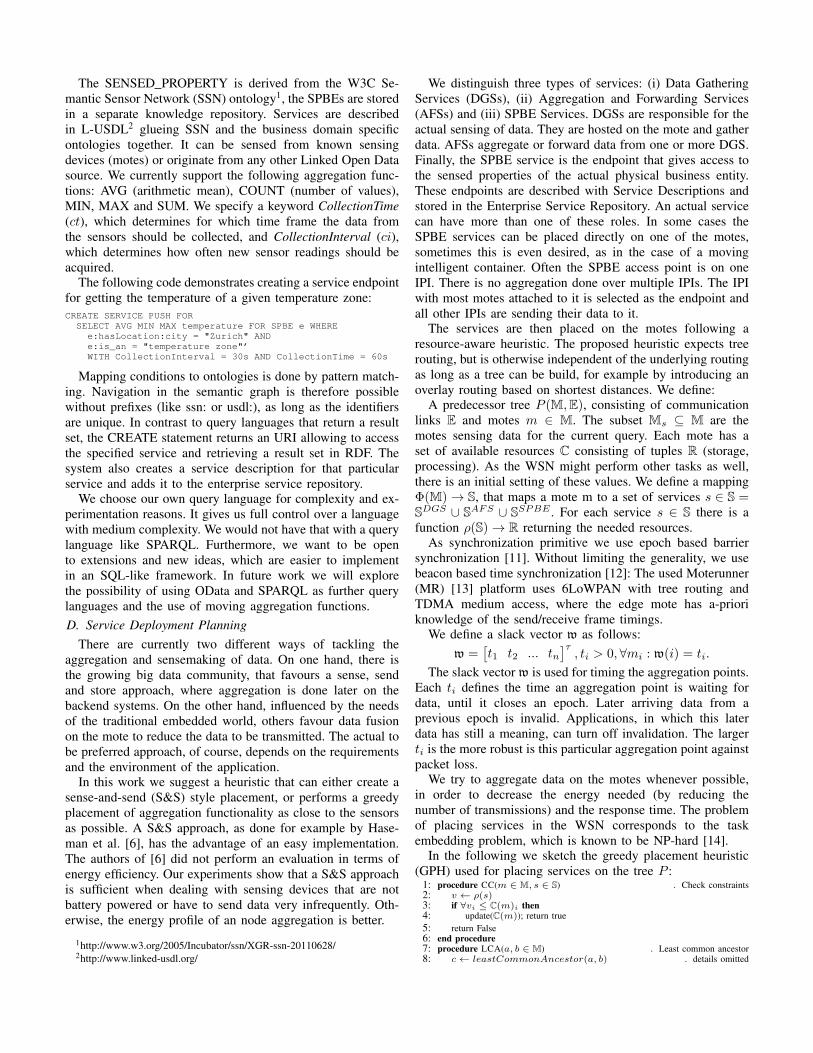
In the following we sketch the greedy placement heuristic(GPH) used for placing services on the tree P :
1: procedure CC(m ∈ M, s ∈ S) . Check constraints2: v ← ρ(s)3: if ∀vi ≤ C(m)i then4: update(C(m)); return true5: return False6: end procedure7: procedure LCA(a, b ∈ M) . Least common ancestor8: c← leastCommonAncestor(a, b) . details omitted

9: return c10: end procedure11: procedure GPH12: for all mi ∈ Ms do . Set DGS13: s← cs(mi) . Create service14: Φ(mi) := s15: SDGS ← SDGS ∪ {s}16: cc(mi, s)17: Ml ← sort(Ms) by level desc18: for all mi ∈ Ml do . Set AFS19: for j = 1..(|Ml| − i) do20: m← LCA(mi,mi+j)21: s← cs(m) . Create service22: if !cc(m,s) then . Find slot23: f ← false24: while ((!f) & m!=EdgeMote) do25: p← m.parent26: f ← cc(p, s)27: m← p
28: if (!f) then . No slot found29: m← IPI30: AggregationOnIPI(mi,mi+j )31: Φ(m) := s32: SAFS ← SAFS ∪ {s}33: end procedure
In a nutshell, the algorithm first places all DGSs to therespective motes, then sorts the motes by level and places theAFS using the least common ancestor (LCA) algorithm [15]to the closest ancestor in adherence of the constraints. Thiscan also be the IPI.
While setting the slack vector is application specific and cantake link and application specific characteristics into account,one possibility is to set it by the calculated time to collect datafrom the corresponding lower level services (DGS or AFS),multiplied by a factor βi to compensate packet loss. The slackvectors typically increase in each level of the tree from leaveto root, as the next level of AGS needs to wait for the resultsof their feeding AGS. In case of synchronous TDMA-basedmedium access control we can easily calculate the values foreach AFS slack vector value ti, with corresponding DGS withslack values tn...tm (without limiting the generality), Collec-tionTime ct and maximum transmission time ttmax(mi,mj)from mote mi to mote mj . This leads to the following valuesfor the DGS and AFS service slack values:
tn = ct ∗ β1, βi ≥ 1
ti = max(tn, .., tm)+
(max(ttmax(mn,mi)..ttmax(mm,mi)) ∗ βi), βi ≥ 1
Motes can join or leave the WSN at any time. When a newmote joins, the system integrates it by deploying a DGS ifnecessary, and determines the next possible AFS by applyingthe LCA algorithm. In cases, in which motes, that still havechildren (according the the current routing) leave the network,the MR platform will try to create a new tree. From an IPIpoint of view, motes reattaching to the tree are like new motes.They will look for an existing AFS and feed their data toit. If an SPBE endpoint leaves the network the system willcreate a new one on the IPI and change the service repositoryaccordingly. If a mote that has no direct path to a SPBEendpoint joins, the endpoint is also moved to the IPI and allcomponents accessing the service will get a service redirectionresponse.E. Service Creation and Deployment
Once the deployment plan has been calculated, the plat-form creates the corresponding services. We create on-mote
services in Java, compile them (see Figure 3(b)) and deploythem according to the mapping Φ, as calculated by thegreedy placement heuristic. Currently we are using CoAPover 6LoWPAN for communication. Code generation is donewith a parameterized template system. The services themselvesare parameterized as well, so that the important parametersCollectionTime, the slack time and the corresponding AFScan be changed during run-time.
F. Service Access
An application can access the created service through theservice URI. Furthermore, the service can be queried throughthe service repository. Each service is accessible through aCoAP RESTful interface and over HTTP via a CoAP proxyon the IPI. Both endpoints are stored in the service repositoryfor consumption by service consumers. All calls are RESTful(GET) and return RDF triples. A DELETE to the servicewould remove the service, just as the delete service statementin SPBEQL. With a POST to special resources as /ct or /stthe collection time (ct) and the slack vector (st) be changed.
VI. PROTOYPE IMPLEMENTATION
We built a prototype implementation and performed quan-titative evaluations. All code is written in Java. The platformis based on Java7. On the motes we use IBM Researchs’ MRplatform [13], with an improved version of their 6LoWPANprotocol. It uses a custom byte code and it has been shownthat the platform has a very good tradeoff between using aVM and energy consumption [16].
We created a custom CoAP-14 implementation. We usethe endpoint descriptions to generate code for specific RESTservices and add a small CoAP library with minimal overhead.CoAP uses a stop-and-wait congestion control algorithm,which needs only very limited resources for bookkeeping.
VII. EVALUATION
In this section we perform a quantitative analysis of ourSPBE-aware integration platform. In particular we evaluatedthe response times of services created by SPEQL as well asthe energy consumption of the complete system. Furthermore,we experimented with external RDF data sources and theirintegration into the platform.
A. Evaluation Scenario
We assume a retail scenario, in which all relevant infor-mation (store, goods, properties of stores and goods) are keptin semantic repositories. We connect these to form SPBEsand create services for them. In the stores different perishablegoods are stored in different temperature zones tzi. The wholestore is monitored by a WSN connected to one IPI. The WSNis monitoring this tzi and has information about the goods ineach particular temperature zones. The data sources used areas follows:
1) The tzi are stored an repository. It is linked to theparticular store, which has a specific location.
2) The goods in each tzi are also stored in an enterpriserepository as part of the retail system.
3) We have a dataset of locations, which allow to query forgeolocations, e. g. for all stores of the chain in Zurich.

Fig. 4: ScenarioTABLE I: Technical details of an IRIS Mote
CPU ATmega1281 (8Mhz) Serial Flash 512k Bytes Program Flash 128k bytes
RAM 8k bytes Current 8mA(act), 8µA(sleep) RF power 3 dBm (typ)
As shown in Figure 3(d) the business experts formulatesthe process in a business modeling language, which usesthe semantic repositories. Based on that the system createsbusiness rules (BRs). These BRs then trigger the generationof SPBEQL statements, which in turn generates software to bedeployed on the motes and on the IPIs. The generated servicesused by the business process are semantically described andstored in the semantic service repository. The modeler needsno knowledge about the WSN or any particular sensing device.
We created endpoints for a specific store in Zurich, withfour distinct temperature zones, with 12 sensing sensors ineach zone (see Figure 4). The endpoint delivers the maximum,minimum and the average temperature of all sensor readings.Based on this information the retail system does make deci-sions on the price of the specific goods (dynamic pricing). Weused ci = 5s and ct = 20s and averaged the results over 100runs for each experiment.B. Evaluation Setup
We conducted our experiments in a close to real-world setupin a living lab and with simulation support. The evaluationswere done using IRIS Motes with technical details as in TableI. We used the MR platform [13] with its simulation andprofiling tools. The MR platform uses a 6LoWPAN TDMAMAC protocol that builds up a multi-hop tree. The wholenetwork can be known, as the parent nodes send controlmessages to the edge mote as soon as they discover and adda new child or loose connectivity to one of their children.C. Experiments
Table II shows the measured times needed to setup thesystem. The duration from issuing a SPBEQL statement to acomplete system (without programming 3, but with compiling)is around 28s. The total time needed to set up the systemdepends mainly on the programming of the motes, as there isno multicast mechanism each mode has to be programmedindividually (multicast). This is a limition of the currentsystem. Unicast/Broadcast programming techniques, like theSNOMC protocol [17], exist. A multicast mechanism would
3Programming in this case means transfering the bytecode to the mote andstoring it on flash memory
speedup the overall system setup time. Configuration of theservices on the motes can then be done via the REST interface.
In Table III we show the memory usage of the three servicetypes. The actual memory needed depends on the data to bestored on mote. Its upper bound can be easily calculated perepoch and is used in the GPH.
After the initial set up, we measured the response timesfor a service endpoint on the gateway mote, and comparedthat to a service endpoint on the IPI. As shown in Figure 9,in pull mode the system needs around 20s for data gatheringplus an overhead for communication. In push mode the datais immeadiately available after an initial data gathering round.
0,03 0,06 0,13 0,25 0,50 1,00 2,00 4,00 8,00
16,00
1 3 5 7 9 11 13 15 17 19 21 23 25 27 29 31 33 35 37 39 41 43 45 47 49 51 53 55 57 59
resp
on
se t
ime
[s]
request issue time [s]
push (on mote) pull (on mote) push (on IPI)
min: 207/20139/42 max: 1237/22429/21189 median: 319/21418/60 mean: 4108/21392/3924 (in ms, for push/pull/push IPI)
25,00
min: 207/20247/42 max: 420/22429/192 median: 255/21831/56 mean: 278/21488/58 (starting from second 22)
Fig. 9: Response times for request issued at request time t (log2 scale)
The response times for a running system are shown inFigure 7 for a service endpoint on a mote, on a mote at level2 in a tree, as well as on the IPI via CoAP and HTTP. Weaccessed the CoAP and HTTP interfaces with a machine onthe same local subnet, which handled other traffic as well. Thedata we got from the WSN was relatively stable, while for thecommunication over Ethernet we observed some peaks.
The energy profile of our prototype is shown in Figure 6.We measured (by simulation) the system in pull mode, in pushmode, and a S&S counterpart with all motes sending data tothe IPI. The aggregation approach showed to be more energyefficient, as the computation time for the aggregation neededless energy than the additional transmission and receive cyclesneeded in the S&S approach. Pull is more energy efficient, forsmall request rates, for the price of longer response times.
As explained in section V-C the system allows to includeexternal RDF data as sensor readings. We set up a second IPIwith a single mote attached to it. Instead of adding the secondIPI to the platform directly we publish the sensor readings asRDF data to a local server and to a server on the Internet.We added both servers as external RDF sensor sources to oursystem and measured the service response times (Figure 5)for the whole system and the external sources. In push andpull mode with an endpoint on the IPI, the influence of thetwo external sources on the system is negligable, both forlocal and remote data sources as long as ct is large enoughto compensate the latency. As soon as the WSN respondsfaster than the external sensor source the picture changes.In cases were the freshness of data is most important thelatency of the Internet connection becomes cruical and thelatency (CollectionTime) of the whole system would have tobe increased to get accurate data.
Finally, we tested how the system reacts towards change ofthe underlying sensing infrastructure: We removed one AFS

0,02
0,03
0,06
0,13
0,25
0,50
1,00
2,00
4,00
8,00
16,00
1 3 5 7 9 11 13 15 17 19 21 23 25 27 29 31 33 35 37 39 41 43 45 47 49 51 53 55 57 59
Re
spo
nse
tim
e [
s]
request issue time [s]
push (on mote) pull (on mote) push (on IPI) Mote (local) Mote (inet)
Fig. 5: Service Response times for external sensor sources
Sink AFS / FW DGS
Push 9241 9585 14422
S&S 9539 9706 14429
Pull 1R 8753 8929 9354
Pull 8R 9480 9695 12927
8500
9500
10500
11500
12500
13500
14500
Ene
rgy
[mA
s], 1
0m
in
+1.2
47
%
+0,0
4%
+3.1
24
%
Fig. 6: Energy consumption (in mAs, 10min)
t σ
Generate mote services 2520 350
Compile mote services 8410 2123
Compile IPI service 4120 210
Program mote 39200 5213
Query Service Repository 123 51
Query SPSE 661 94
Query geolocations 472 53
SPBEQL to System 28320 4476
TABLE II: Average systemsetup time t and std. deviationσ in ms
L1.CoAP L2.CoAP IPI.CoAP IPI.HTTP
200
400
600
800
1000
1200
Fig. 7: Service Response Time (in ms)
Flash Stack Heap
DGS 923 256 2348
AFS 800 234 2205
SPBE 810 245 2218
TABLE III: Memory con-sumption (in byte)
0
10
20
30
40
50
60
70
Reprogramming Switching Reallocation IPI
tim
e [
in s
]
Service Repository
Code generation and deployment
RESTful reprogramming
Reprogramming
Fig. 8: Service reallocation time (in s)
below the edge mote. The system then recreates a tree. Thenew AFS node, which has only a DGS service on it, nowneeds to be reprogrammed. This takes almost 40s, as shownin Figure 8. If the AGS is already installed on the moteaggregation infrastructure, changes can be performed moreeasily: In such cases only a few REST calls have to be issuedby the Command and Control (C&C) module. Wheneverpossible programming of motes is to be avoided. Here thesystem is available after around 10s (σ = 3.3s). In a secondexperiment, we forced a service reallocation from the edgemote to the IPI. The C&C issues a command to the currentendpoint to respond with service temporarily unavailable. Atthe same time it will compile and deploy a new endpoint tothe IPI and updates the service repository. The former endpointfrom now on will respond with a service redirected code.
VIII. SUMMARY
We presented Semantic Physical Business Entities as anabstraction for gathering data about business entities. It de-couples the entities from the actual sensing devices andenables writing applications without any knowledge about theunderlying hardware. Interoperability and machine-readabilityis achieved through ontologies and common vocabularies. Datais gathered and aggregated by an integration platform using aquery language. The platform compiles the services dependingon the query. These services are described by semantic servicedescriptions and are fully controllable through a RESTfulinterface. Feasibility experiments demonstrated that SPBEscan be integrated into enterprise systems with reasonableenergy consumption, set up and response times.
ACKNOWLEDGMENT
The research on this topic received funding from the Eu-ropean Commission under grant 257521 (IOT-A) and grant285248 (FI-WARE). We would like to thank the MoterunnerTeam at IBM Research, especially Marcus Oestreicher, as wellas our students Theano Mintsi and Michael Gede for theirvaluable support.
REFERENCES
[1] Z. Shelby and C. Bormann, 6LoWPAN: the wireless embedded internet.Wiley, 2011, vol. 43.
[2] Z. Shelby, K. Hartke, C. Bormann, and B. Frank, “Constrained Appli-cation Protocol (CoAP), Internet-Draft,” 2011.
[3] T. Berners-Lee, “Linked Data - Design Issues,” 2006.[4] K. Sperner, S. Meyer, and C. Magerkurth, “Introducing entity-based
concepts to business process modeling,” in BPMN. Springer, 2011.[5] M. Thoma, S. Meyer, K. Sperner, S. Meissner, and T. Braun, “On IoT-
services: Survey, Classification and Enterprise Integration,” 2012 IEEEInternational Conference on the Internet of Things, vol. 0, 2012.
[6] H. Hasemann, O. Kleine, A. Kroller, M. Leggieri, and D. Pfisterer,“Annotating real-world objects using semantic entities,” in WirelessSensor Networks. Springer, 2013, pp. 67–82.
[7] M. Iqbal, H. B. Lim, W. Wang, and Y. Yao, “A service oriented modelfor semantics-based data management in wireless sensor networks,” inAdvanced Information Networking and Applications. IEEE, 2009.
[8] S. R. Madden, M. J. Franklin, J. M. Hellerstein, and W. Hong, “Tinydb:An acquisitional query processing system for sensor networks,” ACMTransactions on Database Systems (TODS), vol. 30, no. 1, 2005.
[9] J. Cardoso, C. Pedrinaci, T. Leidig, P. Rupino, and P. De Leenheer,“Open semantic service networks,” 2012.
[10] A. Zahariev, “Google app engine,” Helsinki University of Technology,2009.
[11] S. Shang and K. Hwang, “Distributed hardwired barrier synchronizationfor scalable multiprocessor clusters,” Parallel and Distributed Systems,IEEE Transactions on, vol. 6, no. 6, 1995.
[12] H. Dai and R. Han, “Tsync: a lightweight bidirectional time synchroniza-tion service for wireless sensor networks,” ACM SIGMOBILE MobileComputing and Communications Review, vol. 8, no. 1, 2004.
[13] A. Caracas, T. Kramp, M. Baentsch, M. Oestreicher, T. Eirich, andI. Romanov, “Mote runner: A multi-language virtual machine for smallembedded devices,” in SENSORCOMM’09. IEEE, 2009.
[14] Z. Abrams and J. Liu, “Greedy is good: On service tree placement forin-network stream processing,” in ICDCS 2006. IEEE, 2006.
[15] M. A. Bender and M. Farach-Colton, “The lca problem revisited,” inLATIN 2000: Theoretical Informatics. Springer, 2000, pp. 88–94.
[16] A. Caracas, C. Lombriser, Y. Pignolet, T. Kramp, T. Eirich, R. Adels-berger, and U. Hunkeler, “Energy-efficiency through micro-managingcommunication and optimizing sleep,” in 8th International Conferenceon Sensor, Mesh and Ad Hoc Comm. and Networks. IEEE, 2011.
[17] G. Wagenknecht, M. Anwander, and T. Braun, “Snomc: an overlaymulticast protocol for wireless sensor networks,” in Wireless On-demandNetwork Systems and Services (WONS), 2012 9th Annual Conference on.IEEE, 2012, pp. 75–78.