Embed Size (px)
Citation preview
Integrity, Management and Repair
Thursday 2nd February 2017
Real Time Electrical Integrity Testing
Calvin Youngman Technical Manager Imes International Limited

The requirement to test submarine cables and connections has long being recognised in the Offshore Oil and Gas industry. As early as the 1990s a need was further identified for quicker, safer and more effective means of electrical testing on subsea submarine cables than the usual fault finding from shore, platform or vessel. These traditional methods involved a substantial undertaking in time and money for support vessels, manpower, and production downtime and often the already suspect electrical architecture was put at further risk by the process of cable end recovery and the testing itself. 1997, and Imes began working with BP and Aker solutions to develop a system for electrical testing at point, subsea. Initial systems were simple subsea pods, ROV carried and deployed, that measured and logged data for later recovery and analysis mainly for fault finding. Subsea Electrical Testing and its uses has come along way since then....
History of Submarine Electrical Testing
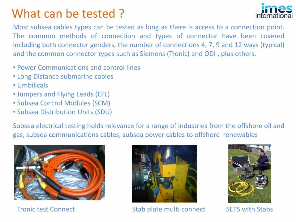
Most subsea cables types can be tested as long as there is access to a connection point. The common methods of connection and types of connector have been covered including both connector genders, the number of connections 4, 7, 9 and 12 ways (typical) and the common connector types such as Siemens (Tronic) and ODI , plus others.
• Power Communications and control lines • Long Distance submarine cables • Umbilicals • Jumpers and Flying Leads (EFL) • Subsea Control Modules (SCM) • Subsea Distribution Units (SDU)
Subsea electrical testing holds relevance for a range of industries from the offshore oil and gas, subsea communications cables, subsea power cables to offshore renewables
What can be tested ?
Tronic test Connect Stab plate multi connect SETS with Stabs
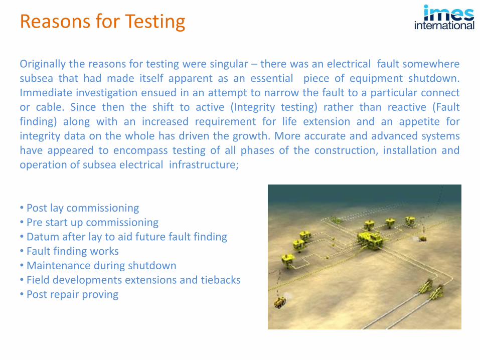
Originally the reasons for testing were singular – there was an electrical fault somewhere subsea that had made itself apparent as an essential piece of equipment shutdown. Immediate investigation ensued in an attempt to narrow the fault to a particular connect or cable. Since then the shift to active (Integrity testing) rather than reactive (Fault finding) along with an increased requirement for life extension and an appetite for integrity data on the whole has driven the growth. More accurate and advanced systems have appeared to encompass testing of all phases of the construction, installation and operation of subsea electrical infrastructure; • Post lay commissioning • Pre start up commissioning • Datum after lay to aid future fault finding • Fault finding works • Maintenance during shutdown • Field developments extensions and tiebacks • Post repair proving
Reasons for Testing
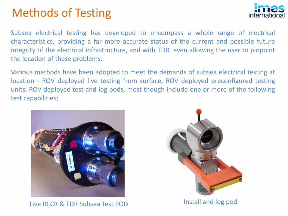
Subsea electrical testing has developed to encompass a whole range of electrical characteristics, providing a far more accurate status of the current and possible future integrity of the electrical infrastructure, and with TDR even allowing the user to pinpoint the location of these problems.
Various methods have been adopted to meet the demands of subsea electrical testing at location - ROV deployed live testing from surface, ROV deployed preconfigured testing units, ROV deployed test and log pods, most though include one or more of the following test capabilities;
Methods of Testing
Live IR,CR & TDR Subsea Test POD Install and log pod
Insulation resistance (IR) involves testing the strength of the insulation between individual cable cores and each core to seawater. Insulation damage either during install, damage in service or longer term insulation breakdown and failure are the most common causes of issues with cables - especially so for submarine cables where the surrounding medium is liquid under pressure and conductive .
There are various sub sets of IR testing that companies can perform to further analyse the status of the insulation over and above a single spot test pass or fail
Type of Testing
• PI Test (Polarisation Index) • DAR Test (Dielectric Absorption Test)
PI testing and DAR testing help assess the deterioration of insulation and involves repeat IR tests following complete energization of the line. DAR for example is calculated as a simple ratio between the IR figures taken at 30 second and 60 second intervals following complete polarisation.
The DAR Ratio is calculated as IR60/ IR30
The higher the DAR ratio the better <1.25 considered suspect >1.6 being good
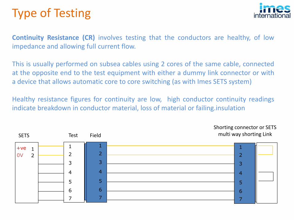
Continuity Resistance (CR) involves testing that the conductors are healthy, of low impedance and allowing full current flow. This is usually performed on subsea cables using 2 cores of the same cable, connected at the opposite end to the test equipment with either a dummy link connector or with a device that allows automatic core to core switching (as with Imes SETS system) Healthy resistance figures for continuity are low, high conductor continuity readings indicate breakdown in conductor material, loss of material or failing.insulation
Type of Testing
1
2
3
4
5
6
7
1
2
3
4
5
6
7
1
2
3
4
5
6
7
+ve
2
1
0V
SETS Field
Shorting connector or SETS multi way shorting Link Test
But what do these tests really tell you ? Okay you may find an issue with low IR or poor core conductivity but where in the line is this fault. In short cable lengths it may be simpler just to “change out than find out” – but what about long runs, trenched cables and umbilicals covering many Kilometres ?
In these circumstances knowing the location to effect a repair (if possible) is essential;
Time Domain Reflectometry (TDR) This is where TDR really comes into its own. TDR basically sends a fast rising short duration electrical ‘ping’ down cable and monitors the time delay, the amplitude and sign (Pos or Neg) of the reflected return signal. This allows the operator via the software to determine the type and location of a problem. The standard characteristics of the cable are required to accurately determine the propagation speed, and hence the distance, and the attenuation hence the actual loss (or gain) in impedance at the location.
However the limitation of TDR should be understood - The distance accuracy is a percentage of measurement range so as the cable length increases so does the uncertainty of fault location distance.
Type of Testing
PB-L1 & PB-L2 to E IR
0
0.5
1
1.5
2
2.5
17:29:04 17:29:26 17:29:47 17:30:06 17:30:27 17:30:47 17:31:10 17:31:29
Time (hh:mm:ss)
Resis
tan
ce (
M o
hm
s)
PB-L1 & PB-L2 to E IR
PA-L1 to Earth
0.00000
0.20000
0.40000
0.60000
0.80000
1.00000
1.20000
1.40000
1.60000
1.80000
2.00000
10:23:37 10:24:29 10:25:20 10:26:12 10:27:04 10:27:56 10:28:48
Time (hh:mm:ss)
IR (
G o
hm
s)
PA-L1 to Earth
1.86 G ohms
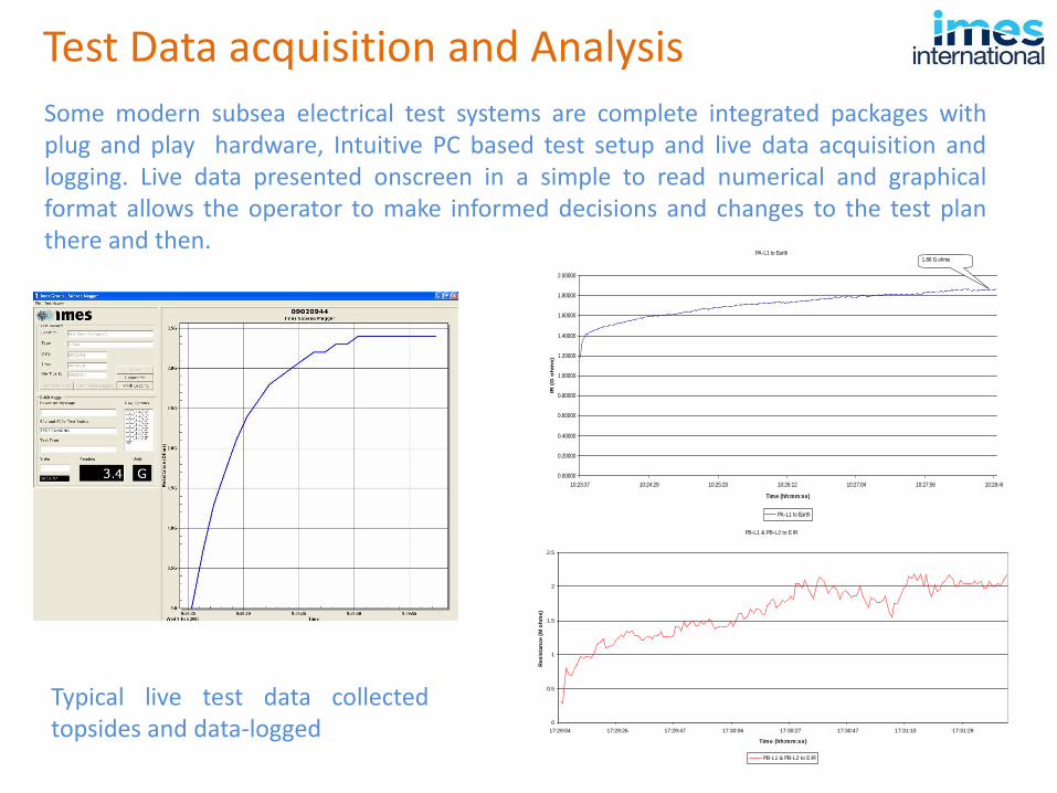
Typical live test data collected topsides and data-logged
Test Data acquisition and Analysis
Some modern subsea electrical test systems are complete integrated packages with plug and play hardware, Intuitive PC based test setup and live data acquisition and logging. Live data presented onscreen in a simple to read numerical and graphical format allows the operator to make informed decisions and changes to the test plan there and then.
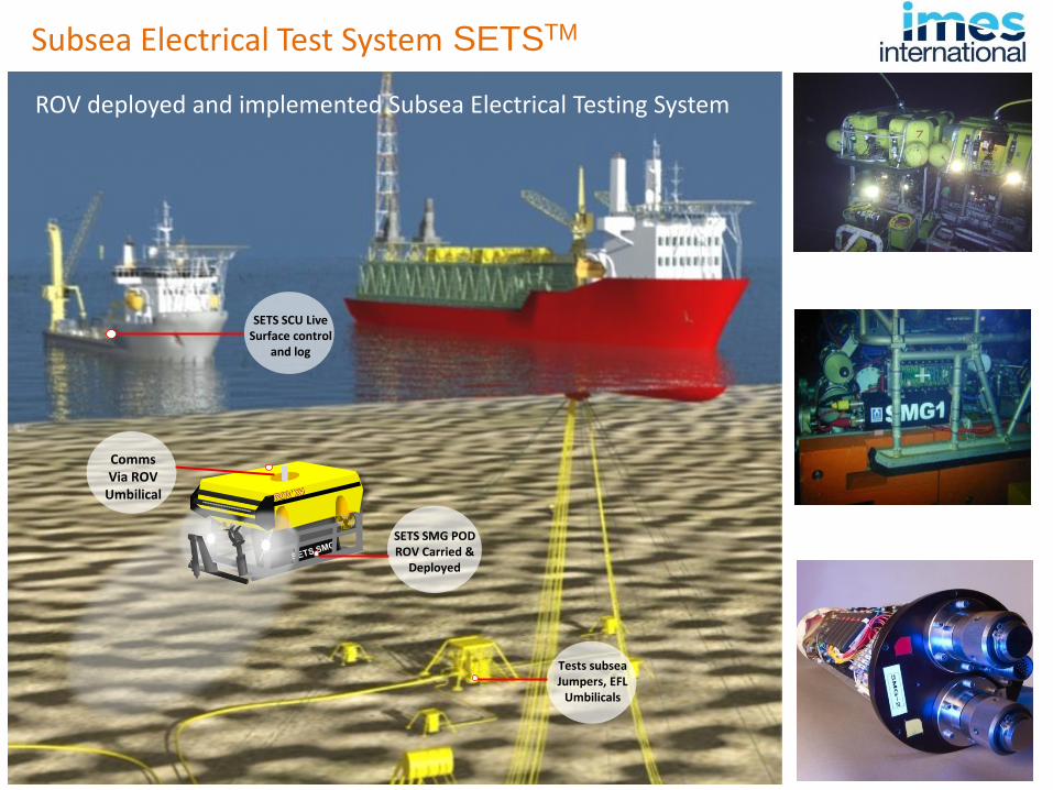
Subsea Electrical Test System SETSTM
Real Time Electrical Integrity Testing
Subsea Electrical Test System SETSTM
Comms Via ROV
Umbilical
Tests subsea Jumpers, EFL
Umbilicals
SETS SMG POD ROV Carried &
Deployed
SETS SCU Live Surface control
and log
ROV deployed and implemented Subsea Electrical Testing System
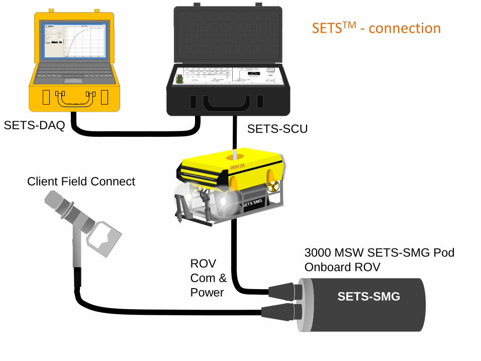
SETS-SCU SETS-DAQ
SETS-SMG
3000 MSW SETS-SMG Pod
Onboard ROV ROV
Com &
Power
Client Field Connect
SETSTM - connection

• ROV Carried SETS SMG test Pod • Live Data via ROV Umbilical to surface • Surface controlled testing via surface control unit (SETS SCU) • Live data visualisation, graph, alarms and data logging (SETS DAQ)
Subsea Electrical Test System SETSTM
SETS-SCU
Bi Directional Com X 2
SETS-DAQ
SETS-SMG
ROV
SURFACE SUBSEA
110/240VAC 50/60Hz
Bi Directional Com X 2
& 110VAC
Test Cable
Data
Field Connector
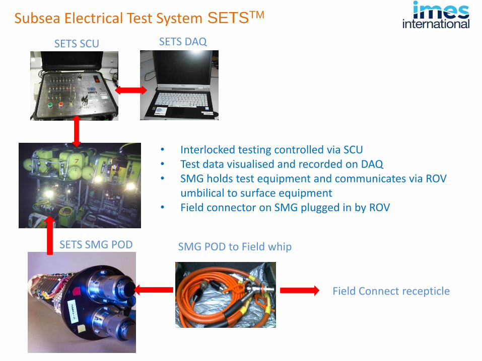
Subsea Electrical Test System SETSTM
SETS DAQ SETS SCU
SETS SMG POD
Field Connect recepticle
• Interlocked testing controlled via SCU • Test data visualised and recorded on DAQ • SMG holds test equipment and communicates via ROV
umbilical to surface equipment • Field connector on SMG plugged in by ROV
SMG POD to Field whip

• Safer, faster more accurate testing
• Live subsea electrical integrity testing
• IR, CR and TDR measurements
• Fault finding, commissioning, field extension
• Live display and data logging functionality
• Rapid mobilisation and reduced testing time
SETS customers : BP, Shell, Petrobras, Aker Solutions, SS7, DOF Subsea, Noble Energy
Subsea Electrical Test System SETSTM
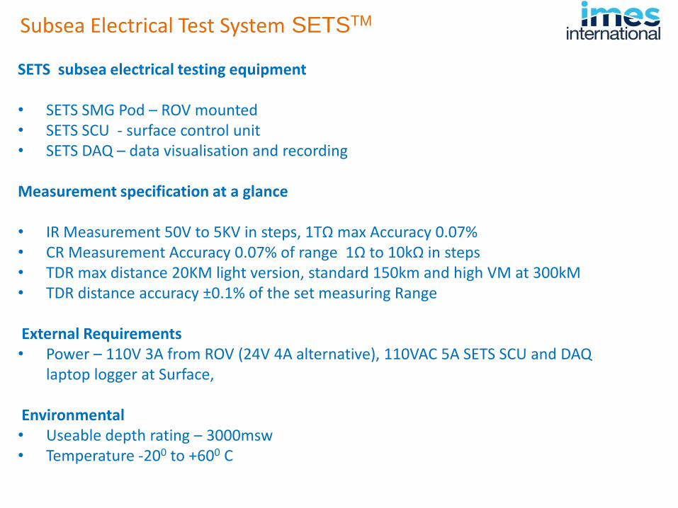
SETS subsea electrical testing equipment • SETS SMG Pod – ROV mounted • SETS SCU - surface control unit • SETS DAQ – data visualisation and recording Measurement specification at a glance • IR Measurement 50V to 5KV in steps, 1TΩ max Accuracy 0.07% • CR Measurement Accuracy 0.07% of range 1Ω to 10kΩ in steps • TDR max distance 20KM light version, standard 150km and high VM at 300kM • TDR distance accuracy ±0.1% of the set measuring Range
External Requirements • Power – 110V 3A from ROV (24V 4A alternative), 110VAC 5A SETS SCU and DAQ
laptop logger at Surface,
Environmental • Useable depth rating – 3000msw • Temperature -200 to +600 C
Subsea Electrical Test System SETSTM
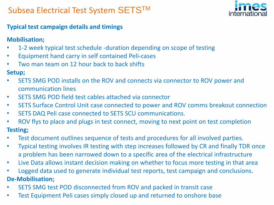
Typical test campaign details and timings
Mobilisation; • 1-2 week typical test schedule -duration depending on scope of testing • Equipment hand carry in self contained Peli-cases • Two man team on 12 hour back to back shifts Setup; • SETS SMG POD installs on the ROV and connects via connector to ROV power and
communication lines • SETS SMG POD field test cables attached via connector • SETS Surface Control Unit case connected to power and ROV comms breakout connection • SETS DAQ Peli case connected to SETS SCU communications. • ROV flys to place and plugs in test connect, moving to next point on test completion Testing; • Test document outlines sequence of tests and procedures for all involved parties. • Typical testing involves IR testing with step increases followed by CR and finally TDR once
a problem has been narrowed down to a specific area of the electrical infrastructure • Live Data allows instant decision making on whether to focus more testing in that area • Logged data used to generate individual test reports, test campaign and conclusions. De-Mobilisation; • SETS SMG test POD disconnected from ROV and packed in transit case • Test Equipment Peli cases simply closed up and returned to onshore base
Subsea Electrical Test System SETSTM
www.imesint.co.uk
Principles of IMES Submarine Cable Repair System Once a fault has been determined and located in a cable the principle is to reinstate electrical continuity and Insulation resistance via mechanical means. Imes working with its Seanamic group partners - Umbilicals International. Caley and pipelay systems has ongoing proof of concept testing generally based around the following( simplified works •Clearing the area to expose the cable (for example with mass flow excavators ) •Application and clamping of the repair shell •Extraction of water and contaminants •Gaseous purge •Partial erosion cutback and clean •Re-introduction of dielectric water block fillers and anti wicking gels • Final reinstatement of self healing hi dielectric strength liquid insulation. • Repair clamp removal •Final testing •Cable retrenched (as required)
Future of Submarine Electrical Integrity
Thank you for attending
www.imes-int.co.uk
www.imesint.co.uk
Subsea Electrical Test System SETSTM
Riser Inhaul Camera Systems RICSTM
Mooring Tension Systems