Embed Size (px)
Citation preview
Intel® Galileo Board Data Painting
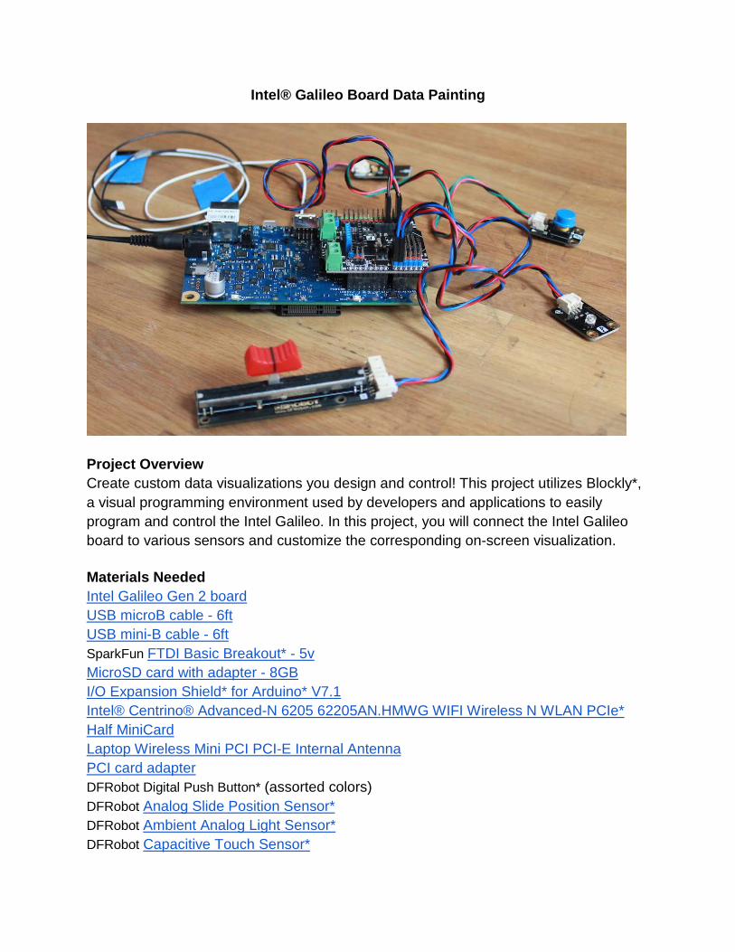
Project Overview Create custom data visualizations you design and control! This project utilizes Blockly*, a visual programming environment used by developers and applications to easily program and control the Intel Galileo. In this project, you will connect the Intel Galileo board to various sensors and customize the corresponding on-screen visualization. Materials Needed Intel Galileo Gen 2 board USB microB cable - 6ft USB mini-B cable - 6ft SparkFun FTDI Basic Breakout* - 5v MicroSD card with adapter - 8GB I/O Expansion Shield* for Arduino* V7.1 Intel® Centrino® Advanced-N 6205 62205AN.HMWG WIFI Wireless N WLAN PCIe* Half MiniCard Laptop Wireless Mini PCI PCI-E Internal Antenna PCI card adapter DFRobot Digital Push Button* (assorted colors) DFRobot Analog Slide Position Sensor* DFRobot Ambient Analog Light Sensor* DFRobot Capacitive Touch Sensor*
Additional Tools Computer or laptop Painter’s tape or other lightly adhesive tape (Optional) small board of piece of cardboard Approximate Cost $175 per kit Time Required 6+ hours Grade Range 9th -12th
Skill Prerequisites ● Previous experience working
with microcontrollers/electronics
Learning Objectives ● Encourage active discovery of
Intel Galileo capabilities ● Encourage active discovery
through hands-on exploration of common electronic components
● Explore programming the Intel Galileo through visual programming interface
● Create multifaceted data visualizations from multiple sources
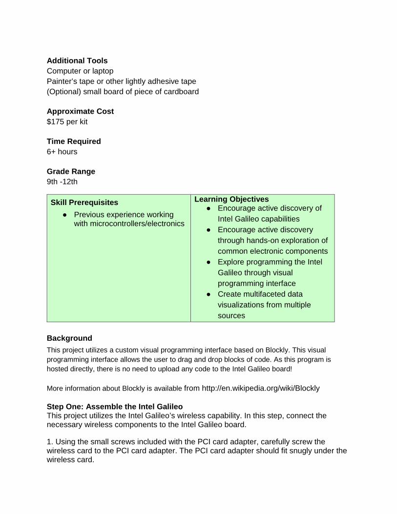
Background This project utilizes a custom visual programming interface based on Blockly. This visual programming interface allows the user to drag and drop blocks of code. As this program is hosted directly, there is no need to upload any code to the Intel Galileo board! More information about Blockly is available from http://en.wikipedia.org/wiki/Blockly Step One: Assemble the Intel Galileo This project utilizes the Intel Galileo’s wireless capability. In this step, connect the necessary wireless components to the Intel Galileo board. 1. Using the small screws included with the PCI card adapter, carefully screw the wireless card to the PCI card adapter. The PCI card adapter should fit snugly under the wireless card.
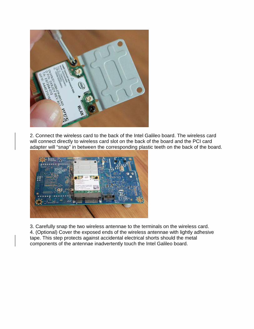
2. Connect the wireless card to the back of the Intel Galileo board. The wireless card will connect directly to wireless card slot on the back of the board and the PCI card adapter will “snap” in between the corresponding plastic teeth on the back of the board.
3. Carefully snap the two wireless antennae to the terminals on the wireless card. 4. (Optional) Cover the exposed ends of the wireless antennae with lightly adhesive tape. This step protects against accidental electrical shorts should the metal components of the antennae inadvertently touch the Intel Galileo board.
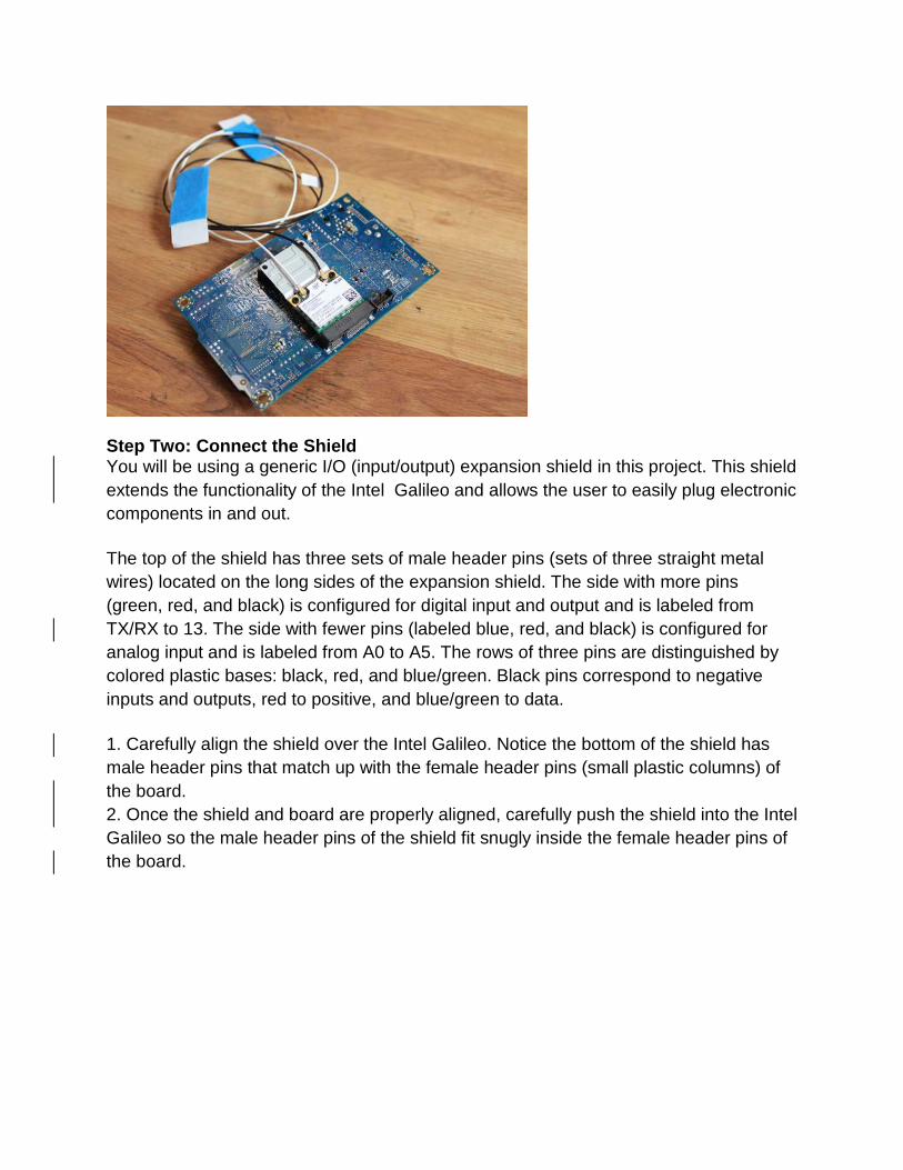
Step Two: Connect the Shield You will be using a generic I/O (input/output) expansion shield in this project. This shield extends the functionality of the Intel Galileo and allows the user to easily plug electronic components in and out. The top of the shield has three sets of male header pins (sets of three straight metal wires) located on the long sides of the expansion shield. The side with more pins (green, red, and black) is configured for digital input and output and is labeled from TX/RX to 13. The side with fewer pins (labeled blue, red, and black) is configured for analog input and is labeled from A0 to A5. The rows of three pins are distinguished by colored plastic bases: black, red, and blue/green. Black pins correspond to negative inputs and outputs, red to positive, and blue/green to data. 1. Carefully align the shield over the Intel Galileo. Notice the bottom of the shield has male header pins that match up with the female header pins (small plastic columns) of the board. 2. Once the shield and board are properly aligned, carefully push the shield into the Intel Galileo so the male header pins of the shield fit snugly inside the female header pins of the board.
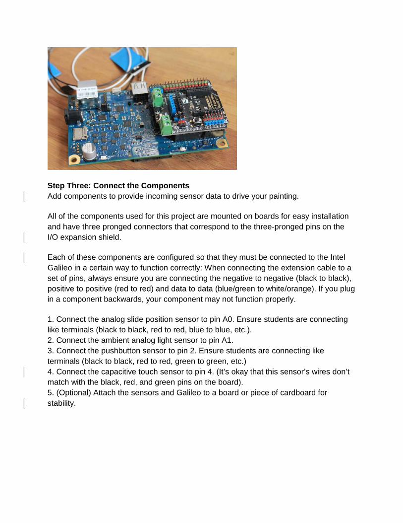
Step Three: Connect the Components Add components to provide incoming sensor data to drive your painting. All of the components used for this project are mounted on boards for easy installation and have three pronged connectors that correspond to the three-pronged pins on the I/O expansion shield. Each of these components are configured so that they must be connected to the Intel Galileo in a certain way to function correctly: When connecting the extension cable to a set of pins, always ensure you are connecting the negative to negative (black to black), positive to positive (red to red) and data to data (blue/green to white/orange). If you plug in a component backwards, your component may not function properly. 1. Connect the analog slide position sensor to pin A0. Ensure students are connecting like terminals (black to black, red to red, blue to blue, etc.). 2. Connect the ambient analog light sensor to pin A1. 3. Connect the pushbutton sensor to pin 2. Ensure students are connecting like terminals (black to black, red to red, green to green, etc.) 4. Connect the capacitive touch sensor to pin 4. (It’s okay that this sensor’s wires don’t match with the black, red, and green pins on the board). 5. (Optional) Attach the sensors and Galileo to a board or piece of cardboard for stability.

A pinout for the connecting the sensors is provided below.
Step Four: Install the Software Download the necessary software for the Intel Galileo. 1. Insert the SD card/adapter into your computer. 2. Download the program files from http://intel.ly/1zy4pPH. 3. Unzip the contents of the file. 4. Copy the contents of the file to the SD card. If using Mac* OS X, the file contents should look like the image below.
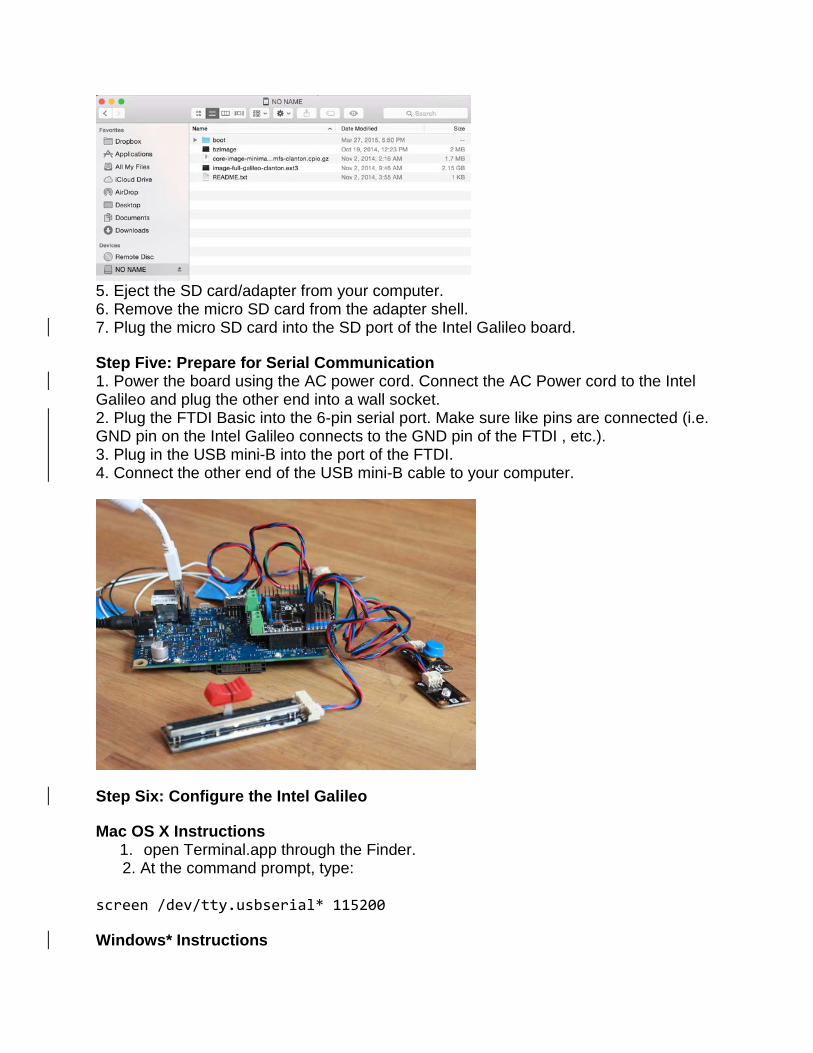
5. Eject the SD card/adapter from your computer. 6. Remove the micro SD card from the adapter shell. 7. Plug the micro SD card into the SD port of the Intel Galileo board. Step Five: Prepare for Serial Communication 1. Power the board using the AC power cord. Connect the AC Power cord to the Intel Galileo and plug the other end into a wall socket. 2. Plug the FTDI Basic into the 6-pin serial port. Make sure like pins are connected (i.e. GND pin on the Intel Galileo connects to the GND pin of the FTDI , etc.). 3. Plug in the USB mini-B into the port of the FTDI. 4. Connect the other end of the USB mini-B cable to your computer.
Step Six: Configure the Intel Galileo Mac OS X Instructions
1. open Terminal.app through the Finder. 2. At the command prompt, type: screen /dev/tty.usbserial* 115200 Windows* Instructions
1. Download PuTTY from http://bit.ly/1jsQjnt 2. Run PuTTY. 3. Select the “Serial” radio button on the right of the screen. 4. In the Serial Line box, enter the COM port of your Intel Galileo. 5. In the Speed box, enter 115200. 6. Press Open at the bottom.
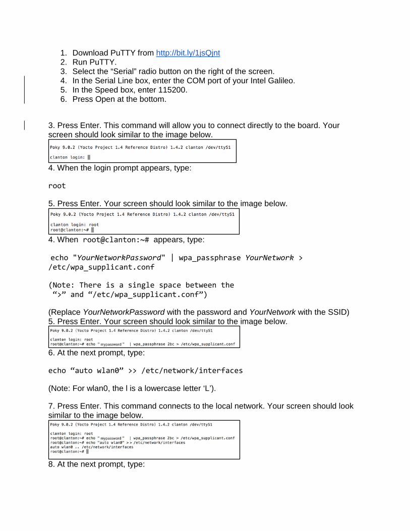
3. Press Enter. This command will allow you to connect directly to the board. Your screen should look similar to the image below.
4. When the login prompt appears, type: root 5. Press Enter. Your screen should look similar to the image below.
4. When root@clanton:~# appears, type: echo "YourNetworkPassword" | wpa_passphrase YourNetwork > /etc/wpa_supplicant.conf (Note: There is a single space between the “>” and “/etc/wpa_supplicant.conf”) (Replace YourNetworkPassword with the password and YourNetwork with the SSID) 5. Press Enter. Your screen should look similar to the image below.
6. At the next prompt, type: echo “auto wlan0” >> /etc/network/interfaces (Note: For wlan0, the l is a lowercase letter ‘L’). 7. Press Enter. This command connects to the local network. Your screen should look similar to the image below.
8. At the next prompt, type:
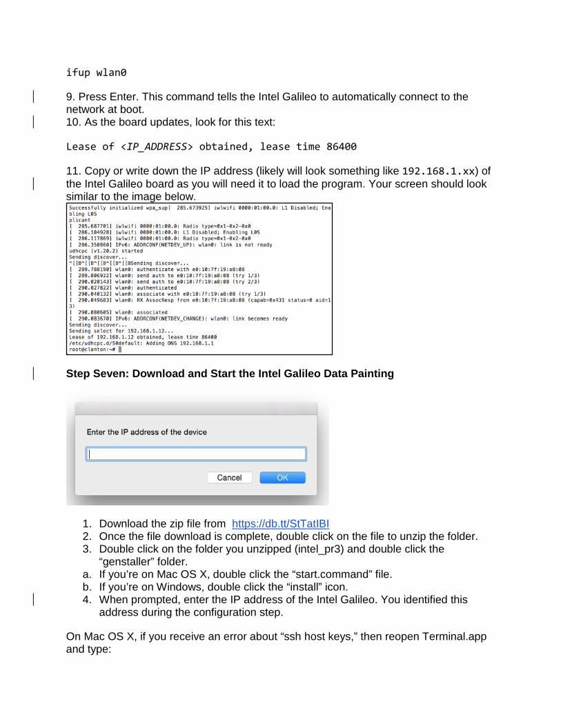
ifup wlan0 9. Press Enter. This command tells the Intel Galileo to automatically connect to the network at boot. 10. As the board updates, look for this text: Lease of <IP_ADDRESS> obtained, lease time 86400 11. Copy or write down the IP address (likely will look something like 192.168.1.xx) of the Intel Galileo board as you will need it to load the program. Your screen should look similar to the image below.
Step Seven: Download and Start the Intel Galileo Data Painting
1. Download the zip file from https://db.tt/StTatIBI 2. Once the file download is complete, double click on the file to unzip the folder. 3. Double click on the folder you unzipped (intel_pr3) and double click the
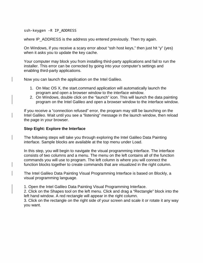
“genstaller” folder. a. If you’re on Mac OS X, double click the “start.command” file. b. If you’re on Windows, double click the “install” icon. 4. When prompted, enter the IP address of the Intel Galileo. You identified this
address during the configuration step. On Mac OS X, if you receive an error about “ssh host keys,” then reopen Terminal.app and type:
ssh-keygen -R IP_ADDRESS where IP_ADDRESS is the address you entered previously. Then try again. On Windows, if you receive a scary error about “ssh host keys,” then just hit “y” (yes) when it asks you to update the key cache. Your computer may block you from installing third-party applications and fail to run the installer. This error can be corrected by going into your computer’s settings and enabling third-party applications. Now you can launch the application on the Intel Galileo.
1. On Mac OS X, the start.command application will automatically launch the program and open a browser window to the interface window.
2. On Windows, double click on the “launch” icon. This will launch the data painting program on the Intel Galileo and open a browser window to the interface window.
If you receive a “connection refused” error, the program may still be launching on the Intel Galileo. Wait until you see a “listening” message in the launch window, then reload the page in your browser. Step Eight: Explore the Interface The following steps will take you through exploring the Intel Galileo Data Painting interface. Sample blocks are available at the top menu under Load. In this step, you will begin to navigate the visual programming interface. The interface consists of two columns and a menu. The menu on the left contains all of the function commands you will use to program. The left column is where you will connect the function blocks together to create commands that are visualized in the right column. The Intel Galileo Data Painting Visual Programming Interface is based on Blockly, a visual programming language. 1. Open the Intel Galileo Data Painting Visual Programming Interface. 2. Click on the Shapes tool on the left menu. Click and drag a “Rectangle” block into the left hand window. A red rectangle will appear in the right column. 3. Click on the rectangle on the right side of your screen and scale it or rotate it any way you want.
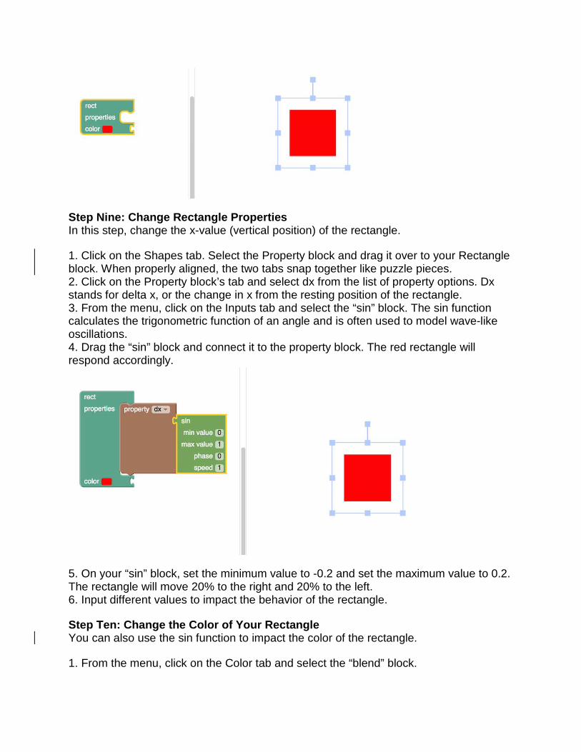
Step Nine: Change Rectangle Properties In this step, change the x-value (vertical position) of the rectangle. 1. Click on the Shapes tab. Select the Property block and drag it over to your Rectangle block. When properly aligned, the two tabs snap together like puzzle pieces. 2. Click on the Property block’s tab and select dx from the list of property options. Dx stands for delta x, or the change in x from the resting position of the rectangle. 3. From the menu, click on the Inputs tab and select the “sin” block. The sin function calculates the trigonometric function of an angle and is often used to model wave-like oscillations. 4. Drag the “sin” block and connect it to the property block. The red rectangle will respond accordingly.
5. On your “sin” block, set the minimum value to -0.2 and set the maximum value to 0.2. The rectangle will move 20% to the right and 20% to the left. 6. Input different values to impact the behavior of the rectangle. Step Ten: Change the Color of Your Rectangle You can also use the sin function to impact the color of the rectangle. 1. From the menu, click on the Color tab and select the “blend” block.

2. Attach the blend block to the corresponding color section on the rectangle block. Notice how this block changes the behavior of the on screen rectangle.
2. On the blend block, detach the “0.5 ratio” piece and set it aside. 3. From the menu, click on the Inputs tab, select the Sin option and drag it over to the color block you created in step 1. 4. Attach the sin block to the connection point formerly occupied by the ratio value on your Color block.
5. Experiment with changing the value within the sin block to affect the speed of color change. Step Eleven: Drive the Y-Position of the Rectangle using an Analog Slide Position Sensor

Continue to build additional functionality to the rectangle. In this step, you will use the analog slide position sensor connected to the Intel Galileo board to control the y-position of the rectangle. The analog slide position sensor (also called a potentiometer), is a common electronic component used in a variety of consumer and industrial products. Moving the knob on the analog slide position sensor controls the flow of current, outputting variable data. 1. Click the Shapes tab and select a “property” block. Snap it below the property block currently driving dx.
2. Change the new property’s function to y. 3. From the menu, click the Input tab and select Analog Input Pin. 4. Drag the Analog Input Pin over to the property block with the y function. 5. Set the pin number to A0. 6. Drive the analog slide position sensor to drive the rectangle’s position.
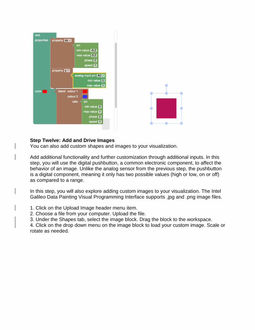
Step Twelve: Add and Drive Images You can also add custom shapes and images to your visualization. Add additional functionality and further customization through additional inputs. In this step, you will use the digital pushbutton, a common electronic component, to affect the behavior of an image. Unlike the analog sensor from the previous step, the pushbutton is a digital component, meaning it only has two possible values (high or low, on or off) as compared to a range. In this step, you will also explore adding custom images to your visualization. The Intel Galileo Data Painting Visual Programming Interface supports .jpg and .png image files. 1. Click on the Upload Image header menu item. 2. Choose a file from your computer. Upload the file. 3. Under the Shapes tab, select the image block. Drag the block to the workspace. 4. Click on the drop down menu on the image block to load your custom image. Scale or rotate as needed.
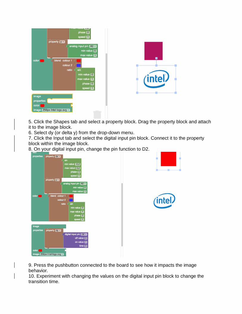
5. Click the Shapes tab and select a property block. Drag the property block and attach it to the image block. 6. Select dy (or delta y) from the drop-down menu. 7. Click the Input tab and select the digital input pin block. Connect it to the property block within the image block. 8. On your digital input pin, change the pin function to D2.
9. Press the pushbutton connected to the board to see how it impacts the image behavior. 10. Experiment with changing the values on the digital input pin block to change the transition time.
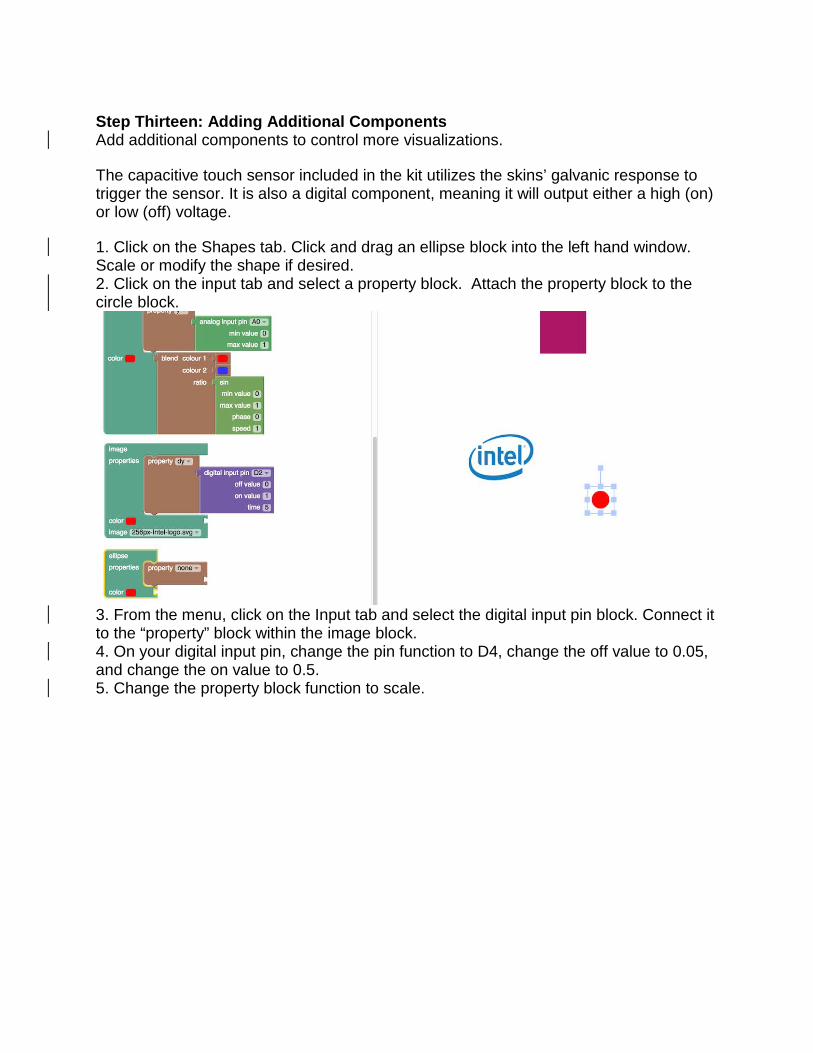
Step Thirteen: Adding Additional Components Add additional components to control more visualizations. The capacitive touch sensor included in the kit utilizes the skins’ galvanic response to trigger the sensor. It is also a digital component, meaning it will output either a high (on) or low (off) voltage. 1. Click on the Shapes tab. Click and drag an ellipse block into the left hand window. Scale or modify the shape if desired. 2. Click on the input tab and select a property block. Attach the property block to the circle block.
3. From the menu, click on the Input tab and select the digital input pin block. Connect it to the “property” block within the image block. 4. On your digital input pin, change the pin function to D4, change the off value to 0.05, and change the on value to 0.5. 5. Change the property block function to scale.
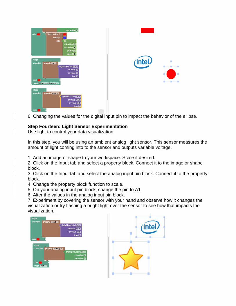
6. Changing the values for the digital input pin to impact the behavior of the ellipse. Step Fourteen: Light Sensor Experimentation Use light to control your data visualization. In this step, you will be using an ambient analog light sensor. This sensor measures the amount of light coming into to the sensor and outputs variable voltage. 1. Add an image or shape to your workspace. Scale if desired. 2. Click on the Input tab and select a property block. Connect it to the image or shape block. 3. Click on the Input tab and select the analog input pin block. Connect it to the property block. 4. Change the property block function to scale. 5. On your analog input pin block, change the pin to A1. 6. Alter the values in the analog input pin block. 7. Experiment by covering the sensor with your hand and observe how it changes the visualization or try flashing a bright light over the sensor to see how that impacts the visualization.
Step Fifteen: Create Data Paintings Congratulations! You’ve explored the basics of the Intel Galileo Data Painting Visual Programming Interface! Now it’s up to you to imagine and create innovative data visualizations-- see how you can manipulate different inputs and functions to make something awesome! If you need additional inspiration, click on the Load button at the top of the screen to load pre-created examples you can manipulate and make your own! NOTE: From time to time the Intel Galileo board may continue to serve the visual programming interface but the inputs may fail to register. If this occurs, close the program and restart through genstaller (step seven). You will need to enter the IP address again. What’s Next? 1. Experiment adding additional sensors! DF Robot has a wide array of different types of analog and digital sensors that are compatible with the I/O expansion shield. 2. Repurpose! The I/O expansion shield, inputs, and outputs can be used for all sorts of additional projects. Check out websites like instructables for great project ideas.