Embed Size (px)
Citation preview
Intel Technology Journal Q2, 2001
Preface Lin Chao Editor Intel Technology Journal Today, our homes, offices, and cars are filled with a variety of electronic machines and computers for communication, entertainment, and information. "Ubiquitous computing" has been described as "making many computers available throughout the physical environment, but making them effectively invisible to the user." (IEEE Computer "Hot Topics," October 1993, Mark Weiser.) There is no doubt that there are many, many computers available now in the physical world, but they are not invisible. Moreover, they demand a lot of user attention both to make them work, and to use them. The unifying theme of this Q2, 2001 issue of the Intel Technology Journal is how to unify networking and communications for our homes, offices, and beyond. We examine some of the practical problems of integrating the variety and complexity of devices available today. The papers in this issue also give examples of the work that Intel is doing in the networking and communications area. The future home (the e-Home) promises faster Internet links, networked computers that talk with intelligent appliances, convenience, energy savers, and devices to keep family members entertained and connected. The 1st paper discusses integrated services, such as multi-media, voice, and data services and outlines the challenges of deploying these integrated services over broadband. The 2nd paper looks at the e-Home, specifically how consumer electronic devices and PCs stand vis-à-vis wireless connectivity. The 3rd paper examines how the PC can coordinate activity in the e-Home, by bridging the various home networks and providing the central computing and communication devices. The 4th paper looks at Ultra-Wideband (UWB) technology, which is loosely defined as any wireless transmission that occupies a bandwidth of more than 25% of a center frequency, or more than 1.5GHz. This paper looks at UWB benefits, limitations, and technical challenges when used for high-rate communications. As the boundary between the communication equipment at the network edge and the servers within the data center blurs, the 5th paper describes a system-level architecture for a new communication services tier of the data center.
Copyright © Intel Corporation 2001. This publication was downloaded from http://www.intel.com/. Legal notices at http://www.intel.com/sites/corporate/tradmarx.htm
Next Generation Networks and Communications
By Kevin Kahn Intel Fellow, Director Communications Architecture
Intel Corp.
This Q2, 2001 issue of the Intel Technology Journal focuses on an area of technology of ever growing importance both to Intel and to the industry at large: networking and communications. In particular, it focuses on some of the things that are happening at the edge of the network where a wide variety of devices and services are appearing to make use of the ever faster and ever cheaper core communications capabilities of the Internet.
The word "convergence" is much overused when describing the evolving communications networks, but in this issue we examine some of the practical problems that come from the variety and complexity of devices that are appearing in people's homes and elsewhere. Quite independent of the details of how communications work, people appear to want the function and convenience that phones, fax machines, general Internet access, entertainment services, and a host of new services offer. What is less clear is how all these functions can be deployed and managed effectively for non-expert users. In this context, convergence is not an abstract notion that we aspire to for the sake of neat design, but rather a concrete response to corralling the complexity of these services in a way that will allow average users to enjoy them. The unifying theme of this issue, and indeed of much of Intel's work in this space, is the development and deployment of effective agreements on how products are architected. Sometimes these agreements manifest themselves as official standards blessed by an official body, and sometimes the agreements are simply working
agreements among the key product developers to create products that work together. Either way, these agreements are key elements of creating products that are usable by non-expert users.
One place where an opportunity to improve the utility and manageability of the various services appears to be in creating a central device that can coordinate access to the various networks from the multitude of home devices in a way that simultaneously lowers costs and reduces complexity. This device has been variously called an Integrated Access Device and a Residential Gateway. Whatever one labels it, it has the potential to rationalize services from phone to Internet to television, across whatever providers a user may utilize. Our first paper addresses the definition of this device. The problem of complexity also appears within the home as users begin to connect not just multiple PCs, but a variety of video and audio entertainment devices, and even a host of new devices that can make their existing PCs more valuable by extending their reach. The second and third papers address both the connectivity and functional barriers to enabling what many people have called the e-Home. The second paper looks at how an important wireless networking technology, IEEE 802.11, can be combined with the main digital entertainment interconnection scheme, IEEE 1394, to allow the easy interconnection of groups of A/V and PC devices around a home without needing to deploy new wires or fibers. The third paper looks more generally at the role that the PC can play as a plethora
Next Generation Networks and Communications 1
Intel Technology Journal Q2, 2001
of new devices appear in the home. The role of the Extended PC will be to tie together these devices and their data sources and to manage their complexity, so that users can extract the full benefits from their connected homes. The fourth paper looks at a new class of wireless technology called Ultra Wideband, (UWB) which may turn out to be important for short-range, high-data-rate communications. UWB takes advantage of the exploding amount of digital signal processing now becoming available to replace high-power narrow-band transmission with very low-power but extremely wide-band signals. This technology has great promise, particularly over the short communications distances that many personal devices will need, but faces both technical challenges and regulatory hurdles if it is to succeed. Finally, to deploy the rich variety of services implied in all these papers, the complexity of the server environment at the other edge of the network, namely the service provider's data center, must also be tamed. The last paper in this issue addresses the system architecture needed to allow the scalable, manageable services to actually be deployed using standard, cost-effective building blocks.
Networks today are extremely complex. The explosion of new devices and services being offered to their users will only make them even more complex. To reach their potential in any market, but particularly in the consumer market, networks must be made much more self-configuring and must be automatically managed. Over the long term, Intel expects to drive product and technology development in directions that will continue to simplify the deployment and management of these end-to-end networks. Only by integrating the entire suite of networking technologies within a set of well-designed architectures can Intel, and the rest of the industry, deliver advanced communications
services to consumers who want their benefits without becoming technical experts. We hope that the set of papers in this issue can provide some insight into the breadth of network and communications issues that are being addressed at Intel and elsewhere. Achieving a usable network that stretches from the service provider all the way to the new mobile devices in the home will require combining technologies ranging from basic radio processing to high-level system architecture, all disciplines in which Intel is heavily invested. These papers should give some examples of how Intel is working to deliver on the promises of these technologies.
Copyright © Intel Corporation 2001. This publication was downloaded from http://www.intel.com/. Legal notices at http://www.intel.com/sites/corporate/tradmarx.htm
Next Generation Networks and Communications 2
Open CPE Architecture: A Solution to the Delivery of Integrated Services over Broadband 1
Open CPE Architecture: A Solution to the Delivery of Integrated Services over Broadband
Joey Chou, Intel Communications Group, Intel Corp.
Index words: CPE, RG, IAD, CPL, NGN, integrated services over Broadband, open CPE Architecture
ABSTRACT
Over the decades, due to technology limitations and regulatory restrictions, information services have been delivered to subscribers through multiple service providers. In recent years, however, the advancement of digital communication technology, the passing of the 1996 Telecommunications Act in the U.S., and the emergence of the Internet are driving network convergence. As a result, the industry is calling for the consolidation of an integrated Customer Premises Equipment (CPE) in the customer’s premises to provide integrated services, such as multi-media, voice, and data services. However, the ever-changing network standards and competing technologies not only confuse carriers, but also prevent them from committing to massive CPE deployment.
In this paper, the problems carriers face in the deployment of integrated services over broadband are first described. In order to remove these deployment obstacles, and also to create new value-added services, service models are investigated and an open CPE architecture is proposed that will support the wide range of broadband access technologies and ever-changing network standards.
For your reference, an Appendix of acronyms used in this paper is included.
INTRODUCTION Over the decades, due to technology limitations and regulatory restrictions, information services have been delivered to subscribers through multiple service providers via twisted-pair copper, coax cable, terrestrial wireless, satellite, and fiber optics. As a result, houses are filled with multiple Customer Premises Equipment (CPE) such as POTS (Plain Old Telephone System) phones, cordless phones, fax machines, answering
machines, set-top-box, Caller ID receivers, and Direct Broadcast Satellite (DBS) receivers, etc., and the sophisticated wiring necessary to connect them. Not only is it deemed too troublesome for subscribers to use and manage all these devices, but it is also not cost-effective, as network resources are not efficiently used.
In recent years, however, there have been tremendous changes in the telecommunication industry. First, the advancement of digital communication technology paved the way for service integration. Then, the passing of the 1996 Telecommunications Act in the U.S. unleashed competition among phone carriers and cable TV service providers. However, it was the emergence of the Internet that created the largest impact on the telecommunication networks by bringing about the convergence of voice and Internet data traffic. Consequently, carriers and service providers are overhauling the entire network infrastructure–including switches, routers, backbone, and the last mile (i.e., the local loop)–in an effort to improve Internet access performance without degrading voice services.
This convergence of voice and Internet data traffic also calls for new Customer Premises Equipment (CPE) such as Digital Subscriber Lines (DSLs), modems, cable modems, and wireless modems that provide users with broadband access to the Internet. However, instead of adding new CPE to the home, the industry is moving towards consolidating CPE into an Integrated CPE (I-CPE) to help lower the cost, reduce network management complexities, and improve the efficiency of network resources. The I-CPE is also called an Integrated Access Device (IAD) and a Residential Gateway (RG) when used in residential areas. In this paper, the term I-CPE is used, because I-CPE is intended to serve multiple market segments including residential, Small Office Home Office (SOHO), and small businesses to provide integrated services such as voice, multi-media, and Internet access.
Intel Technology Journal Q2, 2001
Open CPE Architecture: A Solution to the Delivery of Integrated Services over Broadband 2
While the upgrade of the network infrastructure is well underway, the deployment of I-CPE remains a big obstacle to the delivery of integrated services over broadband due to the volume and time that are required for the deployment. It was believed that the lack of auto-configuration was the main roadblock to massive I-CPE deployment. However, the largest obstacle today is not so much how to deploy I-CPE but rather, which type of I-CPE the carriers should be deploying, because this telecommunication world is filled with too many standards, e.g., Media Gateway Control Protocol (MGCP), H.248 [7], H.323, Session Initiation Protocol (SIP), Voice over Internet Protocol (VoIP), Voice over ATM (VoATM), etc.; and competing technologies, e.g., DSL, Cable, Wireless, Fiber, Ethernet, HomeRF∗, IEEE 802.11, Bluetooth*, etc. As a result, carriers are facing great difficulties in choosing an I-CPE for deployment because they fear it being replaced in the near future.
The objective of this paper is to provide a solution to the I-CPE deployment dilemma. The paper is therefore organized as follows. I first look into the history and regulations of CPE deployment to project the appropriate model for the rollout of I-CPE and its services. I then describe the big picture of the Next-Generation Network (NGN) infrastructure and the role of I-CPE in the NGN. The requirements for I-CPE are then defined, and an open CPE architecture is proposed. Finally, I discuss the challenges associated with open CPE deployment.
SERVICE MODELS The most well known Customer Premises Equipment (CPE) in the telecommunication industry is probably the telephone equipment found in subscribers’ residences. This century-old telephone equipment has gone through many changes, most noticeably the 1975 U.S. government mandate to open the phone interface, which allowed subscribers to buy phones from any retail store. Deregulation of the telephone equipment was a turning point leading to the divestiture of the Bell Operating Company in 1982 and the privatization of government-owned telephone enterprises around the world later on. In addition, deregulation also enabled the creation of advanced services, such as the facsimile, modem, answering machine, Caller ID, and the cordless phone. The need for interoperability among telecommunication equipment of multiple carriers triggered the formation of new telephony standards, such as SONET, SS7, GR-303, Integrated Services Digital Networks (ISDN), and Advanced Intelligent Networks (AIN).
∗ Other names and brands may be claimed as the property of others.
The set-top box is another CPE commonly found in subscribers’ residences. It is distinct from telephone equipment in that video content signals are broadcast to subscribers. Therefore, the set-top box is normally owned by CATV operators in order to prevent subscribers from viewing videos that they have not paid for. However, the OpenCable* initiative, sponsored by leading cable TV companies and managed by CableLabs, is looking at opening up the cable interface and creating a new business model that will allow customers to purchase set-top boxes from retailers [11].
Today, xDSL and cables are the two most widespread broadband interfaces that I-CPE should support in order to provide integrated services over broadband. The regulation changes and evolution of both phone and cable interfaces of the past provide very few guidelines as to what model I-CPE should adopt: I-CPE is such a new device that we still do not understand its capability completely. It is certain, however, that I-CPE will not be based on a proprietary interface or on a design controlled by a handful of service providers [1]. It is also clear that the broadband CPE model will most likely be driven by competition in the marketplace and the industry’s open forums, as opposed to government regulations.
The phenomenal growth of Internet hosts in households around the world in the past few years has in part been attributed to the open interface standard and easy purchase and installation of dial-up modems. Therefore, it is believed that an open standard for the broadband interface should be mandatory for I-CPE to be accepted in the market place, and subscribers should be able to own and install I-CPE in order for it to be deployed massively and rapidly.
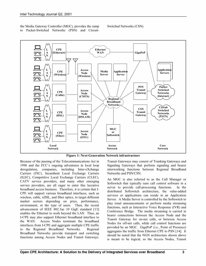
THE NEXT-GENERATION NETWORK INFRASTRUCTURE Unlike the dial-up modem, the introduction of I-CPE will require major upgrades in the infrastructure of the existing network. The new network is intended to support the convergence of the voice-centric Public Switched Telephone Network (PSTN) and the Internet, and it is commonly referred as the Next-Generation Network (NGN). The NGN is based on the distributed Softswitch architecture in which the call control is separated from the media transport. Figure 1 shows the role of I-CPE in the NGN infrastructure. It indicates that an I-CPE is the portal to a customer’s premises and it acts as the gateway to interconnect the Local Area Network (LAN) with the Wide Area Network (WAN), which consist of the Access Network and the Core Network [6]. The Access Network, consisting of Access Nodes, Regional Broadband Networks, Transit Gateways, and
Intel Technology Journal Q2, 2001
Open CPE Architecture: A Solution to the Delivery of Integrated Services over Broadband 3
the Media Gateway Controller (MGC), provides the ramp to Packet-Switched Networks (PSN) and Circuit-
Switched Networks (CSN).
CoreNetwork
AccessNetwork
LocalNetwork
RegionalBroadbandNetworks
CircuitSwitchedNetworks(PSTN)
CPE(Cable)
AccessNode
(CMTS)
CSNTransit
GatewayCPE
(DSL)
AccessNode
(DSLAM)
CPE(Wireless)
AccessNode
(Wireless)
LAN
PacketSwitchedNetworks(Internet)
PSNTransit
Gateway
CPE(Fiber)
AccessNode
(ONU)
LAN
LAN
LAN
MGCor
Softswitch
ApplicationServersApplication
ServerMediaServer
CPE(Ethernet) GigaPoP
LAN
EthernetWAN
Figure 1: Next-Generation Network infrastructure
Because of the passing of the Telecommunications Act in 1996 and the FCC’s ongoing adventures in local loop deregulation, companies, including Inter-eXchange Carriers (IXC), Incumbent Local Exchange Carriers (ILEC), Competitive Local Exchange Carriers (CLEC), CATV service providers, and many other emerging service providers, are all eager to enter this lucrative broadband access business. Therefore, it is certain that I-CPE will support various broadband interfaces, such as wireless, cable, xDSL, and fiber optics, to target different market sectors depending on price, performance, environment, or the type of users. Then, the recent advancement of IEEE 802.3ae 10 GigE standard [13] enables the Ethernet to work beyond the LAN. Thus, an I-CPE may also support Ethernet broadband interface to the WAN. Access Nodes terminate the broadband interfaces from I-CPE and aggregate multiple CPE traffic to the Regional Broadband Networks. Regional Broadband Networks provide transport and switching functions among Access Nodes and Transit Gateways.
Transit Gateways may consist of Trunking Gateways and Signaling Gateways that perform signaling and bearer interworking functions between Regional Broadband Networks and PSN/CSN.
An MGC is also referred to as the Call Manager or Softswitch that typically runs call control software in a server to provide call-processing functions. In the distributed Softswitch architecture, the value-added services or applications can reside in an Application Server. A Media Server is controlled by the Softswitch to play tonal announcements or perform media streaming functions, such as Interactive Voice Response (IVR) and Conference Bridge. The media streaming is carried in bearer connections between the Access Node and the Transit Gateway for on-net calls, or between Access Nodes for off-net calls, while call control functions are provided by an MGC. GigaPoP (i.e., Point of Presence) aggregates the traffic from Ethernet CPE to PSN [14]. It should be noted that the NGN architecture shown above is meant to be logical, so the Access Nodes, Transit
Intel Technology Journal Q2, 2001
Open CPE Architecture: A Solution to the Delivery of Integrated Services over Broadband 4
Gateways, Media Server, Application Server, and MGC are logical functional blocks which may be implemented as stand-alone devices or embedded in other network elements.
OPEN CPE ARCHITECTURE Broadband access is, for many, the solution to the “World Wide Wait” problem (slow Web performance), and it would also enable the creation of many new services that promise enormous benefits to subscribers and service providers. However, service providers are facing many challenges during the deployment of broadband access networks, not least of which is how to deploy the greatest number of Customer Premises Equipment (CPE) in the timeliest manner.
I-CPE Characteristics The following characteristics of the Integrated Customer Premises Equipment (I-CPE) architecture are important to the resolution of these deployment problems.
• Open Architecture–In the past several decades, open architecture has become the trend in the industry. It started with the computer industry in the early 80s, and it gradually spread to the telecommunication industry, where the monolithic central office switch is under great pressure from the Internet telephony to open up. The broadband CPE industry will not buck this trend since openness will only foster new services and product competition, which, in turn, will lower CPE cost, reduce time-to-market, and inspire innovation [3].
• Flexibility–The ever-changing network standards and infrastructures, the wide range of access network technologies, and the uncertainty of which value-added service will emerge in the future make it very difficult to have a fit-it-all CPE architecture. Thus, the I-CPE should be flexible to contain the must-have core features needed to support today’s services, yet it should still be able to accommodate future upgrades. Flexible architecture will lower CPE costs, something that is crucial to I-CPE being accepted in the cost-sensitive consumer market. For example, an I-CPE might be designed to provide home automation and security services, but the interface standards as well as the functionalities to control home appliances have yet to be defined. The flexible architecture needs to be able to accommodate a Bluetooth∗ wireless modem plug-in
∗ Other names and brands may be claimed as the property of others.
and the necessary software that will need to be added to the CPE to support this feature when the standard and technology become available.
• Value-Added Services–Each time a new service or technology is introduced, it needs to be perceived by the public as adding value in order that it will be bought and used. Due to the competition from Internet telephony, the cost of toll telephony services is continually decreasing. Soon, it is believed, you will be charged a flat monthly rate for telephone services instead of being billed on a per-minute basis. Therefore, the driver for the Next-Generation Network (NGN) is not about inventing a new way to provide existing services, but focusing on value-added services such as Presence, Voice Web, Voice Portal, Unified Messaging, and Voice Virtual Private Network (VPN), which hold great potential for generating additional revenue for service providers.
• CPE Ownership–Direct Broadcast Satellite (DBS) successfully achieved the goal of one million units of deployment in the shortest time interval ever in the U.S., while the cellular phone market has grown to 600 million subscribers worldwide in just about a decade. Both DBS and cellular phones adopted the model of asking the subscriber to purchase CPE. The opening up of the I-CPE architecture further decouples the strong tie between CPE and service providers and should allow people to receive services from multiple service providers. This decoupling will also enable the creation of new services via third-party applications. All these things imply that I-CPE should not be owned by service providers but by the customers. Moreover, this ownership model should also lead to the self-installation and provisioning of I-CPE, which, as mentioned, is considered mandatory for massive CPE deployment.
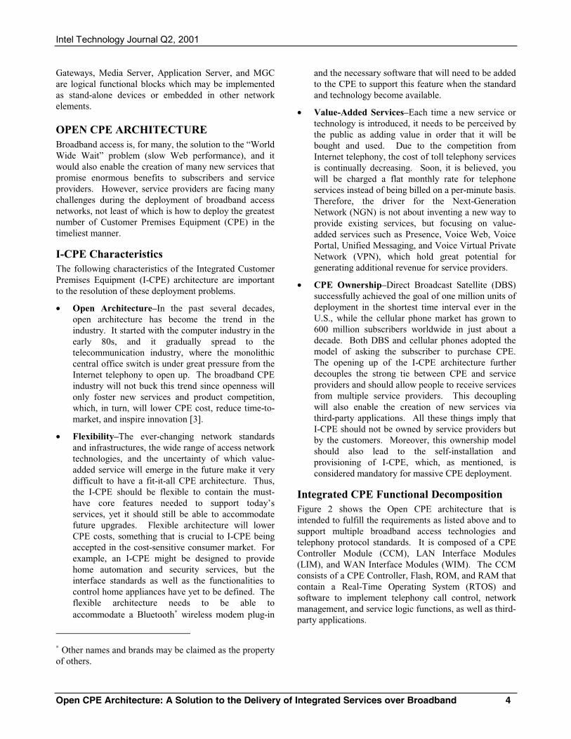
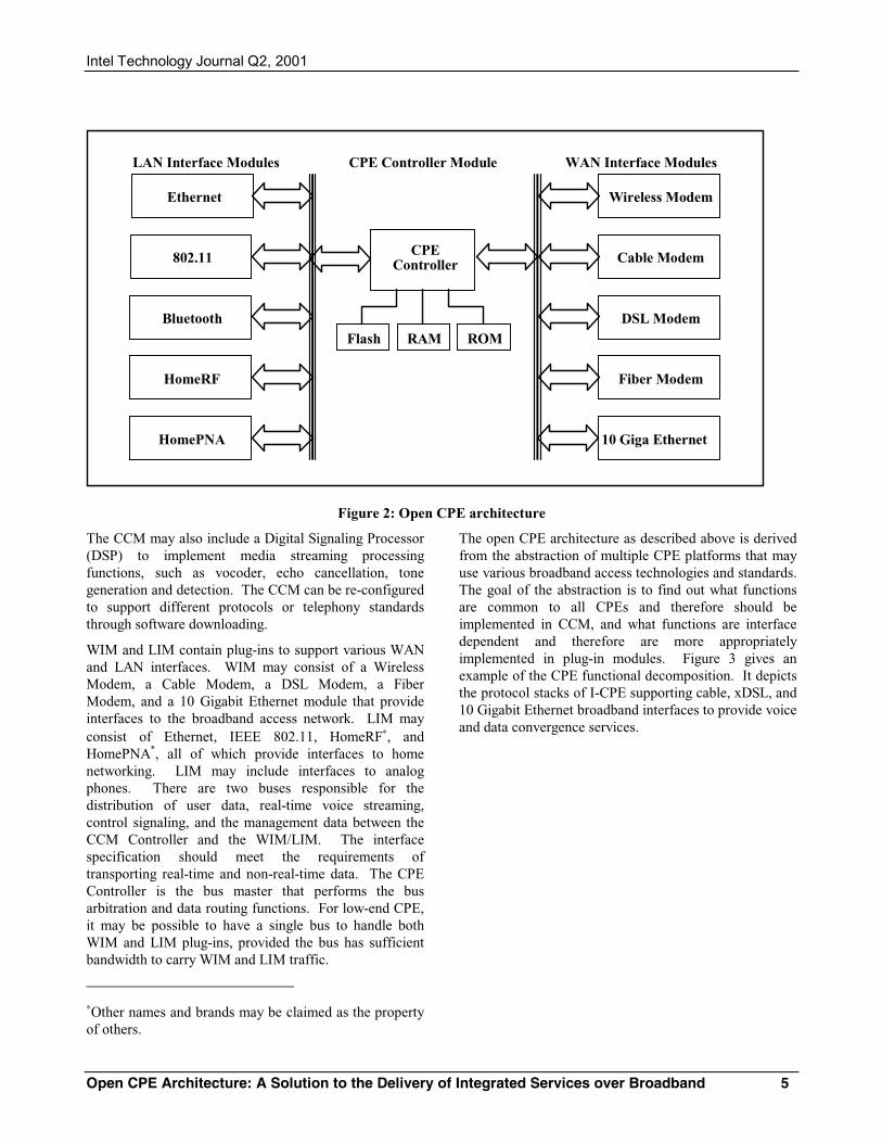
Integrated CPE Functional Decomposition Figure 2 shows the Open CPE architecture that is intended to fulfill the requirements as listed above and to support multiple broadband access technologies and telephony protocol standards. It is composed of a CPE Controller Module (CCM), LAN Interface Modules (LIM), and WAN Interface Modules (WIM). The CCM consists of a CPE Controller, Flash, ROM, and RAM that contain a Real-Time Operating System (RTOS) and software to implement telephony call control, network management, and service logic functions, as well as third-party applications.
Intel Technology Journal Q2, 2001
Open CPE Architecture: A Solution to the Delivery of Integrated Services over Broadband 5
Wireless Modem
CPEController
Flash
LAN Interface Modules
Cable Modem
DSL Modem
Fiber Modem
RAM ROM
Ethernet
802.11
Bluetooth
HomeRF
WAN Interface ModulesCPE Controller Module
10 Giga EthernetHomePNA
Figure 2: Open CPE architecture
The CCM may also include a Digital Signaling Processor (DSP) to implement media streaming processing functions, such as vocoder, echo cancellation, tone generation and detection. The CCM can be re-configured to support different protocols or telephony standards through software downloading.
WIM and LIM contain plug-ins to support various WAN and LAN interfaces. WIM may consist of a Wireless Modem, a Cable Modem, a DSL Modem, a Fiber Modem, and a 10 Gigabit Ethernet module that provide interfaces to the broadband access network. LIM may consist of Ethernet, IEEE 802.11, HomeRF∗, and HomePNA*, all of which provide interfaces to home networking. LIM may include interfaces to analog phones. There are two buses responsible for the distribution of user data, real-time voice streaming, control signaling, and the management data between the CCM Controller and the WIM/LIM. The interface specification should meet the requirements of transporting real-time and non-real-time data. The CPE Controller is the bus master that performs the bus arbitration and data routing functions. For low-end CPE, it may be possible to have a single bus to handle both WIM and LIM plug-ins, provided the bus has sufficient bandwidth to carry WIM and LIM traffic.
∗Other names and brands may be claimed as the property of others.
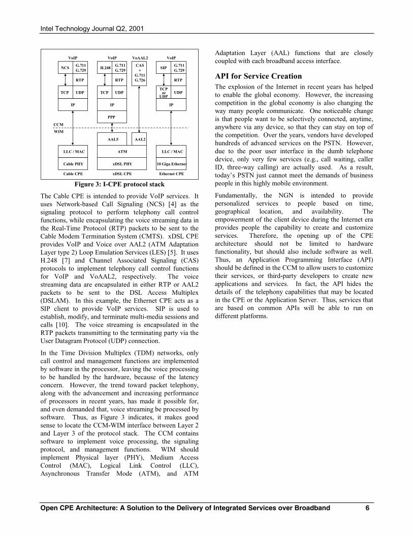
The open CPE architecture as described above is derived from the abstraction of multiple CPE platforms that may use various broadband access technologies and standards. The goal of the abstraction is to find out what functions are common to all CPEs and therefore should be implemented in CCM, and what functions are interface dependent and therefore are more appropriately implemented in plug-in modules. Figure 3 gives an example of the CPE functional decomposition. It depicts the protocol stacks of I-CPE supporting cable, xDSL, and 10 Gigabit Ethernet broadband interfaces to provide voice and data convergence services.
Intel Technology Journal Q2, 2001
Open CPE Architecture: A Solution to the Delivery of Integrated Services over Broadband 6
xDSL CPE
xDSL PHY
ATM
AAL2AAL5
PPP
CAS+
G.711G.726
G.711G.729
Cable PHY
LLC / MAC
IP
RTP
UDPTCP
NCSG.711G.729
IP
RTP
UDPTCP
H.248
Cable CPE
VoIP VoIP VoAAL2
CCM
WIM
TCP or
UDP
G.711G.729
10 Giga Ethernet
LLC / MAC
IP
RTP
UDP
SIP
Ethernet CPE
VoIP
Figure 3: I-CPE protocol stack
The Cable CPE is intended to provide VoIP services. It uses Network-based Call Signaling (NCS) [4] as the signaling protocol to perform telephony call control functions, while encapsulating the voice streaming data in the Real-Time Protocol (RTP) packets to be sent to the Cable Modem Termination System (CMTS). xDSL CPE provides VoIP and Voice over AAL2 (ATM Adaptation Layer type 2) Loop Emulation Services (LES) [5]. It uses H.248 [7] and Channel Associated Signaling (CAS) protocols to implement telephony call control functions for VoIP and VoAAL2, respectively. The voice streaming data are encapsulated in either RTP or AAL2 packets to be sent to the DSL Access Multiplex (DSLAM). In this example, the Ethernet CPE acts as a SIP client to provide VoIP services. SIP is used to establish, modify, and terminate multi-media sessions and calls [10]. The voice streaming is encapsulated in the RTP packets transmitting to the terminating party via the User Datagram Protocol (UDP) connection.
In the Time Division Multiplex (TDM) networks, only call control and management functions are implemented by software in the processor, leaving the voice processing to be handled by the hardware, because of the latency concern. However, the trend toward packet telephony, along with the advancement and increasing performance of processors in recent years, has made it possible for, and even demanded that, voice streaming be processed by software. Thus, as Figure 3 indicates, it makes good sense to locate the CCM-WIM interface between Layer 2 and Layer 3 of the protocol stack. The CCM contains software to implement voice processing, the signaling protocol, and management functions. WIM should implement Physical layer (PHY), Medium Access Control (MAC), Logical Link Control (LLC), Asynchronous Transfer Mode (ATM), and ATM
Adaptation Layer (AAL) functions that are closely coupled with each broadband access interface.
API for Service Creation The explosion of the Internet in recent years has helped to enable the global economy. However, the increasing competition in the global economy is also changing the way many people communicate. One noticeable change is that people want to be selectively connected, anytime, anywhere via any device, so that they can stay on top of the competition. Over the years, vendors have developed hundreds of advanced services on the PSTN. However, due to the poor user interface in the dumb telephone device, only very few services (e.g., call waiting, caller ID, three-way calling) are actually used. As a result, today’s PSTN just cannot meet the demands of business people in this highly mobile environment.
Fundamentally, the NGN is intended to provide personalized services to people based on time, geographical location, and availability. The empowerment of the client device during the Internet era provides people the capability to create and customize services. Therefore, the opening up of the CPE architecture should not be limited to hardware functionality, but should also include software as well. Thus, an Application Programming Interface (API) should be defined in the CCM to allow users to customize their services, or third-party developers to create new applications and services. In fact, the API hides the details of the telephony capabilities that may be located in the CPE or the Application Server. Thus, services that are based on common APIs will be able to run on different platforms.
Intel Technology Journal Q2, 2001
Open CPE Architecture: A Solution to the Delivery of Integrated Services over Broadband 7
CCM
Media Transport
Third-PartyApplications
XML, CPL, CGI
Call Control
Bearer Control
Service Layer
WebApplications
ManualEditing
WIM
API
Figure 4: I-CPE Service Creation Model
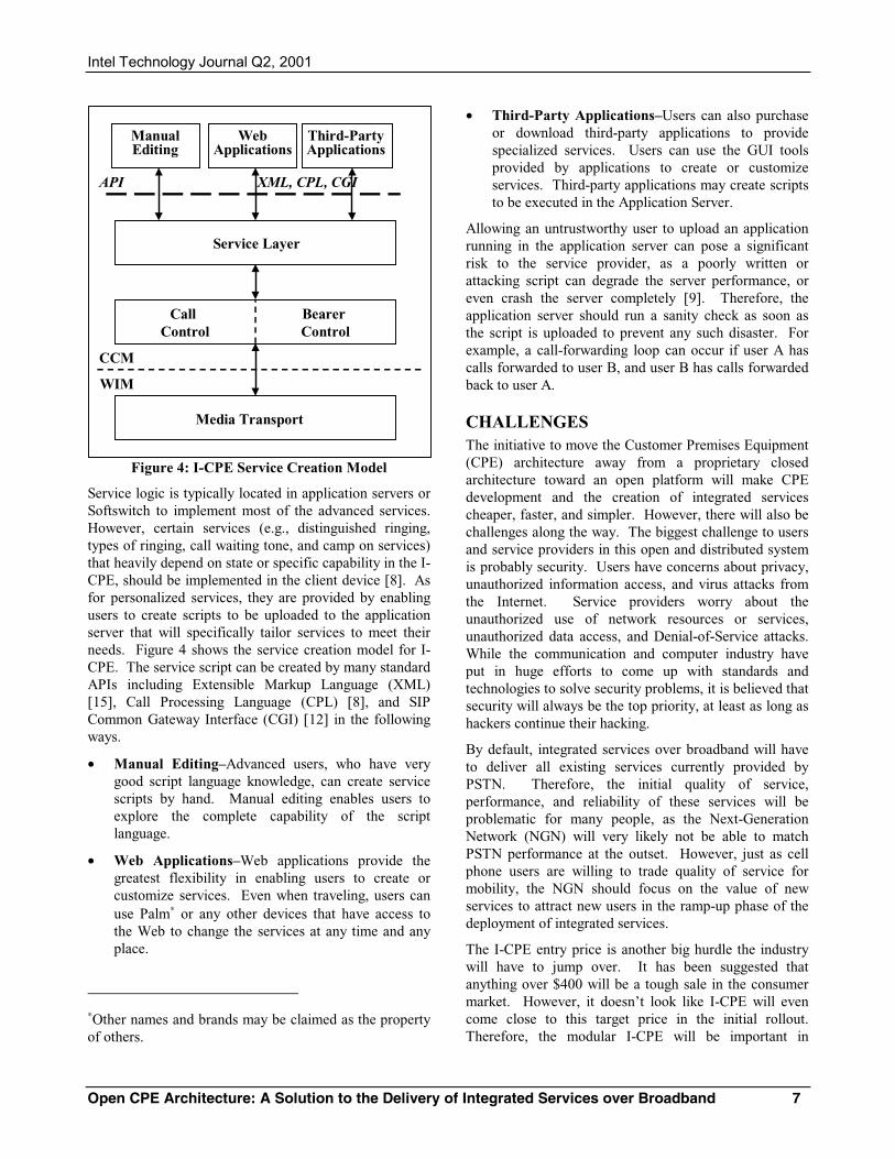
Service logic is typically located in application servers or Softswitch to implement most of the advanced services. However, certain services (e.g., distinguished ringing, types of ringing, call waiting tone, and camp on services) that heavily depend on state or specific capability in the I-CPE, should be implemented in the client device [8]. As for personalized services, they are provided by enabling users to create scripts to be uploaded to the application server that will specifically tailor services to meet their needs. Figure 4 shows the service creation model for I-CPE. The service script can be created by many standard APIs including Extensible Markup Language (XML) [15], Call Processing Language (CPL) [8], and SIP Common Gateway Interface (CGI) [12] in the following ways.
• Manual Editing–Advanced users, who have very good script language knowledge, can create service scripts by hand. Manual editing enables users to explore the complete capability of the script language.
• Web Applications–Web applications provide the greatest flexibility in enabling users to create or customize services. Even when traveling, users can use Palm∗ or any other devices that have access to the Web to change the services at any time and any place.
∗Other names and brands may be claimed as the property of others.
• Third-Party Applications–Users can also purchase or download third-party applications to provide specialized services. Users can use the GUI tools provided by applications to create or customize services. Third-party applications may create scripts to be executed in the Application Server.
Allowing an untrustworthy user to upload an application running in the application server can pose a significant risk to the service provider, as a poorly written or attacking script can degrade the server performance, or even crash the server completely [9]. Therefore, the application server should run a sanity check as soon as the script is uploaded to prevent any such disaster. For example, a call-forwarding loop can occur if user A has calls forwarded to user B, and user B has calls forwarded back to user A.
CHALLENGES The initiative to move the Customer Premises Equipment (CPE) architecture away from a proprietary closed architecture toward an open platform will make CPE development and the creation of integrated services cheaper, faster, and simpler. However, there will also be challenges along the way. The biggest challenge to users and service providers in this open and distributed system is probably security. Users have concerns about privacy, unauthorized information access, and virus attacks from the Internet. Service providers worry about the unauthorized use of network resources or services, unauthorized data access, and Denial-of-Service attacks. While the communication and computer industry have put in huge efforts to come up with standards and technologies to solve security problems, it is believed that security will always be the top priority, at least as long as hackers continue their hacking.
By default, integrated services over broadband will have to deliver all existing services currently provided by PSTN. Therefore, the initial quality of service, performance, and reliability of these services will be problematic for many people, as the Next-Generation Network (NGN) will very likely not be able to match PSTN performance at the outset. However, just as cell phone users are willing to trade quality of service for mobility, the NGN should focus on the value of new services to attract new users in the ramp-up phase of the deployment of integrated services.
The I-CPE entry price is another big hurdle the industry will have to jump over. It has been suggested that anything over $400 will be a tough sale in the consumer market. However, it doesn’t look like I-CPE will even come close to this target price in the initial rollout. Therefore, the modular I-CPE will be important in
Intel Technology Journal Q2, 2001
Open CPE Architecture: A Solution to the Delivery of Integrated Services over Broadband 8
bringing down the cost. Moreover, we will need to count on highly integrated chip sets to further reduce the cost.
Considering the time it took to build PSTN, it is the concern of many that it will take too long to deploy integrated services over broadband. Thus, self-installation, provisioning, and auto-configuration should be mandatory for broadband deployment. The question arises then as to who will be responsible when problems surface during installation or regular operation. There may not be a concrete answer to this problem. One thing we seem certain of is that I-CPE should have very good diagnostic capabilities that will enable service providers to diagnose and even fix problems remotely. A certain service provider may take primary responsibility for the I-CPE operation, while other service providers need only take responsibility for services they provide. It is also possible that a third-party IT company may take over the I-CPE maintenance business. As a matter of fact, there are companies out there today whose sole jobs are to manage the network operations for Competitive Local Exchange Carriers (CLEC).
CONCLUSION The explosion of the Internet along with regulation and technology changes are reshaping telecommunication networks in many ways. The industry is moving toward the convergence of PSTN and the Internet. The converged network, the NGN, will operate in a very similar way to the Internet topology in which central office switches are decomposed into distributed systems that are based on the Softswitch model. As a result, the NGN will no longer provide transport services between telephone equipment (as PSTN previously did), but will provide personalized multi-media services. This convergence of voice and Internet data traffic also calls for the deployment of I-CPE to provide integrated services.
However, the ever-changing network standards and competing technologies not only confuse carriers, but also prevent them from committing to massive CPE deployment, because they are afraid that the CPE just deployed will have to be replaced in a few years. Hardware replacement is very common in the PC and cellular phone business when new standards or technologies are introduced, but it presents a big threat to the wireline broadband business because CPE deployment is such a daunting task that it cannot be completed easily.
In this paper, I proposed an open CPE architecture to solve the CPE deployment dilemma. The architecture is very flexible and can support multiple WAN/LAN technologies and IP Telephony standards. It also
includes a common API to allow users to customize or even create new services and third-party developers to create new applications and services. The open CPE architecture will allow CPE vendors to lower costs and reduce time-to-market, and most importantly enable service providers to provide many value-added services that promise great potential for generating additional revenue.
ACKNOWLEDGMENTS The author acknowledges Hach Nguyen for helpful comments and discussions, Jeff Lawrence, Nabil Damouny, and Ravi Bhat for providing valuable comments, and Lin Chao, the editor of this journal, for comments and suggestions.
REFERENCES [1]C. A. Eldering, “Customer Premises Equipment for
Residential Broadband Gateway,” IEEE Communication Magazine, June 1997, pp. 114-121.
[2]S. Moyer and A. Umar, “The Impact of Network Convergence on Telecommunications Software,” IEEE Communication Magazine, January 2001, pp. 78-84.
[3]C. Low, “Integrating Communication Services,” IEEE Communication Magazine, June 1997, pp. 164-169.
[4]“PacketCable Network-based Call Signaling Protocol Specification,” Pkt-SP-EC-MGCP-101-990312, Cable Lab, 3/12/1999.
[5]“Voice and Multimedia over ATM–Loop Emulation Service Using AAL2,” af-vmoa-145.000, ATM Forum, July 2000.
[6]J. Chou, “The migration of LES to the Next Generation Network based on H.248,” ATM Forum, atm00-164, San Francisco, May 2000.
[7]F. Cuervo, N. Greene, A. Rayhan, C. Huitema, B. Rosen, and J. Segers. “Megaco Protocol Version 1.0,” IETF RFC3015, November 2000.
[8]J. Lennox, H. Schulzrinne, “Call Processing Language Framework and Requirements,” IETF RFC2824, May 2000.
[9]J. Rosenberg, J. Lennox, H. Schulzrinne, “Programming Internet Telephony Services,” IEEE Internet Computing, May-June 1999, pp. 63-72.
[10]M. Handley, H. Schulzrinne, E. Schooler, and J. Rosenberg, “SIP: Session Initiation Protocol,” IETF, RFC2543, March 1999.
Intel Technology Journal Q2, 2001
Open CPE Architecture: A Solution to the Delivery of Integrated Services over Broadband 9
[11]“OpenCable™,” http://www.opencable.com, Cable Labs.
[12]J. Lennox, H. Schulzrinne, J. Rosenberg, “Common Gateway Interface for SIP,” IETF RFC3050, January 2001.
[13]IEEE P802.3ae 10Gb/s Ethernet Task Force, http://grouper.ieee.org/groups/802/3/ae/index.html
[14]“Lighting Internet in the WAN,” Telecommunication Magazine, September, 2000, http://telecoms-mag.com/issues/200009/tcs/lighting_internet.html
[15]“Extensible Markup Language,” W3C World Wide Web Consortium, http://www.w3.org/XML/
APPENDIX–ACRONYMS USED IN THIS PAPER AAL ATM Adaption Layer
AIN Advanced Intelligent Networks
API Application Programming Interface
ATM Asynchronous Transfer Mode
CAS Channel Associated Signaling
CCM CPE Controller Module
CGI Common Gateway Interface
CGI Common Gateway Interface
CLEC Competitive Local Exchange Carriers
CMTS Cable Modem Termination System
CPE Customer Premises Equipment
CPL Call Processing Language
CSN Circuit-Switched Networks
DBS Direct Broadcast Satellite
DSP Digital Signal Processor
DSL Digital Subscriber Line
IAD Integrated Access Device
ILEC Incumbent Local Exchange Carriers
ISDN Integrated Services Digital Networks
IVR Interactive Voice Response
IXC Inter-eXchange Carriers
LAN Local Area Network
LES Loop Emulation Services
LIM LAN Interface Module
LLC Logical Link Control
MAC Medium Access Control
MGC Media Gateway Controller
MGCP Media Gateway Control Protocol
NCS Network-based Call Signaling
NGN Next-Generation Network
PHY Physical layer
POTS Plain Old Telephone System
PSN Packet-Switched Networks
PSTN Public Switched Telephone Network
RG Residential Gateway
RTOS Real-Time Operating System
RTP Real-Time Protocol
SIP Session Initiation Protocol
SOHO Small Office Home Office
TDM Time Division Multiplex
UDP User Datagram Protocol
VoATM Voice over ATM
VoIP Voice over Internet Protocol
VPN Virtual Private Network
WAN Wide Area Network
WIM WAN Interface Module
XML Extensible Markup Language
AUTHOR’S BIOGRAPHY Joey Chou is a System Architect in Intel’s Platform Network Group, responsible for driving the solutions for voice + data over broadband. He has 20 years telecommunication experience working on the development of No.5 ESS, DLC, FTTC, HFC, and Iridium and Teledesic Satellite Communication Systems. Prior to joining Intel in 1999, he worked at GTE, Siemens, AT&T, and Motorola. Joey is a key contributor to the VoDSL standard work in the ATM and DSL Forums. His current research interest is in the evolution of PSTN to NGN. He received a Bachelor’s degree in Electrical Engineering from the National Taiwan Institute
Intel Technology Journal Q2, 2001
Open CPE Architecture: A Solution to the Delivery of Integrated Services over Broadband 10
of Technology and a Master’s degree in Electrical Engineering from Georgia Institute of Technology in 1985. His e-mail address is [email protected].
Copyright © Intel Corporation 2001. This publication was downloaded from http://developer.intel.com/.
Legal notices at http://developer.intel.com/sites/developer/tradmarx.htm.
Wireless Convergence of PC and Consumer Electronics in the e-Home 1
Wireless Convergence of PC and Consumer Electronics in the e-Home
Steve Bard, Connected and Extended PC Lab, Intel Corp.
Index words: e-Home, 1394, 802.11e, 802.11a, CE, Extended PC, home network, wireless
ABSTRACT
The vision of the electronically connected digital home from the perspective of the Consumer Electronics (CE) and Personal Computer (PC) industries would be nearly identical except for one very important distinction: the consumer electronics industry presentation would not include a PC as a necessary component of the home.
There is a goal to replace the plethora of “spaghetti” cabling typically found in the back of home entertainment centers with a single, high-speed, peer-to-peer digital wire. This wire facilitates delivery of digital multi-media content and device configuration/control between the devices. The CE industry has selected the High Performance Serial Bus (IEEE 1394-1995 and its amendments, IEEE 1394a-2000 and IEEE P1394b) as the preferred interconnect between digital consumer devices. The CE industry is developing its plan to deliver Internet content and services from an Internet broadband connection to CE devices and appliances via a 1394 connected Set-Top Box (STB). With the incorporation of the Internet Protocol (IP) into 1394, a seamless peer-to-peer network of CE devices is created. This network of devices and appliances is referred to as the Consumer Entertainment Network (Ce-Net).
A wireless connectivity solution is presented that enables interoperability between the Ce-Net and the PC. Methods are presented in which content traditionally reserved for delivery over a wired 1394 network is delivered over an IEEE 802.11a/e WLAN–bridging 1394 to 802.11.
The PC, and its connectivity infrastructure, is in an excellent position to enhance the consumer’s experience in the e-Home environment by offering CE device connectivity and configuration/control. The PC is capable of providing proxy service to enhance the capability of consumer devices. It has an opportunity to be a key player in the e-Home. This paper presents interconnect and protocol issues currently faced by the CE industry and describes how the PC is well suited to resolve them. It shows how the PC can successfully fit into the e-Home,
providing opportunities for new applications and services that would not be possible otherwise.
Appendices A and B, which define the terms and acronyms used in this paper, are found at the end of this paper.
INTRODUCTION There have been few technologies introduced into the home that have changed the lives of the majority of people. In no particular order of occurrence or priority, technologies that have had the greatest impact are
• the light bulb,
• electricity (and a method to deploy electricity to and throughout the home),
• the telephone,
• radio,
• television,
• video/audio record and play back.
People are, by nature, social beings and these technologies have enhanced their ability to socialize. In particular, the telephone, radio, and television have played significant roles in enhancing sociability, while also enabling substantial new revenue chains for those companies providing infrastructure and content. This has motivated many industries to improve these technologies and introduce variants at an aggressive rate to an ever increasing and anticipatory consumer market.
A new age in consumer devices is dawning–the digital age. There are new opportunities to stimulate revenue growth in the deployment of digital consumer devices. Consumers will soon have new and exciting technologies to incorporate into their daily lives. They are already starting to benefit from new digital devices that are emerging in the market today, such as MP3 players and Internet-connected game consoles.
Intel Technology Journal Q2, 2001
Wireless Convergence of PC and Consumer Electronics in the e-Home 2
The Internet has done more than any other technology in the last five to six years to expand the growth of the Personal Computer (PC) into new markets. Though the PC has been around for over 20 years, it has not been a significant contributor to the human social structure until its recent ability to allow people to connect, browse and communicate with others through the Internet. Today, the PC provides the richest Internet experience of any device.
As the Consumer Electronics (CE) industry begins to introduce devices into the home that provide functionality redundant to the PC, there is an opportunity for the CE industry to take advantage of the functionality and infrastructure already provided by the PC while delivering new experiences to the consumer.
The CE industry is expanding the range of devices and appliances to include digital technology at consumer- friendly price points. It is providing easy to use solutions such as 1394 that allow the average consumer to successfully connect the various devices. It is establishing a foundation for its products and beginning to establish the necessary infrastructure to position its devices and appliances at the center of the home, by providing Internet access independent of the PC. Evidence of this can be seen with the integration of a Digital Subscriber Line (DSL) and/or a cable modem inside the Set-Top Box (STB); integrated Internet Protocol (IP) stacks in game stations; and peer-to-peer printing protocols integrated into high-resolution printers, camcorders, and digital still image cameras. Just as the television displaced the radio as the center of family entertainment, interaction with the Internet on the PC may be displaced by interaction with the Internet via CE devices. The CE industry is enabling a robust multi-media, entertainment-rich consumer Entertainment Network (Ce-Net) for the home, and it is pushing its solution to be as common in the home of the future as telephones and coax cabling are today. (At least that is how the CE industry perceives it.)
The deployment of a technology that enables convergence between the Ce-Net and the PC will only enhance the consumers experience with CE devices in the e-Home. The convergence of CE devices and PC connectivity must be done in a manner that enables the CE industry to realize its goals and make use of the PC to enhance the value of its products. One issue currently stalling the deployment of the CE industry vision is the lack of a solution to connect one room of CE devices with CE devices in another room without adding new wiring.
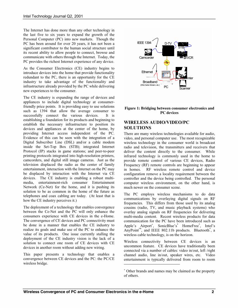
This paper presents a technology that enables a convergence between CE devices and the PC: the PC/CE wireless bridge.
Camcorder
D-TVSTB
D-VCR
Broadband(DSL/Cable Modem, etc.)
PC
Printer
Scanner
IEEE 1394
Ethernet
Figure 1: Bridging between consumer electronics and PC devices
WIRELESS AUDIO/VIDEO/PC SOLUTIONS There are many wireless technologies available for audio, video, and personal computer use. The most recognizable wireless technology in the consumer world is broadcast radio and television, the transmitters and receivers that deliver the content directly to the consumer. While infrared technology is commonly used in the home to provide remote control of various CE devices, Radio Frequency (RF) remote controls are beginning to appear in homes. RF wireless remote control and device configuration remove a locality requirement between the controller and the device being controlled. The personal computer wireless environment, on the other hand, is much newer on the consumer scene.
The PC employs wireless mechanisms to do data communications by overlaying digital signals on RF frequencies. This differs from those used by its analog cousins (radio, TV, and music playback systems) who overlay analog signals on RF frequencies for delivering multi-media content. Recent wireless products for data communication for the PC have been introduced such as Apple’s Airport∗, SonicBlue’s* HomeFree*, Intel’s AnyPoint™, and IEEE 802.11b products. Bluetooth*, a wireless cable technology, is on the horizon.
Wireless connectivity between CE devices is an uncommon feature. CE devices have traditionally been connected via a number of cables: video in/out, left /right channel audio, line in/out, speaker wires, etc. Video entertainment is typically delivered from room to room ∗ Other brands and names may be claimed as the property of others.
Intel Technology Journal Q2, 2001
Wireless Convergence of PC and Consumer Electronics in the e-Home 3
via coax cable or not at all–challenging consumers to find a solution for delivering video and audio to the rooms in their homes.
No matter what the consumer does, command, control, and configuration of CE devices always end up back at the source device. The CE multi-media entertainment 1394 interconnects provide a peer-to-peer-based solution: the delivery of content, command, configuration, and control of any one device may be initiated by any other device.
Even with the advent of 1394, the problem of connecting devices between rooms remains. In particular, how can consumers establish a connection between devices in one room to devices in a separate room without installing additional (new) wires in the home? The CE industry has identified IEEE 1394b as the long-term wired solution. This solution requires that new wires be installed in the home and does nothing to address existing homes and their existing wiring infrastructure.
This has motivated the CE industry to investigate how to interconnect devices in different rooms using a wireless medium, spawning proprietary solutions that do not interoperate. So far, no one solution has penetrated a significant portion of the consumer market.
Moreover, the quantity of high-quality content and the extended capabilities available from the next generation of CE industry multi-media entertainment devices will only compound the existing problem of delivering multi-media entertainment content from device to device and room to room.
THE CLUSTER ENVIRONMENT The cluster of consumer multi-media entertainment devices is familiar to most consumers. It consists of a group of devices co-located and interconnected (e.g., the television, a VHS recorder, a Set-Top Box [STB], a CD player, and a DVD player). There may be an AM/FM tuner in the cluster and a common amplifier or home theater system. These devices are cabled together in the entertainment center today using an assortment of wires such as traditional RCA-style interconnect cables and bare wire connections to thumb screw terminals and coax. The resulting cabling mess is very difficult to manage when removing or adding devices.
This problem has been compounded by AC-3 audio requiring more than a doubling of wires to speakers and additional connections to various devices like the DVD player, TV, and audio decoder. Many consumers require these to be professionally installed because of the complexity.
As Consumer Electronic (CE) devices advance and incorporate a 1394 interconnect interface, the consumer
will gradually replace existing CE devices with newer, more capable digital multi-media entertainment products. Eventually, all CE multi-media entertainment devices within a single location in the home will be cabled together by a daisy-chained 1394 cable connection. The television, STB, VHS recorder, and other devices may have two or more 1394 sockets that enable the daisy-chain feature. These devices will continue to interact with each other under the control of the consumer, similar to the current generation of CE devices.
Many rooms in a home may have similar CE multi-media clusters of devices–a subset or superset of what may be found in other rooms of the home.
The Personal Computer Many homes today have personal computers but in most cases, the computer does not interact with other consumer devices in the home. The PC may be used to create MP3 files for loading on portable players, but there is no simple or universal way to interconnect the PC with the CE devices in the home.
There are many homes with multiple PCs. The PCs in some of these homes have been connected together to form a home network. There is a variety of ways to provide connectivity for home networks. In addition to the wireless solutions listed previously, there are wired solutions such as HomePlug∗, Home-PNA∗, and Cat-5 Ethernet. Most CE devices do not support these home network solutions.
The PC, PC peripherals (printers, scanners, modems, storage devices, etc.), and Internet connectivity exist separately from any CE device clusters. In effect, the PC and CE devices exist as isolated clusters.
WIRELESS CONVERGENCE Assuming a general requirement that no new wires shall be incorporated into existing homes, creating the e-Home is quite a challenge. One solution that may satisfy the above requirement is wireless transmission of data and multi-media entertainment content for both the Personal Computer (PC) and the Consumer Electronic (CE) devices.
There are efforts being made in both the PC and the CE industry to interconnect their respective devices using a wireless medium. These have been independent efforts and interoperability between CE devices and the PC were not considered.
∗ Other brands and names may be claimed as the property of others.
Intel Technology Journal Q2, 2001
Wireless Convergence of PC and Consumer Electronics in the e-Home 4
Recently, there has been an effort to develop a wireless solution to interconnect PC and CE multi-media entertainment clusters thereby enabling interoperation and interaction between the two worlds. This wireless solution would be the missing link that enables the PC to become a logical multi-media entertainment 1394 device. It would allow it to locate and identify all multi-media entertainment 1394 devices without being co-located with the entertainment cluster and also provide a consistent interface to the Internet for those devices.
Bridging Bridging is a term describing a mechanism that connects one method of performing functions to a different method of performing the same or similar functions. The function is not able to determine which mechanism was used to invoke the function.
For example, the method used to transport data between PCs over Ethernet is much different than the method used between CE devices over 1394. A bridge between 1394 and Ethernet creates an environment where the PC cannot determine if the data were originally sourced from Ethernet or 1394.
There are three ways to view bridging a wired 1394
Ce-Net to a wireless transport:
• Wired-to-Wireless
• Wired-to-Wired via a wireless transport
• Wired-to-Wired via a wireless transport with support for wireless device class types
IEEE 802.11 is a wireless standard designed to transport Ethernet datagrams used by computer networks. IEEE 802.11 can be used as a common wireless transport for interconnecting PC and CE devices to achieve convergence.
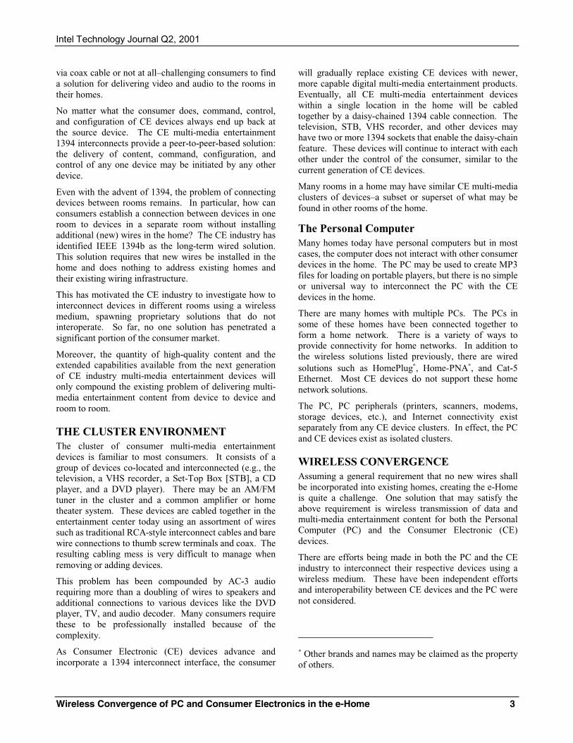
There is considerable value in creating a 1394 to 802.11 bridge that enables interoperability between CE 1394 devices and PCs. The PC can add significant value as a digital content creation tool and as a tool for universal command, control, and configuration. The PC may also be able to provide Internet and World Wide Web content to the CE multi-media entertainment 1394 cluster. Figure 2 shows such an implementation.
PC
IEEE 1394
IEEE 802.11
!
!
CE DeviceMulti-Media1394 Cluster
Figure 2: CE device multi-media entertainment (1394) wireless bridge to the PC
This style of bridge does little to resolve the issue of interconnecting clusters of CE multi-media entertainment 1394 devices. It also ignores the fact that connecting the two worlds involves more than just the physical connection. The content and control methods must be interoperable.
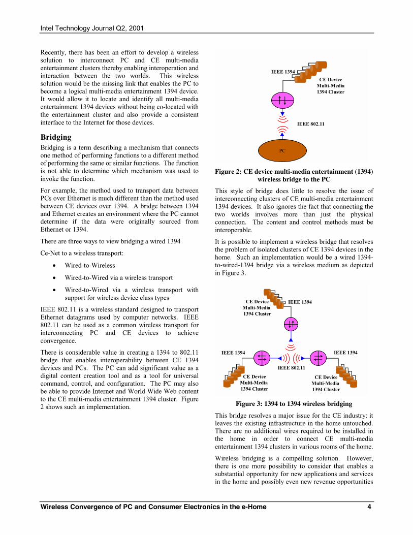
It is possible to implement a wireless bridge that resolves the problem of isolated clusters of CE 1394 devices in the home. Such an implementation would be a wired 1394-to-wired-1394 bridge via a wireless medium as depicted in Figure 3.
IEEE 1394
IEEE 802.11
!
!
IEEE 1394
!
IEEE 1394CE DeviceMulti-Media 1394 Cluster
CE DeviceMulti-Media 1394 Cluster
CE DeviceMulti-Media 1394 Cluster
Figure 3: 1394 to 1394 wireless bridging
This bridge resolves a major issue for the CE industry: it leaves the existing infrastructure in the home untouched. There are no additional wires required to be installed in the home in order to connect CE multi-media entertainment 1394 clusters in various rooms of the home.
Wireless bridging is a compelling solution. However, there is one more possibility to consider that enables a substantial opportunity for new applications and services in the home and possibly even new revenue opportunities
Intel Technology Journal Q2, 2001
Wireless Convergence of PC and Consumer Electronics in the e-Home 5
for those companies engaged in developing and delivering the product in the CE device and PC market.
IEEE 1394
IEEE 802.11
!
!
IEEE 1394
!
IEEE 1394CE DeviceMulti-Media1394Cluster
!
PC Cluster
CE DeviceMulti-Media1394Cluster
CE DeviceMulti-Media1394Cluster
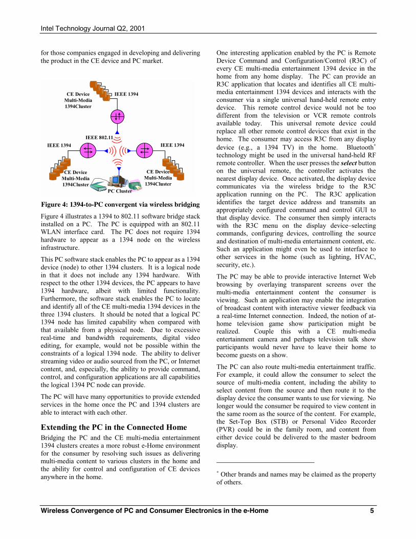
Figure 4: 1394-to-PC convergent via wireless bridging
Figure 4 illustrates a 1394 to 802.11 software bridge stack installed on a PC. The PC is equipped with an 802.11 WLAN interface card. The PC does not require 1394 hardware to appear as a 1394 node on the wireless infrastructure.
This PC software stack enables the PC to appear as a 1394 device (node) to other 1394 clusters. It is a logical node in that it does not include any 1394 hardware. With respect to the other 1394 devices, the PC appears to have 1394 hardware, albeit with limited functionality. Furthermore, the software stack enables the PC to locate and identify all of the CE multi-media 1394 devices in the three 1394 clusters. It should be noted that a logical PC 1394 node has limited capability when compared with that available from a physical node. Due to excessive real-time and bandwidth requirements, digital video editing, for example, would not be possible within the constraints of a logical 1394 node. The ability to deliver streaming video or audio sourced from the PC, or Internet content, and, especially, the ability to provide command, control, and configuration applications are all capabilities the logical 1394 PC node can provide.
The PC will have many opportunities to provide extended services in the home once the PC and 1394 clusters are able to interact with each other.
Extending the PC in the Connected Home Bridging the PC and the CE multi-media entertainment 1394 clusters creates a more robust e-Home environment for the consumer by resolving such issues as delivering multi-media content to various clusters in the home and the ability for control and configuration of CE devices anywhere in the home.
One interesting application enabled by the PC is Remote Device Command and Configuration/Control (R3C) of every CE multi-media entertainment 1394 device in the home from any home display. The PC can provide an R3C application that locates and identifies all CE multi-media entertainment 1394 devices and interacts with the consumer via a single universal hand-held remote entry device. This remote control device would not be too different from the television or VCR remote controls available today. This universal remote device could replace all other remote control devices that exist in the home. The consumer may access R3C from any display device (e.g., a 1394 TV) in the home. Bluetooth∗ technology might be used in the universal hand-held RF remote controller. When the user presses the select button on the universal remote, the controller activates the nearest display device. Once activated, the display device communicates via the wireless bridge to the R3C application running on the PC. The R3C application identifies the target device address and transmits an appropriately configured command and control GUI to that display device. The consumer then simply interacts with the R3C menu on the display device–selecting commands, configuring devices, controlling the source and destination of multi-media entertainment content, etc. Such an application might even be used to interface to other services in the home (such as lighting, HVAC, security, etc.).
The PC may be able to provide interactive Internet Web browsing by overlaying transparent screens over the multi-media entertainment content the consumer is viewing. Such an application may enable the integration of broadcast content with interactive viewer feedback via a real-time Internet connection. Indeed, the notion of at-home television game show participation might be realized. Couple this with a CE multi-media entertainment camera and perhaps television talk show participants would never have to leave their home to become guests on a show.
The PC can also route multi-media entertainment traffic. For example, it could allow the consumer to select the source of multi-media content, including the ability to select content from the source and then route it to the display device the consumer wants to use for viewing. No longer would the consumer be required to view content in the same room as the source of the content. For example, the Set-Top Box (STB) or Personal Video Recorder (PVR) could be in the family room, and content from either device could be delivered to the master bedroom display.
∗ Other brands and names may be claimed as the property of others.
Intel Technology Journal Q2, 2001
Wireless Convergence of PC and Consumer Electronics in the e-Home 6
In a home security model, the CE 1394 devices could be controlled by a PC software application to simulate activity in the home, thereby providing the illusion of occupancy to an unoccupied home.
Videophones could become common with the PC delivering streaming video to any display in the home, as CE multi-media 1394 cameras become part of an interactive display device.
Numerous applications will be enabled once wireless interoperability between PC and CE devices has been achieved.
CONSUMER ELECTRONICS/PC CONVERGENCE Full Consumer Electronics/Personal Computer CE/PC convergence is not a simple task. There are separate and unique requirements for the PC datagram network and the 1394 network, and both requirements must be met simultaneously on a single physical interconnect medium (two logical networks running over one physical network). Both networks will be required to adopt new methods and mechanisms to eliminate barriers to bridging with the other device class.
Current PC wireless datagram networks have significantly less bandwidth than a wired 1394 network. This fact results in a wireless 1394 implementation that is very limited in the number of high-definition video (24Mbps) streams it can support. In fact, one video stream may be all that can be supported. A wireless 1394 network may be required to relax the quality of the video it delivers over the wireless infrastructure. Instead of a single 24Mbps stream, perhaps two or three 5Mbps streams could be realized. The quality of such streams would still be far superior to the quality consumers have grown accustomed to today via their television antenna or cable TV connection.
Once isochronous video and audio is started, they cannot be interrupted or delayed without loss of content. For example, if a movie was divided into a finite number of smaller portions of video, each portion must be delivered in order and in a specific time frame relative to the previous one in order for the movie to be viewed in its original form. If the individual segments were received out of order or if one segment were delayed, the movie would be impossible to view. It is for this reason Quality of Service (QoS), or a guaranteed delivery in time and order, must be provided for the wireless transport of video and audio.
A wireless PC datagram transport that must support isochronous streams for multi-media entertainment content must have a QoS much greater than that for use in a datagram network.
Both the PC and CE industries will be required to make some protocol adjustments in their respective network implementations to achieve a common converged wireless network.
Current Industry Efforts There have been attempts in both the private CE industry community and in public standards’ bodies to establish a wireless transport medium for CE multi-media devices. All private CE industry implementations have been too costly to implement, and they have been proprietary and non-interoperable with other CE industry vendor implementations.
Today, there are three prominent standards-based efforts: ETSI/BRAN HiperLAN/2, MMAC in Japan/Asia, and the 1394 Trade Association. Each is engaged in addressing issues associated with implementing 1394 over a wireless transport. However, only the 1394 Trade Association is addressing a wireless bridge solution between CE devices and an existing PC industry wireless Local Area Network (LAN).
1394 Trade Association Recently, the 1394 Trade Association established a Wireless Working Group (WWG). Its charter is to survey industry needs and undertake projects that facilitate interconnection between IEEE 1394 (wired) domains and wireless domains for electronic equipment (e.g., A/V and PCs).
These domains may differ significantly at the lower-level protocol layers. Therefore, bridges will be essential for interconnection, and they will have to conceal differences that do not affect higher-level interoperability.
The WWG charter also requires it to select projects that
• are suitable for electronic equipment
• and consider harmonization with related efforts.
An architectural specification of a common implementation model for “bridge-aware” devices is a key project to be undertaken by the WWG. Such a model increases the likelihood that products will be interoperable across different domains.
The WWG is engaged in the creation of a Common Architecture Layer (CAL) specification that enables the creation of a Protocol Abstraction Layer (PAL) specification and its associated Protocol Interface Layer (PIL). The PAL and PIL define a standard method for implementing 1394 over 802.11. The CAL establishes a specific set of 1394 requirements that must be met in the PAL and PIL.
Intel Technology Journal Q2, 2001
Wireless Convergence of PC and Consumer Electronics in the e-Home 7
The objective of these projects is to develop an implementation guideline specification that covers methods to do the following:
a) Mimic IEEE 1394 infrastructure (transactions, isochrony, stream data, configuration ROM and CSR architecture) using the facilities of IEEE 802.11.
b) Implement IEEE P1394.1 bridge behaviors in the same domain. The methods are to be compatible with the simultaneous use of IEEE 802.11 by other protocols, e.g., Internet protocol.
The WWG PAL project will result in a standard specification OEMs may refer to in implementing a 1394 wireless bridge to a PC Ethernet 802.11a WLAN, thus enabling the PC to interoperate with 1394 CE devices.
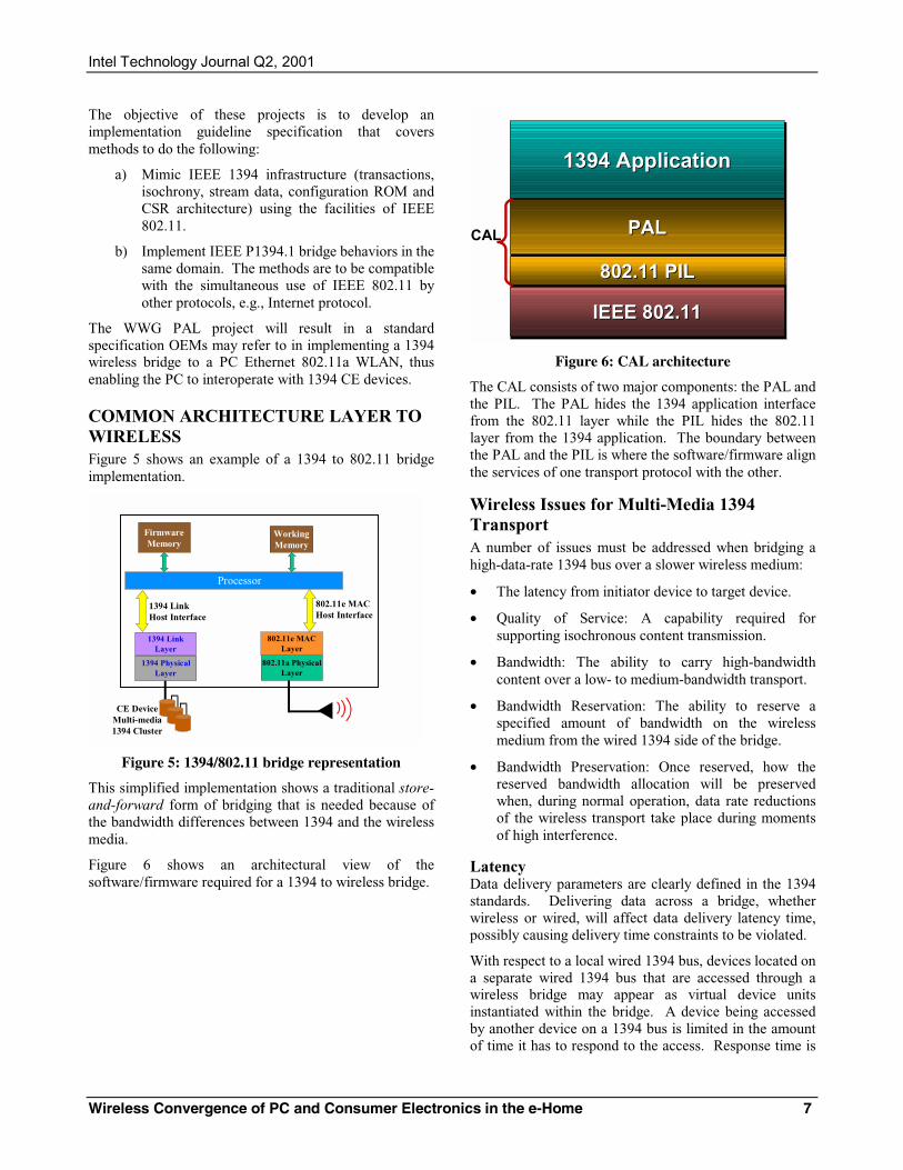
COMMON ARCHITECTURE LAYER TO WIRELESS Figure 5 shows an example of a 1394 to 802.11 bridge implementation.
802.11a PhysicalLayer
1394 PhysicalLayer
1394 LinkLayer
1394 LinkHost Interface
Processor
WorkingMemory
802.11e MACLayer
802.11e MAC Host Interface
FirmwareMemory
CE DeviceMulti-media1394 Cluster
!
Figure 5: 1394/802.11 bridge representation
This simplified implementation shows a traditional store-and-forward form of bridging that is needed because of the bandwidth differences between 1394 and the wireless media.
Figure 6 shows an architectural view of the software/firmware required for a 1394 to wireless bridge.
1394 Application1394 Application
IEEE 802.11IEEE 802.11
PALPAL
802.11 PIL802.11 PIL
CAL
Figure 6: CAL architecture
The CAL consists of two major components: the PAL and the PIL. The PAL hides the 1394 application interface from the 802.11 layer while the PIL hides the 802.11 layer from the 1394 application. The boundary between the PAL and the PIL is where the software/firmware align the services of one transport protocol with the other.
Wireless Issues for Multi-Media 1394 Transport A number of issues must be addressed when bridging a high-data-rate 1394 bus over a slower wireless medium:
• The latency from initiator device to target device.
• Quality of Service: A capability required for supporting isochronous content transmission.
• Bandwidth: The ability to carry high-bandwidth content over a low- to medium-bandwidth transport.
• Bandwidth Reservation: The ability to reserve a specified amount of bandwidth on the wireless medium from the wired 1394 side of the bridge.
• Bandwidth Preservation: Once reserved, how the reserved bandwidth allocation will be preserved when, during normal operation, data rate reductions of the wireless transport take place during moments of high interference.
Latency Data delivery parameters are clearly defined in the 1394 standards. Delivering data across a bridge, whether wireless or wired, will affect data delivery latency time, possibly causing delivery time constraints to be violated.
With respect to a local wired 1394 bus, devices located on a separate wired 1394 bus that are accessed through a wireless bridge may appear as virtual device units instantiated within the bridge. A device being accessed by another device on a 1394 bus is limited in the amount of time it has to respond to the access. Response time is

Intel Technology Journal Q2, 2001
Wireless Convergence of PC and Consumer Electronics in the e-Home 8
significantly delayed when access to a device must occur through a bridge. Care must be taken not to violate the response time specified by the 1394 standard.
When a device on a wired local 1394 bus addresses a device through a bridge, such as an 802.11 bridge, the bridge must respond with “acknowledge pending.” This extends the response time allowed by the destination device.
Once a pending acknowledgement has been sent, the 1394 bridge transmits the data across the wireless medium to the actual target device.
All wireless bridges will receive the transaction. Only the wireless bridge with an ID that matches the target device will respond. The responding bridge forwards the data to the target device. The target device issues a true response. The true response is forwarded to the initiator through the bridge
Isochronous data do not require acknowledgement on receipt. Late or lost isochronous data are lost and are useless. Isochronous data are real time data that lose their value if not delivered at the scheduled time–they cannot be viewed or heard in the way intended.
Quality of Service (QoS) QoS is the mechanism that ensures data are delivered in a scheduled time frame.
QoS is associated with a specific regularly scheduled timing event such as a Cycle Start packet, which occurs approximately every 125 microseconds on a wired 1394 bus. Each time the event occurs, initiators of time-critical data may resynchronize. Once an initiator is able to lock to a synchronous clock, it may reliably schedule the delivery of content and rely on its delivery.
Work is currently in progress in the IEEE 802.11 organization to develop a QoS standard that is adequate for the delivery of isochronous multi-media content.
Bandwidth Reservation Though it is possible to transport one high-definition audio/video stream of about 24Mbps across an 802.11a/e transport, the bandwidth available over the wireless medium is significantly smaller than that available in a wired 1394 environment.
A 1394/802.11 bridge must be able to provide a 1394 device the ability to reserve a specific amount of bandwidth (e.g., 24Mbps). Mechanisms available in Ethernet protocol are not appropriate due to their existence within a higher layer of the software stack, and they are not available to the 1394 bridge. Reservation mechanisms are required at the Media Access Control (MAC) layer. This issue is being addressed within the
IEEE 802.11 working groups and the WWG of the 1394 Trade Association.
Bandwidth Preservation A unique property of WLAN bandwidth management is its ability to scale back bit rate when the channel degrades due to interference or other problems.
Scaling down bit rate poses a problem for 1394 when a specific amount of bandwidth has previously been allocated. For example, a reduction of bit rate from 30Mbps to 15Mbps would pose a problem if a 1394 bridge port may have reserved 24Mbps for the transmission of an HDTV stream. This issue has not yet been taken up in the IEEE 802.11 working groups or the 1394 Trade Association WWG.
One possible solution would be to constrain the bandwidth available to the 1394 bridge to an amount equal to the lowest guaranteed bandwidth of the wireless media transport. Constraining the available bandwidth in such a manner eliminates the ability to transmit high-definition video. Another approach would be to transmit lower bandwidth MPEG2 standard definition streams. The quality of these video streams is significantly higher than the consumer currently experiences via cable or antenna. This may be an acceptable compromise until an advanced technique such as turbo-coding1 is deployed to increase wireless bandwidth.
Protocol Abstraction Layer (PAL) The PAL, as a software/firmware layer, provides an interface between the low-level mechanisms of a 1394 layer and the front end of the PIL. The PAL hides the details of the 1394 layer and presents a common, standard set of services to the PIL. Using these services, the PAL layer is able to mimic the high-level behavior of 1394 when presenting and accepting data to and from the PIL, while also conforming to the high-level behaviors of the wireless transport when delivering these data to their destination.
There are certain ground rules that must be adhered to when developing a PAL. A PAL must support 1394 transaction layer functions, isochronous data traffic and streaming data, and it must coexist with other uses of the underlying wireless transport (e.g., IP).
In summary, the PAL must behave like 1394, concealing the differences between the 1394 and 802.11 physical and link (MAC) layers.
1 Turbo-coding is a method in which two channels of the wireless medium are used to transmit data, thus, effectively nearly doubling the available bandwidth. In the case of 802.11a, a real bandwidth of 30Mbps might be raised to approximately 60Mbps. Exact doubling is not achieved due to the additional overhead of managing the medium.
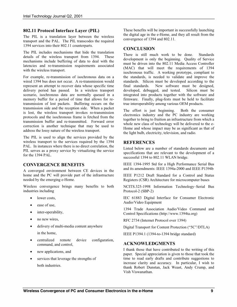
Intel Technology Journal Q2, 2001
Wireless Convergence of PC and Consumer Electronics in the e-Home 9
802.11 Protocol Interface Layer (PIL) The PIL is a translation layer between the wireless transport and the PAL. The PIL transcodes the required 1394 services into their 802.11 counterparts.
The PIL includes mechanisms that hide the translation details of the wireless transport from 1394. These mechanisms include buffering of data to deal with the latencies and re-transmission requirements associated with the wireless transport.
For example, re-transmission of isochronous data on a wired 1394 bus does not occur. A re-transmission would represent an attempt to recover data whose specific time delivery period has passed. In a wireless transport scenario, isochronous data are normally queued in a memory buffer for a period of time that allows for re-transmission of lost packets. Buffering occurs on the transmission side and the reception side. When a packet is lost, the wireless transport invokes re-transmission protocols and the isochronous frame is fetched from the transmission buffer and re-transmitted. Forward error correction is another technique that may be used to address the lossy nature of the wireless transport.
The PIL is used to align the services provided by the wireless transport to the services required by the 1394 PAL. In instances where there is no direct correlation, the PIL serves as a proxy service by virtualizing the service for the 1394 PAL.
CONVERGENCE BENEFITS A converged environment between CE devices in the home and the PC will provide part of the infrastructure needed by the emerging e-Home.
Wireless convergence brings many benefits to both industries including
• lower costs,
• ease of use,
• inter-operability,
• no new wires,
• delivery of multi-media content anywhere
in the home,
• centralized remote device configuration, command, and control,
• new applications, and
• services that leverage the strengths of
both industries.
These benefits will be important in successfully launching the digital age in the e-Home, and they all result from the convergence of 1394 and 802.11.
CONCLUSION There is still much work to be done. Standards development is only the beginning. Quality of Service must be driven into the 802.11 Media Access Controller (MAC) that will meet the requirements of 1394 isochronous traffic. A working prototype, compliant to the standards, is needed to validate and improve the standards. Silicon must be developed according to the final standards. New software must be designed, developed, debugged, and tested. Silicon must be integrated into products together with the software and firmware. Finally, plug-fests must be held to facilitate true interoperability among various OEM products.
The effort is just beginning. Both the consumer electronics industry and the PC industry are working together to bring to fruition an infrastructure from which a whole new class of technology will be delivered to the e-Home and whose impact may be as significant as that of the light bulb, electricity, television, and radio.
REFERENCES Listed below are a number of standards documents and specifications that are relevant to the development of a successful 1394 to 802.11 WLAN bridge.
IEEE 1394-1995 Std for a High Performance Serial Bus and its amendments: IEEE 1394a-2000 and IEEE P1394b
IEEE P1212 Draft Standard for a Control and Status Registers (CSR) Architecture for microcomputer buses
NCITS.325-1998 Information Technology–Serial Bus Protocol-2 (SBP-2)
IEC 61883 Digital Interface for Consumer Electronic Audio/Video Equipment
1394 Trade Association Audio/Video Command and Control Specifications (http://www.1394ta.org)
RFC 2734 (Internet Protocol over 1394)
Digital Transport for Content Protection (“5C”/DTLA)
IEEE P1394.1 (1394-to-1394 bridge standard)
ACKNOWLEDGMENTS I thank those that have contributed to the writing of this paper. Special appreciation is given to those that took the time to read early drafts and contribute suggestions to increase clarity and accuracy. In particular, I wish to thank Robert Dunstan, Jack Weast, Andy Crump, and Vish Viswanathan.
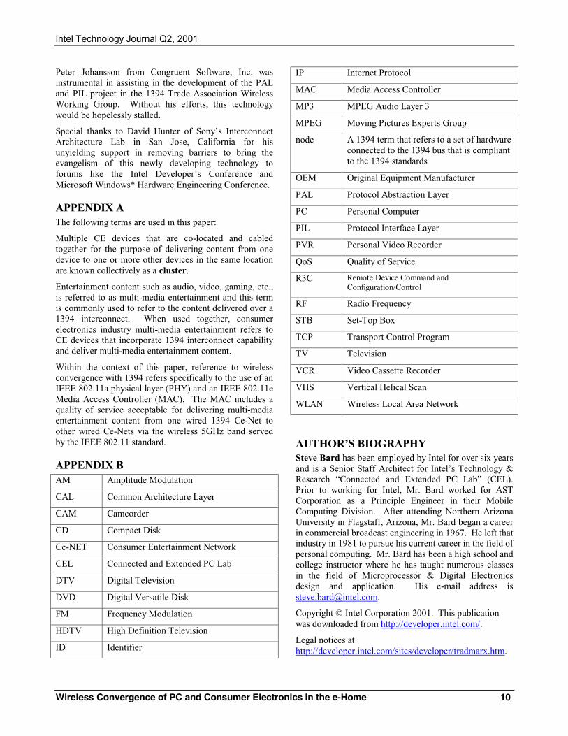
Intel Technology Journal Q2, 2001
Wireless Convergence of PC and Consumer Electronics in the e-Home 10
Peter Johansson from Congruent Software, Inc. was instrumental in assisting in the development of the PAL and PIL project in the 1394 Trade Association Wireless Working Group. Without his efforts, this technology would be hopelessly stalled.
Special thanks to David Hunter of Sony’s Interconnect Architecture Lab in San Jose, California for his unyielding support in removing barriers to bring the evangelism of this newly developing technology to forums like the Intel Developer’s Conference and Microsoft Windows* Hardware Engineering Conference.
APPENDIX A The following terms are used in this paper:
Multiple CE devices that are co-located and cabled together for the purpose of delivering content from one device to one or more other devices in the same location are known collectively as a cluster.
Entertainment content such as audio, video, gaming, etc., is referred to as multi-media entertainment and this term is commonly used to refer to the content delivered over a 1394 interconnect. When used together, consumer electronics industry multi-media entertainment refers to CE devices that incorporate 1394 interconnect capability and deliver multi-media entertainment content.
Within the context of this paper, reference to wireless convergence with 1394 refers specifically to the use of an IEEE 802.11a physical layer (PHY) and an IEEE 802.11e Media Access Controller (MAC). The MAC includes a quality of service acceptable for delivering multi-media entertainment content from one wired 1394 Ce-Net to other wired Ce-Nets via the wireless 5GHz band served by the IEEE 802.11 standard.
APPENDIX B AM Amplitude Modulation
CAL Common Architecture Layer
CAM Camcorder
CD Compact Disk
Ce-NET Consumer Entertainment Network
CEL Connected and Extended PC Lab
DTV Digital Television
DVD Digital Versatile Disk
FM Frequency Modulation
HDTV High Definition Television
ID Identifier
IP Internet Protocol
MAC Media Access Controller
MP3 MPEG Audio Layer 3
MPEG Moving Pictures Experts Group
node A 1394 term that refers to a set of hardware connected to the 1394 bus that is compliant to the 1394 standards
OEM Original Equipment Manufacturer
PAL Protocol Abstraction Layer
PC Personal Computer
PIL Protocol Interface Layer
PVR Personal Video Recorder
QoS Quality of Service
R3C Remote Device Command and Configuration/Control
RF Radio Frequency
STB Set-Top Box
TCP Transport Control Program
TV Television
VCR Video Cassette Recorder
VHS Vertical Helical Scan
WLAN Wireless Local Area Network
AUTHOR’S BIOGRAPHY Steve Bard has been employed by Intel for over six years and is a Senior Staff Architect for Intel’s Technology & Research “Connected and Extended PC Lab” (CEL). Prior to working for Intel, Mr. Bard worked for AST Corporation as a Principle Engineer in their Mobile Computing Division. After attending Northern Arizona University in Flagstaff, Arizona, Mr. Bard began a career in commercial broadcast engineering in 1967. He left that industry in 1981 to pursue his current career in the field of personal computing. Mr. Bard has been a high school and college instructor where he has taught numerous classes in the field of Microprocessor & Digital Electronics design and application. His e-mail address is [email protected].
Copyright © Intel Corporation 2001. This publication was downloaded from http://developer.intel.com/.
Legal notices at http://developer.intel.com/sites/developer/tradmarx.htm.
Intel Technology Journal Q2, 2001
Wireless Convergence of PC and Consumer Electronics in the e-Home 11
Extending the PC in the Home 1
Extending the PC in the Home
Craig Merrick, Solutions Enabling Group, Intel Corp.Robert Dunstan, Connected and Extended PC Lab, Intel Corp.
Michael Jeronimo, Connected and Extended PC Lab, Intel Corp.
Index words: e-Home, extended PC, devices, home network, Home Services Framework
ABSTRACTMany technologies introduced into the home have becomea part of everyday life. Today, many factors, such as theavailability of broadband access, the growth of homenetworks, and the popularity of devices such as PersonalDigital Assistants (PDAs) and cell phones are combiningto reshape the home use of electronics. As all the devicesin the home become fully connected, we move towards thenext step in its evolution, the e-Home. The e-Homepresents significant new benefits to consumers andbusiness opportunities for home technology providers.One such opportunity is the delivery of network-basedservices and applications to the consumer.
However, there are challenging technological barriers toovercome before the e-Home can meet its full potential.In today’s home, there are various types ofinterconnections between computing, control,communication, and entertainment devices. Theseincompatible technologies and communications protocolsresult in such devices existing on disparate islands ofconnectivity. Complicating this issue is the explosion inthe number of mobile, wireless devices that should be fullparticipants in the virtual home network. Much workneeds to be done to organize and bridge thesecommunications gaps into a single, virtual home network.
The new extended PC will be a coordinator of activity inthe e-Home, bridging the various home networks andproviding the central computing and communicationengine for new kinds of applications that take advantageof the connected nature of home devices. This paperpresents an overall vision and architectural framework forthe connected home of the future. It describes how theextended PC plays a vital role in this evolution, identifiesthe necessary infrastructure to move to a single virtualnetwork, and recommends a standard, open framework toenable delivery of managed services into the home.
INTRODUCTIONIn the early part of the twentieth century, novel servicessuch as electricity and telephones began to find their wayinto homes. Early adopters got a few electric lights, someoutlets, and a phone with a crank hung on a wall. By the1920s, recorded sounds made their way into the home onEdison wax cylinders, and moving pictures were widelyavailable in theaters. Radio broadcasts, the first wholesaledelivery of media into the home, also began in the 1920s.Radio networks featuring live music, soap operas, andradio theater sprang up in the 1930s, and by the late1940s, television brought the movie theater into the home.Both radio and television created opportunities for newand different forms of entertainment, and over thedecades, these technologies expanded their presence in thehome.
Fast forward to the beginning of the twenty-first century.Electricity is now delivered ubiquitously throughout thehome. The telephone is present in every room, enabled bypre-wired jacks and wireless phones. The CD hasreplaced the Edison recording cylinder, and radios arenow utilitarian devices that have long since lost theirvenerated place as the center of home entertainment, atleast in Western society. The television has become thecenter of family entertainment, and computers haveentered the home as multi-purpose tools used for e-mail,family finance, gaming, and Web browsing. There arealso many portable devices scattered throughout the home,such as wireless phones, hand-held gaming systems,Personal Digital Assistants (PDAs), cell phones, MP3players, CD players, and various remote controls.
Despite the continuous advancements in technology, mostdevices in the home today are organized into isolatedislands of connectivity. Because of this communicationgap, significant potential value to the consumer liesdormant. By extending the PC’s reach in the home andbridging this connectivity gap, the extended PC willbecome a catalyst, moving home technology to the next
Intel Technology Journal Q2, 2001
Extending the PC in the Home 2
level, reaching another milestone in the evolution of hometechnology.
Technology TrendsThe PC industry has enjoyed phenomenal growth over thepast decade. This growth has been fueled by a market thatprovides the industry with a single design target and largeeconomies of scale. The Internet has also been a keyfactor in this growth and it is starting to reach out tonon-traditional computing environments. Going forward,there is a potential for fragmentation in the marketplace.Vendors are starting to offer Internet-based productswithout a common technological foundation, oftenreinventing the wheel. In addition, vendors are faced withmany competing e-Home visions. The presence ofmultiple platforms and visions for the home threatens tosplinter the consumer market and slow growth byconfusing consumers with too many options, andfrustrating them with interoperability problems.
Devices and services should provide the customer witheasy access to information. However, if technologiesdon’t interoperate seamlessly across multiple platforms,adoption will be slowed. For example, if someone buys anew car with an MP3 stereo and the wireless connectionto his home music source uses a different type of radio oraccess protocol, he will be unable to conveniently transfermusic from the home library to the car. Similarly,streaming a movie from the PC to the television shouldnot be hindered by incompatible home Local AreaNetwork/Consumer Electronics (LAN/CE) clusterconnectivity. Without common methods to facilitate thesetypes of interactions, the incompatible mix of technologieswill slow consumer acceptance of new devices andservices.
According to Gartner Dataquest, there will be a 50 percentincrease in the number of corporate teleworkers in Europebetween 2001 and 2005, from about 12 million to morethan 18 million [1]. Many of these workers will usemultiple devices to access data in many different ways. Ifthese devices are easy to use and interoperate, the marketwill continue to grow at a rapid rate. Gartner alsoestimates that broadband access devices such as cable andDSL modems in Europe will increase from 2.4 percent ofthe remote access market in 1999, to more than 30 percentby 2005 [1]. Further growth will require a supportinginfrastructure of devices, applications, and services.Europe is just one market of many that is expected togrow dramatically over the next five years.
Interoperability StrategyAlthough many new devices and usage scenarios willemerge for the home, there needs to be significant industryalignment so that all consumer devices can be “well
behaved” and work together seamlessly. This will providethe basis for the convenience and ease of use consumersexpect. To address this problem, there is a need to extendthe value and flexibility of the PC architecture, and tointroduce a common infrastructure into the home. Thiswill enable the industry to deliver new devices, services,and applications that are interoperable and that utilizehome connectivity, infrastructure, and the extended PC toprovide a compelling new experience for the user.
The extended PC can maximize development by enablingvendors to more easily create interoperable products withshortened time-to-market. Interoperability will providethe convenience consumers require. Consumers should beable to easily integrate the devices into a seamlessenvironment that provides cost-effective access to dataand applications across devices and technologies frommany different companies. Interoperability will in turnpull consumers to devices they may not have consideredbefore.
Architectural DirectionsOpen architectures are generally well accepted in thecomputer industry and allow everyone to participate in agrowing marketplace, leading to more innovation andvalue for consumers.
An open architecture for the home should defineinteroperable building blocks for silicon, platforms, andsoftware infrastructure. It should also allow vendors todifferentiate products and to create value with the lowesttime-to-market. The PC industry must expand beyond theboundaries of current technology to include buildingblocks and end-to-end solutions that allow digital devicesand products to benefit from the extended PC in thee-Home.
The architecture described in this paper shows howdevices can be connected together in a manner thatenables the extended PC to provide additional capabilitiesto enhance their value. It shows how to migrate towards aunified virtual home network by addressing the challengesof connecting the many categories of networked electronicdevices found in homes today, including audio/video,data, telephone, and home automation. To maximizebenefit from these devices, the architecture includes anetwork where all devices are discoverable, configurable,and controllable, regardless of their physical connection.
EXISTING e-HOME COMPONENTSBefore mapping the path to the future e-Home, we firstdescribe existing components in the home, issues witheach, and areas for future development.
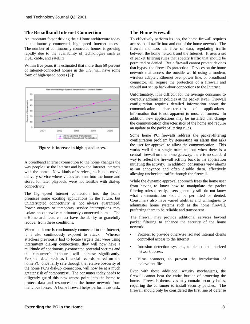
Intel Technology Journal Q2, 2001
Extending the PC in the Home 3
The Broadband Internet ConnectionAn important factor driving the e-Home architecture todayis continuously connected, high-speed Internet access.The number of continuously connected homes is growingrapidly due to the availability of technologies such asDSL, cable, and satellite.
Within five years it is estimated that more than 50 percentof Internet-connected homes in the U.S. will have someform of high-speed access [2]:
Figure 1: Increase in high-speed access
A broadband Internet connection to the home changes theway people use the Internet and how the Internet interactswith the home. New kinds of services, such as a moviedelivery service where videos are sent into the home andstored for later playback, were not feasible with dial-upconnectivity.
The high-speed Internet connection into the homepromises some exciting applications in the future, butuninterrupted connectivity is not always guaranteed.Power outages or temporary service interruptions mayisolate an otherwise continuously connected home. Thee-Home architecture must have the ability to gracefullyrecover from these conditions.
When the home is continuously connected to the Internet,it is also continuously exposed to attack. Whereasattackers previously had to locate targets that were usingintermittent dial-up connections, they will now have amultitude of continuously-connected potential victims andthe consumer’s exposure will increase significantly.Personal data, such as financial records stored on thehome PC, once fairly safe through the relative obscurity ofthe home PC’s dial-up connection, will now be at a muchgreater risk of compromise. The consumer today needs todiligently guard this new access point into the home toprotect data and resources on the home network frommalicious forces. A home firewall helps perform this task.
The Home FirewallTo effectively perform its job, the home firewall requiresaccess to all traffic into and out of the home network. Thefirewall monitors the flow of data, regulating trafficbetween the home network and the Internet. It uses a setof packet filtering rules that specify traffic that should bepermitted or denied. But a firewall cannot protect devicesthat bypass the firewall’s protection. Devices on the homenetwork that access the outside world using a modem,wireless adapter, Ethernet over power line, or broadbandconnector, all require the protection of a firewall andshould not set up back-door connections to the Internet.
Unfortunately, it is difficult for the average consumer tocorrectly administer policies at the packet level. Firewallconfiguration requires detailed information about thecommunication characteristics of applications–information that is not apparent to most consumers. Inaddition, new applications may be installed that changethe communication characteristics of the home and requirean update to the packet-filtering rules.
Some home PC firewalls address the packet-filteringconfiguration problem by generating an alarm that asksthe user for approval to allow the communication. Thisworks well for a single machine, but when there is acentral firewall on the home gateway, there is no standardway to reflect the firewall activity back to the applicationinitiating the activity. In addition, consumers view alarmsas an annoyance and often disable them, effectivelyallowing unchecked traffic through the firewall.
While the dynamic approval approach frees the home userfrom having to know how to manipulate the packetfiltering rules directly, users generally still do not knowwhat communication should be permitted or denied.Consumers also have varied abilities and willingness toadminister home systems such as the home firewall,preferring them to be reliable and transparent.
The firewall may provide additional services beyondpacket filtering to enhance the security of the homenetwork:
• Proxies, to provide otherwise isolated internal clientscontrolled access to the Internet.
• Intrusion detection systems, to detect unauthorizednetwork access.
• Virus scanners, to prevent the introduction ofmalevolent files.
Even with these additional security mechanisms, thefirewall cannot bear the entire burden of protecting thehome. Firewalls themselves may contain security holes,requiring the consumer to install security patches. Thefirewall should only be considered the first line of defense
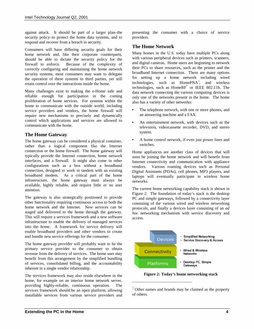
Intel Technology Journal Q2, 2001
Extending the PC in the Home 4
against attack. It should be part of a larger plan–thesecurity policy–to protect the home data systems, and torespond and recover from a breach in security.
Consumers will have differing security goals for theirhome network and, like their corporate counterparts,should be able to dictate the security policy for thefirewall to enforce. Because of the complexity ofcorrectly configuring and maintaining the home networksecurity systems, most consumers may want to delegatethe operation of these systems to third parties, yet stillretain control over the interactions inside the home.
Many challenges exist in making the e-Home safe andreliable enough for participation in the comingproliferation of home services. For systems within thehome to communicate with the outside world, includingservice providers and vendors, the home firewall willrequire new mechanisms to precisely and dynamicallycontrol which applications and services are allowed tocommunicate with the home.
The Home GatewayThe home gateway can be considered a physical container,rather than a logical component like the Internetconnection or the home firewall. The home gateway willtypically provide the Internet connection, home networkinterfaces, and a firewall. It might also come in otherconfigurations such as a box without a broadbandconnection, designed to work in tandem with an existingbroadband modem. As a critical part of the homeinfrastructure, the home gateway must always beavailable, highly reliable, and require little or no userattention.
The gateway is also strategically positioned to provideother functionality requiring continuous access to both thehome network and the Internet. New services can bestaged and delivered to the home through the gateway.This will require a services framework and a new softwareinfrastructure to enable the delivery of managed servicesinto the home. A framework for service delivery willenable broadband providers and other vendors to createand bundle new service offerings for the consumer.
The home gateway provider will probably want to be theprimary service provider to the consumer to obtainrevenue from the delivery of services. The home user maybenefit from this arrangement by the simplified bundlingof services, consolidated billing, and the accountabilityinherent in a single vendor relationship.
The services framework may also reside elsewhere in thehome, for example on an interior home network server,providing highly-reliable, continuous operation. Theservices framework should be an open platform, allowinginstallable services from various service providers and
presenting the consumer with a choice of serviceproviders.
The Home NetworkMany homes in the U.S. today have multiple PCs alongwith various peripheral devices such as printers, scanners,and digital cameras. Home users are beginning to networktheir PCs to share resources, such as the printer and thebroadband Internet connection. There are many optionsfor setting up a home network including wiredtechnologies, such as HomePNA∗ , and wirelesstechnologies, such as HomeRF* or IEEE 802.11b. Thedata network connecting the various computing devices isonly one of the networks present in the home. The homealso has a variety of other networks:
• The telephone network, with one or more phones, andan answering machine and a FAX.
• An entertainment network, with devices such as thetelevision, videocassette recorder, DVD, and stereosystem.
• A home control network, if even just power lines andswitches.
Home appliances are another class of devices that willsoon be joining the home network and will benefit fromInternet connectivity and communication with appliancevendors. Various roaming devices such as PersonalDigital Assistants (PDAs), cell phones, MP3 players, andlaptops will eventually participate in wireless homenetworks.
The current home networking capability stack is shown inFigure 2. The foundation of today’s stack is the desktopPC and simple gateways, followed by a connectivity layerconsisting of the various wired and wireless networkingprotocols, and finally a devices layer consisting of an adhoc networking mechanism with service discovery andaccess.
Figure 2: Today’s home networking stack
∗ Other names and brands may be claimed as the propertyof others.
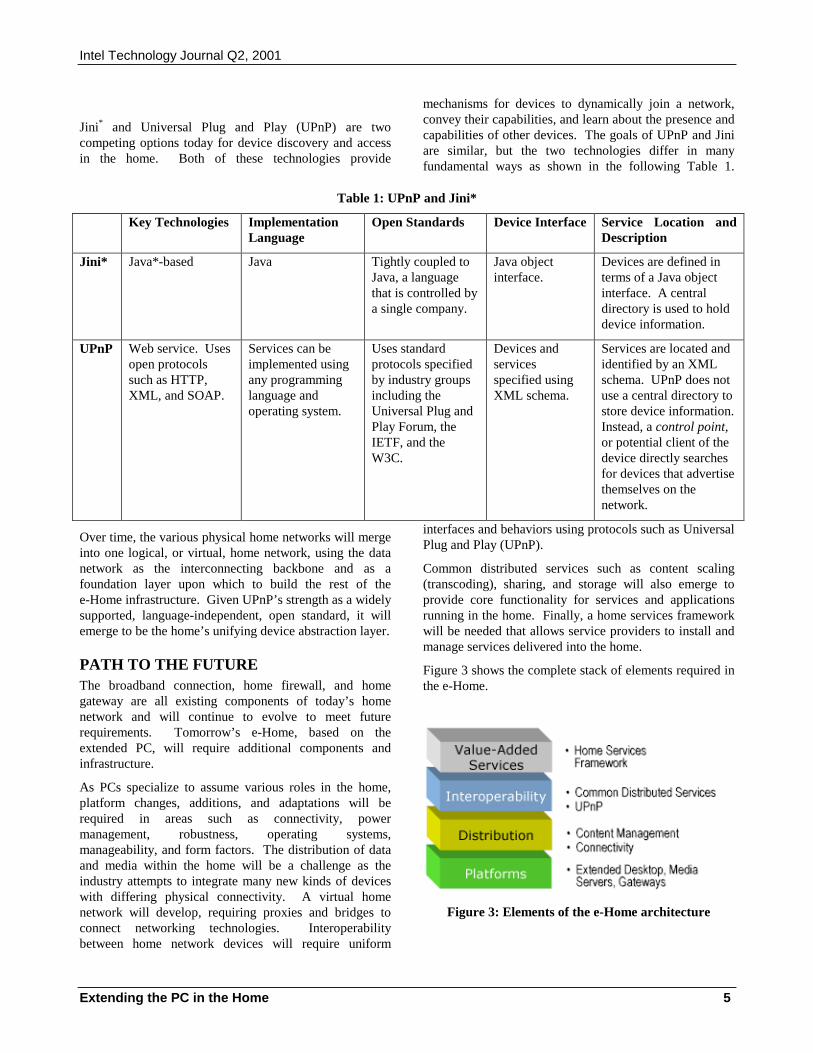
Intel Technology Journal Q2, 2001
Extending the PC in the Home 5
Jini* and Universal Plug and Play (UPnP) are twocompeting options today for device discovery and accessin the home. Both of these technologies provide
mechanisms for devices to dynamically join a network,convey their capabilities, and learn about the presence andcapabilities of other devices. The goals of UPnP and Jiniare similar, but the two technologies differ in manyfundamental ways as shown in the following Table 1.
Table 1: UPnP and Jini*
Key Technologies ImplementationLanguage
Open Standards Device Interface Service Location andDescription
Jini* Java*-based Java Tightly coupled toJava, a languagethat is controlled bya single company.
Java objectinterface.
Devices are defined interms of a Java objectinterface. A centraldirectory is used to holddevice information.
UPnP Web service. Usesopen protocolssuch as HTTP,XML, and SOAP.
Services can beimplemented usingany programminglanguage andoperating system.
Uses standardprotocols specifiedby industry groupsincluding theUniversal Plug andPlay Forum, theIETF, and theW3C.
Devices andservicesspecified usingXML schema.
Services are located andidentified by an XMLschema. UPnP does notuse a central directory tostore device information.Instead, a control point,or potential client of thedevice directly searchesfor devices that advertisethemselves on thenetwork.
Over time, the various physical home networks will mergeinto one logical, or virtual, home network, using the datanetwork as the interconnecting backbone and as afoundation layer upon which to build the rest of thee-Home infrastructure. Given UPnP’s strength as a widelysupported, language-independent, open standard, it willemerge to be the home’s unifying device abstraction layer.
PATH TO THE FUTUREThe broadband connection, home firewall, and homegateway are all existing components of today’s homenetwork and will continue to evolve to meet futurerequirements. Tomorrow’s e-Home, based on theextended PC, will require additional components andinfrastructure.
As PCs specialize to assume various roles in the home,platform changes, additions, and adaptations will berequired in areas such as connectivity, powermanagement, robustness, operating systems,manageability, and form factors. The distribution of dataand media within the home will be a challenge as theindustry attempts to integrate many new kinds of deviceswith differing physical connectivity. A virtual homenetwork will develop, requiring proxies and bridges toconnect networking technologies. Interoperabilitybetween home network devices will require uniform
interfaces and behaviors using protocols such as UniversalPlug and Play (UPnP).
Common distributed services such as content scaling(transcoding), sharing, and storage will also emerge toprovide core functionality for services and applicationsrunning in the home. Finally, a home services frameworkwill be needed that allows service providers to install andmanage services delivered into the home.
Figure 3 shows the complete stack of elements required inthe e-Home.
Figure 3: Elements of the e-Home architecture
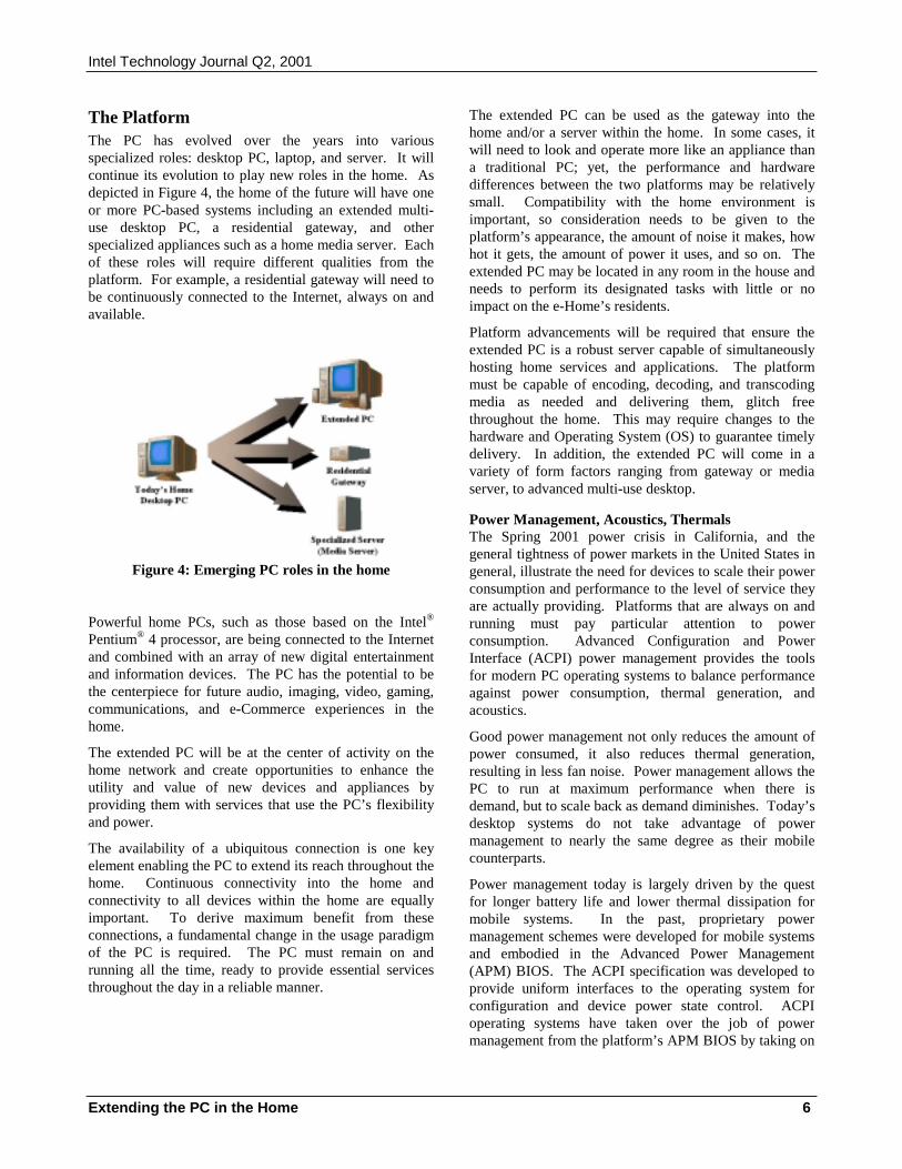
Intel Technology Journal Q2, 2001
Extending the PC in the Home 6
The PlatformThe PC has evolved over the years into variousspecialized roles: desktop PC, laptop, and server. It willcontinue its evolution to play new roles in the home. Asdepicted in Figure 4, the home of the future will have oneor more PC-based systems including an extended multi-use desktop PC, a residential gateway, and otherspecialized appliances such as a home media server. Eachof these roles will require different qualities from theplatform. For example, a residential gateway will need tobe continuously connected to the Internet, always on andavailable.
Figure 4: Emerging PC roles in the home
Powerful home PCs, such as those based on the Intel®
Pentium® 4 processor, are being connected to the Internetand combined with an array of new digital entertainmentand information devices. The PC has the potential to bethe centerpiece for future audio, imaging, video, gaming,communications, and e-Commerce experiences in thehome.
The extended PC will be at the center of activity on thehome network and create opportunities to enhance theutility and value of new devices and appliances byproviding them with services that use the PC’s flexibilityand power.
The availability of a ubiquitous connection is one keyelement enabling the PC to extend its reach throughout thehome. Continuous connectivity into the home andconnectivity to all devices within the home are equallyimportant. To derive maximum benefit from theseconnections, a fundamental change in the usage paradigmof the PC is required. The PC must remain on andrunning all the time, ready to provide essential servicesthroughout the day in a reliable manner.
The extended PC can be used as the gateway into thehome and/or a server within the home. In some cases, itwill need to look and operate more like an appliance thana traditional PC; yet, the performance and hardwaredifferences between the two platforms may be relativelysmall. Compatibility with the home environment isimportant, so consideration needs to be given to theplatform’s appearance, the amount of noise it makes, howhot it gets, the amount of power it uses, and so on. Theextended PC may be located in any room in the house andneeds to perform its designated tasks with little or noimpact on the e-Home’s residents.
Platform advancements will be required that ensure theextended PC is a robust server capable of simultaneouslyhosting home services and applications. The platformmust be capable of encoding, decoding, and transcodingmedia as needed and delivering them, glitch freethroughout the home. This may require changes to thehardware and Operating System (OS) to guarantee timelydelivery. In addition, the extended PC will come in avariety of form factors ranging from gateway or mediaserver, to advanced multi-use desktop.
Power Management, Acoustics, ThermalsThe Spring 2001 power crisis in California, and thegeneral tightness of power markets in the United States ingeneral, illustrate the need for devices to scale their powerconsumption and performance to the level of service theyare actually providing. Platforms that are always on andrunning must pay particular attention to powerconsumption. Advanced Configuration and PowerInterface (ACPI) power management provides the toolsfor modern PC operating systems to balance performanceagainst power consumption, thermal generation, andacoustics.
Good power management not only reduces the amount ofpower consumed, it also reduces thermal generation,resulting in less fan noise. Power management allows thePC to run at maximum performance when there isdemand, but to scale back as demand diminishes. Today’sdesktop systems do not take advantage of powermanagement to nearly the same degree as their mobilecounterparts.
Power management today is largely driven by the questfor longer battery life and lower thermal dissipation formobile systems. In the past, proprietary powermanagement schemes were developed for mobile systemsand embodied in the Advanced Power Management(APM) BIOS. The ACPI specification was developed toprovide uniform interfaces to the operating system forconfiguration and device power state control. ACPIoperating systems have taken over the job of powermanagement from the platform’s APM BIOS by taking on
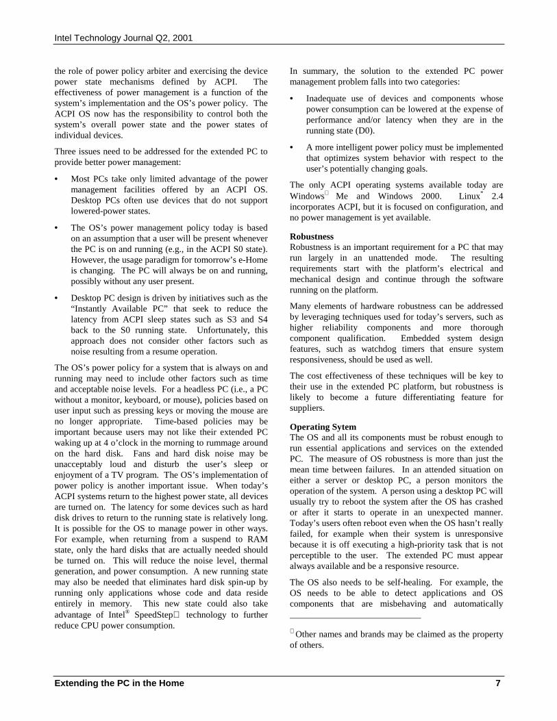
Intel Technology Journal Q2, 2001
Extending the PC in the Home 7
the role of power policy arbiter and exercising the devicepower state mechanisms defined by ACPI. Theeffectiveness of power management is a function of thesystem’s implementation and the OS’s power policy. TheACPI OS now has the responsibility to control both thesystem’s overall power state and the power states ofindividual devices.
Three issues need to be addressed for the extended PC toprovide better power management:
• Most PCs take only limited advantage of the powermanagement facilities offered by an ACPI OS.Desktop PCs often use devices that do not supportlowered-power states.
• The OS’s power management policy today is basedon an assumption that a user will be present wheneverthe PC is on and running (e.g., in the ACPI S0 state).However, the usage paradigm for tomorrow’s e-Homeis changing. The PC will always be on and running,possibly without any user present.
• Desktop PC design is driven by initiatives such as the“Instantly Available PC” that seek to reduce thelatency from ACPI sleep states such as S3 and S4back to the S0 running state. Unfortunately, thisapproach does not consider other factors such asnoise resulting from a resume operation.
The OS’s power policy for a system that is always on andrunning may need to include other factors such as timeand acceptable noise levels. For a headless PC (i.e., a PCwithout a monitor, keyboard, or mouse), policies based onuser input such as pressing keys or moving the mouse areno longer appropriate. Time-based policies may beimportant because users may not like their extended PCwaking up at 4 o’clock in the morning to rummage aroundon the hard disk. Fans and hard disk noise may beunacceptably loud and disturb the user’s sleep orenjoyment of a TV program. The OS’s implementation ofpower policy is another important issue. When today’sACPI systems return to the highest power state, all devicesare turned on. The latency for some devices such as harddisk drives to return to the running state is relatively long.It is possible for the OS to manage power in other ways.For example, when returning from a suspend to RAMstate, only the hard disks that are actually needed shouldbe turned on. This will reduce the noise level, thermalgeneration, and power consumption. A new running statemay also be needed that eliminates hard disk spin-up byrunning only applications whose code and data resideentirely in memory. This new state could also takeadvantage of Intel® SpeedStep technology to furtherreduce CPU power consumption.
In summary, the solution to the extended PC powermanagement problem falls into two categories:
• Inadequate use of devices and components whosepower consumption can be lowered at the expense ofperformance and/or latency when they are in therunning state (D0).
• A more intelligent power policy must be implementedthat optimizes system behavior with respect to theuser’s potentially changing goals.
The only ACPI operating systems available today areWindows∗ Me and Windows 2000. Linux* 2.4incorporates ACPI, but it is focused on configuration, andno power management is yet available.
RobustnessRobustness is an important requirement for a PC that mayrun largely in an unattended mode. The resultingrequirements start with the platform’s electrical andmechanical design and continue through the softwarerunning on the platform.
Many elements of hardware robustness can be addressedby leveraging techniques used for today’s servers, such ashigher reliability components and more thoroughcomponent qualification. Embedded system designfeatures, such as watchdog timers that ensure systemresponsiveness, should be used as well.
The cost effectiveness of these techniques will be key totheir use in the extended PC platform, but robustness islikely to become a future differentiating feature forsuppliers.
Operating SytemThe OS and all its components must be robust enough torun essential applications and services on the extendedPC. The measure of OS robustness is more than just themean time between failures. In an attended situation oneither a server or desktop PC, a person monitors theoperation of the system. A person using a desktop PC willusually try to reboot the system after the OS has crashedor after it starts to operate in an unexpected manner.Today’s users often reboot even when the OS hasn’t reallyfailed, for example when their system is unresponsivebecause it is off executing a high-priority task that is notperceptible to the user. The extended PC must appearalways available and be a responsive resource.
The OS also needs to be self-healing. For example, theOS needs to be able to detect applications and OScomponents that are misbehaving and automatically ∗ Other names and brands may be claimed as the propertyof others.
Intel Technology Journal Q2, 2001
Extending the PC in the Home 8
attempt to recover or repair them. Failing this, the OSmay simply notify a service provider or the user of themisbehaving application as well as supplying diagnosticinformation and then prevent the application from runningagain until it is serviced. The OS may also attempt toautomatically repair an application with or without usernotice. It may be desirable for user-installed applicationsto run in their own virtual machine, effectively isolatingthem from the rest of the system.
The extended PC OS may spend the majority of its timerunning in an unattended mode. In addition, it may berunning headless, without any dependency on the user forinput. The OS must be able to restart and repair itselfwithout user involvement, even after a power interruption.
The extended PC platform should have the capability toaccess the network before the operating system hasloaded. In cases of catastrophic failure, a pre-bootnetwork connection can be used to notify a serviceprovider that the system has failed. The service providercan then run diagnostics and patch or replace failing code.
ManageabilityFor appliance-like operation, the extended PC needs to beable to manage itself and to be remotely managed byservice providers. Good self-management capabilities area must because most users are not knowledgeable enoughor do not have the desire to manage their own systems.Furthermore, extended PCs may be provided by serviceproviders who want to minimize their support expensesand will need to remotely manage and troubleshoot thesesystems.
The PC should have the capability to monitor its ownhealth and report developing problems as needed to theuser or to a service provider.
The Virtual Home NetworkConnectivity to and between the devices within the homeis another essential ingredient for the success of theextended PC. However, there are two major barriers toovercome:
• The existing networks in the home must be bridgedtogether to form a virtual home network.
• Devices and appliances connected togetherthroughout the home must be detected, configured,controlled, and managed.
Bridging the diverse physical networks is a daunting task.There are five major classes of devices that may beconnected to the home network: home control and securitydevices, data-centric devices, communication devices,media-centric devices, and white goods appliances (e.g.,toasters, refrigerators, washers). There are many
alternatives for connecting these device classes together.However, there are few clear trends for connectingdevices within a given class. Most home control devicestoday use the power line for their connection. Home datanetworks may use wireless connections (HomeRF* or802.11), existing telephone wiring (Home PNA*), existingcoaxial cable (Broadband Home, Inc.), CAT 5 wiring innewer homes, or power-line networks that are on thehorizon (HomePlug*, CEBus* derivatives) in anycombination. The local telephony network enters thehome as CAT 3, but may be distributed either in wired(CAT 3) or wireless (900 MHz, 2.4 GHz) form. In somehomes, a cellular phone has replaced the wired phonecompletely. Media are primarily delivered over the air toTVs and radios in many homes or are supplied by a cablecompany. The media distribution system for the hometypically uses coaxial cable in a multi-drop configurationor a star configuration in more recent installations. Thereare virtually no digital media interconnects in use in thehome today, but IEEE 1394 looms on the horizon as theinterconnect of choice for clusters of digital CE devices.
The missing ingredient in home connectivity today is away to bring together all devices on the many differentphysical networks into a single virtual home network. Thevirtual home network must have mechanisms to discover,access, and control these devices.
UpnP–The Common GroundUPnP offers a good foundation for integrating together themany devices and physical networks found in the e-Home.It provides interfaces and mechanisms that allow devicesto be discovered, to advertise their capabilities, and to becontrolled. Standard interfaces are defined for deviceclasses such as audio, video, still imaging, and printingdevices. The UPnP control point allows applications andservices to discover and control UPnP devices.
There are limitations to UPnP: it is built on top of theTCP/IP stack. It is a natural fit for data-oriented devicesdesigned to be connected together by LAN technologies.However, for devices that use other protocols (e.g., IEEE1394, X-10), a proxy is needed to emulate the UPnPinterfaces. The stack shown in Figure 5 illustrates howdisparate devices can be integrated, top to bottom, inorder to interoperate and take advantage of infrastructureprovided by the extended PC.
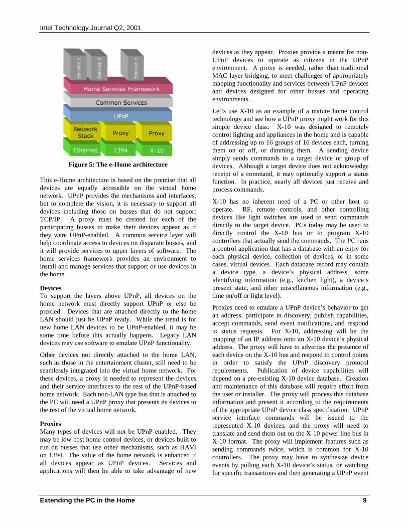
Intel Technology Journal Q2, 2001
Extending the PC in the Home 9
Figure 5: The e-Home architecture
This e-Home architecture is based on the premise that alldevices are equally accessible on the virtual homenetwork. UPnP provides the mechanisms and interfaces,but to complete the vision, it is necessary to support alldevices including those on busses that do not supportTCP/IP. A proxy must be created for each of theparticipating busses to make their devices appear as ifthey were UPnP-enabled. A common service layer willhelp coordinate access to devices on disparate busses, andit will provide services to upper layers of software. Thehome services framework provides an environment toinstall and manage services that support or use devices inthe home.
DevicesTo support the layers above UPnP, all devices on thehome network must directly support UPnP or else beproxied. Devices that are attached directly to the homeLAN should just be UPnP ready. While the trend is fornew home LAN devices to be UPnP-enabled, it may besome time before this actually happens. Legacy LANdevices may use software to emulate UPnP functionality.
Other devices not directly attached to the home LAN,such as those in the entertainment cluster, still need to beseamlessly integrated into the virtual home network. Forthese devices, a proxy is needed to represent the devicesand their service interfaces to the rest of the UPnP-basedhome network. Each non-LAN type bus that is attached tothe PC will need a UPnP proxy that presents its devices tothe rest of the virtual home network.
ProxiesMany types of devices will not be UPnP-enabled. Theymay be low-cost home control devices, or devices built torun on busses that use other mechanisms, such as HAVion 1394. The value of the home network is enhanced ifall devices appear as UPnP devices. Services andapplications will then be able to take advantage of new
devices as they appear. Proxies provide a means for non-UPnP devices to operate as citizens in the UPnPenvironment. A proxy is needed, rather than traditionalMAC layer bridging, to meet challenges of appropriatelymapping functionality and services between UPnP devicesand devices designed for other busses and operatingenvironments.
Let’s use X-10 as an example of a mature home controltechnology and see how a UPnP proxy might work for thissimple device class. X-10 was designed to remotelycontrol lighting and appliances in the home and is capableof addressing up to 16 groups of 16 devices each, turningthem on or off, or dimming them. A sending devicesimply sends commands to a target device or group ofdevices. Although a target device does not acknowledgereceipt of a command, it may optionally support a statusfunction. In practice, nearly all devices just receive andprocess commands.
X-10 has no inherent need of a PC or other host tooperate. RF, remote controls, and other controllingdevices like light switches are used to send commandsdirectly to the target device. PCs today may be used todirectly control the X-10 bus or to program X-10controllers that actually send the commands. The PC runsa control application that has a database with an entry foreach physical device, collection of devices, or in somecases, virtual devices. Each database record may containa device type, a device’s physical address, someidentifying information (e.g., kitchen light), a device’spresent state, and other miscellaneous information (e.g.,time on/off or light level).
Proxies need to emulate a UPnP device’s behavior to getan address, participate in discovery, publish capabilities,accept commands, send event notifications, and respondto status requests. For X-10, addressing will be themapping of an IP address onto an X-10 device’s physicaladdress. The proxy will have to advertise the presence ofeach device on the X-10 bus and respond to control pointsin order to satisfy the UPnP discovery protocolrequirements. Publication of device capabilities willdepend on a pre-existing X-10 device database. Creationand maintenance of this database will require effort fromthe user or installer. The proxy will process this databaseinformation and present it according to the requirementsof the appropriate UPnP device class specification. UPnPservice interface commands will be issued to therepresented X-10 devices, and the proxy will need totranslate and send them out on the X-10 power line bus inX-10 format. The proxy will implement features such assending commands twice, which is common for X-10controllers. The proxy may have to synthesize deviceevents by polling each X-10 device’s status, or watchingfor specific transactions and then generating a UPnP event
Intel Technology Journal Q2, 2001
Extending the PC in the Home 10
when an action causes a detectable event for the device.For X-10 devices that don’t have status reportingcapability, the proxy will have to track the device’s stateand attempt to synthesize the device’s status. Due to thelimitations of X-10 devices, it will not be possible to mapall UPnP behavior. More sophisticated home controlprotocols, such as a Simple Control Protocol (SCP), maymatch up better with UPnP.
BridgesBridging is another technology used to integrate deviceson different busses into one virtual home network andprovide a consistent view of devices to upper layers ofsoftware. A bridge is a hardware and software solutionthat resides between a device bus and the home network.It translates functionality at physical layers and above tomake devices appear to be citizens of the home network.
For example, a bridge resolves conflicting device needsfor isochronous versus asynchronous operation anddifferent requirements for data rates and latency, and itensures all devices can be detected and used in a uniformmanner.
Common Distributed ServicesAdditional services above the uniform device layercoordinate devices and provide common functionality thatwould otherwise be directly integrated into each device.Factoring out this common functionality as distributedservices on the home network will minimize developmenteffort, lower device costs, and increase interoperability.
There are two classes of services above the uniformdevice layer: device-specific services and device-independent services. Device-specific services providefunctionality related to the use of devices, such as wheredevices are, how they can be used together, and when theyare reserved. Device-independent services provide higherlevel functionality to applications in the home, such as theability to store and share data, and the ability to scale(transcode) data to the capabilities of particular clients.
Device-Specific ServicesUPnP provides control points the ability to uniquelyidentify and access devices. UPnP devices haveinformation associated with them that identifies devicedetails such as make, model, and serial number. UPnPcontrol points can use this information to locate specificdevices. Although devices provide this information, theuser would like to associate additional environmentalcontext with the device. For example, given two identicalMP3 players, a UPnP control point would recognize thetwo unique devices, while a user viewing the list of MP3players provided by the UPnP control point wouldn’t beable to determine which player belongs to the user.
Devices will be part of many different relationships in thehome, including ownership, location, and groupmembership.
In addition to associating ownership with devices, homeusers will also need the ability to associate locationinformation with devices. For example, two identical“Toshiba Model 3202a HDTVs” might be present in thehome, one in the family room and one in the bedroom. A“device location service” would maintain the locationinformation associated with each device.
UPnP devices also have no sense of what other devicesthey are supposed to work in concert with. A “groupingservice” would provide a way to associate related devices,giving them a group identity. For example, all outdoorperimeter lights could be made part of an “outdoorlighting” group. This group could then be controlled inunison, such as turning them all on or off. Each logicalgroup might be defined by function, such as theaudio/video components in the home; by location, such asthe backyard patio lights; or by other user-meaningfulattributes. Because these groups correspond to logicalrelationships, each device may belong to more than onegroup.
When there is more than one controlling entity present onthe home network, a “device scheduling service” isrequired to ensure exclusive use of devices. It should bepossible to schedule activity, reserving devices forspecific times.
Adding eventing to this mix of services allows the devicesin the home to be responsive, and to work together toachieve higher level functions, entering into the realm ofhome automation. For example, the “watching a movie”scenario might involve playing a movie, dimming thefamily room lights, setting the phone to auto-answer, andsetting the front door camera to automatically display onthe TV when the door bell rings.
Device-Independent ServicesThe second class of services above the uniform devicelayer is the “common services” layer. This layer provideshigher level services that are independent of devices. Acentral “storage service” would provide persistent storageto other services. A “sharing service” would provide theability to share content with other users, inside or outsidethe home. A “transcoding service” would provide theability to scale content to a specific target device.
The extended PC is well positioned to provide many ofthe common services to the other devices on the homenetwork. It has the computational power to serve as thecentral computing and communications engine for thehome. Products such as Personal Digital Assistants(PDAs) and digital cameras are examples of successful
Intel Technology Journal Q2, 2001
Extending the PC in the Home 11
products today that integrate with the PC, takingadvantage of its power to provide additional value-addedservices.
The Home Services FrameworkGiven a home network with a diverse array of devices anda powerful PC, the stage is set to animate the devices withapplications and services delivered into the home. Similarto today’s cable companies supplying programming to ahome set-top box, service providers will supply newproducts and services to the home over the Internet. Ahome gateway is the most likely host for these services,but there are other possible venues including an extendedPC desktop. Services will come in a variety of categoriessuch as entertainment, home monitoring and control, homesecurity, telephony, and information/content services. Toenable a new, service-based e-Home ecosystem to thrive,a standard way to package, deliver, integrate, and managethese home services is required. This is the focus of theHome Services Framework.
Services running in the framework will have differentcharacteristics. Some services will need to interact withdevices in the home in order to provide their service,perhaps automating some home functions; others willcommunicate with external services; still others mayprovide interfaces to service providers to perform somefunction in the home. The framework must allow forthese various types of communicating applications.
Features of the Home Services FrameworkThe framework’s primary responsibility is to allow aservice provider to manage the lifecycle of a servicehosted by the framework: install, start, stop, resume,uninstall, and so on. To do this, it will expose itsfunctionality as a Web service using standard protocolssuch as HTTP, SOAP, and XML. Using these standardprotocols will enable service providers’ client applicationsto leverage the many existing development tools andlibraries available.
To enable a responsive, loosely coupled set of interactingservices, the framework will define an eventing model.Services will be able to register for and receive eventsproduced by either the framework itself or other services.Services will also be able to define which events theyproduce.
There will be a hierarchy of services installed in theframework with interdependencies among them. Theframework will need to keep track of service dependencyinformation to provide the correct dependent services.
The framework will also provide a uniform run-timeenvironment to the services brought into the homenetwork. A uniform run-time environment will benefitboth service providers and home gateway vendors by
simplifying development and deployment of services. Itshould be possible to develop services in a variety ofprogramming languages, allowing service providers todevelop in their language of choice. In addition, theframework itself will be operating system independent,enabling deployment on a wide range of host systems.
The run-time environment will also provide common coreservices to applications running in the framework. Coreservices such as a log service, a secure channel service,and a storage service will enable installable services tobuild upon a common infrastructure, simplifying servicedevelopment.
The Consumer and the Service ProviderIt is also imperative to consider privacy issues for thehome services framework. To deliver services into thehome, the consumer and the service provider must enterinto a relationship. They each have different goals thatmust be satisfactorily resolved. Some consumers may notimplicitly trust outside entities such as service providers.However, because information and access must be givento a service provider in order to receive service, theconsumer must trust a home service provider to somedegree. Consumers may prefer to give the least amount ofinformation and access necessary to get the job done.However, unlike a tradesman coming into a home toperform some work, the service provider might havecontinual access to the home network. A solution mustbe provided that allows consumers to address their validprivacy concerns.
The consumer may also desire control over what goes oninside the home network, home gateway, and services. Ifsomething goes wrong, and there is a security breach,from which the consumer suffers a loss, the consumershould have some recourse. Consumers need a clearstatement of what each service does and an understandingof how their privacy will be guarded before they can makean informed decision about requesting a service.
If not properly guarded by the framework, unauthorizedinformation about the consumer or other service providerscould be improperly distributed; and information aboutdevices in the home, usage patterns, and so on could begleaned from the home network. Services brought into thehome potentially have access to information that could bevaluable and sold to third parties just as e-mail addressesare today.
To balance these forces, there should be some kind ofagreement between the consumer and the service providerdetailing their responsibilities. The customer should bemade aware of the potential risks to privacy andconfidentiality with the use of each service.
Intel Technology Journal Q2, 2001
Extending the PC in the Home 12
The service framework must be defensive, not implicitlytrusting services, and ensure that all services receive justenough information to perform their job.
SUMMARYThis paper has presented a vision of how the extended PCwill play a vital, growing role in the evolution of thee-Home. We have identified some of the necessaryinfrastructure needed to move towards a single virtualnetwork with common distributed services and aframework to deliver and manage services into the home.
This e-Home architecture provides the vision andarchitectural framework for the connected home of thefuture. A standard framework will encourage growth inthe home networking, computing, media, homeautomation, automotive, and cell phone industries. Thiswill benefit consumers and developers alike.
Intel and the industry will be at this new frontier.Together, we will be able to deliver new experiences andvalue to the consumer that build on the flexibility andpower of the extended PC. In turn, we will all benefit byenabling a thriving marketplace with large economies ofscale that allow all to participate. As developers of thedigital future, we in the industry should ensure that ourproducts are easy to set up and use, can seamlesslyinteroperate, and provide good value for the money,especially when dealing with the anytime, anywheree-Home. Meeting these goals will help all consumers tobenefit from technological advances and ensure that thePC industry remains at the forefront of the emerginge-Home.
ACKNOWLEDGMENTSWe thank our reviewers–Dave Andersen, Myron Hattig,Jamie Jason, Charlie Tai, and Jesse Walker–forcontributing their time and expertise to this paper. Wealso acknowledge the other members of the SolutionsEnabling Group and the Connected and Extended PC Labfor their input and review. Special thanks to Jim Edwardsfor his ideas, input, and in-depth review of this paper.
REFERENCES[1] Gartner Group, Inc., Remote Access in Europe:
Broadband Reality Getting Closer, January 19, 2001.
[2] The Strategis Group, Inc., Residential High-SpeedInternet: Cable Modems, DSL, and Fixed WirelessReport, January 2001.
More information can be found at the following Web sites:
1394 www.1394ta.org
802.11 www.ieee802.org/11
ACPI www.teleport.com/~acpi
APM www.microsoft.com/HWDEV/busbios/amp_12.htm
BroadbandHome, Inc.
www.peracom.com
CE-Bus www.cebus.org
HAVi www.HAVi.org
Home Plug www.homeplug.org
Home PNA www.homepna.org
Home RF www.homerf.org
IETF www.ietf.org
InstantlyAvailable PC
developer.intel.com/technology/IAPC
Jini www.jini.org
OSGi www.osgi.org
SCP www.microsoft.com/HOMENET/scp
UPnP www.upnp.org
X-10 www.x10.org
W3C, XML,and SOAP
www.w3c.org
AUTHORS’ BIOGRAPHIESCraig Merrick is an Architecture Development Managerwith Intel Corporation’s Solutions Enabling Group inHillsboro, Oregon where he is working on a newcomputing architecture for consumer devices. Hisinterests include digital photography and consumerproduct usability. He is a graduate of Eastern OregonState College and Oregon Institute of Technology. Hise-mail is [email protected].
Bob Dunstan is a Systems Architect with Intel’sConnected and Extended PC Lab working on platformarchitecture for the extended PC in the home. Hisinterests include OS power management and low-powertechnologies. Bob holds a B.S. and M.S. degree inComputer Science from Portland State University. Hise-mail is [email protected].
Michael Jeronimo is a Software Architect with IntelCorporation’s Connected and Extended PC Lab inHillsboro, Oregon where he is currently working on thespecification of a Home Services Framework. Hisinterests include software architecture, UML, design
Intel Technology Journal Q2, 2001
Extending the PC in the Home 13
patterns, and Internet security. Michael holds a B.A.degree in Computer Science from the University ofCalifornia at Santa Cruz. His e-mail [email protected].
Copyright © Intel Corporation 2001. This publicationwas downloaded from http://developer.intel.com/.
Legal notices athttp://developer.intel.com/sites/developer/tradmarx.htm.
Intel and SpeedStep are trademarks or registeredtrademarks of Intel Corporation or its subsidiaries in theUnited States and other countries.
Ultra-Wideband Technology for Short- or Medium-Range Wireless Communications 1
Ultra-Wideband Technology for Short- or Medium-Range Wireless Communications
Jeff Foerster, Intel Architecture Labs, Intel Corp. Evan Green, Intel Architecture Labs, Intel Corp.
Srinivasa Somayazulu, Intel Architecture Labs, Intel Corp. David Leeper, Intel Connected Products Division, Intel Corp.
Index words: UWB, wireless, communications, LAN, PAN
ABSTRACT Ultra-Wideband (UWB) technology is loosely defined as any wireless transmission scheme that occupies a bandwidth of more than 25% of a center frequency, or more than 1.5GHz. The Federal Communications Commission (FCC) is currently working on setting emissions limits that would allow UWB communication systems to be deployed on an unlicensed basis following the Part 15.209 rules for radiated emissions of intentional radiators, the same rules governing the radiated emissions from home computers, for example. This rule change would allow UWB-enabled devices to overlay existing narrowband systems, which is currently not allowed, and result in a much more efficient use of the available spectrum. Devices could, in essence, fill in the unused portions of the frequency spectrum in any particular location.
These recent developments by the FCC give Intel a unique opportunity to develop equipment that could potentially take advantage of the vast amount of usable spectrum that exists in the wireless space, and that could provide an engine to drive the future high-rate applications that are being conceived throughout this industry.
Intel® Architecture Labs (IAL) is currently researching UWB technology in order to better understand its benefits, limitations, and technical challenges when used for high-rate communications. This paper introduces the reader to this technology, from potential applications to regulatory hurdles, to possible implementations and future challenges.
INTRODUCTION Ultra-Wideband (UWB) technology has been around since the 1980s, but it has been mainly used for radar-based applications until now (see [1] and the references
therein), because of the wideband nature of the signal that results in very accurate timing information. However, due to recent developments in high-speed switching technology, UWB is becoming more attractive for low-cost consumer communications applications (as detailed in the “Implementation Advantages” section of this paper). Intel Architecture Labs (IAL) is currently working on an internally funded research project whose intent is to further explore the potential benefits and future challenges for extending UWB technology into the high-rate communications arena.
Although the term Ultra-Wideband (UWB) is not very descriptive, it does help to separate this technology from more traditional “narrowband” systems as well as newer “wideband” systems typically referred to in the literature describing the future 3G cellular technology. There are two main differences between UWB and other “narrowband” or “wideband” systems. First, the bandwidth of UWB systems, as defined by the Federal Communications Commission (FCC) in [2], is more than 25% of a center frequency or more than 1.5GHz. Clearly, this bandwidth is much greater than the bandwidth used by any current technology for communication. Second, UWB is typically implemented in a carrierless fashion. Conventional “narrowband” and “wideband” systems use Radio Frequency (RF) carriers to move the signal in the frequency domain from baseband to the actual carrier frequency where the system is allowed to operate. Conversely, UWB implementations can directly modulate an “impulse” that has a very sharp rise and fall time, thus resulting in a waveform that occupies several GHz of bandwidth. Although there are other methods for generating a UWB waveform (using a chirped signal, for example), in this paper, we focus on the impulse-based UWB waveform–due to its simplicity. But, first, a breakdown of how this paper is organized.
Intel Technology Journal Q2, 2001
Ultra-Wideband Technology for Short- or Medium-Range Wireless Communications 2
The first section looks at UWB technology from the high-level perspective of how this technology compares with other current and future wireless alternatives. Next, we describe the current state of the regulatory process, where UWB transmissions are under consideration for being made legal on an unlicensed basis. Then, some implementation advantages of UWB systems are discussed that distinguish UWB transceiver architectures from more conventional “narrowband” systems. After this, we illustrate the throughput vs. distance characteristics for an example UWB system.
The high data rates afforded by UWB systems will tend to favor applications such as video distribution and/or video teleconferencing for which Quality of Service (QoS) will be very important. So, in addition to describing the physical layer attributes of UWB systems, it’s important to keep in mind the Medium Access Control (MAC) layer as well. Therefore, we have also devoted a section to describing the current mechanisms that exist to support the required QoS for these high-rate applications. Finally, we conclude with a summary of the benefits of UWB and suggest some future challenges that are currently being investigated by IAL.
WIRELESS ALTERNATIVES In order to understand where UWB fits in with the current trends in wireless communications, we need to consider the general problem that communications systems try to solve. Specifically, if wireless were an ideal medium, we could use it to send
1. a lot of data,
2. very far,
3. very fast,
4. for many users,
5. all at once.
Unfortunately, it is impossible to achieve all five attributes simultaneously for systems supporting unique, private, two-way communication streams; one or more have to be given up if the others are to do well. Original wireless systems were built to bridge large distances in order to link two parties together. However, recent history of radio shows a clear trend toward improving on the other four attributes at the expense of distance. Cellular telephony is the most obvious example, covering distances of 30 kilometers to as little as 300 meters. Shorter distances allow for spectrum reuse, thereby serving more users, and the systems are practical because they are supported by an underlying wired infrastructure–the telephone network in the case of cellular. In the past few years, even shorter range systems, from 10 to 100 meters, have begun emerging, driven primarily by data applications. Here, the Internet is the underlying wired
infrastructure, rather than the telephone network. Many expect the combination of short-range wireless and wired Internet to become a fast-growing complement to next-generation cellular systems for data, voice, audio, and video. Four trends are driving short-range wireless in general and ultra-wideband in particular:
1. The growing demand for wireless data capability in portable devices at higher bandwidth but lower in cost and power consumption than currently available.
2. Crowding in the spectrum that is segmented and licensed by regulatory authorities in traditional ways.
3. The growth of high-speed wired access to the Internet in enterprises, homes, and public spaces.
4. Shrinking semiconductor cost and power consumption for signal processing.
Trends 1 and 2 favor systems that offer not just high-peak bit rates, but high spatial capacity1 as well, where spatial capacity is defined as bits/sec/square-meter. Just as the telephone network enabled cellular telephony, Trend 3 makes possible high-bandwidth, in-building service provision to low-power portable devices using short-range wireless standards like Bluetooth∗ (http://www.bluetooth.com) and IEEE 802.11 (http://grouper.ieee.org/groups/802). Finally, Trend 4 makes possible the use of signal processing techniques that would have been impractical only a few years ago. It is this final trend that makes Ultra-Wideband (UWB) technology practical.
When used as intended, the emerging short- and medium-range wireless standards vary widely in their implicit spatial capacities. For example:
• IEEE 802.11b has a rated operating range of 100 meters. In the 2.4GHz ISM band, there is about 80MHz of useable spectrum. Hence, in a circle with a radius of 100 meters, three 22MHz IEEE 802.11b
1 The term spatial capacity has been used by many, including Prof. Jan Rabaey at the University of California, Berkeley. An equivalent and more descriptive term might be spatial efficiency. The late Marc Weiser, Chief Technologist of Xerox PARC, lectured on the importance of spatial capacity in 1996 (http://www.ubiq.com/hypertext/weiser/NomadicInteractive/), though at the time he focused on infrared as the medium and bits/sec/cubic-meter as the metric. We will use square-meter in this paper since the relevant coverage area is usually two-dimensional rather than three-dimensional. ∗ Other names and brands may be claimed as the property of others.
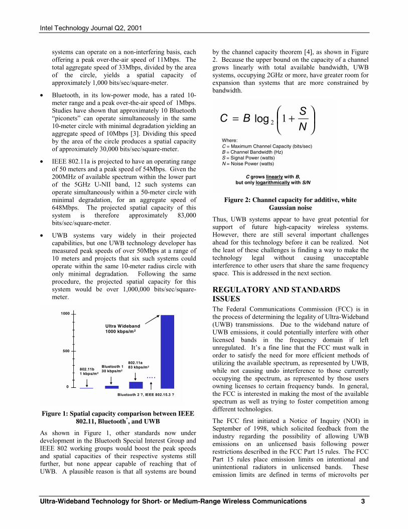
Intel Technology Journal Q2, 2001
Ultra-Wideband Technology for Short- or Medium-Range Wireless Communications 3
systems can operate on a non-interfering basis, each offering a peak over-the-air speed of 11Mbps. The total aggregate speed of 33Mbps, divided by the area of the circle, yields a spatial capacity of approximately 1,000 bits/sec/square-meter.
• Bluetooth, in its low-power mode, has a rated 10-meter range and a peak over-the-air speed of 1Mbps. Studies have shown that approximately 10 Bluetooth “piconets” can operate simultaneously in the same 10-meter circle with minimal degradation yielding an aggregate speed of 10Mbps [3]. Dividing this speed by the area of the circle produces a spatial capacity of approximately 30,000 bits/sec/square-meter.
• IEEE 802.11a is projected to have an operating range of 50 meters and a peak speed of 54Mbps. Given the 200MHz of available spectrum within the lower part of the 5GHz U-NII band, 12 such systems can operate simultaneously within a 50-meter circle with minimal degradation, for an aggregate speed of 648Mbps. The projected spatial capacity of this system is therefore approximately 83,000 bits/sec/square-meter.
• UWB systems vary widely in their projected capabilities, but one UWB technology developer has measured peak speeds of over 50Mbps at a range of 10 meters and projects that six such systems could operate within the same 10-meter radius circle with only minimal degradation. Following the same procedure, the projected spatial capacity for this system would be over 1,000,000 bits/sec/square-meter.
1000
500
802.11b1 kbps/m2
0
Bluetooth 130 kbps/m2
Ultra Wideband1000 kbps/m2
802.11a83 kbps/m2
….
Bluetooth 2 ?, IEEE 802.15.3 ?
Figure 1: Spatial capacity comparison between IEEE 802.11, Bluetooth*, and UWB
As shown in Figure 1, other standards now under development in the Bluetooth Special Interest Group and IEEE 802 working groups would boost the peak speeds and spatial capacities of their respective systems still further, but none appear capable of reaching that of UWB. A plausible reason is that all systems are bound
by the channel capacity theorem [4], as shown in Figure 2. Because the upper bound on the capacity of a channel grows linearly with total available bandwidth, UWB systems, occupying 2GHz or more, have greater room for expansion than systems that are more constrained by bandwidth.
Where:C = Maximum Channel Capacity (bits/sec)B = Channel Bandwidth (Hz)S = Signal Power (watts)N = Noise Power (watts)
+=
NS
BC 12log
C grows linearly with B, but only logarithmically with S/N
Figure 2: Channel capacity for additive, white Gaussian noise
Thus, UWB systems appear to have great potential for support of future high-capacity wireless systems. However, there are still several important challenges ahead for this technology before it can be realized. Not the least of these challenges is finding a way to make the technology legal without causing unacceptable interference to other users that share the same frequency space. This is addressed in the next section.
REGULATORY AND STANDARDS ISSUES The Federal Communications Commission (FCC) is in the process of determining the legality of Ultra-Wideband (UWB) transmissions. Due to the wideband nature of UWB emissions, it could potentially interfere with other licensed bands in the frequency domain if left unregulated. It’s a fine line that the FCC must walk in order to satisfy the need for more efficient methods of utilizing the available spectrum, as represented by UWB, while not causing undo interference to those currently occupying the spectrum, as represented by those users owning licenses to certain frequency bands. In general, the FCC is interested in making the most of the available spectrum as well as trying to foster competition among different technologies.
The FCC first initiated a Notice of Inquiry (NOI) in September of 1998, which solicited feedback from the industry regarding the possibility of allowing UWB emissions on an unlicensed basis following power restrictions described in the FCC Part 15 rules. The FCC Part 15 rules place emission limits on intentional and unintentional radiators in unlicensed bands. These emission limits are defined in terms of microvolts per
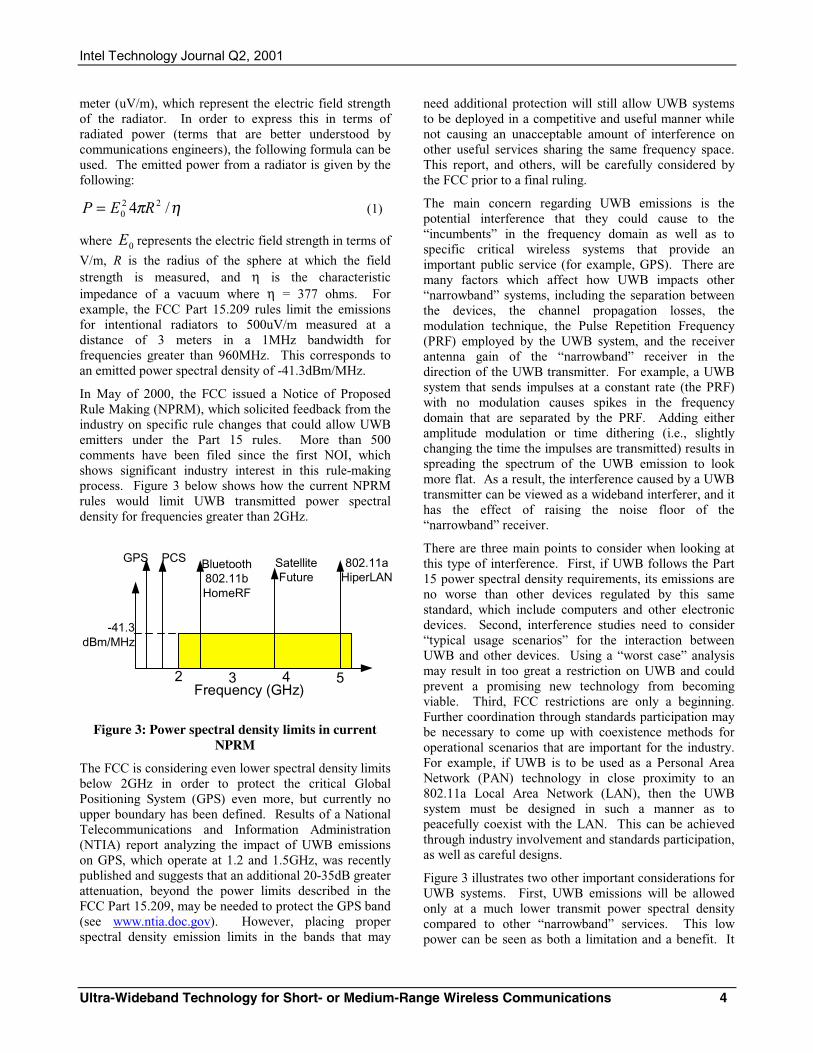
Intel Technology Journal Q2, 2001
Ultra-Wideband Technology for Short- or Medium-Range Wireless Communications 4
meter (uV/m), which represent the electric field strength of the radiator. In order to express this in terms of radiated power (terms that are better understood by communications engineers), the following formula can be used. The emitted power from a radiator is given by the following:
ηπ /4 220 REP = (1)
where 0E represents the electric field strength in terms of
V/m, R is the radius of the sphere at which the field strength is measured, and η is the characteristic impedance of a vacuum where η = 377 ohms. For example, the FCC Part 15.209 rules limit the emissions for intentional radiators to 500uV/m measured at a distance of 3 meters in a 1MHz bandwidth for frequencies greater than 960MHz. This corresponds to an emitted power spectral density of -41.3dBm/MHz.
In May of 2000, the FCC issued a Notice of Proposed Rule Making (NPRM), which solicited feedback from the industry on specific rule changes that could allow UWB emitters under the Part 15 rules. More than 500 comments have been filed since the first NOI, which shows significant industry interest in this rule-making process. Figure 3 below shows how the current NPRM rules would limit UWB transmitted power spectral density for frequencies greater than 2GHz.
Frequency (GHz)
-41.3dBm/MHz
2 3 4 5
GPS Bluetooth802.11bHomeRF
802.11aHiperLAN
PCS SatelliteFuture
Figure 3: Power spectral density limits in current NPRM
The FCC is considering even lower spectral density limits below 2GHz in order to protect the critical Global Positioning System (GPS) even more, but currently no upper boundary has been defined. Results of a National Telecommunications and Information Administration (NTIA) report analyzing the impact of UWB emissions on GPS, which operate at 1.2 and 1.5GHz, was recently published and suggests that an additional 20-35dB greater attenuation, beyond the power limits described in the FCC Part 15.209, may be needed to protect the GPS band (see www.ntia.doc.gov). However, placing proper spectral density emission limits in the bands that may
need additional protection will still allow UWB systems to be deployed in a competitive and useful manner while not causing an unacceptable amount of interference on other useful services sharing the same frequency space. This report, and others, will be carefully considered by the FCC prior to a final ruling.
The main concern regarding UWB emissions is the potential interference that they could cause to the “incumbents” in the frequency domain as well as to specific critical wireless systems that provide an important public service (for example, GPS). There are many factors which affect how UWB impacts other “narrowband” systems, including the separation between the devices, the channel propagation losses, the modulation technique, the Pulse Repetition Frequency (PRF) employed by the UWB system, and the receiver antenna gain of the “narrowband” receiver in the direction of the UWB transmitter. For example, a UWB system that sends impulses at a constant rate (the PRF) with no modulation causes spikes in the frequency domain that are separated by the PRF. Adding either amplitude modulation or time dithering (i.e., slightly changing the time the impulses are transmitted) results in spreading the spectrum of the UWB emission to look more flat. As a result, the interference caused by a UWB transmitter can be viewed as a wideband interferer, and it has the effect of raising the noise floor of the “narrowband” receiver.
There are three main points to consider when looking at this type of interference. First, if UWB follows the Part 15 power spectral density requirements, its emissions are no worse than other devices regulated by this same standard, which include computers and other electronic devices. Second, interference studies need to consider “typical usage scenarios” for the interaction between UWB and other devices. Using a “worst case” analysis may result in too great a restriction on UWB and could prevent a promising new technology from becoming viable. Third, FCC restrictions are only a beginning. Further coordination through standards participation may be necessary to come up with coexistence methods for operational scenarios that are important for the industry. For example, if UWB is to be used as a Personal Area Network (PAN) technology in close proximity to an 802.11a Local Area Network (LAN), then the UWB system must be designed in such a manner as to peacefully coexist with the LAN. This can be achieved through industry involvement and standards participation, as well as careful designs.
Figure 3 illustrates two other important considerations for UWB systems. First, UWB emissions will be allowed only at a much lower transmit power spectral density compared to other “narrowband” services. This low power can be seen as both a limitation and a benefit. It
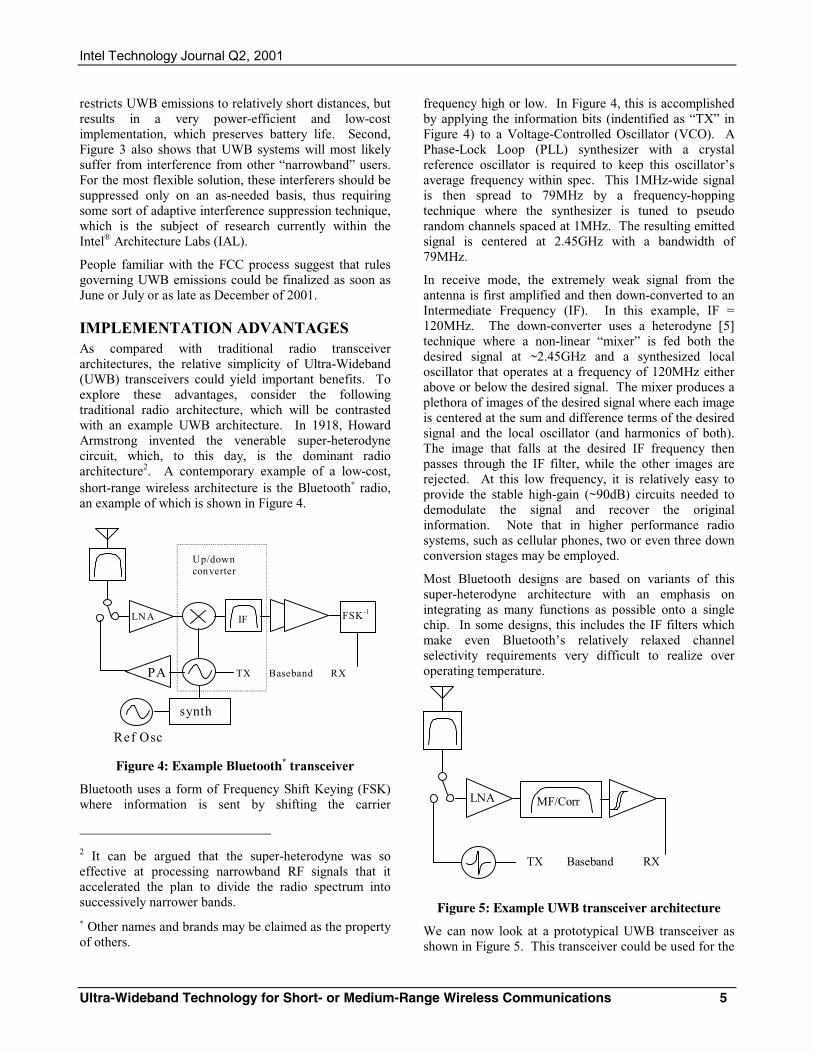
Intel Technology Journal Q2, 2001
Ultra-Wideband Technology for Short- or Medium-Range Wireless Communications 5
restricts UWB emissions to relatively short distances, but results in a very power-efficient and low-cost implementation, which preserves battery life. Second, Figure 3 also shows that UWB systems will most likely suffer from interference from other “narrowband” users. For the most flexible solution, these interferers should be suppressed only on an as-needed basis, thus requiring some sort of adaptive interference suppression technique, which is the subject of research currently within the Intel® Architecture Labs (IAL).
People familiar with the FCC process suggest that rules governing UWB emissions could be finalized as soon as June or July or as late as December of 2001.
IMPLEMENTATION ADVANTAGES As compared with traditional radio transceiver architectures, the relative simplicity of Ultra-Wideband (UWB) transceivers could yield important benefits. To explore these advantages, consider the following traditional radio architecture, which will be contrasted with an example UWB architecture. In 1918, Howard Armstrong invented the venerable super-heterodyne circuit, which, to this day, is the dominant radio architecture2. A contemporary example of a low-cost, short-range wireless architecture is the Bluetooth∗ radio, an example of which is shown in Figure 4.
Figure 4: Example Bluetooth* transceiver
Bluetooth uses a form of Frequency Shift Keying (FSK) where information is sent by shifting the carrier
2 It can be argued that the super-heterodyne was so effective at processing narrowband RF signals that it accelerated the plan to divide the radio spectrum into successively narrower bands. ∗ Other names and brands may be claimed as the property of others.
frequency high or low. In Figure 4, this is accomplished by applying the information bits (indentified as “TX” in Figure 4) to a Voltage-Controlled Oscillator (VCO). A Phase-Lock Loop (PLL) synthesizer with a crystal reference oscillator is required to keep this oscillator’s average frequency within spec. This 1MHz-wide signal is then spread to 79MHz by a frequency-hopping technique where the synthesizer is tuned to pseudo random channels spaced at 1MHz. The resulting emitted signal is centered at 2.45GHz with a bandwidth of 79MHz.
In receive mode, the extremely weak signal from the antenna is first amplified and then down-converted to an Intermediate Frequency (IF). In this example, IF = 120MHz. The down-converter uses a heterodyne [5] technique where a non-linear “mixer” is fed both the desired signal at ~2.45GHz and a synthesized local oscillator that operates at a frequency of 120MHz either above or below the desired signal. The mixer produces a plethora of images of the desired signal where each image is centered at the sum and difference terms of the desired signal and the local oscillator (and harmonics of both). The image that falls at the desired IF frequency then passes through the IF filter, while the other images are rejected. At this low frequency, it is relatively easy to provide the stable high-gain (~90dB) circuits needed to demodulate the signal and recover the original information. Note that in higher performance radio systems, such as cellular phones, two or even three down conversion stages may be employed.
Most Bluetooth designs are based on variants of this super-heterodyne architecture with an emphasis on integrating as many functions as possible onto a single chip. In some designs, this includes the IF filters which make even Bluetooth’s relatively relaxed channel selectivity requirements very difficult to realize over operating temperature.
Figure 5: Example UWB transceiver architecture
We can now look at a prototypical UWB transceiver as shown in Figure 5. This transceiver could be used for the
LNA MF/Corr
TX Baseband RX
Ref Osc
synth
FSK-1
TX Baseband RX PA
LNA IF
Up/down converter
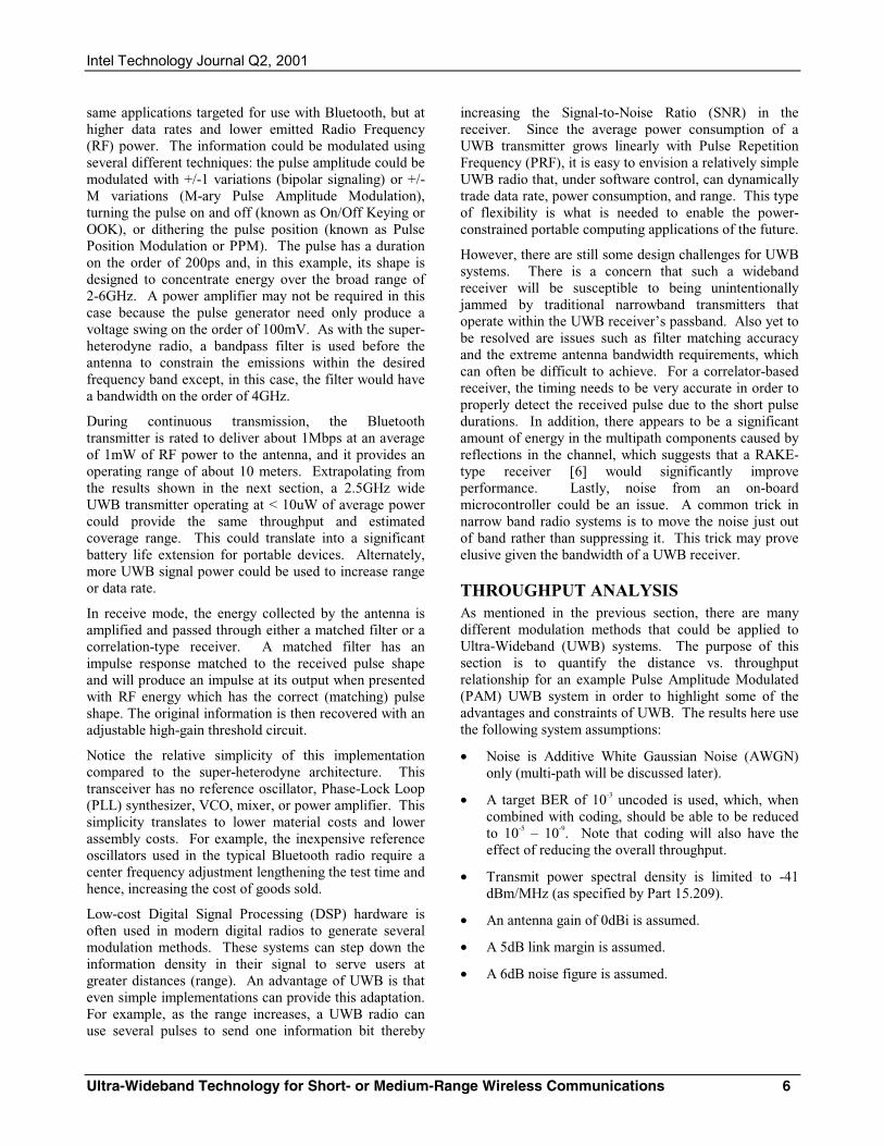
Intel Technology Journal Q2, 2001
Ultra-Wideband Technology for Short- or Medium-Range Wireless Communications 6
same applications targeted for use with Bluetooth, but at higher data rates and lower emitted Radio Frequency (RF) power. The information could be modulated using several different techniques: the pulse amplitude could be modulated with +/-1 variations (bipolar signaling) or +/- M variations (M-ary Pulse Amplitude Modulation), turning the pulse on and off (known as On/Off Keying or OOK), or dithering the pulse position (known as Pulse Position Modulation or PPM). The pulse has a duration on the order of 200ps and, in this example, its shape is designed to concentrate energy over the broad range of 2-6GHz. A power amplifier may not be required in this case because the pulse generator need only produce a voltage swing on the order of 100mV. As with the super-heterodyne radio, a bandpass filter is used before the antenna to constrain the emissions within the desired frequency band except, in this case, the filter would have a bandwidth on the order of 4GHz.
During continuous transmission, the Bluetooth transmitter is rated to deliver about 1Mbps at an average of 1mW of RF power to the antenna, and it provides an operating range of about 10 meters. Extrapolating from the results shown in the next section, a 2.5GHz wide UWB transmitter operating at < 10uW of average power could provide the same throughput and estimated coverage range. This could translate into a significant battery life extension for portable devices. Alternately, more UWB signal power could be used to increase range or data rate.
In receive mode, the energy collected by the antenna is amplified and passed through either a matched filter or a correlation-type receiver. A matched filter has an impulse response matched to the received pulse shape and will produce an impulse at its output when presented with RF energy which has the correct (matching) pulse shape. The original information is then recovered with an adjustable high-gain threshold circuit.
Notice the relative simplicity of this implementation compared to the super-heterodyne architecture. This transceiver has no reference oscillator, Phase-Lock Loop (PLL) synthesizer, VCO, mixer, or power amplifier. This simplicity translates to lower material costs and lower assembly costs. For example, the inexpensive reference oscillators used in the typical Bluetooth radio require a center frequency adjustment lengthening the test time and hence, increasing the cost of goods sold.
Low-cost Digital Signal Processing (DSP) hardware is often used in modern digital radios to generate several modulation methods. These systems can step down the information density in their signal to serve users at greater distances (range). An advantage of UWB is that even simple implementations can provide this adaptation. For example, as the range increases, a UWB radio can use several pulses to send one information bit thereby
increasing the Signal-to-Noise Ratio (SNR) in the receiver. Since the average power consumption of a UWB transmitter grows linearly with Pulse Repetition Frequency (PRF), it is easy to envision a relatively simple UWB radio that, under software control, can dynamically trade data rate, power consumption, and range. This type of flexibility is what is needed to enable the power-constrained portable computing applications of the future.
However, there are still some design challenges for UWB systems. There is a concern that such a wideband receiver will be susceptible to being unintentionally jammed by traditional narrowband transmitters that operate within the UWB receiver’s passband. Also yet to be resolved are issues such as filter matching accuracy and the extreme antenna bandwidth requirements, which can often be difficult to achieve. For a correlator-based receiver, the timing needs to be very accurate in order to properly detect the received pulse due to the short pulse durations. In addition, there appears to be a significant amount of energy in the multipath components caused by reflections in the channel, which suggests that a RAKE-type receiver [6] would significantly improve performance. Lastly, noise from an on-board microcontroller could be an issue. A common trick in narrow band radio systems is to move the noise just out of band rather than suppressing it. This trick may prove elusive given the bandwidth of a UWB receiver.
THROUGHPUT ANALYSIS As mentioned in the previous section, there are many different modulation methods that could be applied to Ultra-Wideband (UWB) systems. The purpose of this section is to quantify the distance vs. throughput relationship for an example Pulse Amplitude Modulated (PAM) UWB system in order to highlight some of the advantages and constraints of UWB. The results here use the following system assumptions:
• Noise is Additive White Gaussian Noise (AWGN) only (multi-path will be discussed later).
• A target BER of 10-3 uncoded is used, which, when combined with coding, should be able to be reduced to 10-5 – 10-9. Note that coding will also have the effect of reducing the overall throughput.
• Transmit power spectral density is limited to -41 dBm/MHz (as specified by Part 15.209).
• An antenna gain of 0dBi is assumed.
• A 5dB link margin is assumed.
• A 6dB noise figure is assumed.
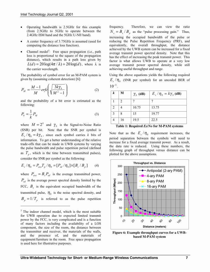
Intel Technology Journal Q2, 2001
Ultra-Wideband Technology for Short- or Medium-Range Wireless Communications 7
• Operating bandwidth is 2.5GHz for this example (from 2.5GHz to 5GHz to operate between the 2.4GHz ISM band and the 5GHz U-NII band).
• A center frequency of 3.75GHz is assumed (used for computing the distance loss function).
• Channel model3: Free space propagation (i.e., path loss is proportional to the square of the propagation distance), which results in a path loss given by
)log(20)/4log(20)( ddL += λπ , where λ is the carrier wavelength.
The probability of symbol error for an M-PAM system is given by (assuming coherent detection) [6]:
−
−=1
312M
kerfc
M
MP b
M
γ (2)
and the probability of a bit error is estimated as the following:
Mb Pk
P1= (3)
where kM 2= and bγ is the Signal-to-Noise Ratio
(SNR) per bit. Note that the SNR per symbol is
bs kE γη =0/ , since each symbol carries k bits of
information. To get a better understanding of the relative trade-offs that can be made in UWB systems by varying the pulse bandwidth and pulse repetition period (defined
as pT , which is the time between transmitted pulses),
consider the SNR per symbol as the following:
]/[]/[// 000 pssdpaves BBPTPE ×== ηηη (4)
where sdsave PBP = is the average transmitted power,
sdP is the average power spectral density limited by the
FCC, sB is the equivalent occupied bandwidth of the
transmitted pulse, 0η is the noise spectral density, and
pp TB /1= is referred to as the pulse repetition
3 The indoor channel model, which is the most suitable for UWB operation due to expected limited transmit power by the FCC, is very complicated and is a function of many factors including the availability of a LOS component, the size of the room, the distance between the transmitter and receiver, the materials of the walls, and the presence of, and the materials of equipment/furniture in the room. Free space propagation is used here for illustrative purposes.
frequency. Therefore, we can view the ratio
pss BBN /= as the “pulse processing gain.” Thus,
increasing the occupied bandwidth of the pulse or reducing the Pulse Repetition Frequency (PRF), and equivalently, the overall throughput, the distance achieved by the UWB system can be increased for a fixed average transmit power spectral density. Note that this has the effect of increasing the peak transmit power. This factor is what allows UWB to operate at a very low average transmit power spectral density, while still achieving useful throughput and range.
Using the above equations yields the following required
0/ηsE (SNR per symbol) for an uncoded BER of 310− .
k M bγ (dB) bs kE γη =0/ (dB)
1 2 7 7
2 4 10.75 13.75
3 8 15 19.77
4 16 19.5 22.5
Table 1: Required Es/No for M-PAM systems
Note that as the 0/ηsE requirement increases, the
period separation between the symbols will need to increase for a fixed average transmit power. As a result, the data rate is reduced. Using these numbers, the following graph of throughput versus distance can be plotted for the above assumptions.
Throughput vs. Distance
0
50
100
150
200
250
300
10 20 30 40 60 80 100
Distance (meters)
Th
rou
gh
pu
t (M
bp
s)
Antipodal (2-ary PAM)4-ary PAM8-ary PAM16-ary PAM
Figure 6: Example throughput curves for a UWB-based M-PAM system
Intel Technology Journal Q2, 2001
Ultra-Wideband Technology for Short- or Medium-Range Wireless Communications 8
Clearly, the above graph shows that UWB really provides the greatest throughput at the closer distances. Of course there are other methods for improving the throughput vs. distance relationship, including increased antenna gain, improved coding gain, reduced noise figure, and greater occupied bandwidth. Also note that a more realistic channel model may have path loss exponentials on the order of 2.8-3 for typical indoor channels that must also be considered.
The results here suggest that higher order M-PAM systems do not improve the throughput as much as using lower order 2-PAM with a higher PRF. This can be understood by recalling that PAM is a very spectral efficient modulation technique, but not necessarily very power efficient. For UWB systems, the spectrum is determined by the shape of the pulse rather than the symbol rate. Therefore, for an AWGN channel, it is reasonable to expect that lower order PAM would result in the best performance. However, if a multi-path channel is considered, the 2-PAM system would potentially experience inter-symbol interference, which could potentially limit its throughput, while the higher order systems with greater pulse repetition periods would be impacted less. More information regarding the performance of M-PAM systems in a multi-path channel can be found in [7].
One of the important advantages of UWB systems is their inherent robustness to multi-path fading [8]. Heuristically, this can be explained as follows. Multi-path fading results from the destructive interference caused by the sum of several received paths that may be out of phase with each other. The very narrow pulses of UWB waveforms result in the multiple reflections caused by the channel being resolved independently rather than combining destructively at the receiver. As a result, the time-varying fading that plagues “narrowband” systems is significantly reduced by the nature of the UWB waveform.
Clearly, the overall system performance is significantly impacted by the channel propagation and multi-path model and assumptions. The researchers in the Intel® Architecture Labs (IAL) are working with university and industry partners to get a better understanding of the UWB propagation environment in order to more accurately predict the performance of UWB systems. This information can also be used to more optimally design transmitters and receivers.
MEDIA ACCESS CONTROL (MAC) ISSUES As the evolution of wireless networks continues to offer higher and higher data rates, a similar natural evolution is occurring in the kinds of applications that are being envisioned for these networks. Current low data-rate
Wireless Local Area Networks (WLANs) and Wireless Personal Area Networks (WPANs), which have data rates of ~1-10Mbps, are typically used for applications such as packet-switched data and cordless voice telephony, using Time Division Multiple Access (TDMA) voice circuits. Example technologies supporting these applications are the IEEE 802.11b (Wi-Fi)*, Bluetooth∗, and HomeRF* networking standards. As the IEEE 802.11 and ETSI BRAN HiperLAN/2* standards (the European equivalent of 802.11) have added physical layer specifications with raw data rates up to 54Mbps, the application space is enlarging to include audio/video applications that are enabled by these higher data rates. These diverse traffic types all have different requirements in terms of the service parameters that quantify the network performance for a user of each of those applications. Thus, for example, voice telephony and video teleconferencing applications place tough demands on the latency and jitter performance. Audio/video applications require large amounts of bandwidth and may need close synchronization (e.g., connecting stereo speakers in a surround sound system). Ultra-Wideband (UWB) systems, with their potential for extremely large data rates over short distances, are naturally going to be used for networking these kinds of high-bandwidth/delay- critical data sources and sinks. Hence, it would be natural to look at the approaches to the MAC design undertaken in these other standards when considering the MAC layer design for UWB systems.
The most important functions of the MAC layer for a wireless network include controlling channel access, maintaining Quality of Service (QoS), and providing security. Wireless links have characteristics that differ from those of fixed links, such as high packet loss rate, bursts of packet loss, packet re-ordering, and large packet delay and packet delay variation. Furthermore, the wireless link characteristics are not constant and may vary in time and place. The mobility of users poses additional requirements, as the end-to-end path may be changed when users change their point of attachment. Users expect to receive the same QoS after they have changed their point of attachment. This implies that the new end-to-end path should also support the existing QoS (i.e., a reservation on the new path may be required), and problems arise when the new path cannot support the required QoS. Security is obviously an important consideration in wireless networks because, unlike wired networks, the overlaps between networks cannot be controlled. In addition, unauthorized users can also eavesdrop on transmissions. Security is handled through a combination of different means at the MAC layer, and
∗ Other brands and names are the property of their respective owners.
Intel Technology Journal Q2, 2001
Ultra-Wideband Technology for Short- or Medium-Range Wireless Communications 9
also may include physical layer properties of the network. In this section, we restrict ourselves to the channel access and QoS functions, and we first look at some current approaches being considered in the standards-setting committees.
In the IEEE 802.11 TGe committee, there is an ongoing project to enhance the 802.11 MAC to provide for prioritized channel access and QoS. The basic channel access function of the 802.11 MAC is the Distributed Coordination Function (DCF), with an optional mode called the Point Coordination Function (PCF) built atop the DCF, which offers a centralized, polling-based communication between stations and a point coordinator. With the PCF, the point coordinator defines a Contention-Free Period (CFP) during which the stations are polled and a Contention Period (CP) during which the normal DCF channel access mechanism holds. A periodic beacon identifies the start of the CFP and the duration. At the current stage, different prioritized channel access mechanisms for an Enhanced DCF (EDCF) mode are being considered. The EDCF mode provides for treating the priorities of different packets (encoded according to 3-bit traffic category tags) by giving them statistically fair access to the medium. This means that packets from the same priority class contend for the medium on an equal basis according to the 802.11 MAC rules. Packets from different priority classes contend on a weighted basis, where the higher priority packets get a higher probability of success for channel access. Thus, higher priority classes cannot, in principle, choke transfer of lower priority class traffic. In addition to the EDCF modes, a type of point coordination function called the Hybrid Coordination Function (HCF) is also being proposed. The HCF mechanism provides for contention-free and controlled-contention transfers during any part of the frame (i.e., CFP or CP) by allowing the Hybrid Coordinator (HC) to generate bursts of CFPs, as opposed to a monolithic CFP. Thus, the HC can essentially create a number of “mini-CFPs” within the CP, as needed to meet traffic specs. Using this means the HCF promises to provide a flexible scheme where, for example, traffic classes that require periodic transmission opportunities can be accommodated within the CP or the CFP. Traffic that is burstier in nature is handled through the prioritized EDCF mechanism during the CP. In addition, this concept of CFP bursts is expected to mitigate the inter-cell interference that is a problem with the centrally controlled PCF mode when the cells are overlapping in extent.
HiperLAN/2 (HL2) systems, the European counterpart of 802.11, present a very different approach to the MAC and QoS design for high-data rate systems. Where the 802.11 MAC has roots in Ethernet and IP, and the QoS enhancements are seeking to maintain backward compatibility, the HL2 MAC is based on Wireless ATM
concepts and does not have these backwards compatibility requirements. HL2 differs from 802.11 fundamentally in that it uses very short, fixed-length packets, a centrally controlled random access resource reservation channel, and a TDMA kind of resource allocation that is based on successful resource reservation attempts. This kind of architecture potentially offers good QoS performance for streaming sources. However, many feel that the complexity of implementation is quite high compared with the 802.11 MAC. In addition, some studies have shown that in uncoordinated deployment scenarios, inter-cell interference from overlapping cells can be a big problem for the centrally controlled HL2 systems.
In designing a MAC for high-data rate UWB systems, some of the particular properties of the transmission system will obviously dictate many of the design choices. UWB systems offer some unique abilities such as precise position/timing location. This can be exploited at the MAC layer, for example, to synchronize the received packets at different receivers of a multi-cast network (perhaps multiple audio speakers/video displays). UWB systems are also flexible, trading off throughput for range since the Pulse Repetition Frequency (PRF) and the peak pulse power can vary inversely to provide for constant average power. This can be used at the MAC layer to provide for signaling of different data rates on a per-packet or per-link basis, depending on the range of that particular communication. Ultra-Wideband (UWB) systems could also be designed using spread spectrum codes, which may offer better coexistence with other UWB systems, so that unplanned deployment of UWB networks in homes is facilitated. At the MAC layer, this may also result in different choices being available–notably, the problems that centrally coordinated MAC schemes face with overlapping networks may be mitigated. Another choice at the MAC layer that is available is the use of Code Division Multiple Access (CDMA) in addition to TDMA or carrier sense multiple access (CSMA). CDMA also offers the possibility of using techniques such as multi-user detection to boost the system capacity.
One promising application that has been envisioned for UWB is cable replacement for audio/video devices, which would be using wired IEEE 1394 connections (see [9] for more details on IEEE 1394). This could serve two functions: it could act as a wireless “bridge” between clusters of 1394 nodes or as wireless 1394 connections to leaf nodes. Currently, there are efforts underway to enable IEEE 802.11a and HiperLAN/2 systems with this functionality, and UWB systems are a good candidate for the next generation of wireless 1394 systems as well. Another area of great interest is the coexistence of UWB with WLAN systems such as 802.11a, given that WLAN and high-rate WPAN (for which UWB is a good
Intel Technology Journal Q2, 2001
Ultra-Wideband Technology for Short- or Medium-Range Wireless Communications 10
candidate) systems are likely to be located in close proximity in various systems such as PCs and home network gateways. This opens the door to various solutions for the coexistence of such networks, which will include both physical and MAC layer solutions. One of the important considerations for the success of UWB systems is the compatibility and coexistence of such systems with other WLANs or WPANs, and these considerations should play a big role in the design of the MAC.
As UWB technologies move towards standards and products, one of the decisions that will have to be made is whether to adopt some of the MAC approaches already being developed for other wireless networks, or to develop entirely new approaches. It remains to be seen whether the existing approaches offer the right capabilities for UWB applications. In addition, it is likely several UWB-specific requirements would need to be added to these MACs. On the other hand, some level of compatibility with existing MACs may promote user and market acceptance.
CONCLUSIONS AND FUTURE CHALLENGES This paper has identified several areas that show the promise of UWB for use in high-rate, short- to medium-range communications. These include potential low-cost implementations, low-power consumption due to limits on transmit power spectral density, high throughput afforded by the wide occupied bandwidth, accurate position location that can be combined with communications capabilities, and favorable multi-path fading robustness due to the nature of the short impulse.
However, there are still challenges in making this technology live up to its full potential. The regulatory process is still in motion. Intel is involved in helping the Federal Communications Commission (FCC) identify emission limits favorable to Ultra-Wideband (UWB) systems that allow them to be competitive within the marketplace, while at the same time not allowing them to cause an unacceptable level of interference for other wireless services that happen to be sharing the same frequency band. The FCC regulations are just a first step in this process, and it is anticipated that standardization will be needed in the future to help make this technology ubiquitous in the consumer market.
In addition, we have identified three main areas that are important for helping UWB make the best use of this newly available spectrum. First, as discussed previously, a reliable channel model is critical for helping to predict performance as well as for optimizing the physical layer design. In this regard, Intel is actively engaging the industry to help determine a reliable model that systems engineers can use to help study the performance of UWB
systems. Second, we are investigating several receiver designs that will help to improve the robustness and long-term viability of this technology. This includes the ability to capture the significant amount of energy that will be present in the multiple reflections caused by the channel (i.e., something analogous to a RAKE receiver often used in CDMA systems), and mechanisms for suppressing the “narrowband” interference that will typically be seen in this type of overlay environment. Finally, we are investigating the feasibility for high-level silicon integration in order to yield a very low-cost and low-power solution. Intel® Architecture Labs (IAL) is actively involved in all of these areas and hopes to advance the state-of-the-art in this technology.
REFERENCES [1] J. D. Taylor, Introduction to Ultra-wideband Radar
Systems, CRC Press, Boca Raton, Florida, 1995.
[2] FCC Notice of Proposed Rule Making, “Revision of Part 15 of the Commission’s Rules Regarding Ultra-wideband Transmission Systems,” ET-Docket 98-153.
[3] Eric Meihofer, “The Performance of Bluetooth in a Densely Packed Environment,” Bluetooth Developers Conference, December 2000.
[4] T. M. Cover, J. A. Thomas, Elements of Information Theory, John Wiley & Sons, Inc., New York, 1991.
[5] P. Nahin, The Science of Radio, ISBN: 1563963477, AIP Press, College Park, MD, March 1996.
[6] J. Proakis, Digital Communications, 2nd Edition, McGraw-Hill, 1989.
[7] J. Foerster, “The Effects of Multipath Interference on the Performance of UWB Systems in an Indoor Wireless Channel,” submitted to VTC2001, to be presented in May 2001.
[8] M. Z. Win and R. A. Scholtz, “On the Robustness of Ultra-Wide Bandwidth Signals in Dense Multipath Environments,” IEEE Comm., Letters, Vol. 2, No. 2, Feb. 1998.
[9] S. Bard, “Real Time 1394b Data Transfer for Consumer Electronics,” Intel Developer Update Magazine, October 2000.
Intel Technology Journal Q2, 2001
Ultra-Wideband Technology for Short- or Medium-Range Wireless Communications 11
LIST OF ACRONYMS AWGN Additive White Gaussian Noise
CDMA Code Division Multiple Access
CFP Contention-Free Period
CP Contention Period
CSMA Carrier Sense Multiple Access
DCF Distributed Coordination Function
DSP Digital Signal Processor
EDCF Enhanced Distributed Coordination Function
FCC Federal Communications Commission
FSK Frequency Shift Keying
GPS Global Positioning System
HC Hybrid Coordinator
HCF Hybrid Coordination Function
IAL Intel Architecture Labs
IF Intermediate Frequency
LAN Local Area Network
MAC Medium Access Control
NOI Notice of Inquiry
NPRM Notice of Proposed Rule Making
NTIA National Telecommunications and Information Administration
OOK On/Off Keying
PAM Pulse Amplitude Modulated
PAN Personal Area Network
PCF Point Coordination Function
PLL Phase-Lock Loop
PPM Pulse Position Modulation
PRF Pulse Repetition Frequency
QoS Quality of Service
RF Radio Frequency
SNR Signal-to-Noise Ratio
TDMA Time Division Multiple Access
UWB Ultra Wideband
VCO Voltage-Controlled Oscillator
WLAN Wireless Local Area Network
WPAN Wireless Personal Area Network
AUTHORS’ BIOGRAPHIES Jeff Foerster joined Intel in August 2000 as a Wireless Researcher with IAL in Hillsboro, Oregon. He is currently focusing on UWB regulations, system design, and analysis. Prior to joining Intel, he worked on Broadband Wireless Access (BWA) systems and standards. He received his B.S., M.S., and Ph.D. degrees from the University of California, San Diego. His e-mail is [email protected]
Evan Green is a Sr. Staff Systems Engineer with IAL in Hillsboro, Oregon. In 20 years of wireless product design, he has contributed in the areas of RF, digital and analog circuits, software, firmware, smart antennas, and cellular systems where he holds four patents. His current research focus is UWB systems and 5GHz wireless LAN standards. His e-mail is [email protected]
Srinivasa Somayazulu joined Intel in July 2000 as a Wireless Architect with IAL’s Communication Architecture group. His current interests include system design and algorithm development for high-rate wireless networks including UWB and 5GHz WLANs. He received a B.Tech. degree from the Indian Institute of Technology, Madras, and M.S. and Ph.D. degrees from the University of California, Santa Barbara. His e-mail is [email protected].
Dave Leeper joined Intel in February 2000 as CTO for an NBI startup (eWave). Before Intel, he was with AT&T Bell Labs and Bellcore for 23 years and Motorola for 8 years. His current interests are in short-range wireless technologies and related new business development. Dave holds B.S., M.S., and Ph.D. degrees in electrical engineering from Washington University, Cornell, and the University of Pennsylvania, respectively. His e-mail is [email protected].
Copyright © Intel Corporation 2001. This publication was downloaded from http://developer.intel.com/.
Legal notices at http://developer.intel.com/sites/developer/tradmarx.htm.
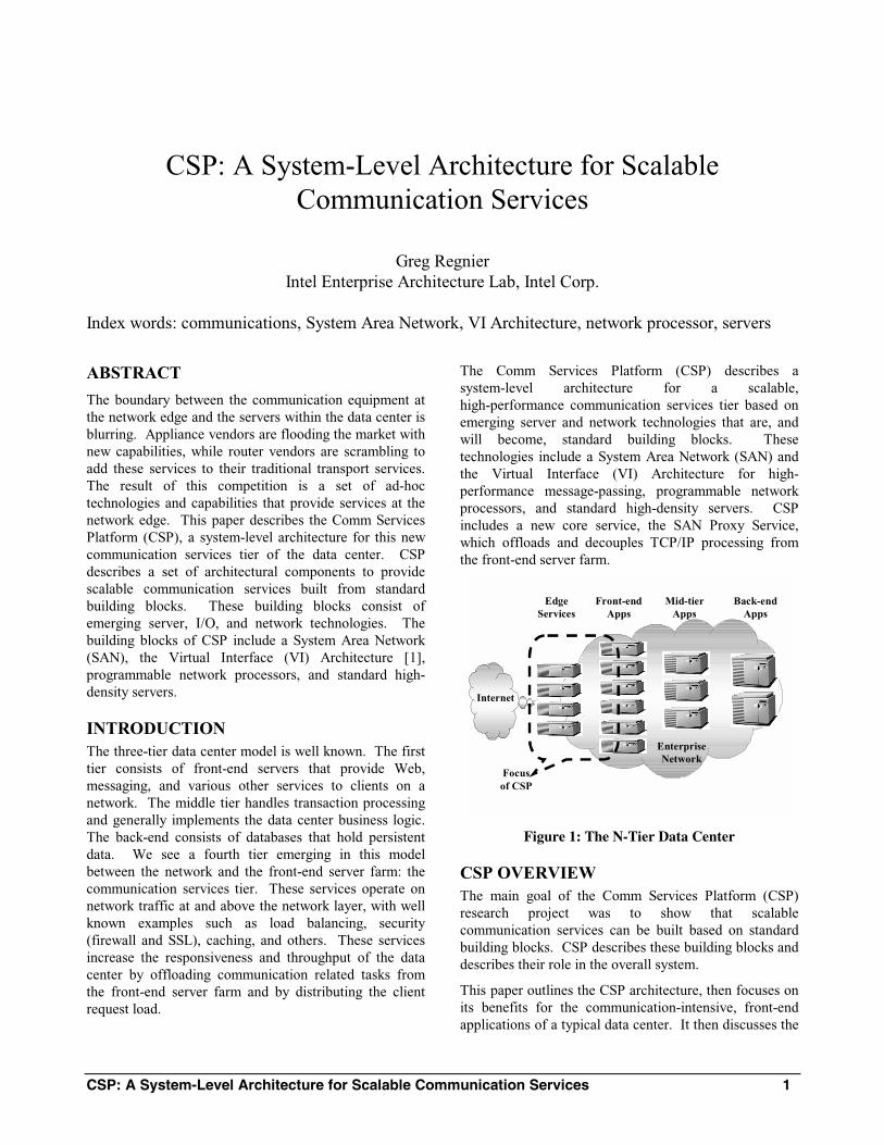
CSP: A System-Level Architecture for Scalable Communication Services 1
CSP: A System-Level Architecture for Scalable Communication Services
Greg Regnier Intel Enterprise Architecture Lab, Intel Corp.
Index words: communications, System Area Network, VI Architecture, network processor, servers
ABSTRACT
The boundary between the communication equipment at the network edge and the servers within the data center is blurring. Appliance vendors are flooding the market with new capabilities, while router vendors are scrambling to add these services to their traditional transport services. The result of this competition is a set of ad-hoc technologies and capabilities that provide services at the network edge. This paper describes the Comm Services Platform (CSP), a system-level architecture for this new communication services tier of the data center. CSP describes a set of architectural components to provide scalable communication services built from standard building blocks. These building blocks consist of emerging server, I/O, and network technologies. The building blocks of CSP include a System Area Network (SAN), the Virtual Interface (VI) Architecture [1], programmable network processors, and standard high-density servers.
INTRODUCTION The three-tier data center model is well known. The first tier consists of front-end servers that provide Web, messaging, and various other services to clients on a network. The middle tier handles transaction processing and generally implements the data center business logic. The back-end consists of databases that hold persistent data. We see a fourth tier emerging in this model between the network and the front-end server farm: the communication services tier. These services operate on network traffic at and above the network layer, with well known examples such as load balancing, security (firewall and SSL), caching, and others. These services increase the responsiveness and throughput of the data center by offloading communication related tasks from the front-end server farm and by distributing the client request load.
The Comm Services Platform (CSP) describes a system-level architecture for a scalable, high-performance communication services tier based on emerging server and network technologies that are, and will become, standard building blocks. These technologies include a System Area Network (SAN) and the Virtual Interface (VI) Architecture for high-performance message-passing, programmable network processors, and standard high-density servers. CSP includes a new core service, the SAN Proxy Service, which offloads and decouples TCP/IP processing from the front-end server farm.
EdgeServices
Front-endApps
Mid-tierApps
Back-endApps
Internet
EnterpriseNetwork
Focusof CSP
Figure 1: The N-Tier Data Center
CSP OVERVIEW The main goal of the Comm Services Platform (CSP) research project was to show that scalable communication services can be built based on standard building blocks. CSP describes these building blocks and describes their role in the overall system.
This paper outlines the CSP architecture, then focuses on its benefits for the communication-intensive, front-end applications of a typical data center. It then discusses the
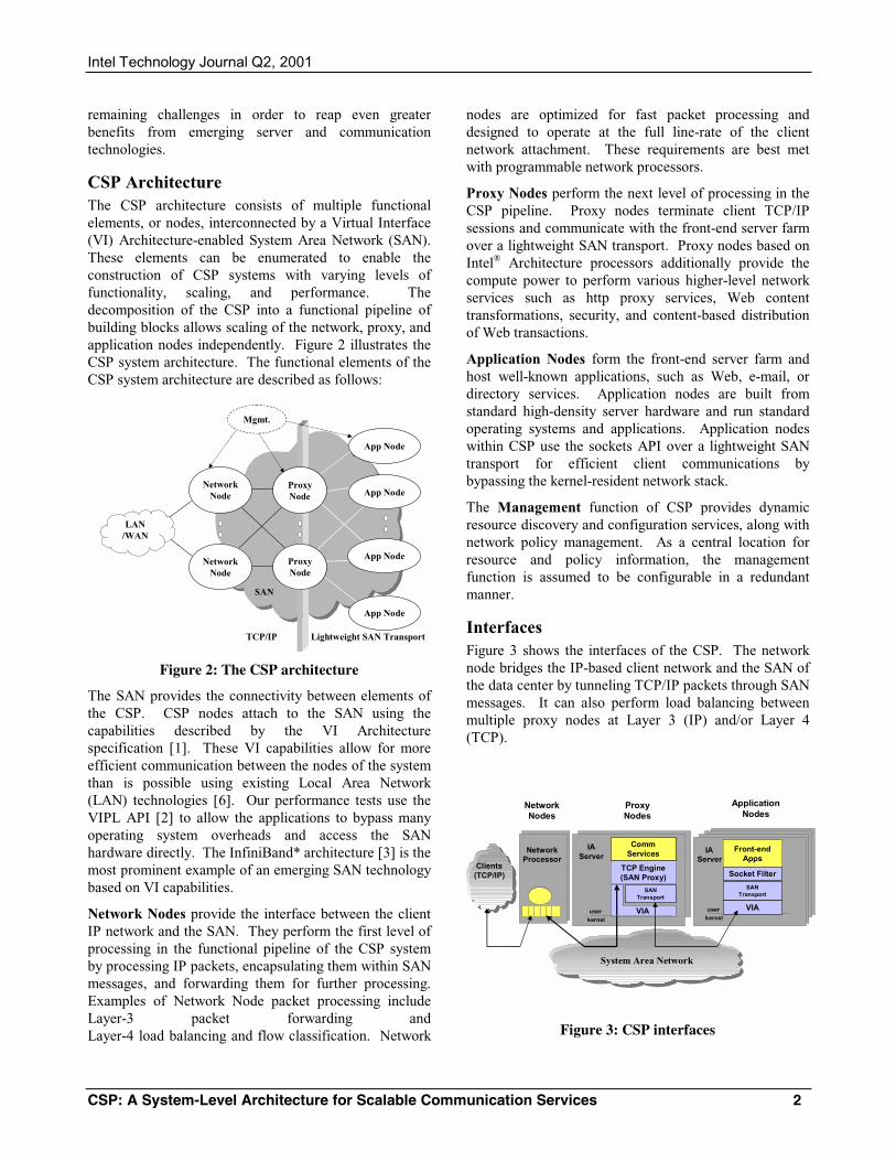
Intel Technology Journal Q2, 2001
CSP: A System-Level Architecture for Scalable Communication Services 2
remaining challenges in order to reap even greater benefits from emerging server and communication technologies.
CSP Architecture The CSP architecture consists of multiple functional elements, or nodes, interconnected by a Virtual Interface (VI) Architecture-enabled System Area Network (SAN). These elements can be enumerated to enable the construction of CSP systems with varying levels of functionality, scaling, and performance. The decomposition of the CSP into a functional pipeline of building blocks allows scaling of the network, proxy, and application nodes independently. Figure 2 illustrates the CSP system architecture. The functional elements of the CSP system architecture are described as follows:
SANSAN
Lightweight SAN TransportTCP/IP
Mgmt.
App Node
App Node
App Node
App Node
ProxyNode
ProxyNode
LAN /WAN
NetworkNode
NetworkNode
Figure 2: The CSP architecture
The SAN provides the connectivity between elements of the CSP. CSP nodes attach to the SAN using the capabilities described by the VI Architecture specification [1]. These VI capabilities allow for more efficient communication between the nodes of the system than is possible using existing Local Area Network (LAN) technologies [6]. Our performance tests use the VIPL API [2] to allow the applications to bypass many operating system overheads and access the SAN hardware directly. The InfiniBand* architecture [3] is the most prominent example of an emerging SAN technology based on VI capabilities.
Network Nodes provide the interface between the client IP network and the SAN. They perform the first level of processing in the functional pipeline of the CSP system by processing IP packets, encapsulating them within SAN messages, and forwarding them for further processing. Examples of Network Node packet processing include Layer-3 packet forwarding and Layer-4 load balancing and flow classification. Network
nodes are optimized for fast packet processing and designed to operate at the full line-rate of the client network attachment. These requirements are best met with programmable network processors.
Proxy Nodes perform the next level of processing in the CSP pipeline. Proxy nodes terminate client TCP/IP sessions and communicate with the front-end server farm over a lightweight SAN transport. Proxy nodes based on Intel® Architecture processors additionally provide the compute power to perform various higher-level network services such as http proxy services, Web content transformations, security, and content-based distribution of Web transactions.
Application Nodes form the front-end server farm and host well-known applications, such as Web, e-mail, or directory services. Application nodes are built from standard high-density server hardware and run standard operating systems and applications. Application nodes within CSP use the sockets API over a lightweight SAN transport for efficient client communications by bypassing the kernel-resident network stack.
The Management function of CSP provides dynamic resource discovery and configuration services, along with network policy management. As a central location for resource and policy information, the management function is assumed to be configurable in a redundant manner.
Interfaces Figure 3 shows the interfaces of the CSP. The network node bridges the IP-based client network and the SAN of the data center by tunneling TCP/IP packets through SAN messages. It can also perform load balancing between multiple proxy nodes at Layer 3 (IP) and/or Layer 4 (TCP).
IAServer
IAServer
userkernel
VIA
NetworkProcessor
Clients(TCP/IP)
NetworkNodes
ProxyNodes
ApplicationNodes
Socket Filter
SANTransport
SANTransport
TCP Engine (SAN Proxy)
Comm Services
System Area Network
VIA
Front-endApps
userkernel
Figure 3: CSP interfaces

Intel Technology Journal Q2, 2001
CSP: A System-Level Architecture for Scalable Communication Services 3
At the proxy nodes, the SAN tunnel allows the SAN proxy service to transfer SAN messages between itself and the network node directly from the user level using the VIPL programming interface. This allows much greater communication efficiency by bypassing the operating system overheads associated with kernel-based network stacks. It terminates the TCP/IP sessions at the proxy node and converts them to a higher level SAN transport protocol that requires less control traffic; state management is thus more efficient for the front-end application nodes. Figure 4 shows the flow of packets for an HTTP/1.0 transaction on the CSP with TCP/IP termination and protocol translation at the proxy node, illustrating the simplified control traffic at the application node.
Client Network Node Proxy Node Application Node
TCPIP Protocol SAN Protocol
SAN Tunnel
SYN
SYN+ACK
ACK
HTTP REQ
ACK
DATAACK
ACKs
DATA
DATAs
FIN
FIN+ACKACK
CONN REQ + HTTP REQ
CONN ACCEPT + DATA
DATA
DATA
DATA + CLOSE CONN
HTTP Access
Figure 4: Example HTTP Transaction on CSP
The proxy node is the logical place for higher level communication services to exist since the SAN proxy service has each packet at the user level, and can easily pass the packets on to higher level services efficiently. Examples of these higher level services would be caching, security, and transcoding.
Given the TCP/IP termination at the proxy nodes, the application nodes can now process client requests over a more efficient communication stack. A lightweight SAN transport protocol built on top of VIPL provides basic end-to-end flow control between the proxy nodes and the application nodes. Another thin layer of software, the “socket filter” maps the legacy sockets interface to the SAN transport. This stack runs at the user level in the performance critical path.
CSP PROTOTYPE A combination of system prototyping and simulation was used for evaluation of the Comm Services Platform (CSP) performance, scalability, and for architectural validation. Prototyping with off-the-shelf hardware and software components was focused on dealing with the real-world problems of implementing a CSP system with existing technology.
For the network node, we used an Intel® IXP-1200 [4] network processor platform. We developed the microcode that tunnels client Local Area Network (LAN) traffic into the System Area Network (SAN). The prototype also performed simple Layer-4 load balancing to distribute the traffic to multiple proxy nodes.
For the application and proxy nodes of the CSP prototype, we used standard rack-mounted servers, each with a single 800 Megahertz Pentium III processor and a 64-bit, 33 Megahertz PCI IO bus. These servers ran the Linux∗ Version 2.2 kernel.
For the SAN network interface, we used a proprietary SAN (cLAN*) from Giganet Inc. that natively implements the Virtual Interface (VI) Architecture with a maximum hardware transfer rate of 1.25 Gigabits per second full duplex. For the LAN measurements, we used off-the-shelf Gigabit Ethernet PCI network adapters.
CSP APPLICATION RESULTS Given that a major focus of the Comm Services Platform (CSP) is to provide a more efficient communication infrastructure for front-end server applications, we focus here on the performance analysis of the application node. A more complete analysis of the complete CSP system is described in our paper to be presented at the 2001 Usenix Symposium on Internet Technology and Systems [5].
Software overhead in the operating system network stacks, specifically sockets and TCP/IP, has been identified as a major bottleneck in server communications performance. Even after factoring in increases in server CPU speeds, and incrementally offloading portions of the stack onto network interface hardware, communication demands are outstripping the ability of servers to perform the required protocol processing. To overcome these inefficiencies, in particular for the communication-intensive front-end applications, CSP exploits the capabilities of a Virtual Interface (VI)-enabled System Area Network (SAN) fabric as the system interconnect.
∗ Other brands and names may be claimed as the property of others.
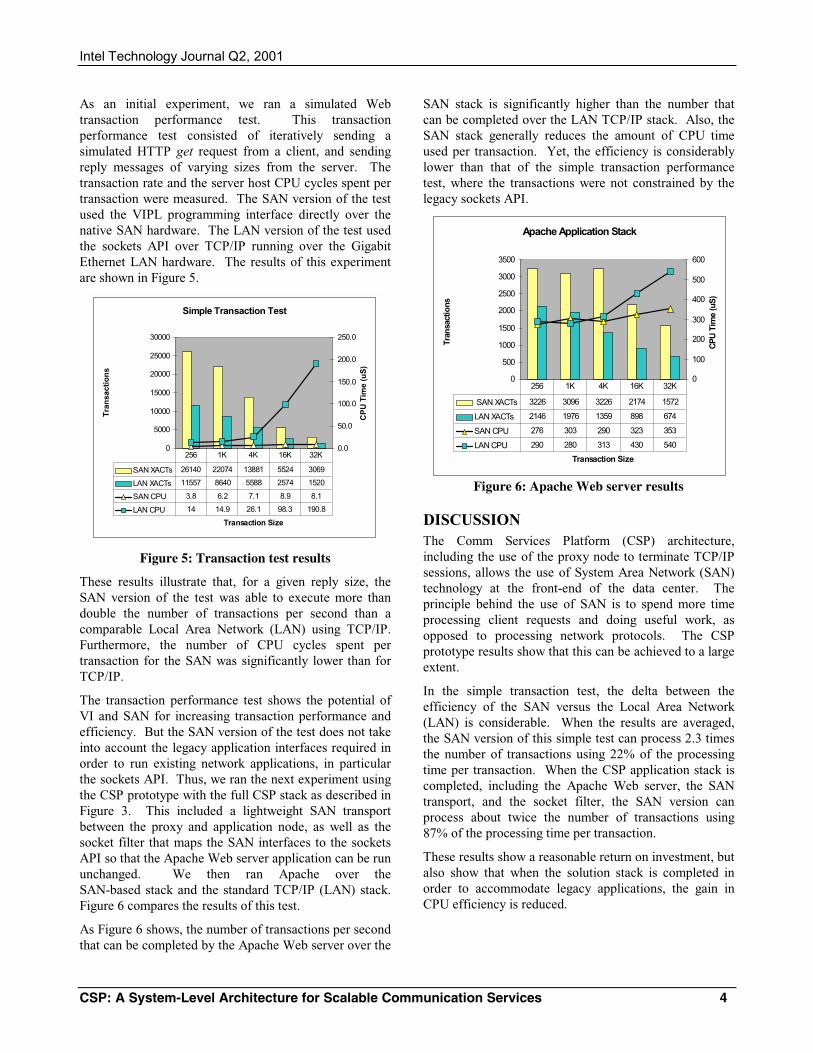
Intel Technology Journal Q2, 2001
CSP: A System-Level Architecture for Scalable Communication Services 4
As an initial experiment, we ran a simulated Web transaction performance test. This transaction performance test consisted of iteratively sending a simulated HTTP get request from a client, and sending reply messages of varying sizes from the server. The transaction rate and the server host CPU cycles spent per transaction were measured. The SAN version of the test used the VIPL programming interface directly over the native SAN hardware. The LAN version of the test used the sockets API over TCP/IP running over the Gigabit Ethernet LAN hardware. The results of this experiment are shown in Figure 5.
Simple Transaction Test
0
5000
10000
15000
20000
25000
30000
Transaction Size
Tra
nsa
ctio
ns
0.0
50.0
100.0
150.0
200.0
250.0
CP
U T
ime
(uS
)
SAN XACTs 26140 22074 13881 5524 3069
LAN XACTs 11557 8640 5588 2574 1520
SAN CPU 3.8 6.2 7.1 8.9 8.1
LAN CPU 14 14.9 26.1 98.3 190.8
256 1K 4K 16K 32K
Figure 5: Transaction test results
These results illustrate that, for a given reply size, the SAN version of the test was able to execute more than double the number of transactions per second than a comparable Local Area Network (LAN) using TCP/IP. Furthermore, the number of CPU cycles spent per transaction for the SAN was significantly lower than for TCP/IP.
The transaction performance test shows the potential of VI and SAN for increasing transaction performance and efficiency. But the SAN version of the test does not take into account the legacy application interfaces required in order to run existing network applications, in particular the sockets API. Thus, we ran the next experiment using the CSP prototype with the full CSP stack as described in Figure 3. This included a lightweight SAN transport between the proxy and application node, as well as the socket filter that maps the SAN interfaces to the sockets API so that the Apache Web server application can be run unchanged. We then ran Apache over the SAN-based stack and the standard TCP/IP (LAN) stack. Figure 6 compares the results of this test.
As Figure 6 shows, the number of transactions per second that can be completed by the Apache Web server over the
SAN stack is significantly higher than the number that can be completed over the LAN TCP/IP stack. Also, the SAN stack generally reduces the amount of CPU time used per transaction. Yet, the efficiency is considerably lower than that of the simple transaction performance test, where the transactions were not constrained by the legacy sockets API.
Apache Application Stack
0
500
1000
1500
2000
2500
3000
3500
Transaction Size
Tran
sact
ions
0
100
200
300
400
500
600
CP
U T
ime
(uS
)
SAN XACTs 3226 3096 3226 2174 1572
LAN XACTs 2146 1976 1359 898 674
SAN CPU 276 303 290 323 353
LAN CPU 290 280 313 430 540
256 1K 4K 16K 32K
Figure 6: Apache Web server results
DISCUSSION The Comm Services Platform (CSP) architecture, including the use of the proxy node to terminate TCP/IP sessions, allows the use of System Area Network (SAN) technology at the front-end of the data center. The principle behind the use of SAN is to spend more time processing client requests and doing useful work, as opposed to processing network protocols. The CSP prototype results show that this can be achieved to a large extent.
In the simple transaction test, the delta between the efficiency of the SAN versus the Local Area Network (LAN) is considerable. When the results are averaged, the SAN version of this simple test can process 2.3 times the number of transactions using 22% of the processing time per transaction. When the CSP application stack is completed, including the Apache Web server, the SAN transport, and the socket filter, the SAN version can process about twice the number of transactions using 87% of the processing time per transaction.
These results show a reasonable return on investment, but also show that when the solution stack is completed in order to accommodate legacy applications, the gain in CPU efficiency is reduced.
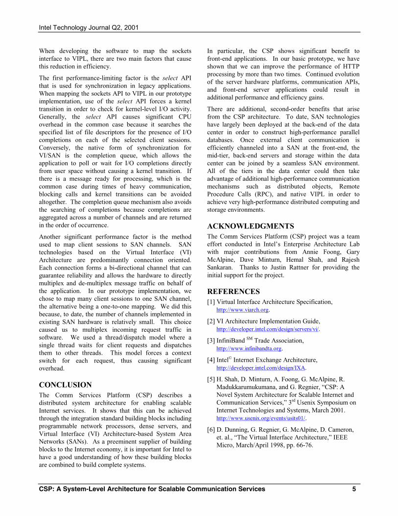
Intel Technology Journal Q2, 2001
CSP: A System-Level Architecture for Scalable Communication Services 5
When developing the software to map the sockets interface to VIPL, there are two main factors that cause this reduction in efficiency.
The first performance-limiting factor is the select API that is used for synchronization in legacy applications. When mapping the sockets API to VIPL in our prototype implementation, use of the select API forces a kernel transition in order to check for kernel-level I/O activity. Generally, the select API causes significant CPU overhead in the common case because it searches the specified list of file descriptors for the presence of I/O completions on each of the selected client sessions. Conversely, the native form of synchronization for VI/SAN is the completion queue, which allows the application to poll or wait for I/O completions directly from user space without causing a kernel transition. If there is a message ready for processing, which is the common case during times of heavy communication, blocking calls and kernel transitions can be avoided altogether. The completion queue mechanism also avoids the searching of completions because completions are aggregated across a number of channels and are returned in the order of occurrence.
Another significant performance factor is the method used to map client sessions to SAN channels. SAN technologies based on the Virtual Interface (VI) Architecture are predominantly connection oriented. Each connection forms a bi-directional channel that can guarantee reliability and allows the hardware to directly multiplex and de-multiplex message traffic on behalf of the application. In our prototype implementation, we chose to map many client sessions to one SAN channel, the alternative being a one-to-one mapping. We did this because, to date, the number of channels implemented in existing SAN hardware is relatively small. This choice caused us to multiplex incoming request traffic in software. We used a thread/dispatch model where a single thread waits for client requests and dispatches them to other threads. This model forces a context switch for each request, thus causing significant overhead.
CONCLUSION The Comm Services Platform (CSP) describes a distributed system architecture for enabling scalable Internet services. It shows that this can be achieved through the integration standard building blocks including programmable network processors, dense servers, and Virtual Interface (VI) Architecture-based System Area Networks (SANs). As a preeminent supplier of building blocks to the Internet economy, it is important for Intel to have a good understanding of how these building blocks are combined to build complete systems.
In particular, the CSP shows significant benefit to front-end applications. In our basic prototype, we have shown that we can improve the performance of HTTP processing by more than two times. Continued evolution of the server hardware platforms, communication APIs, and front-end server applications could result in additional performance and efficiency gains.
There are additional, second-order benefits that arise from the CSP architecture. To date, SAN technologies have largely been deployed at the back-end of the data center in order to construct high-performance parallel databases. Once external client communication is efficiently channeled into a SAN at the front-end, the mid-tier, back-end servers and storage within the data center can be joined by a seamless SAN environment. All of the tiers in the data center could then take advantage of additional high-performance communication mechanisms such as distributed objects, Remote Procedure Calls (RPC), and native VIPL in order to achieve very high-performance distributed computing and storage environments.
ACKNOWLEDGMENTS The Comm Services Platform (CSP) project was a team effort conducted in Intel’s Enterprise Architecture Lab with major contributions from Annie Foong, Gary McAlpine, Dave Minturn, Hemal Shah, and Rajesh Sankaran. Thanks to Justin Rattner for providing the initial support for the project.
REFERENCES [1] Virtual Interface Architecture Specification,
http://www.viarch.org.
[2] VI Architecture Implementation Guide, http://developer.intel.com/design/servers/vi/.
[3] InfiniBand SM Trade Association, http://www.infinibandta.org.
[4] Intel© Internet Exchange Architecture, http://developer.intel.com/design/IXA.
[5] H. Shah, D. Minturn, A. Foong, G. McAlpine, R. Madukkarumukumana, and G. Regnier, “CSP: A Novel System Architecture for Scalable Internet and Communication Services,” 3rd Usenix Symposium on Internet Technologies and Systems, March 2001. http://www.usenix.org/events/usits01/.
[6] D. Dunning, G. Regnier, G. McAlpine, D. Cameron, et. al., “The Virtual Interface Architecture,” IEEE Micro, March/April 1998, pp. 66-76.
Intel Technology Journal Q2, 2001
CSP: A System-Level Architecture for Scalable Communication Services 6
AUTHOR’S BIOGRAPHY Greg Regnier is a Principal Engineer and manager of the I/O and Cluster Architecture group in Intel’s Enterprise Architecture Lab. Greg’s experience and interests include high-performance message passing, networking, and distributed computing. Greg has a BSCS (’79) from Saint Cloud State University in Minnesota. His e-mail address is [email protected]
Copyright © Intel Corporation 2001. This publication was downloaded from http://developer.intel.com/.
Legal notices at http://developer.intel.com/sites/developer/tradmarx.htm.