Embed Size (px)
Citation preview
25 Amp, 3 Stage Switchmode
INTELLI-CHARGE
DC/SOLAR BATTERY CHARGER
P/No. IDC25
2
WARNINGS• Explosive gases may escape from the battery during charging.
Prevent flames and sparks and provide adequate ventilation.
• Before charging, read the instructions.
• FOR CHARGING 12 VOLT LEAD ACID BATTERIES ONLY.
• Do not attempt to charge non-rechargeable batteries.
• Never charge a frozen battery.
• Corrosive substances may escape from the battery during charging and damage delicate surfaces. Store and charge in a suitable area.
• This appliance is not intended for use by young children or infirm persons unless they have been adequately supervised by a responsible person to ensure that they can use the appliance safely.
• Young children should be supervised to ensure that they do not play with the appliance.
• Fit fuses as close to the batteries as possible to protect the cable in case of short circuit.
FEATURES The IDC25 DC-DC charger is purposely designed for charging auxiliary batteries.
It includes all the features needed to maintain the auxiliary battery to its optimum condition and to prolong the battery life.
SWITCHMODE TECHNOLOGY The IDC25 converts your vehicle’s 12VDC/24VDC alternator power to the voltage
level allowing your batteries to be fully charged, prolonging battery life and reliability. With the latest synchronous switching technology, efficiency of IDC25 exceeds 94% at typical full load condition.
DUAL INPUT OPERATION Allows two energy sources to power the IDC25 simultaneously. Solar input takes
precedence if solar and alternator inputs are present. When solar input cannot provide enough energy to the load, the IDC25 will draw power from solar and alternator simultaneously.
SOLAR MPPT The IDC25 utilises sophisticated MPPT (Maximum Power Point Tracking) solar
regulator technology. MPPT maximises the power generated from the solar panels to the auxiliary battery.
3
SUPERIOR 3 STAGE CHARGING Using high speed microcontroller and proprietary charging algorithm, the IDC25
delivers a sophisticated 3 stage charging process resulting in a faster and more powerful charge, ideal for deep cycle batteries. The first stage, bulk (constant current), charges the battery faster while the second stage, absorption (constant voltage), ensures the battery is thoroughly charged. The final stage, float, maintains the battery at a safe voltage allowing it to be maintained and ready for use indefinitely.
MULTI-CHEMISTRY SUPPORT The IDC25 supports GEL, AGM, WET and CALCIUM batteries. If the calcium battery
mode is selected, periodic equalisation will be provided to the calcium battery for removing acid stratification.
IGNITION CONNECTION The IDC25 can be wired to the vehicle’s ignition allowing it to operate only when
the ignition is turned on. The ignition connection also activates the lower input voltage operation to suit vehicles with smart (variable voltage) alternators.
TEMPERATURE COMPENSATION The IDC25 is supplied with a 2 metre temperature sensor. The sensor monitors the
battery temperature and adjusts (compensates) the charger’s output to prevent overcharging. This is ideal for batteries used in warmer climates or environments.
REMOTE CHARGER STATUS INDICATION A pink wire is provided for driving an external panel mount LED indicator (Eg Narva
P/No. 62090BL) to show the status of the charger. It shows whether the auxiliary battery is on charge (Solid Colour) or the charger is in a fault condition (Flashing).
PROTECTIVE FEATURES Spark-Free Protection The IDC25 will not start charging the battery (no output) unless the load is securely
connected. It prevents the output leads from sparking due to accidental short circuit making the charger safer to use around batteries.
Reverse Connection Protection Reverse connection on input and output terminals does not damage IDC25 internal
circuit. The IDC25 detects reverse connection condition and indicates whether input or output connection is reversed.
Over and Under Voltage Protection The charger will automatically shut down if there is an over voltage or under
voltage problem.
Over Temperature Protection The charger will lower its output current if the temperature of the unit begins to
overheat.
4
SPECIFICATIONS
Operating Conditions
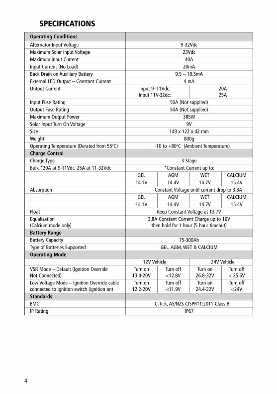
Alternator Input Voltage 9-32Vdc Maximum Solar Input Voltage 23Vdc Maximum Input Current 40A Input Current (No Load) 20mA Back Drain on Auxiliary Battery 9.5 – 10.5mA External LED Output – Constant Current 4 mA Output Current Input 9–11Vdc: 20A Input 11V-32dc: 25A Input Fuse Rating 50A (Not supplied) Output Fuse Rating 50A (Not supplied) Maximum Output Power 385W Solar Input Turn On Voltage 9V Size 149 x 122 x 42 mm Weight 800g Operating Temperature (Derated from 55oC) -10 to +80oC (Ambient Temperature) Charge Control Charge Type 3 Stage Bulk *20A at 9-11Vdc, 25A at 11-32Vdc *Constant Current up to: GEL AGM WET CALCIUM 14.1V 14.4V 14.7V 15.4V Absorption Constant Voltage until current drop to 3.8A GEL AGM WET CALCIUM 14.1V 14.4V 14.7V 15.4V Float Keep Constant Voltage at 13.7V Equalisation 3.8A Constant Current Charge up to 16V (Calcium mode only) then hold for 1 hour (5 hour timeout) Battery Range Battery Capacity 75-300Ah Type of Batteries Supported GEL, AGM, WET & CALCIUM Operating Mode 12V Vehicle 24V Vehicle VSR Mode – Default (Ignition Override Turn on Turn off Turn on Turn off Not Connected) 13.4-20V <12.8V 26.8-32V < 25.6V Low Voltage Mode – Ignition Override cable Turn on Turn off Turn on Turn off connected to ignition switch (ignition on) 12.2-20V <11.9V 24.4-32V <24V Standards EMC C-Tick, AS/NZS CISPR11:2011 Class B IP Rating IP67
5
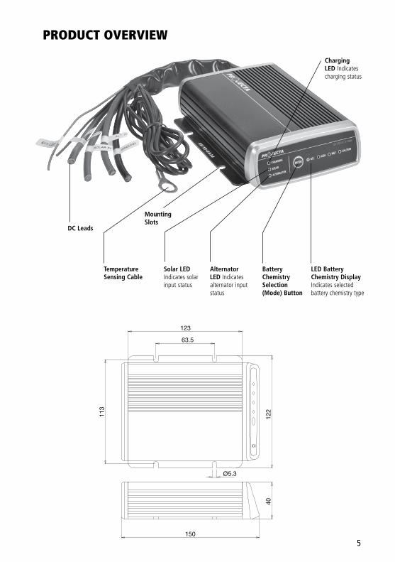
PRODUCT OVERVIEW
Mounting Slots
Charging LED Indicates charging status
Solar LEDIndicates solar input status
Alternator LED Indicates alternator input status
LED Battery Chemistry DisplayIndicates selected battery chemistry type
DC Leads
Temperature Sensing Cable
Battery Chemistry Selection (Mode) Button
Ø5.3
123
122
63.5
40
113
150
6
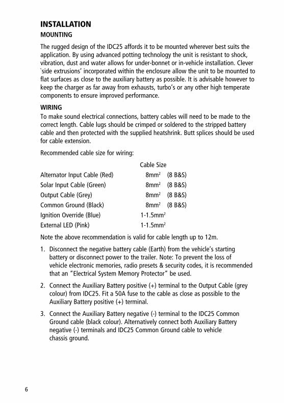
INSTALLATION MOUNTING
The rugged design of the IDC25 affords it to be mounted wherever best suits the application. By using advanced potting technology the unit is resistant to shock, vibration, dust and water allows for under-bonnet or in-vehicle installation. Clever `side extrusions’ incorporated within the enclosure allow the unit to be mounted to flat surfaces as close to the auxiliary battery as possible. It is advisable however to keep the charger as far away from exhausts, turbo’s or any other high temperate components to ensure improved performance.
WIRING To make sound electrical connections, battery cables will need to be made to the
correct length. Cable lugs should be crimped or soldered to the stripped battery cable and then protected with the supplied heatshrink. Butt splices should be used for cable extension.
Recommended cable size for wiring:
Cable Size
Alternator Input Cable (Red) 8mm2 (8 B&S)
Solar Input Cable (Green) 8mm2 (8 B&S)
Output Cable (Grey) 8mm2 (8 B&S)
Common Ground (Black) 8mm2 (8 B&S)
Ignition Override (Blue) 1-1.5mm2
External LED (Pink) 1-1.5mm2
Note the above recommendation is valid for cable length up to 12m.
1. Disconnect the negative battery cable (Earth) from the vehicle’s starting battery or disconnect power to the trailer. Note: To prevent the loss of vehicle electronic memories, radio presets & security codes, it is recommended that an “Electrical System Memory Protector” be used.
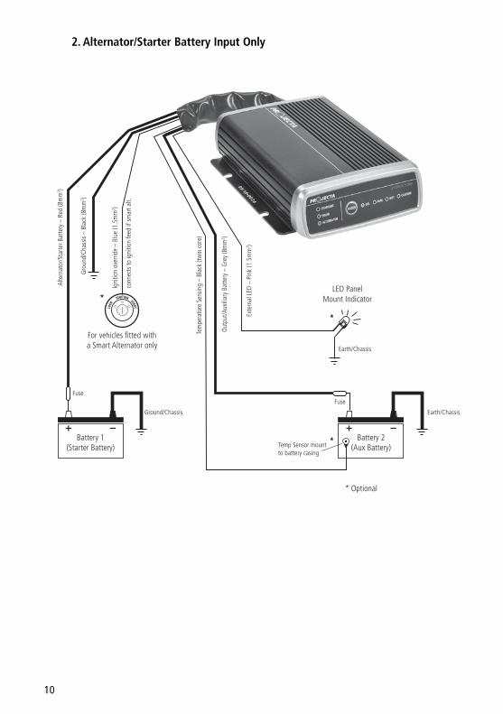
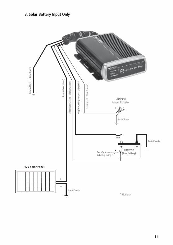
2. Connect the Auxiliary Battery positive (+) terminal to the Output Cable (grey colour) from IDC25. Fit a 50A fuse to the cable as close as possible to the Auxiliary Battery positive (+) terminal.
3. Connect the Auxiliary Battery negative (-) terminal to the IDC25 Common Ground cable (black colour). Alternatively connect both Auxiliary Battery negative (-) terminals and IDC25 Common Ground cable to vehicle chassis ground.
7
4. Connect the Starter Battery positive (+) terminal to the IDC25 Alternator Input cable (red colour). Fit a 50A fuse to the cable as close as possible to the Starter Battery positive (+) terminal.
5. If your vehicle has fixed voltage or temperature compensating alternator installed, leave the Ignition Override cable (blue colour) open.
If your vehicle has smart (variable voltage) alternator installed, the Ignition Override cable must be connected to the vehicle’s ignition. The IDC25 will only operate when the vehicle’s ignition is turned on.
However, if solar panels are connected to IDC25, the IDC25 will operate and only draw power from solar panels (assuming vehicle’s ignition is turned off). Fit a 1-2A fuse to the cable as close as possible to the vehicle’s ignition. Consult the vehicle manufacturer for type of alternator installed in your vehicle.
6. When 12V solar panels are present, connect the solar panel positive terminal (+) to the IDC25 Solar Input cable (green colour). Fit a 50A fuse to the cable as close as possible to the Solar Panel positive (+) terminal.
Then, connect the Solar Panel negative (-) terminal to the IDC25 Common Ground cable (black colour). Alternatively connect both Solar Panel negative (-) terminals and IDC25 Common Ground cable to vehicle chassis ground.
7. The external LED wire provides 4mA constant current output. It can power an LED panel mount indicator with or without an internal resistor.
Leave External LED cable open if you do not need the external LED indication. If external LED indication is required, connect the positive (+) terminal of a LED Indicator to the External LED cable.
Then, connect the negative terminal of LED Indicator to the vehicle chassis ground.
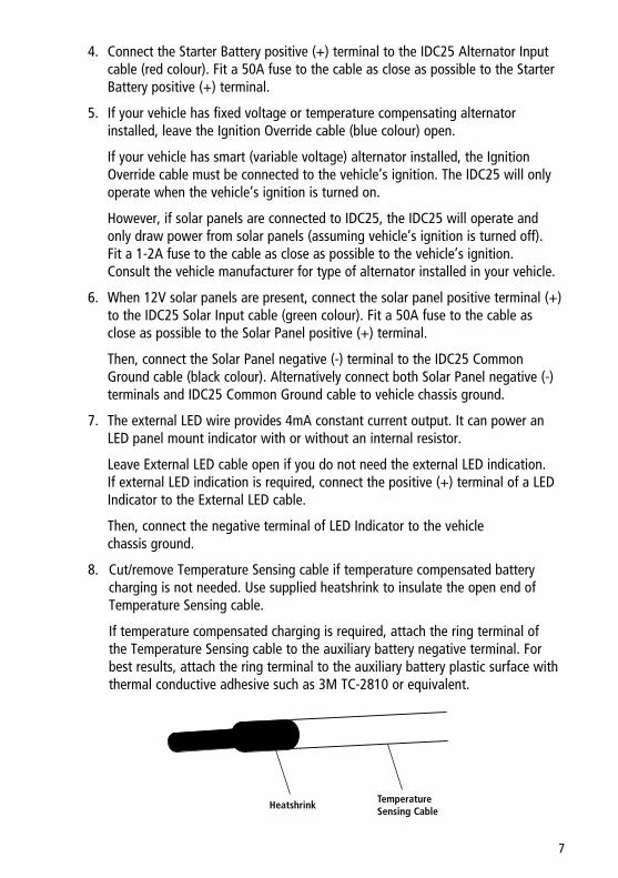
8. Cut/remove Temperature Sensing cable if temperature compensated battery charging is not needed. Use supplied heatshrink to insulate the open end of Temperature Sensing cable.
If temperature compensated charging is required, attach the ring terminal of the Temperature Sensing cable to the auxiliary battery negative terminal. For best results, attach the ring terminal to the auxiliary battery plastic surface with thermal conductive adhesive such as 3M TC-2810 or equivalent.
Temperature Sensing Cable
Heatshrink
8
SELECTION OF AUXILIARY BATTERY TYPE Press the Mode button on the front panel until all Battery Chemistry LEDs are
flashing. There are 4 battery chemistries available: Gel, AGM, Wet and Calcium. Keep pressing the button momentarily until the Battery Chemistry LED you want is flashing. After you release the button, your selection is entered and saved. Your selection will be restored automatically even after the IDC25 is fully disconnected and reconnected. The default Battery Chemistry is AGM.
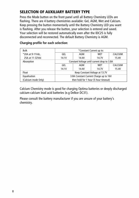
Charging profile for each selection:
Bulk *Constant Current up to: *20A at 9-11Vdc, GEL AGM WET CALCIUM 25A at 11-32Vdc 14.1V 14.4V 14.7V 15.4V Absorption Constant Voltage until current drop to 3.8A GEL AGM WET CALCIUM 14.1V 14.4V 14.7V 15.4V Float Keep Constant Voltage at 13.7V Equalisation 3.8A Constant Current Charge up to 16V (Calcium mode Only) then hold for 1 hour (5 hour timeout)
Calcium Chemistry mode is good for charging Optima batteries or deeply discharged calcium-calcium lead acid batteries (e.g Delkor DC31).
Please consult the battery manufacturer if you are unsure of your battery’s chemistry.
9
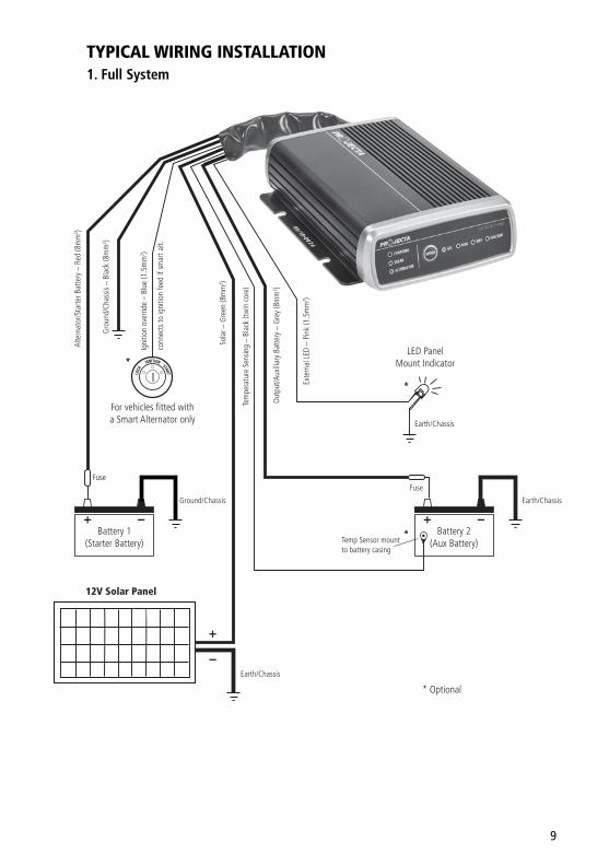
TYPICAL WIRING INSTALLATION 1. Full System
12V Solar Panel
* Optional
*
*
*
For vehicles fitted witha Smart Alternator only
LED PanelMount Indicator
Earth/Chassis
Alte
rnat
or/S
tarte
r Bat
tery
– R
ed (8
mm
2 )
Gro
und/
Chas
sis –
Bla
ck (8
mm
2 )
Igni
tion
over
ride
– Bl
ue (1
.5m
m2 )
Exte
rnal
LED
– P
ink
(1.5
mm
2 )
Sola
r – G
reen
(8m
m2 )
Out
put/A
uxili
ary
Batte
ry –
Gre
y (8
mm
2 )
Tem
pera
ture
Sen
sing
– Bl
ack
(twin
cor
e)
Temp Sensor mountto battery casing
conn
ects
to ig
nitio
n fe
ed if
sm
art a
lt.
Earth/Chassis
Earth/ChassisGround/Chassis
FuseFuse
Battery 2(Aux Battery)
Battery 1(Starter Battery)
10
2. Alternator/Starter Battery Input Only
For vehicles fitted witha Smart Alternator only
LED PanelMount Indicator
Earth/Chassis
Alte
rnat
or/S
tarte
r Bat
tery
– R
ed (8
mm
2 )
Gro
und/
Chas
sis –
Bla
ck (8
mm
2 )
Igni
tion
over
ride
– Bl
ue (1
.5m
m2 )
Exte
rnal
LED
– P
ink
(1.5
mm
2 )
Out
put/A
uxili
ary
Batte
ry –
Gre
y (8
mm
2 )
Tem
pera
ture
Sen
sing
– Bl
ack
(twin
cor
e)
Temp Sensor mountto battery casing
conn
ects
to ig
nitio
n fe
ed if
sm
art a
lt.
Earth/ChassisGround/Chassis
FuseFuse
Battery 2(Aux Battery)
Battery 1(Starter Battery)
* Optional
*
*
*
11
3. Solar Battery Input Only
12V Solar Panel
LED PanelMount Indicator
Earth/Chassis
Gro
und/
Chas
sis –
Bla
ck (8
mm
2 )
Exte
rnal
LED
– P
ink
(1.5
mm
2 )
Sola
r – G
reen
(8m
m2 )
Out
put/A
uxili
ary
Batte
ry –
Gre
y (8
mm
2 )
Tem
pera
ture
Sen
sing
– Bl
ack
(twin
cor
e)
Temp Sensor mountto battery casing
Earth/Chassis
Earth/Chassis
Fuse
Battery 2(Aux Battery)
* Optional
*
*
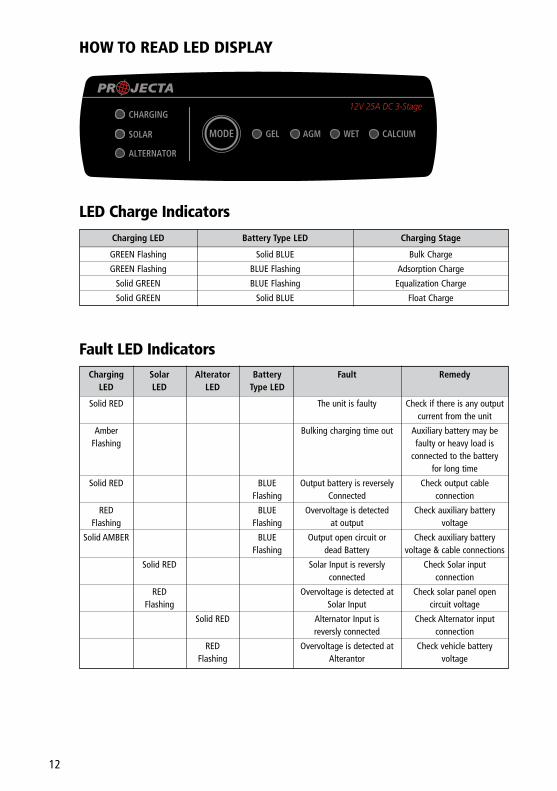
HOW TO READ LED DISPLAY
LED Charge Indicators
Fault LED Indicators
Charging LED Battery Type LED Charging Stage
GREEN Flashing Solid BLUE Bulk Charge
GREEN Flashing BLUE Flashing Adsorption Charge
Solid GREEN BLUE Flashing Equalization Charge
Solid GREEN Solid BLUE Float Charge
Charging Solar Alterator Battery Fault Remedy LED LED LED Type LED
Solid RED The unit is faulty Check if there is any output current from the unit
Amber Bulking charging time out Auxiliary battery may be Flashing faulty or heavy load is connected to the battery for long time
Solid RED BLUE Output battery is reversely Check output cable Flashing Connected connection
RED BLUE Overvoltage is detected Check auxiliary battery Flashing Flashing at output voltage
Solid AMBER BLUE Output open circuit or Check auxiliary battery Flashing dead Battery voltage & cable connections
Solid RED Solar Input is reversly Check Solar input connected connection
RED Overvoltage is detected at Check solar panel open Flashing Solar Input circuit voltage
Solid RED Alternator Input is Check Alternator input reversly connected connection
RED Overvoltage is detected at Check vehicle battery Flashing Alterantor voltage
GEL AGM WET CALCIUMMODE
12V 25A DC 3-Stage
ALTERNATOR
CHARGING
SOLAR
12
13
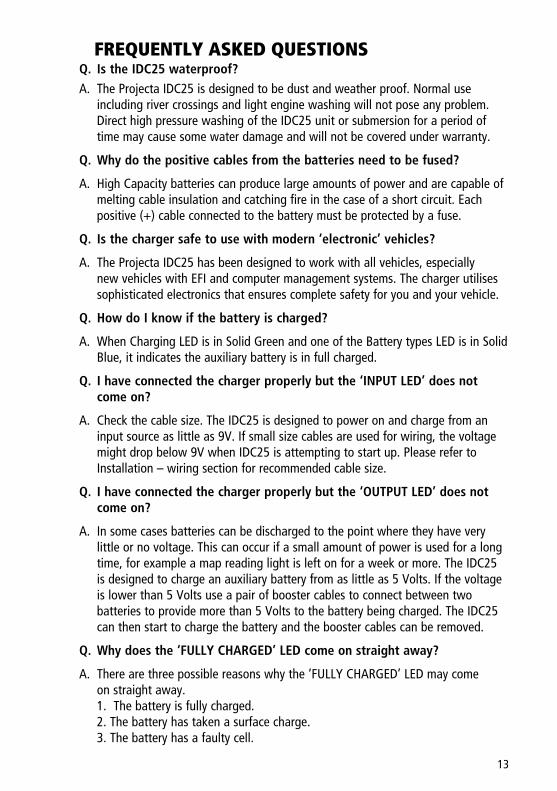
FREQUENTLY ASKED QUESTIONS Q. Is the IDC25 waterproof? A. The Projecta IDC25 is designed to be dust and weather proof. Normal use
including river crossings and light engine washing will not pose any problem. Direct high pressure washing of the IDC25 unit or submersion for a period of time may cause some water damage and will not be covered under warranty.
Q. Why do the positive cables from the batteries need to be fused?
A. High Capacity batteries can produce large amounts of power and are capable of melting cable insulation and catching fire in the case of a short circuit. Each positive (+) cable connected to the battery must be protected by a fuse.
Q. Is the charger safe to use with modern ‘electronic’ vehicles?
A. The Projecta IDC25 has been designed to work with all vehicles, especially new vehicles with EFI and computer management systems. The charger utilises sophisticated electronics that ensures complete safety for you and your vehicle.
Q. How do I know if the battery is charged?
A. When Charging LED is in Solid Green and one of the Battery types LED is in Solid Blue, it indicates the auxiliary battery is in full charged.
Q. I have connected the charger properly but the ‘INPUT LED’ does not come on?
A. Check the cable size. The IDC25 is designed to power on and charge from an input source as little as 9V. If small size cables are used for wiring, the voltage might drop below 9V when IDC25 is attempting to start up. Please refer to Installation – wiring section for recommended cable size.
Q. I have connected the charger properly but the ‘OUTPUT LED’ does not come on?
A. In some cases batteries can be discharged to the point where they have very little or no voltage. This can occur if a small amount of power is used for a long time, for example a map reading light is left on for a week or more. The IDC25 is designed to charge an auxiliary battery from as little as 5 Volts. If the voltage is lower than 5 Volts use a pair of booster cables to connect between two batteries to provide more than 5 Volts to the battery being charged. The IDC25 can then start to charge the battery and the booster cables can be removed.
Q. Why does the ‘FULLY CHARGED’ LED come on straight away?
A. There are three possible reasons why the ‘FULLY CHARGED’ LED may come on straight away.
1. The battery is fully charged. 2. The battery has taken a surface charge. 3. The battery has a faulty cell.
14
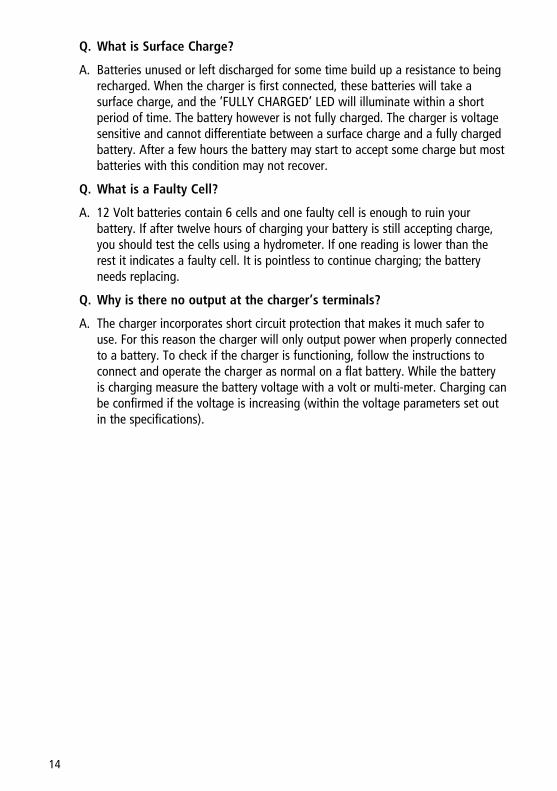
Q. What is Surface Charge?
A. Batteries unused or left discharged for some time build up a resistance to being recharged. When the charger is first connected, these batteries will take a surface charge, and the ‘FULLY CHARGED’ LED will illuminate within a short period of time. The battery however is not fully charged. The charger is voltage sensitive and cannot differentiate between a surface charge and a fully charged battery. After a few hours the battery may start to accept some charge but most batteries with this condition may not recover.
Q. What is a Faulty Cell?
A. 12 Volt batteries contain 6 cells and one faulty cell is enough to ruin your battery. If after twelve hours of charging your battery is still accepting charge, you should test the cells using a hydrometer. If one reading is lower than the rest it indicates a faulty cell. It is pointless to continue charging; the battery needs replacing.
Q. Why is there no output at the charger’s terminals?
A. The charger incorporates short circuit protection that makes it much safer to use. For this reason the charger will only output power when properly connected to a battery. To check if the charger is functioning, follow the instructions to connect and operate the charger as normal on a flat battery. While the battery is charging measure the battery voltage with a volt or multi-meter. Charging can be confirmed if the voltage is increasing (within the voltage parameters set out in the specifications).

15
NOTES
Distributed by
AUSTRALIABrown & Watson International Pty LtdKnoxfield, Victoria 3180Telephone (03) 9730 6000Facsimile (03) 9730 6050National Toll Free 1800 113 443
NEW ZEALANDNarva New Zealand Ltd22–24 Olive RoadPO Box 12556 PenroseAuckland, New ZealandTelephone (09) 525 4575Facsimile (09) 579 1192
IS296Issue 1 18.8.15
WARRANTY STATEMENTApplicable only to product sold in AustraliaBrown & Watson International Pty Ltd of 1500 Ferntree Gully Road, Knoxfield, Vic., telephone (03) 9730 6000, fax (03) 9730 6050, warrants that all products described in its current catalogue (save and except for all bulbs and lenses whether made of glass or some other substance) will under normal use and service be free of failures in material and workmanship for a period of one (1) year (unless this period has been extended as indicated elsewhere) from the date of the original purchase by the consumer as marked on the invoice. This warranty does not cover ordinary wear and tear, abuse, alteration of products or damage caused by the consumer.
To make a warranty claim the consumer must deliver the product at their cost to the original place of purchase or to any other place which may be nominated by either BWI or the retailer from where the product was bought in order that a warranty assessment may be performed. The consumer must also deliver the original invoice evidencing the date and place of purchase together with an explanation in writing as to the nature of the claim.
In the event that the claim is determined to be for a minor failure of the product then BWI reserves the right to repair or replace it at its discretion. In the event that a major failure isdetermined the consumer will be entitled to a replacement or a refund as well as compensation for any other reasonably foreseeable loss or damage.
This warranty is in addition to any other rights or remedies that the consumer may have under State or Federal legislation.
IMPORTANT NOTEOur goods come with guarantees that cannot be excluded under the Australian Consumer Law. You are entitled to a replacement or refund for a major failure and compensation for any other reasonably foreseeable loss or damage. You are also entitled to have the goods repaired or replaced if the goods fail to be of acceptable quality and the failure does not amount to a major failure.


![DODGE CHALLENGER AUTHENTIC ACCESSORIESor 6.4L ®HEMI engines. [ 05038041A A ] F. BATTERY CHARGER. Continuously monitors your vehicle’s battery charge [ level. 82213378AB ] G. PORTED](https://img.pdfslide.net/doc/110x75/5e9b68f9267ebb7ed22c783b/dodge-challenger-authentic-or-64l-hemi-engines-05038041a-a-f-battery-charger.jpg)