Embed Size (px)
Citation preview

Intelligent Control Panel
S L CWiring Manual
Document 513091/06/2004 Rev: G
PN 51309:G ECN 03-476

LimWarLg.p65 01/10/2000
An automatic fire alarm system–typically made up of smokedetectors, heat detectors, manual pull stations, audible warn-ing devices, and a fire alarm control with remote notificationcapability–can provide early warning of a developing fire.Such a system, however, does not assure protection againstproperty damage or loss of life resulting from a fire.The Manufacturer recommends that smoke and/or heat detec-tors be located throughout a protected premise following therecommendations of the current edition of the National FireProtection Association Standard 72 (NFPA 72),manufacturer's recommendations, State and local codes, andthe recommendations contained in the Guide for Proper Useof System Smoke Detectors, which is made available at nocharge to all installing dealers. A study by the Federal Emer-gency Management Agency (an agency of the United Statesgovernment) indicated that smoke detectors may not go off inas many as 35% of all fires. While fire alarm systems are de-signed to provide early warning against fire, they do not guar-antee warning or protection against fire. A fire alarm systemmay not provide timely or adequate warning, or simply may notfunction, for a variety of reasons:Smoke detectors may not sense fire where smoke cannotreach the detectors such as in chimneys, in or behind walls, onroofs, or on the other side of closed doors. Smoke detectorsalso may not sense a fire on another level or floor of a build-ing. A second-floor detector, for example, may not sense afirst-floor or basement fire.Particles of combustion or "smoke" from a developing firemay not reach the sensing chambers of smoke detectors be-cause:• Barriers such as closed or partially closed doors, walls, or
chimneys may inhibit particle or smoke flow.• Smoke particles may become "cold," stratify, and not reach
the ceiling or upper walls where detectors are located.• Smoke particles may be blown away from detectors by air
outlets.• Smoke particles may be drawn into air returns before reaching
the detector.The amount of "smoke" present may be insufficient to alarmsmoke detectors. Smoke detectors are designed to alarm atvarious levels of smoke density. If such density levels are notcreated by a developing fire at the location of detectors, thedetectors will not go into alarm.Smoke detectors, even when working properly, have sensinglimitations. Detectors that have photoelectronic sensingchambers tend to detect smoldering fires better than flamingfires, which have little visible smoke. Detectors that have ion-izing-type sensing chambers tend to detect fast-flaming firesbetter than smoldering fires. Because fires develop in differ-ent ways and are often unpredictable in their growth, neithertype of detector is necessarily best and a given type of detec-tor may not provide adequate warning of a fire.Smoke detectors cannot be expected to provide adequatewarning of fires caused by arson, children playing withmatches (especially in bedrooms), smoking in bed, and violentexplosions (caused by escaping gas, improper storage offlammable materials, etc.).
Heat detectors do not sense particles of combustion and alarmonly when heat on their sensors increases at a predeterminedrate or reaches a predetermined level. Rate-of-rise heat detec-tors may be subject to reduced sensitivity over time. For thisreason, the rate-of-rise feature of each detector should be testedat least once per year by a qualified fire protection specialist.Heat detectors are designed to protect property, not life.IMPORTANT! Smoke detectors must be installed in the sameroom as the control panel and in rooms used by the system forthe connection of alarm transmission wiring, communications,signaling, and/or power. If detectors are not so located, a devel-oping fire may damage the alarm system, crippling its ability toreport a fire.Audible warning devices such as bells may not alert people ifthese devices are located on the other side of closed or partlyopen doors or are located on another floor of a building. Anywarning device may fail to alert people with a disability or thosewho have recently consumed drugs, alcohol or medication.Please note that:• Strobes can, under certain circumstances, cause seizures in
people with conditions such as epilepsy.• Studies have shown that certain people, even when they hear
a fire alarm signal, do not respond or comprehend the mean-ing of the signal. It is the property owner's responsibility toconduct fire drills and other training exercise to make peopleaware of fire alarm signals and instruct them on the properreaction to alarm signals.
• In rare instances, the sounding of a warning device can causetemporary or permanent hearing loss.
A fire alarm system will not operate without any electricalpower. If AC power fails, the system will operate from standbybatteries only for a specified time and only if the batterieshave been properly maintained and replaced regularly.Equipment used in the system may not be technically com-patible with the control. It is essential to use only equipmentlisted for service with your control panel.Telephone lines needed to transmit alarm signals from apremise to a central monitoring station may be out of serviceor temporarily disabled. For added protection against tele-phone line failure, backup radio transmission systems are rec-ommended.The most common cause of fire alarm malfunction is inade-quate maintenance. To keep the entire fire alarm system inexcellent working order, ongoing maintenance is required perthe manufacturer's recommendations, and UL and NFPA stan-dards. At a minimum, the requirements of Chapter 7 of NFPA72 shall be followed. Environments with large amounts ofdust, dirt or high air velocity require more frequent mainte-nance. A maintenance agreement should be arrangedthrough the local manufacturer's representative. Maintenanceshould be scheduled monthly or as required by National and/or local fire codes and should be performed by authorized pro-fessional fire alarm installers only. Adequate written recordsof all inspections should be kept.
While a fire alarm system may lower insurancerates, it is not a substitute for fire insurance!Fire Alarm System Limitations

LimWarLg.p65 01/10/2000
WARNING - Several different sources of power can be con-nected to the fire alarm control panel. Disconnect all sourcesof power before servicing. Control unit and associated equip-ment may be damaged by removing and/or inserting cards,modules, or interconnecting cables while the unit is energized.Do not attempt to install, service, or operate this unit until thismanual is read and understood.CAUTION - System Reacceptance Test after SoftwareChanges. To ensure proper system operation, this productmust be tested in accordance with NFPA 72 Chapter 7 afterany programming operation or change in site-specific soft-ware. Reacceptance testing is required after any change, ad-dition or deletion of system components, or after any modifica-tion, repair or adjustment to system hardware or wiring.All components, circuits, system operations, or software func-tions known to be affected by a change must be 100% tested.In addition, to ensure that other operations are not inadvert-ently affected, at least 10% of initiating devices that are notdirectly affected by the change, up to a maximum of 50 de-vices, must also be tested and proper system operation veri-fied.This system meets NFPA requirements for operation at0-49° C/32-120° F and at a relative humidity of 85% RH (non-condensing) at 30° C/86° F. However, the useful life of thesystem's standby batteries and the electronic componentsmay be adversely affected by extreme temperature rangesand humidity. Therefore, it is recommended that this systemand all peripherals be installed in an environment with a nomi-nal room temperature of 15-27° C/60-80° F.Verify that wire sizes are adequate for all initiating andindicating device loops. Most devices cannot tolerate morethan a 10% I.R. drop from the specified device voltage.
Like all solid state electronic devices, this system mayoperate erratically or can be damaged when subjected to light-ning-induced transients. Although no system is completelyimmune from lightning transients and interferences, propergrounding will reduce susceptibility. Overhead or outsideaerial wiring is not recommended, due to an increased sus-ceptibility to nearby lightning strikes. Consult with the Techni-cal Services Department if any problems are anticipated orencountered.Disconnect AC power and batteries prior to removing or in-serting circuit boards. Failure to do so can damage circuits.Remove all electronic assemblies prior to any drilling, filing,reaming, or punching of the enclosure. When possible, makeall cable entries from the sides or rear. Before making modifi-cations, verify that they will not interfere with battery, trans-former, and printed circuit board location.Do not tighten screw terminals more than 9 in-lbs.Over-tightening may damage threads, resulting in reducedterminal contact pressure and difficulty with screw terminalremoval.Though designed to last many years, system componentscan fail at any time. This system contains static-sensitivecomponents. Always ground yourself with a proper wrist strapbefore handling any circuits so that static charges are re-moved from the body. Use static-suppressive packagingto protect electronic assemblies removed from the unit.Follow the instructions in the installation, operating, andprogramming manuals. These instructions must be followedto avoid damage to the control panel and associatedequipment. FACP operation and reliability depend uponproper installation by authorized personnel.
Adherence to the following will aid in problem-freeinstallation with long-term reliability:
WARNING: This equipment generates, uses, and canradiate radio frequency energy and if not installed andused in accordance with the instruction manual, maycause interference to radio communications. It hasbeen tested and found to comply with the limits for classA computing device pursuant to Subpart B of Part 15 ofFCC Rules, which is designed to provide reasonableprotection against such interference when operated in acommercial environment. Operation of this equipment ina residential area is likely to cause interference, in whichcase the user will be required to correct the interferenceat his own expense.
Canadian RequirementsThis digital apparatus does not exceed the Class Alimits for radiation noise emissions from digitalapparatus set out in the Radio Interference Regulationsof the Canadian Department of Communications.
Le present appareil numerique n'emet pas de bruitsradioelectriques depassant les limites applicables auxappareils numeriques de la classe A prescrites dans leReglement sur le brouillage radioelectrique edicte par leministere des Communications du Canada.
FCC Warning
Installation Precautions

4 The SLC Wiring Manual PN 51309:G 1/06/04
This Page Intentionally Left Blank

Table of Contents
The SLC Wiring Manual PN 51309:G 1/06/04 5
Table of ContentsIntroduction
Scope............................................................................................................................. 8Overview ...................................................................................................................... 8Devices .......................................................................................................................... 8
Isolator Module ...................................................................................................... 8Monitor Modules.................................................................................................... 8Control Modules .................................................................................................... 8Relay Modules ....................................................................................................... 8Intelligent Detectors ............................................................................................... 9Manual Pull Station................................................................................................ 9300 Series Addressable Devices ............................................................................ 9Reference Documentation.................................................................................... 10
SLC Performance...................................................................................................... 11Surge Suppression ..................................................................................................... 11
Wiring RequirementsWire Sizing................................................................................................................. 12Measuring Resistance & Length.............................................................................. 13
Two-Wire SLC - Style 4 (Class B) ...................................................................... 13Loop Resistance............................................................................................ 13Total Wire Length......................................................................................... 13
Four-Wire SLC Style 6 & 7 (Class A)................................................................. 14Loop Resistance............................................................................................ 14Total Wire Length......................................................................................... 14
Shield Wire Termination .......................................................................................... 15Control Panel Terminal Blocks................................................................................ 16
MS-9200............................................................................................................... 16MS-9600............................................................................................................... 16MS-9200UD......................................................................................................... 17
Non-Isolated CircuitsOverview .................................................................................................................... 18NFPA Style 4 SLC..................................................................................................... 18NFPA Style 6 SLC..................................................................................................... 19
SLC Circuits with IsolatorsFault Isolator Module - I300 .................................................................................... 20
Isolating an SLC Branch ...................................................................................... 20Wiring an Isolator Module ................................................................................... 20
NFPA Style 4 SLC Using an I300 Module .............................................................. 21NFPA Style 6 SLC Using an I300 Module .............................................................. 22NFPA Style 7 SLC Using an I300 Module .............................................................. 23
Monitor ModulesDescriptions................................................................................................................ 24
MMF-300 Monitor Module ................................................................................. 24MMF-302 Monitor Module ................................................................................. 24MDF-300 Dual Monitor Module ......................................................................... 24MMF-301 Monitor Module ................................................................................. 24MMF-300-10........................................................................................................ 25MMF-302-6.......................................................................................................... 26
Installation ................................................................................................................. 27Setting an SLC address for a Single Point Module.............................................. 27

Table of Contents
6 The SLC Wiring Manual PN 51309:G 1/06/04
Setting an SLC address for a Multi-Point Module............................................... 27MMF-300 Wiring Diagrams..................................................................................... 28
Wiring a NFPA Style B IDC with an MMF-300 ................................................ 28Wiring a NFPA Style D IDC with an MMF-300 ................................................ 29
MMF-300-10 Wiring Diagrams................................................................................ 30Wiring a NFPA Style B IDC with an MMF-300-10........................................... 30Wiring a NFPA Style D IDC with an MMF-300-10........................................... 31
MDF-300 Wiring Diagrams...................................................................................... 32Wiring a NFPA Style B IDC with an MDF-300................................................. 32
MMF-302 Wiring Diagrams..................................................................................... 33Wiring a NFPA Style B IDC with an MMF-302 ................................................. 33Wiring a NFPA Style D IDC with an MMF-302 ................................................. 34
MMF-302-6 Wiring Diagrams.................................................................................. 35Wiring a NFPA Style B IDC with an MMF-302-6.............................................. 35Wiring a NFPA Style D IDC with an MMF-302-6.............................................. 36
Control ModulesDescription ................................................................................................................. 37CMF-300 Installation ................................................................................................ 37
Setting an SLC address for an CMF-300 Module................................................ 37Wiring a Notification Appliance Circuit (NAC) with an CMF-300 .................... 37
Wiring an CMF-300 Module .................................................................................... 38Wiring a Style Y NAC (Two-Wire) .................................................................... 38Wiring a Style Z NAC (Four-Wire) ..................................................................... 39
CMF-300-6 Installation............................................................................................. 40Cabinet Installation .............................................................................................. 40Setting an SLC address for an CMF-300-6 Module ............................................ 40Setting NACs as Style Y or Style Z ..................................................................... 40Disabling Unused Module Addresses .................................................................. 40Short Circuit Protection........................................................................................ 40Features Not Supported........................................................................................ 41Circuit Board Information .................................................................................. 41
Wiring an CMF-300-6 Module................................................................................. 42Wiring a Style Y NAC (Two-Wire) .................................................................... 42Wiring a Style Z NAC (Four-Wire) ..................................................................... 43
Relay ModulesDescription ................................................................................................................. 44CRF-300 Installation & Wiring ............................................................................... 44
Setting an SLC address for a CRF-300 Module................................................... 44Wiring a CRF-300 Module (Form-C Relay)........................................................ 44
CRF-300-6 Circuit Board Information .................................................................. 45CRF-300-6 Installation & Wiring ............................................................................ 46
Cabinet Installation .............................................................................................. 46Setting an SLC address for a CRF-300-6 Module ............................................... 46Disabling Unused Module Addresses ................................................................. 46Wiring a CRF-300-6 Module (Form-C Relay) .................................................... 46
Intelligent Detector BasesDescription ................................................................................................................. 47Installation.................................................................................................................. 47
Setting the Detector Address................................................................................ 47Wiring a Detector Base ........................................................................................ 47
Addressable Manual Pull StationDescription ................................................................................................................. 48

Table of Contents
The SLC Wiring Manual PN 51309:G 1/06/04 7
Installation ................................................................................................................. 48Setting an SLC address ........................................................................................ 48Wiring a Manual Pull Station............................................................................... 48
Appendix A: Power ConsiderationsSupplying Power to 24 VDC Detectors ................................................................... 49
Resistance and Size.............................................................................................. 49Supervising 24 VDC Power ...................................................................................... 50Supervising 24 VDC Power to Notification Appliances......................................... 51
Style Y NAC Power Wiring................................................................................. 51Style Z NAC Power Wiring ................................................................................. 52
Appendix B: Surge SuppressionIntroduction ............................................................................................................... 53Installation ................................................................................................................. 53
Wiring Diagram for MS-9200.............................................................................. 54DTK-2LVLP-F Connections ....................................................................... 54PLP-42N Connections ................................................................................. 54SLCP-030 Connections ................................................................................ 54
Wiring Diagram for MS-9600 and MS-9200UD................................................. 55DTK-2LVLP-F Connections ....................................................................... 55PLP-42N Connections ................................................................................. 55SLCP-030 Connections ................................................................................ 55

Introduction Scope
8 The SLC Wiring Manual PN 51309:G 1/06/04
IntroductionScope
This document describes the operation, installation and wiring of various Signaling Line Circuit (SLC) devices when used with the Fire•Lite MS-9200/MS-9200E , the Fire•Lite MS-9600/MS-9600E, and the Fire•Lite MS-9200UD/MS-9200UDE control panels. It also provides basic information that applies to Fire•Lite SLC loops in general, such as the branch resistance measurements.
Note: Any reference in this manual to the MS-9200, MS-9200UD or MS-9600 includes the MS-9200E, MS-9200UDE or MS-9600E, respectively.
Additional information about the specific control panel and the modules and detectors referenced in this document can be found in the respective installation manual as listed in Table 1, “Reference Documentation,” on page 10.
OverviewCommunication between the control panel and intelligent addressable monitor and control devices takes place through a Signaling Line Circuit (SLC), which can be wired to meet the requirements of NFPA Style 4, Style 6, or Style 7.
Devices
Isolator ModuleThe I300 Isolator Module permits a zone of detectors and modules to be fault isolated from the remainder of the SLC loop, allowing critical components to function in the event of a circuit fault. Isolator modules are required to meet the requirements of an NFPA Style 7 circuit.
Monitor ModulesAddressable modules that allow the control panel to monitor entire circuits of conventional alarm initiating devices, such as manual pull stations, smoke detectors, heat detectors, waterflow and supervisory devices.
MMF-300 - Monitors a Style B (Class B) or Style D (Class A) circuit of dry-contact input devises.
MMF-300-10 - Monitors ten (10) Style B (Class B) or five (5) Style D (Class A) normally open contact device circuits.
MMF-301 - Same as the MMF-300 except offered in a smaller package for mounting with Style B wired devices. This module does not have an LED.
MMF-302 - Monitors a single IDC of two-wire smoke detectors.
MMF-302-6 - An addressable module that provides an interface between the control panel and six (6) Style B (Class B) or three (3) Style D (Class A) IDCs of two-wire smoke detectors.
MDF-300 - Similar to MMF-300, but provides for two independent Style B IDCs.
Control ModulesThrough the CMF-300 addressable control module, the control panel can selectively activate a Notification Appliance Circuit (NAC).CMF-300-6 - Similar in operation to the CMF-300, except it can activate six (6) Style Y (Class B) or three (3) Style Z (Class A) NACs.
Relay ModulesThe CRF-300 addressable relay module provides the control panel with a dry-contact output for activating a variety of auxiliary devices.
CRF-300-6 - Similar in operation to the CRF-300, except it provides six (6) Form-C relays.

Devices Introduction
The SLC Wiring Manual PN 51309:G 1/06/04 9
Intelligent DetectorsAD350 - A multicriteria smoke sensor that combines a photoelectric sensing chamber and 135°F (57.2°C) fixed temperature heat detection. The sensor uses addressable communication to transmit smoke density and other information to the control panel. It adjusts its detection parameters and alarm threshold depending on the ambient conditions it samples in its environment.
AD355 - A multicriteria smoke sensor that combines a photoelectric sensing chamber and 135°F (57.2°C) fixed temperature heat detection. The sensor uses addressable communication to transmit smoke density and other information to the control panel. It adjusts its detection parameters and alarm threshold depending on the ambient conditions it samples in its enviornment.
CP350 - An addressable ionization smoke detector which measures the level of combustion products in its chamber using the ‘ionization principle.’
CP355 - An addressable ionization smoke detector which measures the level of combustion products in its chamber using the ‘ionization principle.’
D350P - An addressable photoelectric duct detector. The D350RP includes an alarm relay.
D350PL -An addressable low flow photoelectric duct detector (D350PLA for Canada). The D350RPL includes an alarm relay (D350RPLA for Canada).
H3501 - An addressable detector using a thermistor sensing circuit for fast response. H350R incorporates a thermal rate of rise of 15°F (9.4°C)/minute.
H3551 - An addressable 135° fixed temperature heat detector using a thermistor sensing circuit for fast response. H355R incorporates a thermal rate of rise of 15° F (9.4° C)/minute.
H355HT1 - An addressable 190° fixed temperature heat detector using a thermistor sensing circuit for fast response.
SD350 - An addressable photoelectric smoke detector which provides smoke sensing utilizing optical sense technology. The SD350T includes a 135° F fixed thermal sensor.
SD355 - An addressable photoelectric smoke detector which provices smoke sensing utilizing optical sense technology. The SD355T includes a 135° F fixed thermal sensor.
1Addressable Heat Detectors are not compatible with the MS-9200(E).
Manual Pull StationThe BG-12LX is a dual-action pull station that, when activated, provides an addressable identification and its location to the control panel. An addressable monitor module is mounted inside the pull station to facilitate servicing and replacement.
300 Series Addressable DevicesFire•Lite’s 300 series of addressable devices are fully compatible with the MS-9200, MS-9200UD and MS-9600 FACPs. The devices must be configured for CLIP (Classic Loop Interface Protocol) Mode operation. The address of 300 series devices cannot be set above 99. Compatible devices include:
• SD300 Photo • M300 Monitor Module• SD300T Photo w/Thermal • M301 Mini Monitor Module• CP300 Ionization • M302 2-wire Monitor Module• BG-10LX Pull Station • C304 Control/Relay Module

Introduction Devices
10 The SLC Wiring Manual PN 51309:G 1/06/04
Reference DocumentationThe table below accommodates a list of document sources containing additional information regarding the devices used on a Signaling Line Circuit:
Table 1 Reference Documentation
For information on... Refer to... Part NumberMS-9200/MS-9200E Instruction Manual 51003MS-9600/MS-9600E Instruction Manual 51335MS-9200UD/MS-9200UDE Instruction Manual 51906Compatible Devices Device Compatibility Document 15384BG-12LX Pull Station Installation Instructions 51094MMF-300 Monitor Module Installation Instructions F300-02-00MMF-300-10 Monitor Module Installation Instructions F300-20-00MMF-301 Mini Monitor Module Installation Instructions F300-05-00MMF-302 Monitor Module Installation Instructions F300-03-00MMF-302-6 Interface Module Installation Instructions F300-22-00MDF-300 Dual Monitor Module Installation Instructions F300-09-00CMF-300 Control Module Installation Instructions F300-07-00CMF-300-6 Control Module Installation Instructions F300-21-00CRF-300 Relay Module Installation Instructions F300-04-00CRF-300-6 Relay Module Installation Instructions F300-19-00I300 Isolator Module Installation Instructions F300-06-00AD350 Multicriteria Detector Installation Instructions F300-17-00AD355 Multicriteria Detector Installation Instructions F300-24-00SD350 & SD350T Photo Detector Installation Instructions F300-14-00SD355 & SD355T Photo Detector Installation Instructions F300-24-00CP350 Ionization Detector Installation Instructions F300-15-00CP355 Ionization Detector Installation Instructions F300-23-00H350 Heat Detector Installation Instructions F300-12-00H350R Heat Detector w/ROR Installation Instructions F300-13-00H355 Heat Detector (135°) Installation Instructions F300-25-00
H355R Heat Detector w/ROR Installation Instructions F300-25-00H355HT Heat Detector (190°) Installation Inatructions F300-25-00
D350P Duct Detector Installation Instructions F300-10-00D350PL(A) Duct Detector - low flow Installation Instructions F300-27-00D350RP Duct Detector w/Relay Installation Instructions F300-11-00D350RPL(A) Duct Detector w/Relay - low flow Installation Instructions F300-28-00B350LP Plug-in Detector Base Installation Instructions F400-21-00B501BH Sounder Detector Base Installation Instructions D650-03-00B224RB Relay Detector Base Installation Instructions D450-16-01B224BI Isolator Detector Base Installation Instructions D450-15-00
The SLC Wiring Manual PN 51309:G 1/06/04 11
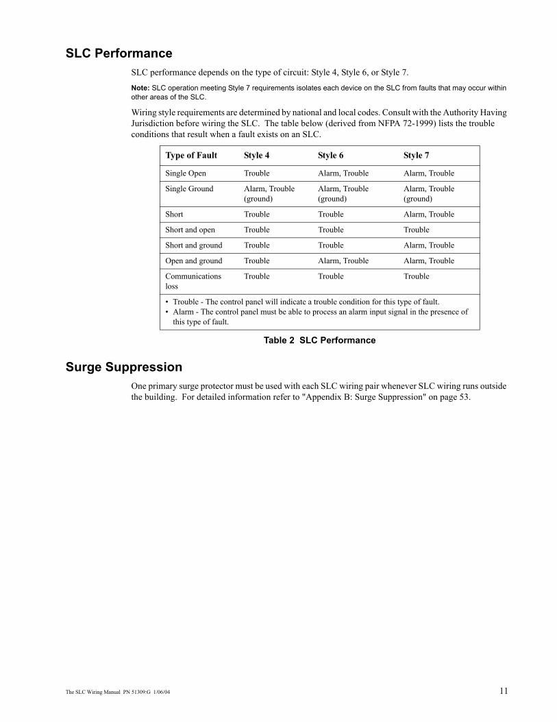
SLC PerformanceSLC performance depends on the type of circuit: Style 4, Style 6, or Style 7.
Note: SLC operation meeting Style 7 requirements isolates each device on the SLC from faults that may occur within other areas of the SLC.
Wiring style requirements are determined by national and local codes. Consult with the Authority Having Jurisdiction before wiring the SLC. The table below (derived from NFPA 72-1999) lists the trouble conditions that result when a fault exists on an SLC.
Table 2 SLC Performance
Surge SuppressionOne primary surge protector must be used with each SLC wiring pair whenever SLC wiring runs outside the building. For detailed information refer to "Appendix B: Surge Suppression" on page 53.
Type of Fault Style 4 Style 6 Style 7
Single Open Trouble Alarm, Trouble Alarm, Trouble
Single Ground Alarm, Trouble (ground)
Alarm, Trouble (ground)
Alarm, Trouble (ground)
Short Trouble Trouble Alarm, Trouble
Short and open Trouble Trouble Trouble
Short and ground Trouble Trouble Alarm, Trouble
Open and ground Trouble Alarm, Trouble Alarm, Trouble
Communications loss
Trouble Trouble Trouble
• Trouble - The control panel will indicate a trouble condition for this type of fault.• Alarm - The control panel must be able to process an alarm input signal in the presence of
this type of fault.

Wiring Requirements Wire Sizing
12 The SLC Wiring Manual PN 51309:G 1/06/04
Wiring Requirements
Wire SizingThe SLC requires use of a specific wire type to ensure proper circuit operation. It is recommended that all SLC wiring be twisted-pair shielded to minimize the effects of electrical interference. Wire size should be no smaller than 18 AWG (0.75 mm2) and no larger than 12 AWG (3.25 mm2) wire.
The wire size depends on the length of the SLC circuit. Use the table below to determine the specific wiring requirements for the SLC.
Table 3 Wire Requirements
Wire Requirements Distance in feet (meters) Typical Wire Type1
1. AWG wire size conversion to metric size: 12 AWG = 3.25mm2; 14 AWG = 2.00mm2; 16 AWG = 1.30mm2; 18 AWG = 0.75mm2
Twisted-pair shielded 10,000 (3048)
8,000 (2438)
4,875 (1486)
3,225 (983)
12 AWG - Belden 9583, Genesis 4410,Signal 98230, WPW D999
14 AWG - Belden 9581, Genesis 4408, Signal 98430, WPW D995
16 AWG - Belden 9575, Genesis 4406 & 4606, Signal 98630, WPW D991
18 AWG - Belden 9574, Genesis 4402 & 4602, Signal 98300, WPW D975
Untwisted, unshielded wire, inside conduit or not in conduit.
MS-9200= 1,000 (305)MS-9600= 3,000 (914)MS-9200UD= 3,000 (914)
12 to 18 AWG

Measuring Resistance & Length Wiring Requirements
The SLC Wiring Manual PN 51309:G 1/06/04 13
Measuring Resistance & Length
Two-Wire SLC - Style 4 (Class B)
Loop Resistance
T-tapping of the SLC wiring is permitted for 2-wire Style 4 configurations. The total DC resistance from the control panel to each branch end cannot exceed 40 ohms. Measure DC resistance as detailed and shown below:
1. With power removed, short the termination point of one branch at a time and measure the DC resistance from the beginning of the SLC to the end of that particular branch.
2. Repeat this procedure for all remaining branches in the SLC.
Figure 1 Measuring DC Resistance of a Two-Wire SLC
Total Wire Length
The total wire length of all combined branches of one SLC cannot exceed the limits set forth in each system’s instruction manual. Determine the total length in each SLC by summing the wire lengths of all branches of one SLC.
In the following figure, the total length of the SLC is determined by adding the lengths of Branch A plus Branch B plus Branch C.
Figure 2 Measuring the Total Wire Length - Two-Wire SLC
SLC
-mea
s1.c
dr
SLC Out
Branch
Short Point
Branch A Branch B Branch C
SLC
-mea
s2.c
dr
SLC Terminal Block
Wiring Requirements Measuring Resistance & Length
14 The SLC Wiring Manual PN 51309:G 1/06/04
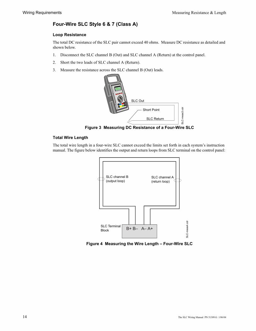
Four-Wire SLC Style 6 & 7 (Class A)
Loop Resistance
The total DC resistance of the SLC pair cannot exceed 40 ohms. Measure DC resistance as detailed and shown below.
1. Disconnect the SLC channel B (Out) and SLC channel A (Return) at the control panel.
2. Short the two leads of SLC channel A (Return).
3. Measure the resistance across the SLC channel B (Out) leads.
Figure 3 Measuring DC Resistance of a Four-Wire SLC
Total Wire Length
The total wire length in a four-wire SLC cannot exceed the limits set forth in each system’s instruction manual. The figure below identifies the output and return loops from SLC terminal on the control panel:
Figure 4 Measuring the Wire Length – Four-Wire SLC
SLC
-mea
s3.c
dr
SLC Out
SLC Return
Short Point
B+ B– A– A+
SLC
-mea
s4.c
dr
SLC channel B (output loop)
SLC channel A (return loop)
SLC Terminal Block

Shield Wire Termination Wiring Requirements
The SLC Wiring Manual PN 51309:G 1/06/04 15
Shield Wire TerminationThe drawing below shows the method of proper termination of the shield.
Connect the metal conduit to the cabinet by using the proper connector. Feed the shielded wire through the conduit, into the control box. The shield drain wire must be connected to the “shield” terminal on the SLC terminal block.
Note: Use of good wiring practice consistent with local electrical codes is expected.
CAUTION: Do not let the shield drain wire or the shield foil touch the system cabinet or be connected to earth ground at any point.
Figure 5 Shield Termination
Cabinet
SLC
-shi
eldt
erm
.cdr
Shield Drain Wire
Shield Foil
Conduit

Wiring Requirements Control Panel Terminal Blocks
16 The SLC Wiring Manual PN 51309:G 1/06/04
Control Panel Terminal BlocksThe terminal blocks on the control panel circuit board that concern the SLC circuit are described below. For more information on this subject refer to the control panel’s Instruction Manual.
MS-9200TB4 provides three types of 24 VDC power; Unregulated, Nonresettable and Resettable.
TB6 provides connections for the SLC wiring.
Figure 6 MS-9200 Terminal Blocks
MS-9600TB3 provides two types of 24 VDC power; Nonresettable and Resettable.
TB8 provides connections for the SLC wiring.
Figure 7 MS-9600 Terminal Blocks
TB6
SHIELD SLC SLC
TB4
SLC
-920
0tb.
cdr
SLC Return
SLC Out
Connections for wire shield
Unregulated PowerNonresettable Power
Resettable Power
TB8
SHIELDSLC SLC SLC SLC
TB3
SLC Return
SLC Out
Connections for wire shield
Nonresettable Power
Resettable Power
SLC
-960
0tb.
cdr

The SLC Wiring Manual PN 51309:G 1/06/04 17
MS-9200UDTB1 provides two types of 24 VDC power; Nonresettable and Resettable.
TB10 provides connections for the SLC wiring.
Figure 8 MS-9200UD Terminal Blocks
SLC Out
Connections for wire shield
Resettable Power
Nonresettable
SLC
-920
0udt
b.cd
r
TB10
SLC
TB1
SLC Out
SLC Return

Non-Isolated Circuits Overview
18 The SLC Wiring Manual PN 51309:G 1/06/04
Non-Isolated Circuits
OverviewThis chapter concerns itself with the two styles of circuits that do not require isolation devices:
• NFPA Style 4• NFPA Style 6
NFPA Style 4 SLCNFPA Style 4 requirements can be met by using the diagram below.
• T-tapping of the SLC wiring is allowed for Style 4 configuration.
Figure 9 Basic NFPA Style 4 SLC
SLC
-sty
le4.
cdr
Two-wire Addressable Detector
Addressable Module
T-tapped Circuits
Control PanelSLC
B+ B–

The SLC Wiring Manual PN 51309:G 1/06/04 19
NFPA Style 6 SLCNFPA Style 6 requirements can be met by using the diagram below.
• T-tapping of the SLC wiring is NOT allowed for Style 6 configuration.
Figure 10 Basic NFPA Style 6 SLC
Control PanelSLC
Two-wire Addressable Detector
Addressable Module
SLC
-sty
le6.
cdr
SLC Return
SLC Out
B+ B– A– A+

SLC Circuits with Isolators Fault Isolator Module - I300
20 The SLC Wiring Manual PN 51309:G 1/06/04
SLC Circuits with Isolators
Fault Isolator Module - I300The I300 is used to protect critical elements of the SLC from faults on other SLC branches or segments
A Fault Isolator Module on both sides of a device is required to comply with NFPA Style 7 requirements.
A maximum of 25 addressable devices can be connected between isolator Modules.
When more than 100 Isolator Modules are connected to an SLC loop, the address capacity of the loop is reduced by two (2) addresses for every isolator device in excess of 100.
Isolating an SLC BranchThe module continuously monitors the circuit connected to terminals 3(–) and 4(+). Upon power-up, an integral relay is latched on. The module periodically pulses the coil of this relay. A short circuit on the SLC resets the relay. The module detects the short and disconnects the faulted SLC branch or segment by opening the positive side of the SLC (terminal 4). This isolates the faulty branch from the remainder of the loop preventing a communication problem with all other addressable devices on the remaining branches (labeled “Continuation of the SLC” in the figure below). During a fault condition, the control panel registers a trouble condition for each addressable device which is isolated on the SLC segment or branch. Once the fault is removed, the module automatically reapplies power to the SLC branch or segment.
Wiring an Isolator ModuleThe figure below shows typical wiring of an Isolator Module:
Figure 11 Wiring an I300 Module
SLC Isolated branch of the SLC
SLC
-isow
ire.c
dr
Continuation of the SLC
OUT
OUT
IN
IN

NFPA Style 4 SLC Using an I300 Module SLC Circuits with Isolators
The SLC Wiring Manual PN 51309:G 1/06/04 21
NFPA Style 4 SLC Using an I300 ModuleA variation of a Style 4 operation using isolator modules to protect each branch of the SLC. Refer to Figure 11 on page 20 for I300 wiring.
Figure 12 NFPA Style 4 SLC using I300 modules
I300
I300
I300
1234
1234
1234
Two-wire Addressable Detector
Addressable Pull Station
SLC
-sty
le4i
300.
cdr
Control PanelSLC
Isolated Branch
B– B+
Isolated Branch
Isolated Branch

SLC Circuits with Isolators NFPA Style 6 SLC Using an I300 Module
22 The SLC Wiring Manual PN 51309:G 1/06/04
NFPA Style 6 SLC Using an I300 ModuleA variation of Style 6 operation using isolator modules to protect a section of the SLC. By flanking each group of devices with an I300 fault isolator module each group is protected from faults that may occur in the other groups. For example, a fault in Section B will not effect Sections A & C. The isolator modules on either side of Section B will open the loop. Section A will still operate from power on the SLC Out side and Section C will operate from the SLC Return side.
• A combination of isolator modules and isolator bases may be used.• T-tapping is NOT allowed within the Style 6 configuration.• I300 modules shall be within 20 feet (6.1 meters) of device and use metal conduit.
Figure 13 NFPA Style 6 SLC using I300 modules
1
2
3
4
I3001
2
3
4I300
2 1I300
4 3
3 4I300
1 2
SLC Out SLC Return
SLC
-sty
le6i
300.
cdr
Control Panel
B– B+ A+ A–
Two-wire Addressable Detector
AddressablePull Station
Section B
Section C
Section A
Cabinet or Enclosure

The SLC Wiring Manual PN 51309:G 1/06/04 23
NFPA Style 7 SLC Using an I300 ModuleStyle 7 operation requires using isolator modules before and after each device. Flanking each device with an isolator provides fault protection to all other devices on the loop.
• T-tapping is NOT allowed within the Style 7 wiring configuration.• When a detector base or pull station is used, install I300 modules on both sides of the device.• Connections between isolator modules and the device they isolate must be “close nippled” conduit,
within 3 feet (91.44 cm).
Figure 14 NFPA Style 7 SLC
1
2
3
4I300
1
2
3
4I300
2 1I300
4 3
3 4I3001 2
3 4I3001 2
3 4I3001 2
2 1I300
4 3
3 4I3001 2
B– B+ A+ A–
SLC
-sty
le7i
300.
cdr
SLC Out SLC Return
Two-Wire Addressable Detector
AddressablePull Station
Control Panel
Two-wire Addressable Detector

Monitor Modules Descriptions
24 The SLC Wiring Manual PN 51309:G 1/06/04
Monitor Modules
DescriptionsThese addressable modules monitor conventional contact-type alarm initiating devices. You can configure module circuits as an NFPA Style B (Class B) or Style D (Class A) Initiating Device Circuits (IDC). There is no limit to the number of contact-type devices installed on a monitor module circuit.
Note: For more information on the individual module specifications refer to the Installation Instructions that are provided with these devices.
MMF-300 Monitor ModuleAn addressable module that monitors either a Style B (Class B) or Style D (Class A) circuit of dry-contact input devices.
MMF-302 Monitor ModuleSimilar to the MMF-300, except it is used to monitor a single IDC of UL listed compatible two-wire smoke detectors. Refer to the Device Compatibility Document.
Figure 15 MMF-300 / MMF-302 Modules
MDF-300 Dual Monitor ModuleSimilar to the MMF-300 but provides for two independent 2-wire IDCs at two separate, consecutive addresses.
MMF-301 Monitor ModuleFunctionally and electrically identical to an MMF-300, but offered in a smaller package for mounting directly in the electrical box of the Style B (Class B) device being monitored.
Figure 16 MMF-301 Module
8 910111213
1415012345 6 7
8 9
012345 6 7
TENS
ONESLOOPLOOP ADDRESSADDRESS
89
765
98765
0
12344321
0
TENS
ONES
8 9
012345 6 7
8 910111213
1415012345 6 7
MM
F-30
0.cd
r
Rotary Switches
Areas used to record the device address and SLC number.
IDC Return +IDC Return –
IDC Out +IDC Out –
SLC –SLC +24 VDC – (MMF-302 only)24 VDC + (MMF-302 only)
0
10111213
14 15 ADDRESS
LOOP
1234
TENS ONES6789
5
0 1234
67895
FMM
-101
.cdr
Label – Use to record the device address and SLC number.
Rotary Switches
IDC (+)
IDC (-)
SLC (+)
SLC (-)

Descriptions Monitor Modules
The SLC Wiring Manual PN 51309:G 1/06/04 25
MMF-300-10A monitor module intended to interface between the FACP and up to ten (10) Style B (Class B) or five (5) Style D (Class A) IDCs containing normally open contact devices.
This type of module is contained in either a BB-2 or BB-6 cabinet. The BB-2 can accommodate up to 2 modules and the BB-6, which requires the CH-6 chassis, can accommodate up to 6 modules.
See the Installation Instructions provided with module for proper installation into cabinet.
Figure 17 MMF-300-10 Module
– +– +
J1
+0 +1 +2 +3 +4 +5 +6 +7 +8 +9
A/B
SELECT
CL
DISA
BLE 1
DISA
BLE 2
T1T0 T2 T3 T4
T5
SW1
BA
SE ADD
RESS
01
2 3 4 56
78
91011
1314
15
12
01
2 3 4 56
78
9
– + – +– + – + – + – +– +– + – +– +
Disable AddressPlace shunt in:Disable 1 position to disable highest module addressDisable 2 position to disable highest two module addresses
Style Y or Style Z SelectRemove shunt for Style Z circuits
SLC Address Set rotary switches to base (first) address of modules

Monitor Modules Descriptions
26 The SLC Wiring Manual PN 51309:G 1/06/04
MMF-302-6A monitor module intended to interface between the FACP and a conventional alarm system with up to six (6) Style B (Class B) or three (3) Style D (Class A) IDCs containing normally open contact devices.
This type of module is contained in either a BB-2 or BB-6 cabinet. The BB-2 can accommodate up to 2 modules and the BB-6, which requires the CH-6 chassis, can accommodate up to 6 modules.
See the Installation Instructions provided with module for proper installation into cabinet.
Figure 18 MMF-302-6 Module
– +– +
T6
J1
BASE ADDRESS +0 BASE ADDRESS +1 BASE ADDRESS +2 BASE ADDRESS +3 BASE ADDRESS +4 BASE ADDRESS +5
A/B
SELECT
A/B
SELECT
DISA
BLE 1
DISA
BLE 2
T1T0
T2 T3 T4
T5
SW1
BASE ADDRESS
01
2 3 4 56
78
91011
1314
15
12
01
2 3 4 56
78
9
– +– + – + – +– + – + – +– +
Disable AddressPlace shunt in:Disable 1 position to disable highest module addressDisable 2 position to disable highest two module addresses
Style Y or Style Z SelectRemove shunt for Style Z circuits
SLC Address Set rotary switches to base (first) address of modules

Installation Monitor Modules
The SLC Wiring Manual PN 51309:G 1/06/04 27
InstallationWhen installing any of these modules DO NOT mix the following services that the IDC provides:
• Fire alarm service• Automatic and manual waterflow alarm service with normally open contact devices• Sprinkler supervision with normally open contact devices
Setting an SLC address for a Single Point ModuleEach module can be set to one of 159 addresses (01-159) and is factory preset with an address of “00”.Note: The MS-9200 and MS-9200UD can support module addresses of 01 - 99. The MS-9600 can support module addresses 01 - 159.
To set an SLC address, use a screwdriver to adjust the rotary switches on the module to the desired address. The module below is set at “35”. When finished, mark the address on the module face in the place provided.
Figure 19 Setting SLC Address on a Single Point Module
Setting an SLC address for a Multi-Point ModuleIn Class B operation, each MMF-300-10, MMF-302-6, CMF-300-6 and CRF-300-6 module is set to a base address. The remaining module points are automatically assigned to the next higher SLC addresses. For example, if the base address of a MMF-300-10 is set to 28, the next module points will be addressed to 29, 30, 31, 32, 33, 34, 35, 36 and 37.
In Class A operation, alternate module points are paired together, resulting in a total of five module points. For example, if the base address of a MMF-300-10 is set to 28, then 30, 32, 34 and 36 will be automatically assigned to the remaining module points and 29, 31, 33, 35 and 37 are available for use by other modules.Note: The MS-9200 and MS-9200UD can support module addresses of 01 - 99. The MS-9600 can support module addresses 01 - 159 (the plastic stop located on the Tens switch must be removed to set addresses above 99).
To set an SLC address, use a common screwdriver to adjust the rotary switches on the module to the desired address. The module below is set at “28”.
Figure 20 Setting SLC Address on a Multi-Point Module
TENS
ONES
8 910111213
1415012345 6 7
8 9
012345 6 7
SLC
-set
add.
cdr
Rotary Switches0
12 3 4 5
67
891011
1314
15
12
01
2 3 4 56
78
9 mul
troty
.cdr
Rotary SwitchesPlastic Stop
TENS
ONES

Monitor Modules MMF-300 Wiring Diagrams
28 The SLC Wiring Manual PN 51309:G 1/06/04
MMF-300 Wiring DiagramsFollowing are wiring diagrams that depict NFPA Style B (Class B) and D (Class A) Initiating Device Circuits (IDCs) using MMF-300 monitor modules.
The Initiating Device Circuit (IDC) is supervised and current-limited to 210 microamperes @ 24 VDC (nominal).
Wiring a NFPA Style B IDC with an MMF-300Connect the SLC wiring to the module terminals 1 (–) and 2 (+).
Each module takes one address on the SLC. Use the rotary switches on the module to set it to the required SLC address. Refer to “Setting an SLC address for a Single Point Module” on page 27.
The figure below shows typical wiring for a supervised and power-limited NFPA Style B IDC using an MMF-300 module.
• Refer to the Device Compatibility Document for compatible smoke detectors.• See "Appendix A: Power Considerations" on page 49 for information on supervising 24 VDC
power.
Figure 21 Typical Style B IDC Wiring with MMF-300
8 910111213
1415012345 6 7
8 9
012345 6 7
TENS
ONESLOOPLOOP ADDRESSADDRESS
89
765
98765
0
12344321
0
TENS
ONES
8 9
012345 6 7
8 910111213
1415012345 6 7
SLC
-idcB
1.cd
r
47K ELR(supplied with module)
Heat detector
SLC
MMF-300
IDC Out
24 VDC PowerFiltered, Regulated, Resettable
24 VDC Four-wire Detector Base
Manual pull station

MMF-300 Wiring Diagrams Monitor Modules
The SLC Wiring Manual PN 51309:G 1/06/04 29
Wiring a NFPA Style D IDC with an MMF-300Connect the SLC wiring to the module terminals 1 (–) and 2 (+).
Each module takes one address on the SLC. Use the rotary switches on the module to set it to the required SLC address. Refer to “Setting an SLC address for a Single Point Module” on page 27.
The figure below shows typical wiring for a supervised and power-limited NFPA Style D (Class A) IDC using an MMF-300 module.
• Refer to the Device Compatibility Document for compatible smoke detectors.• See "Appendix A: Power Considerations" on page 49 for information on supervising 24 VDC
power.
Figure 22 Typical Style D IDC Wiring with MMF-300
8 910111213
1415012345 6 7
8 9
012345 6 7
TENS
ONESLOOPLOOP ADDRESSADDRESS
89
765
98765
0
12344321
0
TENS
ONES
8 9
012345 6 7
8 910111213
1415012345 6 7
SLC
-idcD
1.cd
r
24 VDC Four-wire Detector Base
Manual pull station
Heat detector
SLC
MMF-300
IDC Out
24 VDC PowerFiltered, Regulated, Resettable
IDC Return

Monitor Modules MMF-300-10 Wiring Diagrams
30 The SLC Wiring Manual PN 51309:G 1/06/04
MMF-300-10 Wiring DiagramsFollowing are wiring diagrams that depict NFPA Style B (Class B) and D (Class A) Initiating Device Circuits (IDCs) using MMF-300-10 monitor modules.
The Initiating Device Circuit (IDC) is supervised and current-limited to 1.0 milliampere @ 24 VDC (nominal).
Wiring a NFPA Style B IDC with an MMF-300-10Connect the SLC wiring to the module terminals T5 as shown below.
Use the rotary switches on the module to set the base SLC address. Each module takes ten addresses on the SLC. The remaining module points are automatically assigned to the next nine higher addresses. Refer to “Setting an SLC address for a Multi-Point Module” on page 27.
DO NOT set the lowest address above 150 (90 for the MS-9200 and MS-9200UD), as the other module points will be assigned to nonexistent addresses.
The figure below shows typical wiring for a supervised and power-limited NFPA Style B IDC using an MMF-300-10 module.
• Refer to the Device Compatibility Document for compatible smoke detectors.• See "Appendix A: Power Considerations" on page 49 for information on supervising 24 VDC
power.
Figure 23 Typical Style B IDC Wiring with MMF-300-10
+–+–
– +– +
T1T0 T2 T3 T4
T5
– + – +– + – + – + – +– +– + – +– +
24 VDC PowerFiltered, Regulated, Resettable
24 VDC Four-wire Detector Base
Manual Pull Station
Heat Detector
MMF-300-10SLC
47K ELR(supplied with module)
IDC Out
SLC
-idcB
4.cd
r

MMF-300-10 Wiring Diagrams Monitor Modules
The SLC Wiring Manual PN 51309:G 1/06/04 31
Wiring a NFPA Style D IDC with an MMF-300-10Connect the SLC wiring to the module terminals T5 as shown below.
Use the rotary switches on the module to set the base SLC address. Each module takes five alternating addresses on the SLC. The remaining module points are automatically assigned to the next four higher addresses. (Example: 28, 30, 32, 34 and 36). Refer to “Setting an SLC address for a Multi-Point Module” on page 27.
DO NOT set the lowest address above 150 (90 for the MS-9200 and MS-9200UD), as the other module points will be assigned to nonexistent addresses.
The figure below shows typical wiring for a supervised and power-limited NFPA Style D (Class A) IDC using an MMF-300-10 module.
• Refer to the Device Compatibility Document for compatible smoke detectors.• See "Appendix A: Power Considerations" on page 49 for information on supervising 24 VDC
power.
Figure 24 Typical Style D IDC Wiring with MMF-300-10
+–+–
– +– +
T1T0 T2 T3 T4
T5
– + – +– + – + – + – +– +– + – +– +
24 VDC PowerFiltered, Regulated, Resettable
24 VDC Four-wire Detector Base
Manual Pull Station
Heat Detector
IDC Out
MMF-300-10SLC
IDCReturn
SLC
-idcD
3.cd
r

Monitor Modules MDF-300 Wiring Diagrams
32 The SLC Wiring Manual PN 51309:G 1/06/04
MDF-300 Wiring DiagramsFollowing is a wiring diagrams that depict NFPA Style B (Class B) Initiating Device Circuits (IDCs) using MDF-300 dual monitor module.
Wiring a NFPA Style B IDC with an MDF-300Connect the SLC wiring to the module terminals 1 (–) and 2 (+).
Use the rotary switches on the module to set it to the SLC address. Each dual module takes two addresses on the SLC. Circuit ‘L’ corresponds to the address set on the rotary switches, which will be an even number. Circuit ‘H’ will automatically respond to the next higher address, which will be an odd number. Use caution to avoid duplicate addressing of modules on the system. Refer to “Setting an SLC address for a Single Point Module” on page 27.
Each IDC (H & L) is power limited to 230 microamperes @ 24 VDC.
The figure below shows typical wiring for a supervised and power-limited NFPA Style B IDC using an MDF-300 module.
• Refer to the Device Compatibility Document for compatible smoke detectors.• See "Appendix A: Power Considerations" on page 49 for information on supervising 24 VDC
power.
Figure 25 Typical Style B IDC Wiring with MDF-300
8 910111213
1415012345 6 7
TENS
LOOPLOOP ADDRESSADDRESS
89
765
98765
0
12344321
0
TENS
8 910111213
1415012345 6 7
ONESONES02
46
8
0246
8
47K ELR (supplied with module)
SLC
MDF-300
Manual Pull Station
Heat Detector
47K ELR (supplied with module)
SLC
-idcB
3.cd
r
Circuit H
Circuit L
MMF-302 Wiring Diagrams Monitor Modules
The SLC Wiring Manual PN 51309:G 1/06/04 33
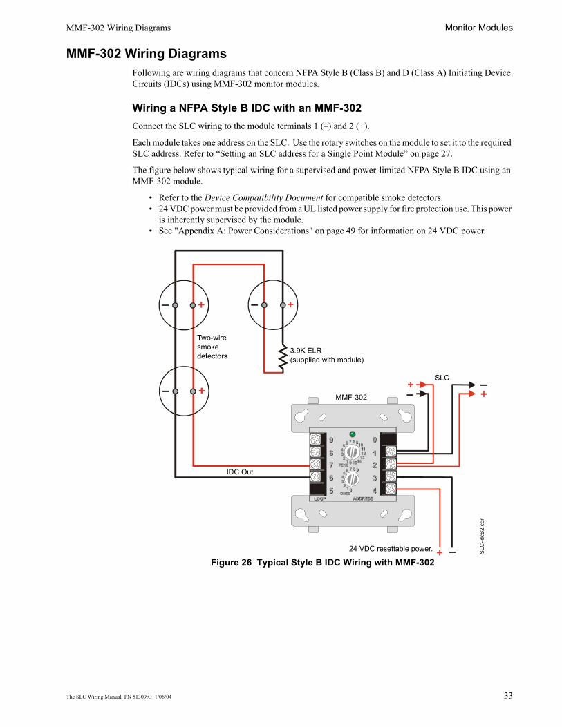
MMF-302 Wiring DiagramsFollowing are wiring diagrams that concern NFPA Style B (Class B) and D (Class A) Initiating Device Circuits (IDCs) using MMF-302 monitor modules.
Wiring a NFPA Style B IDC with an MMF-302Connect the SLC wiring to the module terminals 1 (–) and 2 (+).
Each module takes one address on the SLC. Use the rotary switches on the module to set it to the required SLC address. Refer to “Setting an SLC address for a Single Point Module” on page 27.
The figure below shows typical wiring for a supervised and power-limited NFPA Style B IDC using an MMF-302 module.
• Refer to the Device Compatibility Document for compatible smoke detectors.• 24 VDC power must be provided from a UL listed power supply for fire protection use. This power
is inherently supervised by the module.• See "Appendix A: Power Considerations" on page 49 for information on 24 VDC power.
Figure 26 Typical Style B IDC Wiring with MMF-302
8 910111213
1415012345 6 7
8 9
012345 6 7
TENS
ONESLOOPLOOP ADDRESSADDRESS
89
765
98765
0
12344321
0
TENS
ONES
8 9
012345 6 7
8 910111213
1415012345 6 7
SLC
IDC OutSL
C-id
cB2.
cdr
MMF-302
Two-wire smoke detectors
3.9K ELR(supplied with module)
24 VDC resettable power.
Monitor Modules MMF-302 Wiring Diagrams
34 The SLC Wiring Manual PN 51309:G 1/06/04
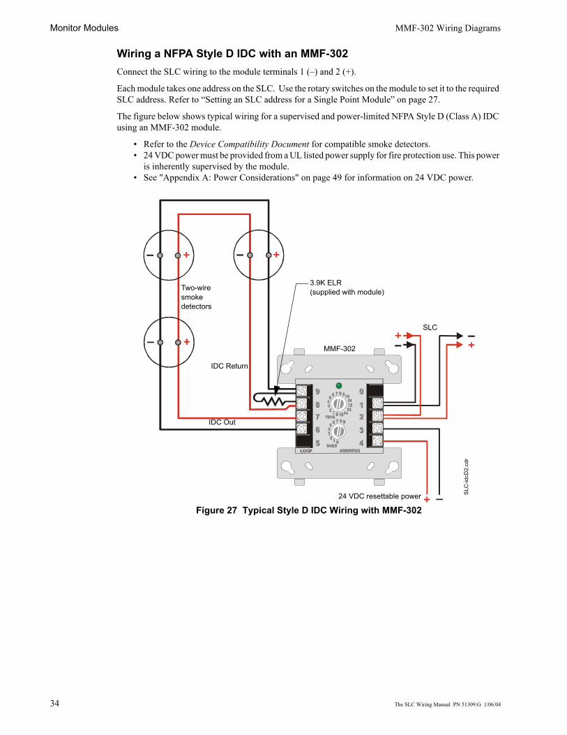
Wiring a NFPA Style D IDC with an MMF-302Connect the SLC wiring to the module terminals 1 (–) and 2 (+).
Each module takes one address on the SLC. Use the rotary switches on the module to set it to the required SLC address. Refer to “Setting an SLC address for a Single Point Module” on page 27.
The figure below shows typical wiring for a supervised and power-limited NFPA Style D (Class A) IDC using an MMF-302 module.
• Refer to the Device Compatibility Document for compatible smoke detectors.• 24 VDC power must be provided from a UL listed power supply for fire protection use. This power
is inherently supervised by the module.• See "Appendix A: Power Considerations" on page 49 for information on 24 VDC power.
Figure 27 Typical Style D IDC Wiring with MMF-302
8 910111213
1415012345 6 7
8 9
012345 6 7
TENS
ONESLOOPLOOP ADDRESSADDRESS
89
765
98765
0
12344321
0
TENS
ONES
8 9
012345 6 7
8 910111213
1415012345 6 7
SLC
Two-wire smoke detectors
3.9K ELR(supplied with module)
IDC Out
MMF-302
SLC
-idcD
2.cd
r
IDC Return
24 VDC resettable power

The SLC Wiring Manual PN 51309:G 1/06/04 35
MMF-302-6 Wiring DiagramsFollowing are wiring diagrams that concern NFPA Style B (Class B) and D (Class A) Initiating Device Circuits (IDCs) using MMF-302-6 monitor modules.
Wiring a NFPA Style B IDC with an MMF-302-6Connect the SLC wiring to the module terminals T0 as shown below.
Use the rotary switches on the module to set the base SLC address. Each module takes six addresses on the SLC. The remaining module points are automatically assigned to the next five higher addresses. Refer to “Setting an SLC address for a Multi-Point Module” on page 27.
DO NOT set the lowest address above 154 (94 for the MS-9200 and MS-9200UD), as the other module points will be assigned to nonexistent addresses.
The figure below shows typical wiring for a supervised and power-limited NFPA Style B IDC using an MMF-302-6 module.
• Refer to the Device Compatibility Document for compatible smoke detectors.• 24 VDC power must be provided from a UL listed power supply for fire protection use. This power
is inherently supervised by the module.• See "Appendix A: Power Considerations" on page 49 for information on 24 VDC power.
Figure 28 Typical Style B IDC Wiring with MMF-302-6
+–+–+–
– +– +
T1T0
T2 T3 T4
– +– + – + – +– + – + – +– +
Two-wire smoke detectors
IDC Out
MMF-302-6
24 VDC resettable power
3.9K ELR(supplied with module)
SLC
-idcB
5.cd
r
SLC

Monitor Modules MMF-302-6 Wiring Diagrams
36 The SLC Wiring Manual PN 51309:G 1/06/04
Wiring a NFPA Style D IDC with an MMF-302-6Connect the SLC wiring to the module terminals T0 as shown below.
Use the rotary switches on the module to set it to the SLC addresses. Each module takes three alternating addresses on the SLC. The remaining module points are automatically assigned to the next two higher addresses. (Example: 28, 30 and 32). Refer to “Setting an SLC address for a Multi-Point Module” on page 27.
DO NOT set the lowest address above 154 (94 for the MS-9200 and MS-9200UD), as the other module points will be assigned to nonexistent addresses.
The figure below shows typical wiring for a supervised and power-limited NFPA Style D (Class A) IDC using an MMF-302-6 module.
• Refer to the Device Compatibility Document for compatible smoke detectors.• 24 VDC power must be provided from a UL listed power supply for fire protection use. This power
is inherently supervised by the module.• See "Appendix A: Power Considerations" on page 49 for information on 24 VDC power.
Figure 29 Typical Style D IDC Wiring with MMF-302-6
++
––
+–
– +– +
T1T0
T2 T3 T4
– +– + – + – +– + – + – +– +
SLC
-idcD
4.cd
r
Two-wire smoke detectors
24 VDC resettable power
MMF-302-6
IDC Out
SLC
IDCReturn

Description Control Modules
The SLC Wiring Manual PN 51309:G 1/06/04 37
Control Modules
DescriptionThe CMF-300 and CMF-300-6 modules are addressable modules that can be used for monitoring and switching 24 VDC Notification Appliance Circuit (NAC) power for NFPA Style Y (Class B) and NFPA Style Z (Class A) circuits.
Ratings for the relay contacts on the module are:
Note: For more information on the module specifications refer to the Installation Instructions provided with these devices.
CMF-300 Installation
Setting an SLC address for an CMF-300 ModuleEach module is factory preset with an address of “00”. To set an SLC address refer to "Setting an SLC address for a Single Point Module" on page 27.
Wiring a Notification Appliance Circuit (NAC) with an CMF-300The figure below shows the connections to wire a module for powering a 24 VDC NAC:
Figure 30 CMF-300 Wiring Connections
Load Description Application Maximum Voltage Current Rating
Resistive Non-Coded 30 VDC 3.0 A
Resistive Coded 30 VDC 2.0 A
Resistive Non-Coded 110 VDC 0.9 A
Resistive Non-Coded 125 VAC (CMF-300)70.7 VAC (CMF-300-6)
0.9 A
Inductive (L/R = 5ms) Coded 30 VDC 0.5 A
Inductive (L/R = 2ms) Coded 30 VDC 1.0 A
Inductive (PF = 0.35) Non-Coded 125 VAC (CMF-300)70.7 VAC (CMF-300-6)
0.5 A
8 910111213
1415012
345 6 7
8 9
012345 6 7
TENS
ONESLOOPLOOP ADDRESSADDRESS
8
9
765
9
876
5
0
12
3443
21
0
TENS
ONES
8 9
012345
6 7
8 9101112
131415012
345 6 7
SLC (–)
SLC (+)
24 VDC Nonresettable Power (–)
24 VDC Nonresettable Power (+)
Style Z NAC (+)
Style Z NAC (–)
Style Y NAC (–)
Style Y NAC (+)
FMM
-1.c
dr

Control Modules Wiring an CMF-300 Module
38 The SLC Wiring Manual PN 51309:G 1/06/04
Wiring an CMF-300 ModuleThis section contains instructions and diagrams for wiring a Signaling Line Circuit with an CMF-300 as a Notification Appliance Circuit (NAC).
Wiring a Style Y NAC (Two-Wire)A supervised and power-limited NFPA Style Y (Class B) NAC using a CMF-300 module. Polarized alarm notification appliances are shown connected to the module in a two-wire configuration.
Note: Refer to Device Compatibility Document for compatible notification appliances and relays.
• See "Appendix A: Power Considerations" on page 49 for information on monitoring 24 VDC power.• Each module can control 2 amps of resistive load (on electronic devices) or 1 amp of inductive load
(on mechanical bells and horns).• 24 VDC power must be provided from a UL listed power supply for fire protection use.• A power supervision relay is required only on the last module of the power run.• Do not T-tap or branch a Style Y circuit. • Terminate the circuit across the last device using an End-of-Line Resistor 47K, 1/2-watt,
P/N SSD A2143-00 (ELR-47K in Canada).• Do not loop wiring under the screw terminals of any notification appliance. To maintain
supervision, break the wire run at each device
Figure 31 NFPA Style Y Notification Appliance Circuit
8 910111213
1415012345 6 7
8 9
012345 6 7
TENS
ONESLOOPLOOP ADDRESSADDRESS
89
765
98765
0
12344321
0
TENS
ONES
8 9
012345 6 7
8 910111213
1415012345 6 7
ELR 47K, 1/2-watt
24 VDC Notification Appliances
CMF-300
SLC
NAC Out
SLC
-nac
Y.cd
r
24 VDC nonresettable power

Wiring an CMF-300 Module Control Modules
The SLC Wiring Manual PN 51309:G 1/06/04 39
Wiring a Style Z NAC (Four-Wire)A supervised and power-limited NFPA Style Z (Class A) NAC using a CMF-300 module. Polarized alarm notification appliances are shown connected to the module in a four-wire configuration.
Note: Refer to the Device Compatibility Document for compatible notification appliances and relays.
• See "Appendix A: Power Considerations" on page 49 for information on monitoring 24 VDC power.• Each module can control 2 amps of resistive load (on electronic devices) or 1 amp of inductive load
(on mechanical bells and horns). • 24 VDC power must be provided from a UL listed power supply for fire protection use.• A power supervision relay is required only on the last module of the power run.• Do not T-tap or branch a Style Z circuit. • Do not loop wiring under the screw terminals of any notification appliance. To maintain
supervision, break the wire run at each device.
Figure 32 NFPA Style Z Notification Appliance Circuit
8 910111213
1415012345 6 7
8 9
012345 6 7
TENS
ONESLOOPLOOP ADDRESSADDRESS
89
765
98765
0
12344321
0
TENS
ONES
8 9
012345 6 7
8 910111213
1415012345 6 7
24 VDC notification appliances
CMF-300
NAC Out
24 VDC nonresettable power
SLC
SLC
-nac
Z.cd
r
NAC Return

Control Modules CMF-300-6 Installation
40 The SLC Wiring Manual PN 51309:G 1/06/04
CMF-300-6 Installation
Cabinet InstallationThis type of module is contained in either a BB-2 or BB-6 cabinet. The BB-2 can accommodate up to 2 modules and the BB-6, which requires the CH-6 chassis, can accommodate up to 6 modules.
See the Installation Instructions provided with module for proper installation into cabinet.
Setting an SLC address for an CMF-300-6 ModuleIn “Style Y” operation each CMF-300-6 module can be set to one of 154 base addresses (01-154). The remaining module points are automatically assigned to the next five higher SLC addresses. For example, if the base address is set to 28, the next five module points will be addressed to 29, 30, 31, 32 and 33.
In “Style Z” operation alternate module points are paired together, resulting in a total of three module points. For example, if the base address is set to 28, then 30 and 32 will be automatically assigned to the remaining module points and 29, 31 and 33 are available to be used for other modules on the SLC.
DO NOT set the lowest address above 154 (94 for MS-9200 and MS-9200UD), as the other module points will be assigned to nonexistent addresses.
Note: The MS-9200 and MS-9200UD can support module addresses of 01 - 99. The MS-9600 can support module addresses 01 - 159.
To set an SLC address, use a common screwdriver to adjust the rotary switches on the module to the desired address. See Figure 33 on page 41.
Note: For use with a MS-9600, remove the stop on the upper rotary switch.
Setting NACs as Style Y or Style ZTo use this module for Style Y (Class B) operation ascertain that a small shunt is installed on the “A/B SELECT” set of pins. (As shipped).
To use this module for Style Z (Class A) operation remove the small shunt from the “A/B SELECT” set of pins. See drawing below and Figure 33 on page 41.
Disabling Unused Module AddressesA shunt is used, in conjunction with a pin block, to disable a maximum of three (3) unused module addresses. If two module addresses are disabled, the lowest four addresses will be functional, while the highest two will be disabled. For example, if the shunt is placed on ‘DISABLE 2’ and the base address is set to 28, the module addresses will be assigned to 28, 29, 30 and 31.
In Style Z operation, placing a small shunt on ‘DISABLE 3’ will disable all three addresses. Placing it on ‘DISABLE 2’ will disable two out of three addresses.
To disable addresses, securely place one of the supplied small shunts onto the desired set of pins. See drawing and Figure 33 on page 41.
Short Circuit ProtectionProtection is disabled for each module address when there is a large shunt installed on the corresponding pins of the pin block (as shipped, all six addresses are disabled).
When enabled, the module will not switch power supply if a short circuit condition exists on a NAC.
To enable “Short Circuit Protection” for an address, remove the large shunt from the corresponding pins of the pin block. See Figure 33 on page 41. Place unused shunts on single pin to store on board for future use.
J1
A/B SELECT
DISABLE 1
DISABLE 2
DISABLE 3
SLC
-dis
able
1.cd
r

CMF-300-6 Installation Control Modules
The SLC Wiring Manual PN 51309:G 1/06/04 41
Features Not SupportedThe “Synchronization” and “Power Supply Monitoring” features are not supported at this time.
Circuit Board Information
Figure 33 CMF-300-6 Control Module Settings
– + – + – + – + – + – + – + – + – + – +
– + – +
SYNC GENERATOR
ENABLE POWER SUPPLY MONITORS
DISABLE SHORT CIRCUIT PROTECTION
T10
J1
BASE ADDRESS +0 BASE ADDRESS +1 BASE ADDRESS +2 BASE ADDRESS +3 BASE ADDRESS +4 BASE ADDRESS +5
SW1
BA
SE AD
DR
ESS
A/B
SELECT
DISA
BLE 1
DISA
BLE 2
DISA
BLE 3
T1
+1
+0
+2 +3 +4 +5
T0
T2 T3 T4 T5
T11T12 T13 T14 T15
T16
01
2 3 4 56
78
91011
1314
15
12
01
2 3 4 56
78
9
CM
F-30
0-6.
cdr
Synchronization Generator -Not Supported. DO NOT remove shunts.
Power Supply Monitors -Not Supported. DO NOT remove shunts.
Disable Address -Place shunt onto required pins.
SelectStyle Y (Class B) or
Style Z (Class A) -Remove shunt for Style Z (Class A).
Short Circuit Protection - Remove shunt from the corresponding pins to enable. Shunt #1 for first address, #2 for second address, etc.
#1 #2 #3 #4 #5 #6
SLC AddressSet rotary switches to address required.
Status IndicatorsGreen LEDs are controlled by FACP to indicate status of each module address.

Control Modules Wiring an CMF-300-6 Module
42 The SLC Wiring Manual PN 51309:G 1/06/04
Wiring an CMF-300-6 ModuleThis section contains basic instructions and diagrams for wiring a Signaling Line Circuit with an CMF-300-6 as a Notification Appliance Circuit (NAC).
For more detailed information on wiring a CMF-300-6 Control Module refer to the Installation Instructions provided with the module. Included in these instructions are wiring diagrams concerning a single power supply being shared by multiple NACs and audio NAC configurations.
Wiring a Style Y NAC (Two-Wire)A supervised and power-limited NFPA Style Y (Class B) NAC with a single power supply dedicated to a single NAC using a CMF-300-6 module. Polarized alarm notification appliances are shown connected to the module in a two-wire configuration.
Note: Refer to Device Compatibility Document for compatible notification appliances and relays.
• See "Appendix A: Power Considerations" on page 49 for information on monitoring 24 VDC power.• Each module can control 2 amps of resistive load (on electronic devices) or 1 amp of inductive load
(on mechanical bells and horns).• 24 VDC power must be provided from a UL listed power supply for fire protection use.• A power supervision relay is required only on the last module of the power run.• Do not T-tap or branch a Style Y circuit. • Terminate the circuit across the last device using an End-of-Line Resistor 47K, 1/2-watt,
P/N SSD A2143-00 (ELR-47K in Canada).• Do not loop wiring under the screw terminals of any notification appliance. To maintain
supervision, break the wire run at each device.
Figure 34 NFPA Style Y Notification Appliance Circuit
+
+
–
–
– + – + – + – + – + – + – + – + – + – +
– + – +
T10
T1
+1 +2 +3 +4 +5
T0+0
T2 T3 T4 T5
T11T12 T13 T14 T15
T16
24 VDC notification appliances
NAC Out
24 VDC nonresettable power
SLC
-nac
Y2.c
dr
Power Supervision Relay(A77-716B)
SLC
CMF-300-6
ELR 47K, 1/2-watt
Relay Connector Assembly

The SLC Wiring Manual PN 51309:G 1/06/04 43
Wiring a Style Z NAC (Four-Wire)A supervised and power-limited NFPA Style Z (Class A) NAC with a single power supply dedicated to a single NAC using a CMF-300-6 module. Polarized alarm notification appliances are shown connected to the module in a four-wire configuration.
Note: Refer to the Device Compatibility Document for compatible notification appliances and relays.
• See "Appendix A: Power Considerations" on page 49 for information on monitoring 24 VDC power.• Each module can control 2 amps of resistive load (on electronic devices) or 1 amp of inductive load
(on mechanical bells and horns). • 24 VDC power must be provided from a UL listed power supply for fire protection use.• A power supervision relay is required only on the last module of the power run.• Do not T-tap or branch a Style Z circuit. • Do not loop wiring under the screw terminals of any notification appliance. To maintain
supervision, break the wire run at each device.
Figure 35 NFPA Style Z Notification Appliance Circuit
+
+
+
–
–
–+–+–
– + – + – + – + – + – + – + – + – + – +
– + – +
T10
T1
+1 +2 +3 +4 +5
T0+0
T2 T3 T4 T5
T11T12 T13 T14 T15
T16
Power Supervision Relay(A77-716B)
24 VDC notification appliances
24 VDC nonresettable power
NACOut
CMF-300-6
NACReturn
SLC
SLC
-nac
Z3.c
dr
Power Supply Jumper
Relay Connector Assembly
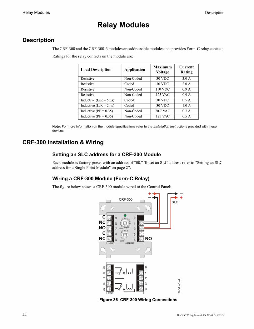
Relay Modules Description
44 The SLC Wiring Manual PN 51309:G 1/06/04
Relay Modules
DescriptionThe CRF-300 and the CRF-300-6 modules are addressable modules that provides Form-C relay contacts.
Ratings for the relay contacts on the module are:
Note: For more information on the module specifications refer to the Installation Instructions provided with these devices.
CRF-300 Installation & Wiring
Setting an SLC address for a CRF-300 ModuleEach module is factory preset with an address of “00.” To set an SLC address refer to "Setting an SLC address for a Single Point Module" on page 27.
Wiring a CRF-300 Module (Form-C Relay)The figure below shows a CRF-300 module wired to the Control Panel:
Figure 36 CRF-300 Wiring Connections
Load Description Application Maximum Voltage
Current Rating
Resistive Non-Coded 30 VDC 3.0 AResistive Coded 30 VDC 2.0 AResistive Non-Coded 110 VDC 0.9 AResistive Non-Coded 125 VAC 0.9 AInductive (L/R = 5ms) Coded 30 VDC 0.5 AInductive (L/R = 2ms) Coded 30 VDC 1.0 AInductive (PF = 0.35) Non-Coded 70.7 VAC 0.7 AInductive (PF = 0.35) Non-Coded 125 VAC 0.5 A
8 910111213
14150123456 7
8 9
012345 6 7
TENS
ONESLOOPLOOP ADDRESSADDRESS
89
765
98765
0
12344321
0
TENS
ONES
8 9
012345 6 7
8 910111213
1415012345 6 7
89
765
98765
0
12344321
0
LOOPLOOP
SLC
SLC
-frm
C.c
dr
CRF-300
NO
CNCNO
CNC

The SLC Wiring Manual PN 51309:G 1/06/04 45
CRF-300-6 Circuit Board Information
Figure 37 CRF-300-6 Control Relay Module
– +– +T102
J1
SW1
BASE
AD
DR
ESS
NO
NE
ON
ETW
OTH
REE
AD
DR
ESSD
ISAB
LE
01
2 3 4 56
78
91011
1314
15
12
01
2 3 4 56
78
9
Disable AddressPlace shunt onto required pins.
SLC AddressSet rotary switches to address required.
Status IndicatorsGreen LEDs are controlled by FACP to indicate status of each module address.

Relay Modules CRF-300-6 Installation & Wiring
46 The SLC Wiring Manual PN 51309:G 1/06/04
CRF-300-6 Installation & Wiring
Cabinet InstallationThis type of module is contained in either a BB-2 or BB-6 cabinet. The BB-2 can accommodate up to 2 modules and the BB-6, which requires the CH-6 chassis, can accommodate up to 6 modules.
See the Installation Instructions provided with module for proper installation into cabinet.
Setting an SLC address for a CRF-300-6 ModuleEach CRF-300-6 module can be set to one of 154 base addresses (01-154). The remaining module points are automatically assigned to the next five higher SLC addresses. For example, if the base address is set to 28, the next five module points will be addressed to 29, 30, 31, 32 and 33.
DO NOT set the lowest address above 154 (94 for MS-9200 and MS-9200UD), as the other module points will be assigned to nonexistent addresses.
Note: The MS-9200 and MS-9200UD can support module addresses of 01 - 99. The MS-9600 can support module addresses 01 - 159.To set an SLC address, use a common screwdriver to adjust the rotary switches on the module to the desired address. See Figure 33 on page 41.
Note: For use with a MS-9600, remove the stop on the upper rotary switch.
Disabling Unused Module Addresses A shunt is provided on the circuit board to disable a maximum of three (3) unused module addresses. If two module addresses are disabled, the lowest four addresses will be functional, while the highest two will be disabled. For example, if the shunt is placed on ‘TWO’ and the base address is set to 28, the module addresses will be assigned to 28, 29, 30 and 31.
To disable addresses, remove the shunt from it’s storage location and securely place it onto the desired set of pins. See drawing.
Wiring a CRF-300-6 Module (Form-C Relay)The figure below shows a CRF-300-6 module wired to the Control Panel.
Figure 38 CRF-300-6 Wiring Connections
J1Shunt Storage Location
SLC
-dis
able
2.cd
r
+–
+
–
– + – +
SLC In Relay Connections
SLC
-fmC
1.cd
r
CRF-300-6
SLC Out

The SLC Wiring Manual PN 51309:G 1/06/04 47
Intelligent Detector BasesDescription
The following bases provide connection between the SLC and these detector heads:
• AD350 and AD355 Multicriteria Photoelectric Smoke Detector• CP350 and CP355 Ionization Smoke Detector• H350, H350R, H355, H355R and H355HT Thermal Detector• SD350, SD350T, SD355 and SD355T Photoelectric Smoke Detector
The B350LP Detector Base is a standard plug-in base provided with each detector head.
The B501BH Sounder Detector Base includes a horn that will sound when the sensor’s visible LEDs are latched on for approximately 10 seconds.
On the MS-9200 control panel, the sounder will activate when the sensor’s visible LEDs are latched on for approximately 10 seconds (Alarm Verification does not delay sounder).
If the MS-9600 and MS-9200UD control panel is set with Alarm Verification ON, the sounder will activate at the end of the verification cycle, providing an alarm is verified, approximately 10 seconds after the sensor’s LEDs are latched on. If Alarm Verification is OFF, the sounder will activate when the sensor’s visible LEDs are latched on for approximately 10 seconds.
The B224RB Relay Detector Base includes Form-C latching relay contacts for the control of an auxiliary function. The relay operates 12 seconds (nominally) after activation of the sensor head remote annunciator output.
The B224RI Isolator Detector Base prevents an entire communications loop from being disabled when a short circuit occurs.
Note: For more information refer to the Installation Instructions document provided with these devices.
InstallationSetting the Detector AddressEach intelligent detector is factory preset with an address of “00.” To set an SLC address, use a common screwdriver to adjust the rotary switches on the detector to the desired address (see "Setting an SLC address for a Single Point Module" on page 27). When finished, mark the address in the place provided on the base and the detector.
Wiring a Detector BaseTypical wiring of a detector base (B350LP shown) connected to an SLC is shown in the figure below. An optional RA400Z Remote LED Annunciator is shown connected to the detector.
Figure 39 Detector Terminal Block Wiring
1(–)
2(+)
+ –
–
+
3
+ –
SLC
-B35
0LPw
iredr
RA400Z
To Next Device on SLC
From Control Panel SLC

Addressable Manual Pull Station Description
48 The SLC Wiring Manual PN 51309:G 1/06/04
Addressable Manual Pull Station
DescriptionThe BG-12LX is an addressable manual pull station with a key-lock reset feature.
Note: For more information refer to the Installation Instructions document provided with this device.
Installation
Setting an SLC addressEach unit is factory preset with an address of “00.” To set an SLC address refer to "Setting an SLC address for a Single Point Module" on page 27.
Wiring a Manual Pull StationTypical wiring for a BG-12LX Manual Pull Station to an SLC:
Figure 40 Wiring of an BG-12LX Pull Station to an SLC
+
–
–
+SLC
To next device on SLC
SLC
-bg1
2lx.
cdr

The SLC Wiring Manual PN 51309:G 1/06/04 49
Appendix A: Power Considerations
Supplying Power to 24 VDC Detectors
Resistance and SizeTo determine the minimum resistance that can be tolerated in supplying power to 24 VDC 4-wire detectors, use the calculation below. Use this resistance to select the proper gauge wire for the power run from the manufacturers specifications for the desired wire.
Where:
Rmax = maximum resistance of the 24 VDC wiresVom = minimum operating voltage of the detector or end-of-line relay, whichever is greater, in voltsN = total number of detectors on the 24 VDC supply circuitIs = detector current in standbyNa = number of detectors on the 24 VDC power circuit which must function at the same time in alarmIa = detector current in alarmIr = end-of-line relay current
Rmax =(18.1 - Vom)
(N)(Is) + (Na)(Ia) + (Ir)

Appendix A: Power Considerations Supervising 24 VDC Power
50 The SLC Wiring Manual PN 51309:G 1/06/04
Supervising 24 VDC PowerPower used to supply 24 VDC notification appliances (using the CMF-300) can be supervised with a power supervision relay. This relay, energized by the 24 VDC power itself, is installed at the end of each respective power run and wired in-line with the supervised circuit of any intelligent module.
• 24 VDC power must be provided from a UL listed power supply for fire protection use.
When power is removed from the relay, the normally closed contacts open the supervised circuit, generating a trouble condition. Therefore, the relay needs to be installed at the end of the supervised circuit, so as to not disrupt the operating capability of all the devices on that circuit. The relay can be installed in-line with any leg (+ or –) of the supervised NAC circuit, either a Style B (Class B) or a Style D (Class A) circuit.
The drawing below illustrates this concept.
Figure 41 Supervised 24 VDC Circuit
8 910111213
1415012345 6 7
8 9
012345 6 7
TENS
ONESLOOPLOOP ADDRESSADDRESS
89
765
98765
0
12344321
0
TENS
ONES
8 9
012345 6 7
8 910111213
1415012345 6 7
8 910111213
1415012345 6 7
8 9
012345 6 7
TENS
ONESLOOPLOOP ADDRESSADDRESS
89
765
98765
0
12344321
0
TENS
ONES
8 9
012345 6 7
8 910111213
1415012345 6 7
8 910111213
1415012345 6 7
8 9
012345 6 7
TENS
ONESLOOPLOOP ADDRESSADDRESS
89
765
98765
0
12344321
0
TENS
ONES
8 9
012345 6 7
8 910111213
1415012345 6 7
SLC
-psr
.cdr
24 VDC power
Power Supervision Relay
(A77-716B)
Monitored NAC
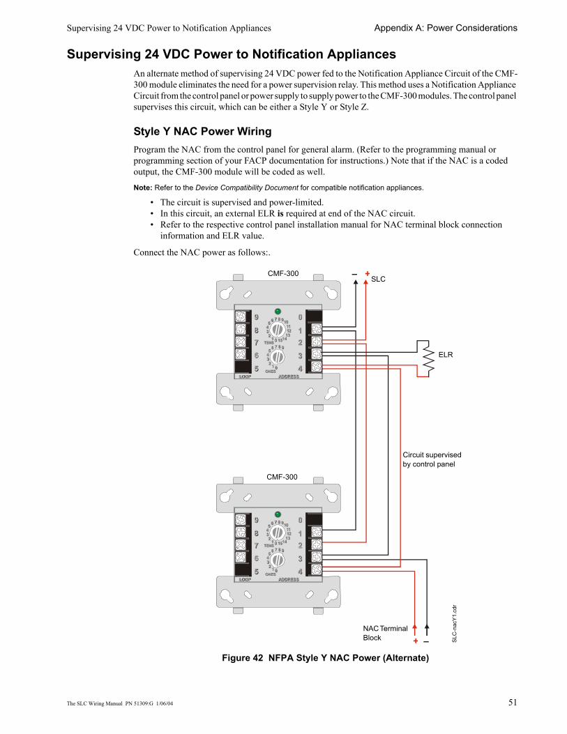
Supervising 24 VDC Power to Notification Appliances Appendix A: Power Considerations
The SLC Wiring Manual PN 51309:G 1/06/04 51
Supervising 24 VDC Power to Notification AppliancesAn alternate method of supervising 24 VDC power fed to the Notification Appliance Circuit of the CMF-300 module eliminates the need for a power supervision relay. This method uses a Notification Appliance Circuit from the control panel or power supply to supply power to the CMF-300 modules. The control panel supervises this circuit, which can be either a Style Y or Style Z.
Style Y NAC Power WiringProgram the NAC from the control panel for general alarm. (Refer to the programming manual or programming section of your FACP documentation for instructions.) Note that if the NAC is a coded output, the CMF-300 module will be coded as well.
Note: Refer to the Device Compatibility Document for compatible notification appliances.
• The circuit is supervised and power-limited.• In this circuit, an external ELR is required at end of the NAC circuit. • Refer to the respective control panel installation manual for NAC terminal block connection
information and ELR value.
Connect the NAC power as follows:.
Figure 42 NFPA Style Y NAC Power (Alternate)
8 910111213
1415012345 6 7
8 9
012345 6 7
TENS
ONESLOOPLOOP ADDRESSADDRESS
89
765
98765
0
12344321
0
TENS
ONES
8 9
012345 6 7
8 910111213
1415012345 6 7
8 910111213
1415012345 6 7
8 9
012345 6 7
TENS
ONESLOOPLOOP ADDRESSADDRESS
89
765
98765
0
12344321
0
TENS
ONES
8 9
012345 6 7
8 910111213
1415012345 6 7
– +
+ –
CMF-300SLC
SLC
-nac
Y1.c
dr
ELR
NAC Terminal Block
CMF-300
Circuit supervised by control panel
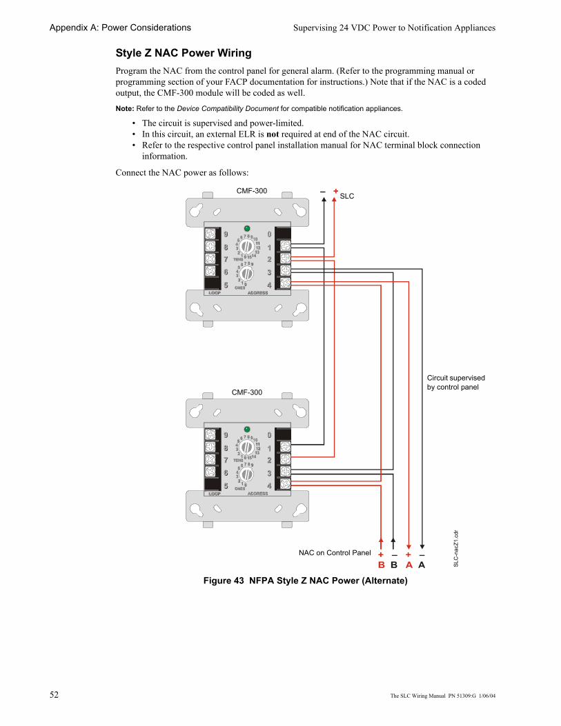
Appendix A: Power Considerations Supervising 24 VDC Power to Notification Appliances
52 The SLC Wiring Manual PN 51309:G 1/06/04
Style Z NAC Power WiringProgram the NAC from the control panel for general alarm. (Refer to the programming manual or programming section of your FACP documentation for instructions.) Note that if the NAC is a coded output, the CMF-300 module will be coded as well.
Note: Refer to the Device Compatibility Document for compatible notification appliances.
• The circuit is supervised and power-limited.• In this circuit, an external ELR is not required at end of the NAC circuit.• Refer to the respective control panel installation manual for NAC terminal block connection
information.
Connect the NAC power as follows:
Figure 43 NFPA Style Z NAC Power (Alternate)
8 910111213
1415012345 6 7
8 9
012345 6 7
TENS
ONESLOOPLOOP ADDRESSADDRESS
89
765
98765
0
12344321
0
TENS
ONES
8 9
012345 6 7
8 910111213
1415012345 6 7
8 910111213
1415012345 6 7
8 9
012345 6 7
TENS
ONESLOOPLOOP ADDRESSADDRESS
89
765
98765
0
12344321
0
TENS
ONES
8 9
012345 6 7
8 910111213
1415012345 6 7
– + SLCCMF-300
SLC
-nac
Z1.c
dr
NAC on Control Panel
Circuit supervised by control panel
CMF-300

The SLC Wiring Manual PN 51309:G 1/06/04 53
Appendix B: Surge Suppression
IntroductionThere are three (3) primary surge protectors that are approved for use with the MS-9200, MS-9200UD and MS-9600.
• DTK-2LVLP-F Diversified Technology Group, Inc. 1720 Starkey Rd. Largo, FL 33771 (727) 812-5000
• SLCP-030 EDCO 1805 N.E. 19th Ave. Ocala, FL 34470 (352) 732-3029• PLP-42N Northern Technologies, Inc. 23123 E. Madison Ave. Liberty Lake, WA 99019 (800)
727-9119Note: For detailed information refer to the installation documentation supplied with the unit.
One primary surge protector must be used with each SLC wiring pair whenever SLC wiring runs outside the building.
• Install primary protection only as shown in this document.• Refer to NEC Article 800 and local building code requirements.
Additional primary surge suppressors may be added as required by the NEC. Add these additional suppressors in series with the SLC wiring at the building entry/exit.
Wiring connected to the surge suppressor output must remain within the building while wiring connected to the surge suppressor input may be routed outside the building as shown below.
InstallationMounting of the surge suppressor must be inside the FACP enclosure or in a separate enclosure listed for fire protective signaling use.
• Locate on an available stud and secure with nut.• Unit is connected in series with the SLC Loop to protect the Control Panel.• Provide a common ground to eliminate the possibility of a differential in ground potentials.
FACP
Surge Suppressor
Building #2 Building #1
PP
P P S
SP = PrimaryS = Secondary
SLC
-ssb
uild
1.cd
r
Primary devices meet NEC Requirements
Secondary devices meet UL1459 (UL1950)

Appendix B: Surge Suppression Installation
54 The SLC Wiring Manual PN 51309:G 1/06/04
Wiring Diagram for MS-9200
DTK-2LVLP-F Connections
PLP-42N Connections
Note: Use 12AWG (3.25mm2) to 18AWG (0.75mm2) wire with crimp-on connectors to connect the unit’s ground terminal to equipment ground. Wire length must be minimized to provide best protection.
SLCP-030 Connections
IN
IN
OUT
OUT
2LVLP-F
2LVLP-F
–+
SLC Loop
SLC Terminal Block
SLC
-lvlp
1.cd
r
Optional 4-wire Return LoopStyle 6 (Class A)
–+
INPU
T
OU
TPU
T
PLP-42N
L1
L2
L
3
L4
L1
L2
L
3
L4
GR
ND
INPU
T
OU
TPU
T
PLP-42N
L1
L2
L
3
L4
L1
L2
L
3
L4
GR
ND
SLC
-plp
n1.c
drSLC Loop
SLC Terminal Block
Optional 4-wire Return LoopStyle 6 (Class A)
IN
IN
OUT
OUT
SLCP-30
SLCP-30
+–
SLC
-slc
p1.c
dr
SLC Terminal Block
SLC Loop
Optional 4-wire Return LoopStyle 6 (Class A)

Installation Appendix B: Surge Suppression
The SLC Wiring Manual PN 51309:G 1/06/04 55
Wiring Diagram for MS-9600 and MS-9200UD
DTK-2LVLP-F Connections
PLP-42N Connections
Note: Use 12AWG (3.25mm2) to 18AWG (0.75mm2) wire with crimp-on connectors to connect the unit’s ground terminal to equipment ground. Wire length must be minimized to provide best protection.
SLCP-030 Connections
IN
IN
OUT
OUT
2LVLP-F
2LVLP-F
+–
SLC Loop
SLC Terminal Block
SLC
-lvlp
4.cd
r
Optional 4-wire Return LoopStyle 6 (Class A)
+–
INPU
T
OU
TPU
T
PLP-42N
L1
L2
L
3
L4
L1
L2
L
3
L4
GR
ND
INPU
T
OU
TPU
T
PLP-42N
L1
L2
L
3
L4
L1
L2
L
3
L4
GR
ND
SLC
-plp
n4.c
drSLC Loop
SLC Terminal Block
Optional 4-wire Return LoopStyle 6 (Class A)
IN
IN
OUT
OUT
SLCP-30
SLCP-30
–+
SLC
-slc
p4.c
dr
SLC Terminal BlockSLC Loop
Optional 4-wire Return LoopStyle 6 (Class A)

Index
56 The SLC Wiring Manual PN 51309:G 1/06/04
IndexNumerics24 VDC detectors 4924 VDC NAC power 3724 VDC power
alternate method of supervising51
MS-9200, MS-9600 16
AAD350 Detector 9, 47AD355 9address capacity 20addressable
devices 20modules 8, 24
Alarm Verification 47Authority Having Jurisdiction 11auxiliary devices 8
BB224 RB Relay Detector Base 47B224 RI Isolator Detector Base 47B350LP Detector Base 47B501BH Sounder Detector Base 47Bases, detector 47BG-12LX 9, 48building entry/exit 53
Ccircuit fault 8CLIP Mode 9close nippled conduit 23CMF-300 Control Module 8CMF-300 module 37, 38, 39, 51,52
installation 37wiring 38
CMF-300-6address disabling 40
CMF-300-6 Control Module 8CMF-300-6 module 37, 42, 43
address setting 40circuit board 41installation 40short circuit protection 40Style selection 40wiring 42
coded output 51, 52common ground 53conduit, close nippled 23connectors, crimp-on 54, 55Control Modules 8control panel 8CP350 Detector 9, 47
CP355 9CRF-300 module, wiring of 44CRF-300 Relay Module 8CRF-300-6 module
address disabling 46address setting 46circuit board 45wiring 46
CRF-300-6 module, wiring of 44CRF-300-6 Relay Module 8
DD350P Detector 9D350RP Detector 9DC resistance 13, 14detector base, wiring of 47Detector Bases 47detector bases 47detectors 47
listing 9devices
addressable 20auxiliary 8supervised 50
document sources 10drain wire 15dry-contact 8DTK-2LVLP-F 53
Eelectrical interference 12ELR, external 51End-of-Line Resistor 38, 42
Ffault 11, 22fault condition 20Fault Isolator Module 20Fire alarm service 27foil 15Form C relay 47Form-C contacts 44Form-C relays 8four-wire configuration 39, 43
Ggeneral alarm 51, 52ground terminal 54, 55
HH350 Detector 9, 47H350R Detector 9H355 9H355HT 9
H355R 9Heat Detector 47
II300 20I300 Isolator Module 8Initiating Device Circuits 24, 28,30, 32integral relay 20Ionization Detector 47Isolator Module 8
how it works 20wiring of 20
isolator modules 22, 23
Kkey-lock reset 48
LLEDs 47local building code 53loop resistance 13, 14loops 14
MMDF-300 Dual module 8, 24, 32MDF-300 module
wiring 32metal conduit 15, 22minimum resistance 49MMF-300 module 8, 24, 28, 29MMF-300-10 Module 8MMF-300-10 module 25, 30, 31
wiring 30, 31MMF-301 module 8, 24MMF-302 module 8, 24, 33, 34
wiring 33MMF-302-6 Interface Module 8MMF-302-6 module 26, 35, 36
wiring 35module circuits 24modules
addressable 8control 8isolator 8monitor 8relay 8
Monitor Modules 8, 24Multicriteria Detector 47Multi-Point Module 27
NNAC power 37, 52
wiring of 51

Index
The SLC Wiring Manual PN 51309:G 1/06/04 57
NAC terminal block 51NAC wiring 37NEC Article 800 53NFPA Style 4
wiring of 18with I300 21
NFPA Style 6wiring of 19with I300 22
NFPA Style 7 20with isolator modules 23
NFPA Style BIDC wiring 28, 30, 32, 33, 35
NFPA Style DIDC wiring 29, 31, 34, 36
NFPA Style Y 37wiring of 38, 42
NFPA Style Z 37wiring of 39, 43
Nonresettable power 16normally closed contacts 50Notification Appliance Circuit 8, 51notification appliances 50
Pperformance 11Photoelectric Detector 47PLP-42N 53power run 49, 50power supervision relay 38, 39, 42,43, 50power-limited 51proper gauge wire 49Pull Station 9pull station 23
wiring of 48
RRA400Z 47rate of rise 9ratings, relay contact 37, 44relay contact ratings 37, 44Relay Module 8relays
Form-C 8Remote LED Annunciator 47Resettable power 16resistance 13, 14rotary switches 27, 31, 32, 33, 34,35, 36, 47
SSD350 Detector 9, 47SD350T Detector 9SD355 9SD355T 9sensing circuit, thermistor 9
short circuit 20Signaling Line Circuit 8Single Point Module 27SLC address, setting of 27, 47SLC connections 16SLC terminal block 15SLC wiring 28, 29, 30, 31, 32, 33,34, 35, 36SLCP-030 53Smoke Detectors 47Sprinkler supervision 27supervised 51
circuit 50devices 50
supplying power 49suppressors, surge 53surge protector 11, 53switching 37
Tterminal block, NAC 52terminal blocks 16termination of shield 15Thermal Detector 47thermistor sensing circuit 9trouble conditions 11, 20T-tapping 13, 18, 19, 22, 23twisted-pair shielded wiring 12two-wire configuration 38, 42
UUnregulated power 16
Vverification cycle 47
WWaterflow alarm service, automaticand manual 27wire length 13, 14wire size 12wiring
NACs 37of an isolator module 20
wiring pair 53wiring requirements 12wiring style requirements 11

58 The SLC Wiring Manual PN 51309:G 1/06/04
Notes

LimWarLg.p65 01/10/2000
The manufacturer warrants its products to be free from defects in materials and workmanshipfor eighteen (18) months from the date of manufacture, under normal use and service. Productsare date-stamped at time of manufacture. The sole and exclusive obligation of the manufactureris to repair or replace, at its option, free of charge for parts and labor, any part which isdefective in materials or workmanship under normal use and service. For products not underthe manufacturer's date-stamp control, the warranty is eighteen (18) months from date oforiginal purchase by the manufacturer's distributor unless the installation instructions or catalogsets forth a shorter period, in which case the shorter period shall apply. This warranty is voidif the product is altered, repaired, or serviced by anyone other than the manufacturer or itsauthorized distributors, or if there is a failure to maintain the products and systems in whichthey operate in a proper and workable manner. In case of defect, secure a Return MaterialAuthorization form from our customer service department. Return product, transportationprepaid, to the manufacturer.
This writing constitutes the only warranty made by this manufacturer with respect to itsproducts. The manufacturer does not represent that its products will prevent any loss by fireor otherwise, or that its products will in all cases provide the protection for which they areinstalled or intended. Buyer acknowledges that the manufacturer is not an insurer and assumesno risk for loss or damages or the cost of any inconvenience, transportation, damage, misuse,abuse, accident, or similar incident.
THE MANUFACTURER GIVES NO WARRANTY, EXPRESSED OR IMPLIED, OFMERCHANTABILITY, FITNESS FOR ANY PARTICULAR PURPOSE, OR OTHERWISEWHICH EXTEND BEYOND THE DESCRIPTION ON THE FACE HEREOF. UNDERNO CIRCUMSTANCES SHALL THE MANUFACTURER BE LIABLE FOR ANY LOSSOF OR DAMAGE TO PROPERTY, DIRECT, INCIDENTAL, OR CONSEQUENTIAL,ARISING OUT OF THE USE OF, OR INABILITY TO USE THE MANUFACTURER'SPRODUCTS. FURTHERMORE, THE MANUFACTURER SHALL NOT BE LIABLE FORANY PERSONAL INJURY OR DEATH WHICH MAY ARISE IN THE COURSE OF, ORAS A RESULT OF, PERSONAL, COMMERCIAL, OR INDUSTRIAL USE OF ITSPRODUCTS.
This warranty replaces all previous warranties and is the only warranty made by themanufacturer. No increase or alteration, written or verbal, of the obligation of this warrantyis authorized.
Limited Warranty

World HeadquartersOne Fire-Lite Place, Northford, CT 06472-1653 USA
203-484-7161 • Fax 203-484-7118www.firelite.com