Embed Size (px)
Citation preview
iCIRRUS Contract No. 644526 1 Jan 2015 – 31 Dec 2017
This project has received funding from the European Union’s Horizon 2020 research and innovation programme under grant agreement No 644526 (iCIRRUS)
intelligent Converged network consolIdating Radio and optical access aRound USer equipment
DELIVERABLE: D5.2
Tools, scenarios and results for testing analysis methods for validation test
Contract number: 644526
Project acronym: iCIRRUS
Project title: Intelligent converged network consolidating radio and optical access around user equipment
Project duration: 1 January 2015 – 31 December 2017
Coordinator: Nathan Gomes, University of Kent, Canterbury, UK
Deliverable Number: D5.2
Type: Report
Dissemination level Public
Date submitted: 25-04-2017
Editors: Sabine Delaitre, Silvia Blasco (WT)
Authors / contributors (contributing partners)
P. Asimakopoulos, N. Gomes, H. Zhu (UniKent), L. Fernandez del Rosal, M. Hinrichs (HHI), P. Ritoša (TS), D. Münch, J.-P. Elbers (ADVA), C. Magurawalage, K. Wang (UEssex), S. Delaitre, M. Castaño Torres, S. Blasco (WT)
Internal reviewers N. Gomes (UniKent), M. Georgiades (PTEL)
iCIRRUS Contract No. 644526 1 Jan 2015 – 31 Dec 2017
This project has received funding from the European Union’s Horizon 2020 research and innovation programme under grant agreement No 644526 (iCIRRUS)
Document history
Version 0.0 Document creation, Test template and examples (WT)
17/06/2016
Version 0.1 WT and TS contributions 12/08/2016 Version 0.2 UEssex, UniKent, ADVA, HHI,
IAF contributions 28/11/2016
Version 0.3 Discussion on D5.2 approach 25/01/2017 Version 0.4 Updated contributions from
ADVA, IAF 31/01/2017
Version 0.5 Updated contributions from WT, TS, Orange
08/02/2017
Version 0.6 Updated contributions from UEssex, UniKent, HHI
14/02/2017
Version 0.7 Timeline, Alignment with D5.1. Ready for internal review
06/03/2017
Version 0.8 Modifications and Improvement of sections 2 and 3, particularly following 2nd Annual Review recommendations
30/03/2017
Version 0.9 Conclusions, Abstract and Executive summary – internal review
10/04/2017
Version 1.0 Final version 25/04/2017
iCIRRUS Contract No. 644526 1 Jan 2015 – 31 Dec 2017
This project has received funding from the European Union’s Horizon 2020 research and innovation programme under grant agreement No 644526 (iCIRRUS)
Contents Document history _____________________________________________________________ 2
Executive summary ___________________________________________________________ 4
Abstract_____________________________________________________________________ 5
Index of terms _______________________________________________________________ 6
Index of figures _______________________________________________________________ 7
Index of tables _______________________________________________________________ 7
1 Introduction _____________________________________________________________ 8 1.1 Methodology ________________________________________________________________ 8 1.2 Structure of the document______________________________________________________ 9
2 Presentation of Test cases: collaboration and validation areas ____________________ 10 2.1 Real-time fronthaul platform using 60 GHz wireless ________________________________ 11 2.2 CPRI over ETH transport test and verification in live LTE network _____________________ 14 2.3 Open Air Interface (OAI) based Radio over Ethernet ________________________________ 17 2.4 Testbed integration with sync-enabled aggregator/switch ___________________________ 19 2.5 Ethernet-based fronthaul network ______________________________________________ 21 2.6 ETH transport lab tests of new higher-layer functional split fronthaul __________________ 23 2.7 Video Streaming in C-RAN with Mobile Cloud _____________________________________ 27 2.8 Mobile Task offloading in C-RAN with Mobile Cloud ________________________________ 29 2.9 Computational tasks in the MCN for Unified Communications use case _________________ 30 2.10 D2D Communication _________________________________________________________ 33
3 Timeline ________________________________________________________________ 35 3.1 Timeline description of the tests ________________________________________________ 35 3.2 Timeline description of the final showcase demonstrator ____________________________ 39
4 Conclusions _____________________________________________________________ 39
5 Annex __________________________________________________________________ 41 5.1 HHI: test description related to test 1 ____________________________________________ 41 5.2 Telecom Slovenia: tests description related to Test 2 _______________________________ 44 5.3 University of Kent: tests description related to Tests 3 and 4 _________________________ 45 5.4 ADVA: test description related to Test 5 __________________________________________ 49 5.5 Orange: tests description related to Test 6 ________________________________________ 51 5.6 University of Essex: tests description related to Tests 7 and 8 ________________________ 52 5.7 Wellness Telecom: test description related to Tests 7, 8 and 9 _______________________ 56 5.8 UKent: test description related to Test 10 ________________________________________ 58
iCIRRUS Contract No. 644526 1 Jan 2015 – 31 Dec 2017
I
This project has received funding from the European Union’s Horizon 2020 research and innovation programme under grant agreement No 644526 (iCIRRUS) 4
Executive summary
D5.2 is the second deliverable planned for WP5, focusing on the Integration and Validation of iCIRRUS project technologies, and eventually providing a show case of technologies and solutions. The deliverable is entitled, “Tools, scenarios and results analysis methods for validation test” and is the result of task T5.2 “Planning of test cases”, performed in close collaboration with T5.1, “Identification of test platforms and module development”; it aims to describe the tests to be performed in order to evaluate the correct integration of iCIRRUS components which would include the expected results of the test cases.
The deliverable describes the definition of the test cases to be performed, the tools necessary and how test procedures are to be followed once the different modules that comprise the iCIRRUS technological advances have been developed and are working properly. The tests described are aimed at proving the proper integration of the research and development output of WP3 and WP4 towards a final demonstrator.
D5.2 is a relevant input for subsequent tasks in WP5, namely T5.3 “Integration and tests”, focused on the execution of tests according to the procedures, tools and planning presented in D5.1 and D5.2, and T5.4, “Validation of use cases and results analysis”.
iCIRRUS Contract No. 644526 1 Jan 2015 – 31 Dec 2017
I
This project has received funding from the European Union’s Horizon 2020 research and innovation programme under grant agreement No 644526 (iCIRRUS) 5
Abstract
This document reports all work carried out under T5.2 “Planning of test cases”. The main goal of T5.2 is the planning of tests for the demonstration and validation of the project´s results, by means of a progressive integration. Thus, a detailed definition of tests is necessary, in order to detect interdependencies, the need for resources and the need for inputs from other tests. This task requires the cooperation of all iCIRRUS partners, achieving a complete overview of the testing procedure. A common template has been used by all partners in this task, in order to reach an agreement about the definition of test cases required in order to advance in the integration process. The result is a description of progressive integration, functional tests, with a significant demand for collaboration between partners.
The testing cases defined for iCIRRUS, namely Control plane, Transport/data plane and Mobile Cloud, have been considered, so that the set of tests presented in this document are able to depict the whole spectrum of the project. Therefore, the common aim of all tests is the validation requiring different levels or depths of integration, bringing the project closer to the validation of the underlying innovations that have arisen.
In the first section, a brief introduction to the methodology applied in order to achieve a homogeneous definition of tests is presented. The complete set of integration tests is then presented, highlighting the relationship with the testbeds described in D5.1 and the innovation to be shown, according to the objectives of iCIRRUS. The deliverable presents ten (10) different validation tests; more specifically four (4) tests will help to validate the control plane, seven (7) the data / transport plane and three (3) the mobile cloud (some tests provide validation of more than one area). Next, these tests are organized in a timeline, so that their interdependencies are respected, guaranteeing the achievement of the feedback and results necessary to define and build the final scenario/demonstrator, according to the project planning.
The detailed descriptions of the tests are included in the annex for further information, according to the specific template created for the collection process.
iCIRRUS Contract No. 644526 1 Jan 2015 – 31 Dec 2017
I
This project has received funding from the European Union’s Horizon 2020 research and innovation programme under grant agreement No 644526 (iCIRRUS) 6
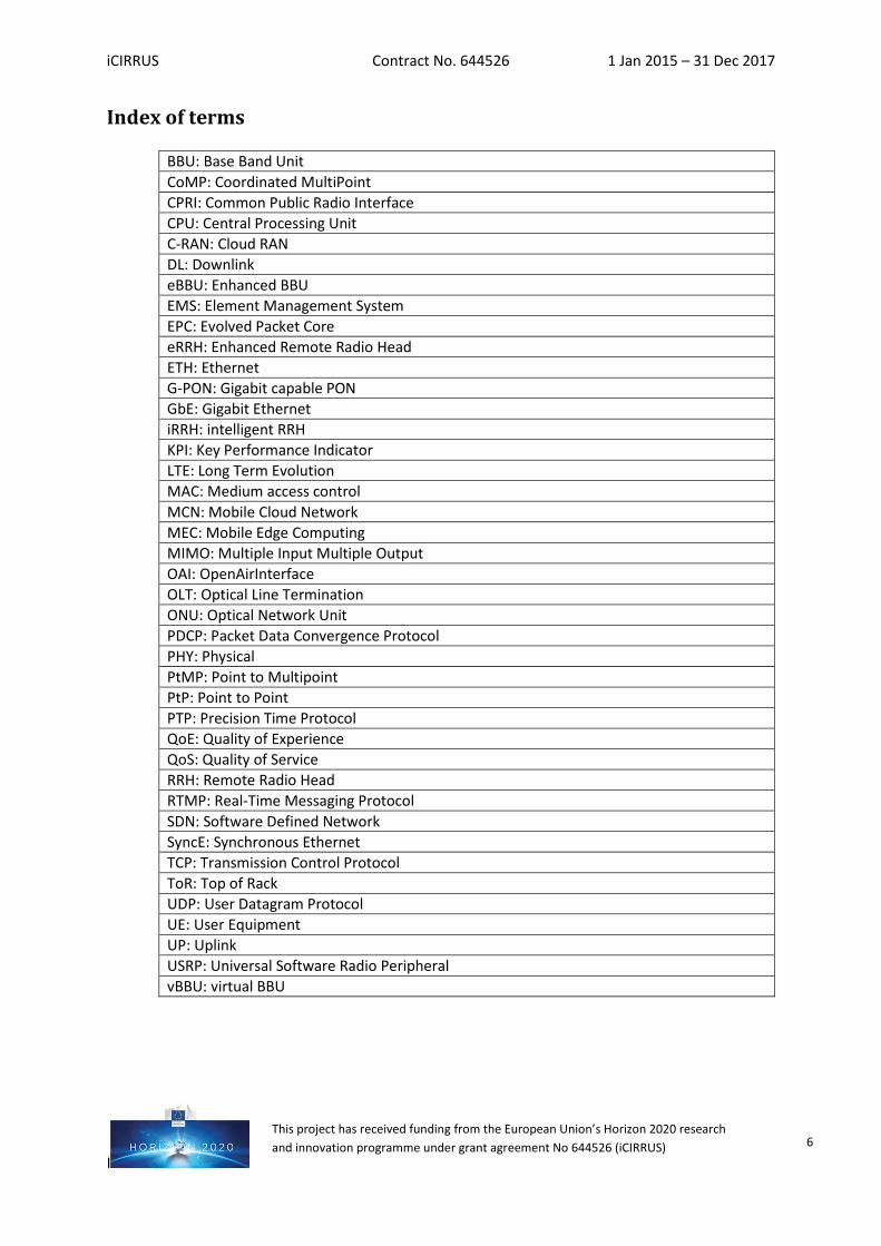
Index of terms
BBU: Base Band Unit CoMP: Coordinated MultiPoint CPRI: Common Public Radio Interface CPU: Central Processing Unit C-RAN: Cloud RAN DL: Downlink eBBU: Enhanced BBU EMS: Element Management System EPC: Evolved Packet Core eRRH: Enhanced Remote Radio Head ETH: Ethernet G-PON: Gigabit capable PON GbE: Gigabit Ethernet iRRH: intelligent RRH KPI: Key Performance Indicator LTE: Long Term Evolution MAC: Medium access control MCN: Mobile Cloud Network MEC: Mobile Edge Computing MIMO: Multiple Input Multiple Output OAI: OpenAirInterface OLT: Optical Line Termination ONU: Optical Network Unit PDCP: Packet Data Convergence Protocol PHY: Physical PtMP: Point to Multipoint PtP: Point to Point PTP: Precision Time Protocol QoE: Quality of Experience QoS: Quality of Service RRH: Remote Radio Head RTMP: Real-Time Messaging Protocol SDN: Software Defined Network SyncE: Synchronous Ethernet TCP: Transmission Control Protocol ToR: Top of Rack UDP: User Datagram Protocol UE: User Equipment UP: Uplink USRP: Universal Software Radio Peripheral vBBU: virtual BBU
iCIRRUS Contract No. 644526 1 Jan 2015 – 31 Dec 2017
I
This project has received funding from the European Union’s Horizon 2020 research and innovation programme under grant agreement No 644526 (iCIRRUS) 7
Index of figures
Figure 1: Methodology timeline in two main iterative loops for development of work undertaken in T5.2 ..... 9 Figure 2: Test setup for FPGA-platform migration for DU and RU .................................................................. 12 Figure 3: Test setup for Integration of DU, RU, UE and 60GHz ....................................................................... 13 Figure 4: Test setup for Integration of application/demo use case ................................................................ 13 Figure 5: Testbed Setup ‘CPRI over Ethernet .................................................................................................. 14 Figure 6: CPRI KPI measured and reported by the system .............................................................................. 16 Figure 7: OAI-based Radio over Ethernet testbed set-up ............................................................................... 19 Figure 8: Testbed Setup integration with sync-enabled 10GbE aggregator/switch or SDN-enabled switch’ ... 21 Figure 9: Setup 10/100G aggregator test phase 2 .......................................................................................... 22 Figure 10: Experimental setup for ETH transport lab tests of new functional split fronthaul (not CPRI) ......... 24 Figure 11: Test configuration layout for test 1.X - Ethernet PtP ..................................................................... 25 Figure 12: Test configuration layout for test 1.X, PON (FTTx) ......................................................................... 26 Figure 13: A new RAN architecture based on Ethernet fronthaul ................................................................... 27 Figure 14: Video Streaming in C-RAN with mobile cloud ................................................................................ 27 Figure 15: Mobile Cloud in C-RAN .................................................................................................................. 28 Figure 16: Videoconference scenario in UC with n participants...................................................................... 30 Figure 17: Videoconference scenario in UC with 2 participants ...................................................................... 32
Index of tables
Table 1: Test template for detailed definition .................................................................................................. 9 Table 2: Relationship of testing cases and tests ............................................................................................. 11 Table 3: Tentative testing timeline ................................................................................................................ 38
iCIRRUS Contract No. 644526 1 Jan 2015 – 31 Dec 2017
I
This project has received funding from the European Union’s Horizon 2020 research and innovation programme under grant agreement No 644526 (iCIRRUS) 8
1 Introduction
Deliverable D5.2, “Tools, scenarios and results analysis methods for validation test”, is aimed at describing the tests to be performed in order to evaluate the correct integration of iCIRRUS components, including the expected results. This document is focused on the Integration and Validation of the iCIRRUS technology, by means of a complete definition and planning of tests aimed at progressively performing the integration of different modules, the validation of their operational performance and developments towards a final demonstration scenario.
This deliverable is the result of task T5.2, “Planning of test cases”, performed in close collaboration with task T5.1, “Identification of test platforms and module development”. The document has been built by means of the definition of the tests to be performed, once the different modules that comprise the technology advancements arising in the iCIRRUS project have been developed and are working properly. Thus, the tests described are aimed at proving the proper integration between different partners towards a final, joint scenario. Also, special attention is given to the correct sequence and relationship between different tests, as numerous interdependencies are found. Considering this, it is important to properly plan tests, defining a timeline aimed at guaranteeing the availability of the knowledge and experience required to build the final scenario to demonstrate the results of iCIRRUS as a whole.
1.1 Methodology
The methodology has been organised around two main iterative loops and aims at defining different tests to be carried out indicating the action, the status of the infrastructure and to which modules involve, the expected results and the timeline in which must be done. The main challenging objective of our methodology is to achieve a homogeneous definition of tests, covering all the spectrum of the iCIRRUS project, from FPGA-platform to mobile cloud network. The different involved partners performed iterations to provide the final test descriptions presented in this document by using a detailed test template designed by the consortium. This template (see Table 1) is the main tool of this methodology, allowing a common, coherent point of view for the different activities involved in the project and aiding mutual understanding. This is of relevance due to the variety of technologies, methodologies and philosophies involved in iCIRRUS, from electronics and RF to software issues, and to the interaction necessary between control, data and mobile cloud planes. However, for further details regarding the test environment and the individual tests, a complete description of this testbed is available in D5.1.
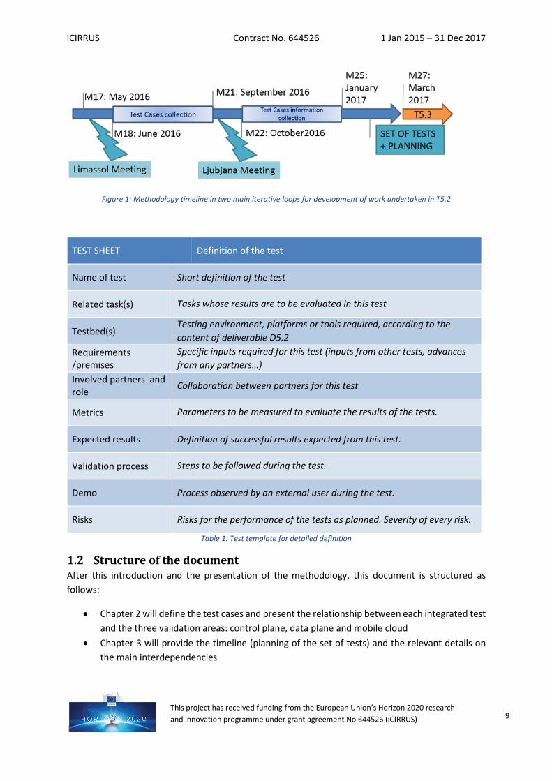
Using this methodology, a close collaboration of all partners involved in T5.2 has been achieved, so that the advances in WP3 and WP4 have been properly reflected in this document, with these tests aimed at demonstrating the results of both work packages. The progressive definition of test and testbeds (see also deliverable D5.1) has taken several months, according to the project planning and as shown in Figure 1.
iCIRRUS Contract No. 644526 1 Jan 2015 – 31 Dec 2017
I
This project has received funding from the European Union’s Horizon 2020 research and innovation programme under grant agreement No 644526 (iCIRRUS) 9
Figure 1: Methodology timeline in two main iterative loops for development of work undertaken in T5.2
Table 1: Test template for detailed definition
1.2 Structure of the document After this introduction and the presentation of the methodology, this document is structured as follows:
• Chapter 2 will define the test cases and present the relationship between each integrated test and the three validation areas: control plane, data plane and mobile cloud
• Chapter 3 will provide the timeline (planning of the set of tests) and the relevant details on the main interdependencies
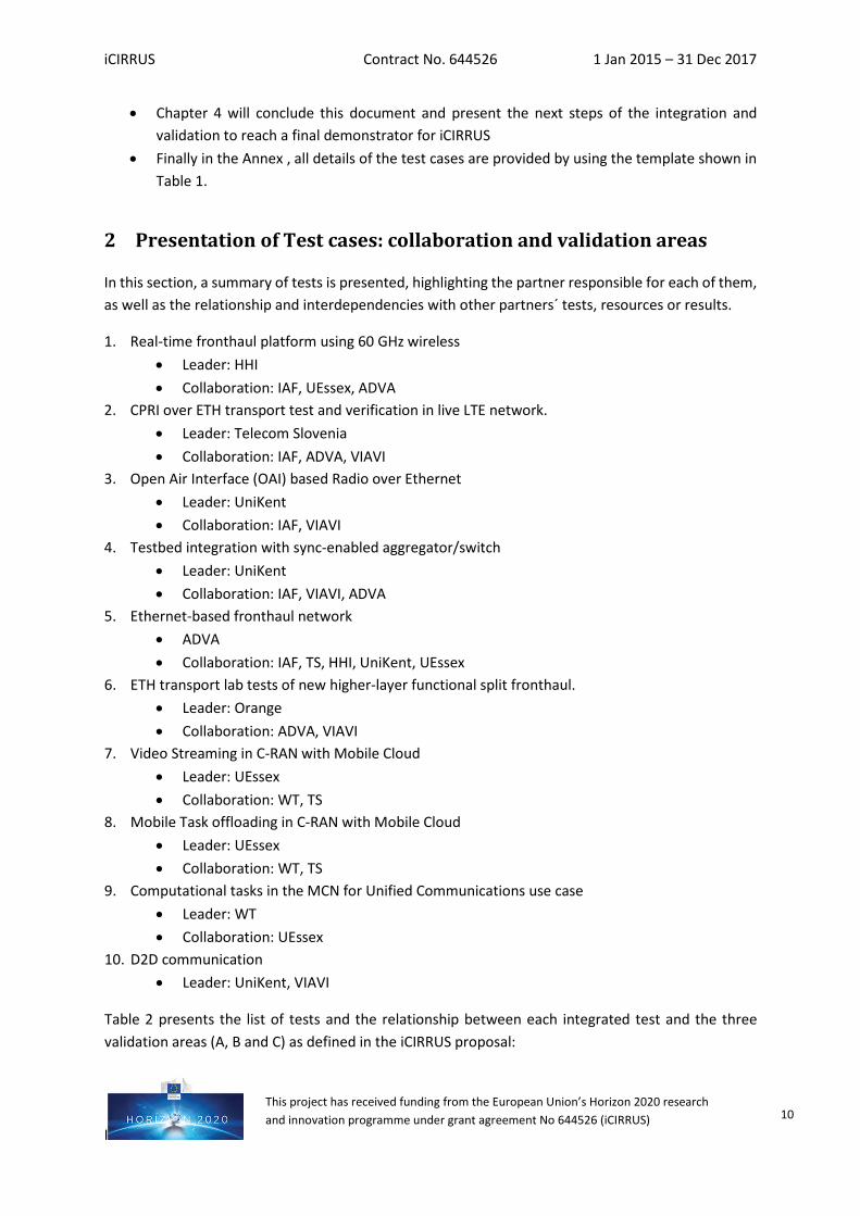
TEST SHEET Definition of the test
Name of test Short definition of the test
Related task(s) Tasks whose results are to be evaluated in this test
Testbed(s) Testing environment, platforms or tools required, according to the content of deliverable D5.2
Requirements /premises
Specific inputs required for this test (inputs from other tests, advances from any partners…)
Involved partners and role Collaboration between partners for this test
Metrics Parameters to be measured to evaluate the results of the tests.
Expected results Definition of successful results expected from this test.
Validation process Steps to be followed during the test.
Demo Process observed by an external user during the test.
Risks Risks for the performance of the tests as planned. Severity of every risk.
iCIRRUS Contract No. 644526 1 Jan 2015 – 31 Dec 2017
I
This project has received funding from the European Union’s Horizon 2020 research and innovation programme under grant agreement No 644526 (iCIRRUS) 10
• Chapter 4 will conclude this document and present the next steps of the integration and validation to reach a final demonstrator for iCIRRUS
• Finally in the Annex , all details of the test cases are provided by using the template shown in Table 1.
2 Presentation of Test cases: collaboration and validation areas
In this section, a summary of tests is presented, highlighting the partner responsible for each of them, as well as the relationship and interdependencies with other partners´ tests, resources or results.
1. Real-time fronthaul platform using 60 GHz wireless • Leader: HHI • Collaboration: IAF, UEssex, ADVA
2. CPRI over ETH transport test and verification in live LTE network. • Leader: Telecom Slovenia • Collaboration: IAF, ADVA, VIAVI
3. Open Air Interface (OAI) based Radio over Ethernet • Leader: UniKent • Collaboration: IAF, VIAVI
4. Testbed integration with sync-enabled aggregator/switch • Leader: UniKent • Collaboration: IAF, VIAVI, ADVA
5. Ethernet-based fronthaul network • ADVA • Collaboration: IAF, TS, HHI, UniKent, UEssex
6. ETH transport lab tests of new higher-layer functional split fronthaul. • Leader: Orange • Collaboration: ADVA, VIAVI
7. Video Streaming in C-RAN with Mobile Cloud • Leader: UEssex • Collaboration: WT, TS
8. Mobile Task offloading in C-RAN with Mobile Cloud • Leader: UEssex • Collaboration: WT, TS
9. Computational tasks in the MCN for Unified Communications use case • Leader: WT • Collaboration: UEssex
10. D2D communication • Leader: UniKent, VIAVI
Table 2 presents the list of tests and the relationship between each integrated test and the three validation areas (A, B and C) as defined in the iCIRRUS proposal:
iCIRRUS Contract No. 644526 1 Jan 2015 – 31 Dec 2017
I
This project has received funding from the European Union’s Horizon 2020 research and innovation programme under grant agreement No 644526 (iCIRRUS) 11
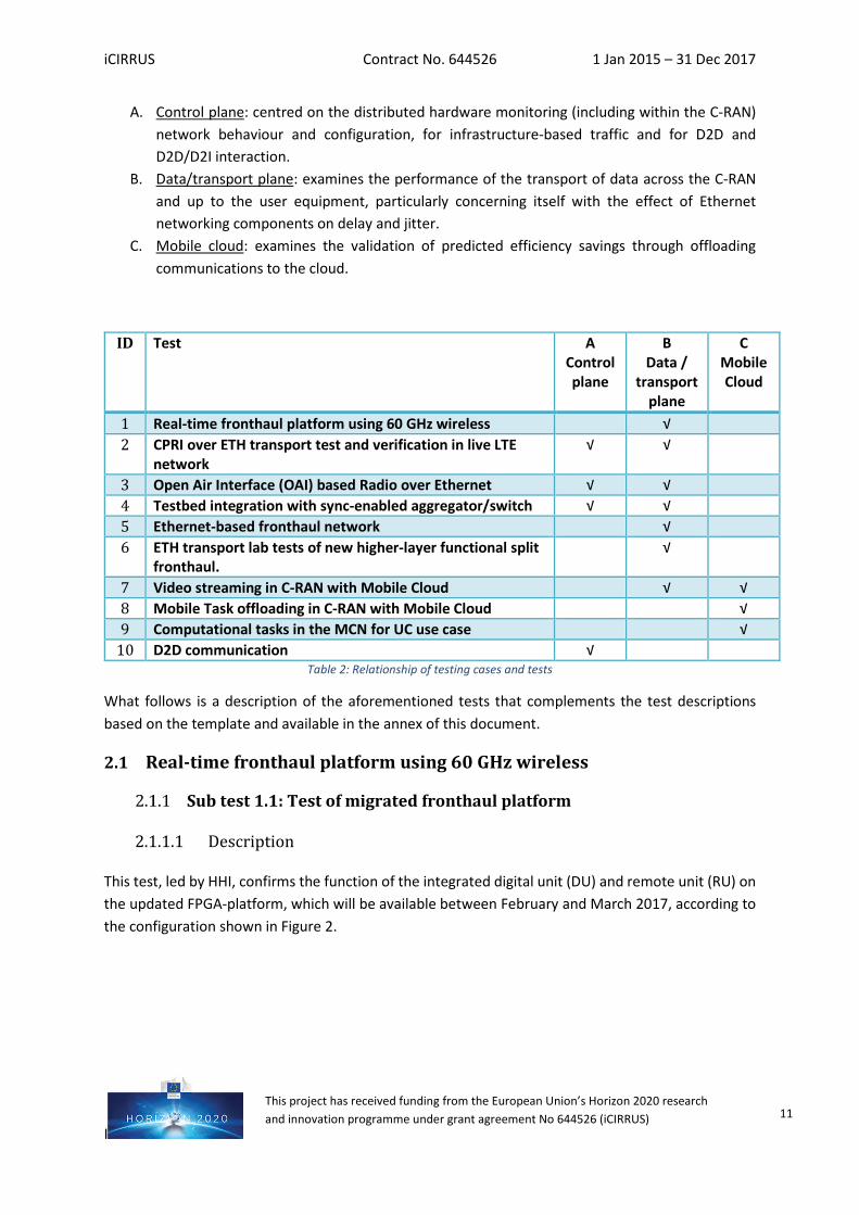
A. Control plane: centred on the distributed hardware monitoring (including within the C-RAN) network behaviour and configuration, for infrastructure-based traffic and for D2D and D2D/D2I interaction.
B. Data/transport plane: examines the performance of the transport of data across the C-RAN and up to the user equipment, particularly concerning itself with the effect of Ethernet networking components on delay and jitter.
C. Mobile cloud: examines the validation of predicted efficiency savings through offloading communications to the cloud.
ID Test A Control plane
B Data /
transport plane
C Mobile Cloud
1 Real-time fronthaul platform using 60 GHz wireless √ 2 CPRI over ETH transport test and verification in live LTE
network √ √
3 Open Air Interface (OAI) based Radio over Ethernet √ √ 4 Testbed integration with sync-enabled aggregator/switch √ √ 5 Ethernet-based fronthaul network √ 6 ETH transport lab tests of new higher-layer functional split
fronthaul. √
7 Video streaming in C-RAN with Mobile Cloud √ √ 8 Mobile Task offloading in C-RAN with Mobile Cloud √ 9 Computational tasks in the MCN for UC use case √
10 D2D communication √ Table 2: Relationship of testing cases and tests
What follows is a description of the aforementioned tests that complements the test descriptions based on the template and available in the annex of this document.
2.1 Real-time fronthaul platform using 60 GHz wireless
Sub test 1.1: Test of migrated fronthaul platform
2.1.1.1 Description
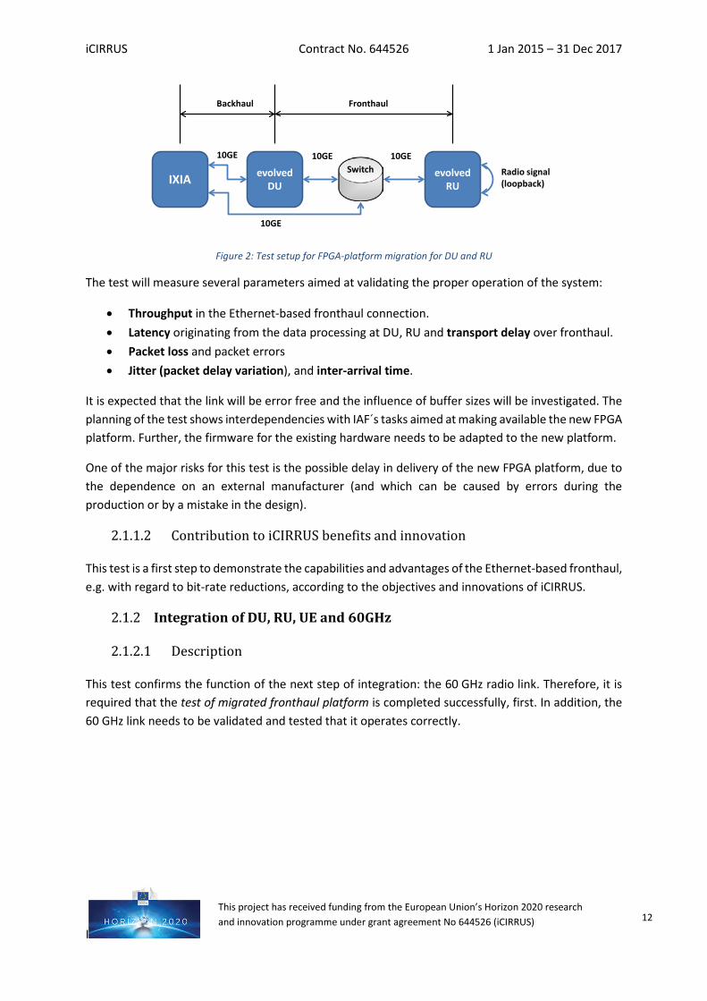
This test, led by HHI, confirms the function of the integrated digital unit (DU) and remote unit (RU) on the updated FPGA-platform, which will be available between February and March 2017, according to the configuration shown in Figure 2.
iCIRRUS Contract No. 644526 1 Jan 2015 – 31 Dec 2017
I
This project has received funding from the European Union’s Horizon 2020 research and innovation programme under grant agreement No 644526 (iCIRRUS) 12
Figure 2: Test setup for FPGA-platform migration for DU and RU
The test will measure several parameters aimed at validating the proper operation of the system:
• Throughput in the Ethernet-based fronthaul connection. • Latency originating from the data processing at DU, RU and transport delay over fronthaul. • Packet loss and packet errors • Jitter (packet delay variation), and inter-arrival time.
It is expected that the link will be error free and the influence of buffer sizes will be investigated. The planning of the test shows interdependencies with IAF´s tasks aimed at making available the new FPGA platform. Further, the firmware for the existing hardware needs to be adapted to the new platform.
One of the major risks for this test is the possible delay in delivery of the new FPGA platform, due to the dependence on an external manufacturer (and which can be caused by errors during the production or by a mistake in the design).
2.1.1.2 Contribution to iCIRRUS benefits and innovation
This test is a first step to demonstrate the capabilities and advantages of the Ethernet-based fronthaul, e.g. with regard to bit-rate reductions, according to the objectives and innovations of iCIRRUS.
Integration of DU, RU, UE and 60GHz
2.1.2.1 Description
This test confirms the function of the next step of integration: the 60 GHz radio link. Therefore, it is required that the test of migrated fronthaul platform is completed successfully, first. In addition, the 60 GHz link needs to be validated and tested that it operates correctly.
IXIA evolvedDU
evolvedRU
10GE
10GE
10GE 10GE
Radio signal(loopback)
Backhaul Fronthaul
Switch
iCIRRUS Contract No. 644526 1 Jan 2015 – 31 Dec 2017
I
This project has received funding from the European Union’s Horizon 2020 research and innovation programme under grant agreement No 644526 (iCIRRUS) 13
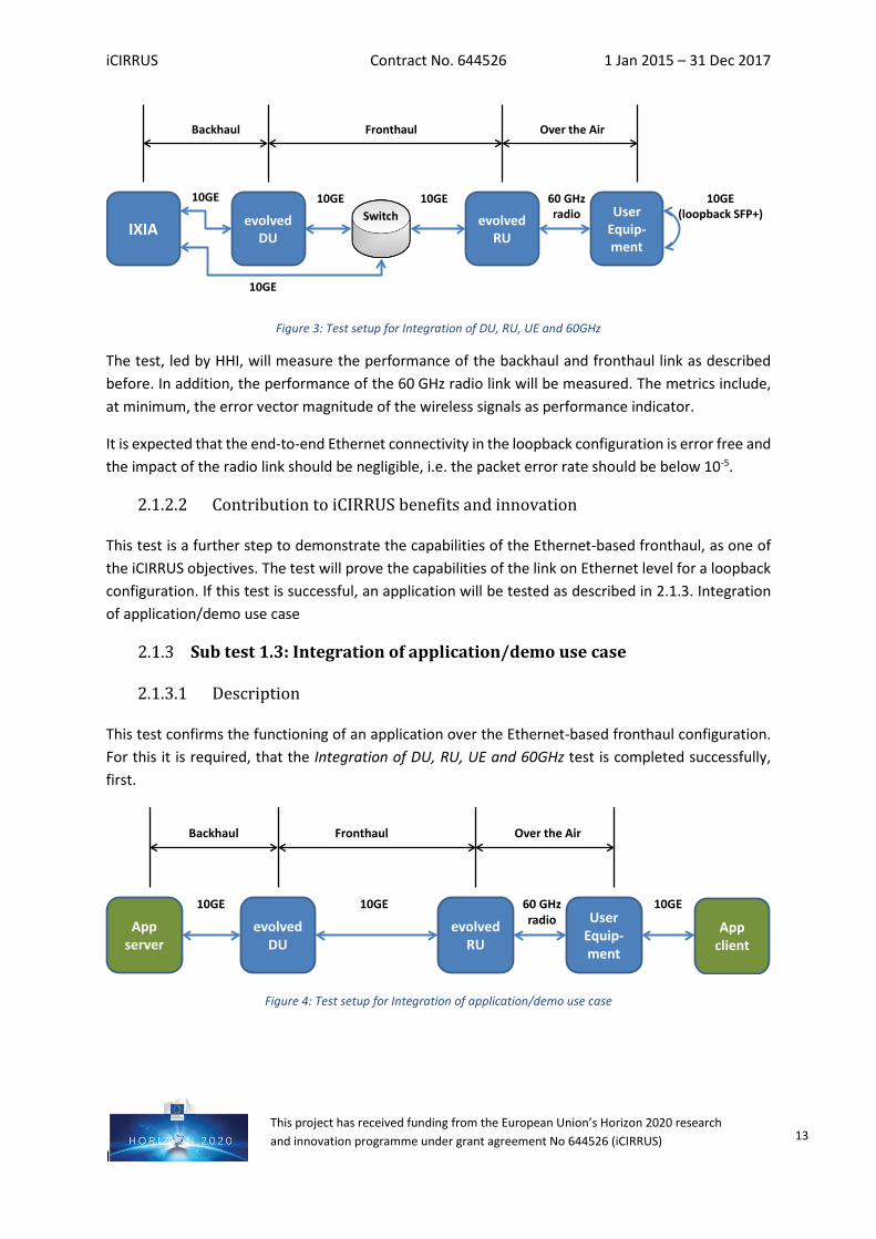
Figure 3: Test setup for Integration of DU, RU, UE and 60GHz
The test, led by HHI, will measure the performance of the backhaul and fronthaul link as described before. In addition, the performance of the 60 GHz radio link will be measured. The metrics include, at minimum, the error vector magnitude of the wireless signals as performance indicator.
It is expected that the end-to-end Ethernet connectivity in the loopback configuration is error free and the impact of the radio link should be negligible, i.e. the packet error rate should be below 10-5.
2.1.2.2 Contribution to iCIRRUS benefits and innovation
This test is a further step to demonstrate the capabilities of the Ethernet-based fronthaul, as one of the iCIRRUS objectives. The test will prove the capabilities of the link on Ethernet level for a loopback configuration. If this test is successful, an application will be tested as described in 2.1.3. Integration of application/demo use case
Sub test 1.3: Integration of application/demo use case
2.1.3.1 Description
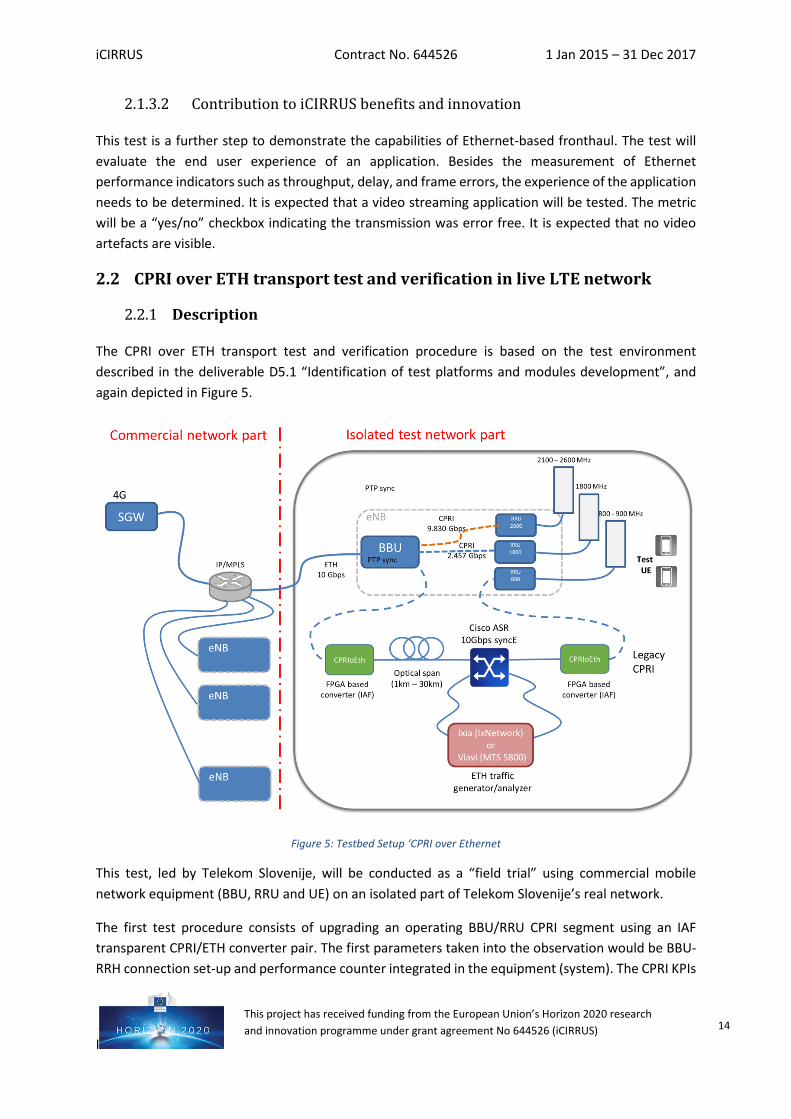
This test confirms the functioning of an application over the Ethernet-based fronthaul configuration. For this it is required, that the Integration of DU, RU, UE and 60GHz test is completed successfully, first.
Figure 4: Test setup for Integration of application/demo use case
IXIA evolvedDU
evolvedRU
10GE
10GE
10GE 10GE
Over the AirBackhaul Fronthaul
Switch UserEquip-ment
60 GHzradio
10GE(loopback SFP+)
evolvedDU
evolvedRU
10GE10GE
Over the AirBackhaul Fronthaul
UserEquip-ment
60 GHzradioApp
serverApp
client
10GE
iCIRRUS Contract No. 644526 1 Jan 2015 – 31 Dec 2017
I
This project has received funding from the European Union’s Horizon 2020 research and innovation programme under grant agreement No 644526 (iCIRRUS) 14
2.1.3.2 Contribution to iCIRRUS benefits and innovation
This test is a further step to demonstrate the capabilities of Ethernet-based fronthaul. The test will evaluate the end user experience of an application. Besides the measurement of Ethernet performance indicators such as throughput, delay, and frame errors, the experience of the application needs to be determined. It is expected that a video streaming application will be tested. The metric will be a “yes/no” checkbox indicating the transmission was error free. It is expected that no video artefacts are visible.
2.2 CPRI over ETH transport test and verification in live LTE network
Description
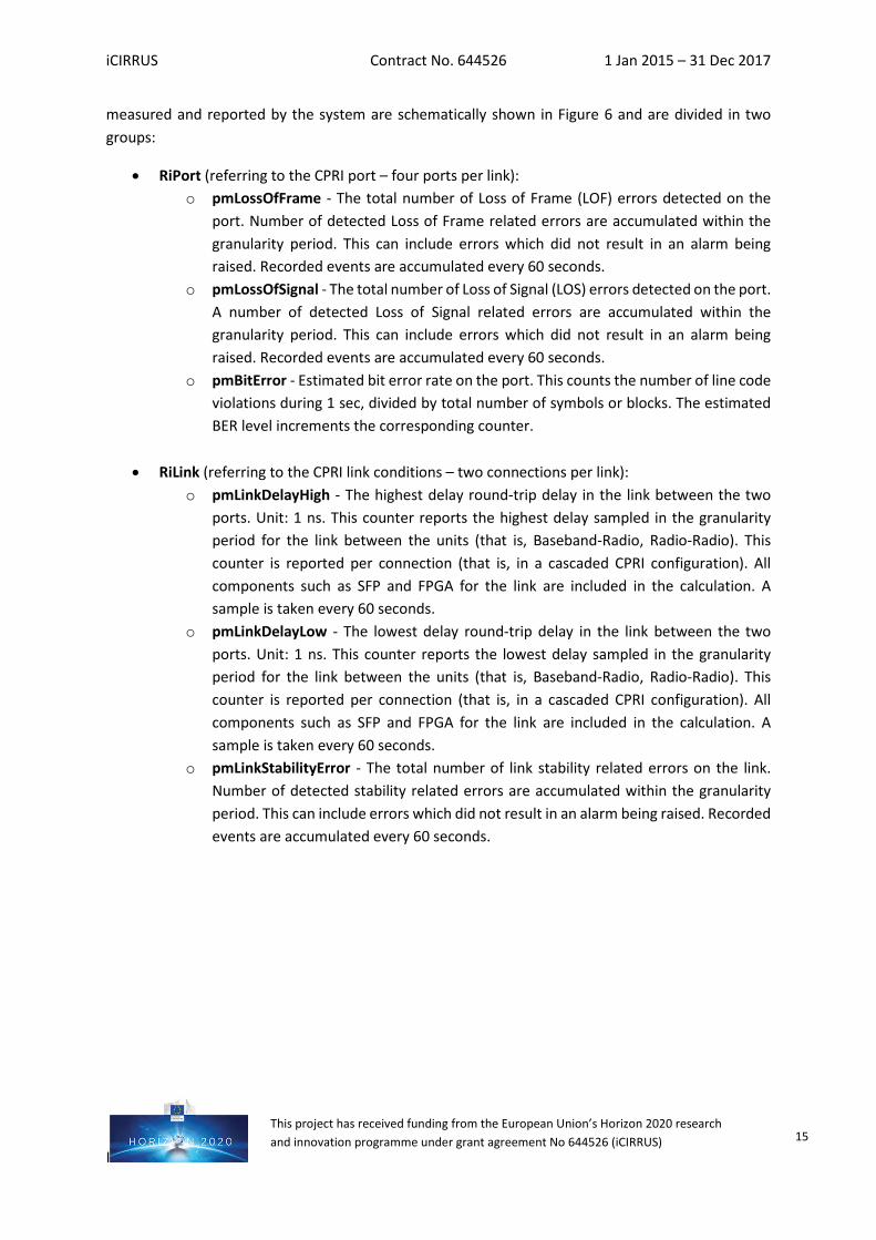
The CPRI over ETH transport test and verification procedure is based on the test environment described in the deliverable D5.1 “Identification of test platforms and modules development”, and again depicted in Figure 5.
Figure 5: Testbed Setup ‘CPRI over Ethernet
This test, led by Telekom Slovenije, will be conducted as a “field trial” using commercial mobile network equipment (BBU, RRU and UE) on an isolated part of Telekom Slovenije’s real network.
The first test procedure consists of upgrading an operating BBU/RRU CPRI segment using an IAF transparent CPRI/ETH converter pair. The first parameters taken into the observation would be BBU-RRH connection set-up and performance counter integrated in the equipment (system). The CPRI KPIs
iCIRRUS Contract No. 644526 1 Jan 2015 – 31 Dec 2017
I
This project has received funding from the European Union’s Horizon 2020 research and innovation programme under grant agreement No 644526 (iCIRRUS) 15
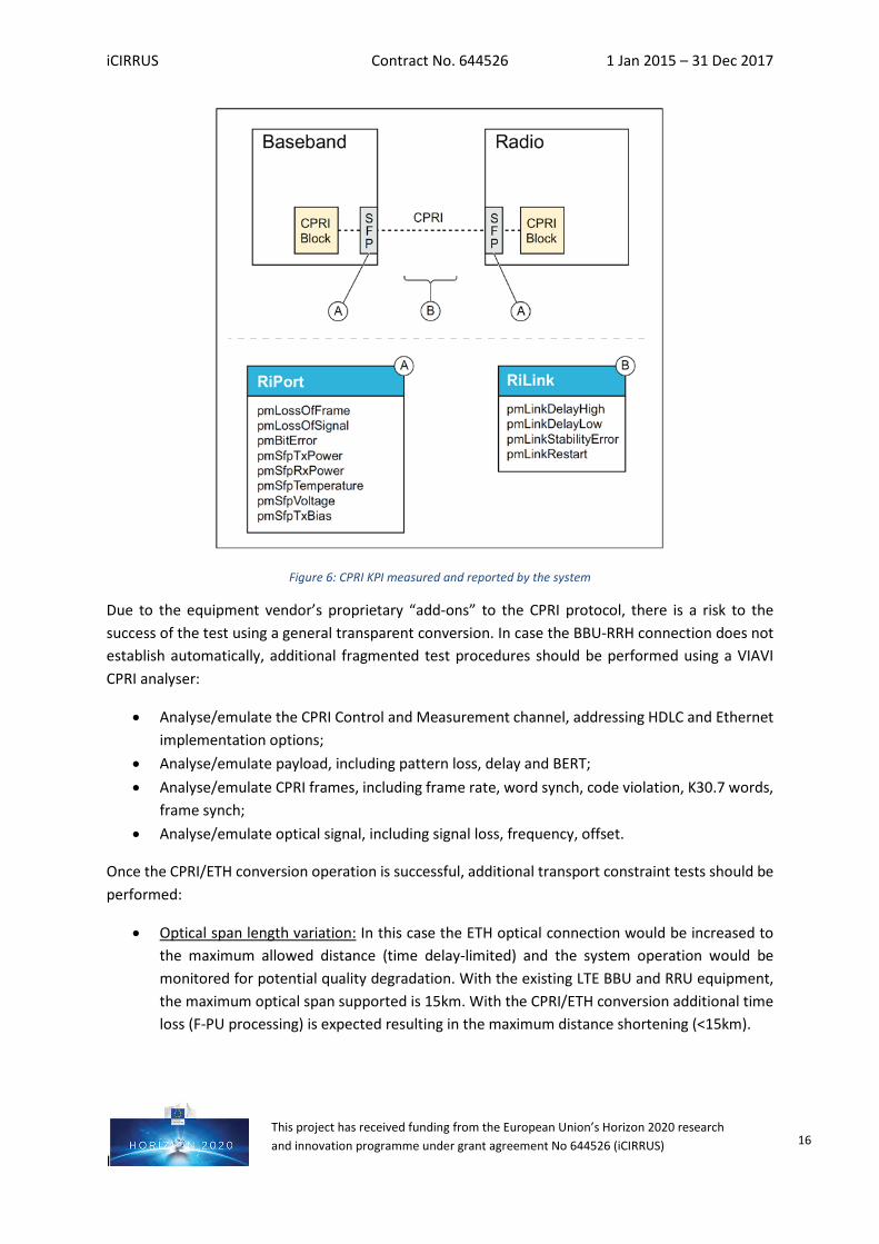
measured and reported by the system are schematically shown in Figure 6 and are divided in two groups:
• RiPort (referring to the CPRI port – four ports per link): o pmLossOfFrame - The total number of Loss of Frame (LOF) errors detected on the
port. Number of detected Loss of Frame related errors are accumulated within the granularity period. This can include errors which did not result in an alarm being raised. Recorded events are accumulated every 60 seconds.
o pmLossOfSignal - The total number of Loss of Signal (LOS) errors detected on the port. A number of detected Loss of Signal related errors are accumulated within the granularity period. This can include errors which did not result in an alarm being raised. Recorded events are accumulated every 60 seconds.
o pmBitError - Estimated bit error rate on the port. This counts the number of line code violations during 1 sec, divided by total number of symbols or blocks. The estimated BER level increments the corresponding counter.
• RiLink (referring to the CPRI link conditions – two connections per link): o pmLinkDelayHigh - The highest delay round-trip delay in the link between the two
ports. Unit: 1 ns. This counter reports the highest delay sampled in the granularity period for the link between the units (that is, Baseband-Radio, Radio-Radio). This counter is reported per connection (that is, in a cascaded CPRI configuration). All components such as SFP and FPGA for the link are included in the calculation. A sample is taken every 60 seconds.
o pmLinkDelayLow - The lowest delay round-trip delay in the link between the two ports. Unit: 1 ns. This counter reports the lowest delay sampled in the granularity period for the link between the units (that is, Baseband-Radio, Radio-Radio). This counter is reported per connection (that is, in a cascaded CPRI configuration). All components such as SFP and FPGA for the link are included in the calculation. A sample is taken every 60 seconds.
o pmLinkStabilityError - The total number of link stability related errors on the link. Number of detected stability related errors are accumulated within the granularity period. This can include errors which did not result in an alarm being raised. Recorded events are accumulated every 60 seconds.
iCIRRUS Contract No. 644526 1 Jan 2015 – 31 Dec 2017
I
This project has received funding from the European Union’s Horizon 2020 research and innovation programme under grant agreement No 644526 (iCIRRUS) 16
Figure 6: CPRI KPI measured and reported by the system
Due to the equipment vendor’s proprietary “add-ons” to the CPRI protocol, there is a risk to the success of the test using a general transparent conversion. In case the BBU-RRH connection does not establish automatically, additional fragmented test procedures should be performed using a VIAVI CPRI analyser:
• Analyse/emulate the CPRI Control and Measurement channel, addressing HDLC and Ethernet implementation options;
• Analyse/emulate payload, including pattern loss, delay and BERT; • Analyse/emulate CPRI frames, including frame rate, word synch, code violation, K30.7 words,
frame synch; • Analyse/emulate optical signal, including signal loss, frequency, offset.
Once the CPRI/ETH conversion operation is successful, additional transport constraint tests should be performed:
• Optical span length variation: In this case the ETH optical connection would be increased to the maximum allowed distance (time delay-limited) and the system operation would be monitored for potential quality degradation. With the existing LTE BBU and RRU equipment, the maximum optical span supported is 15km. With the CPRI/ETH conversion additional time loss (F-PU processing) is expected resulting in the maximum distance shortening (<15km).
iCIRRUS Contract No. 644526 1 Jan 2015 – 31 Dec 2017
I
This project has received funding from the European Union’s Horizon 2020 research and innovation programme under grant agreement No 644526 (iCIRRUS) 17
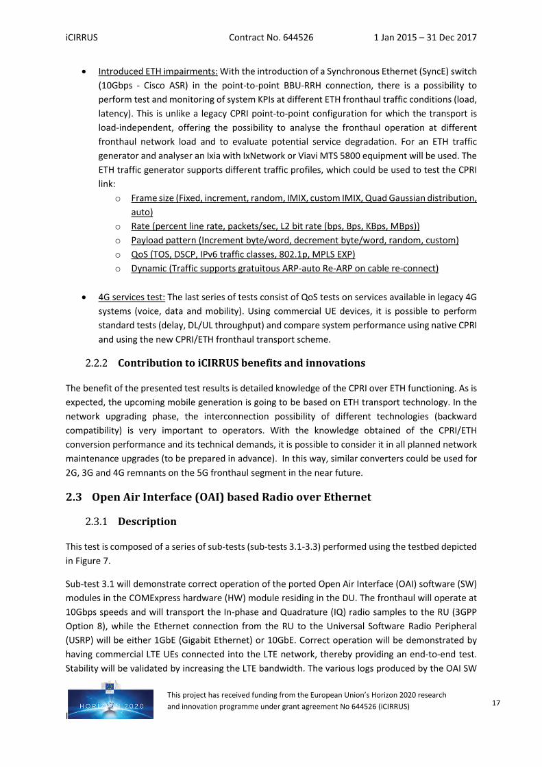
• Introduced ETH impairments: With the introduction of a Synchronous Ethernet (SyncE) switch (10Gbps - Cisco ASR) in the point-to-point BBU-RRH connection, there is a possibility to perform test and monitoring of system KPIs at different ETH fronthaul traffic conditions (load, latency). This is unlike a legacy CPRI point-to-point configuration for which the transport is load-independent, offering the possibility to analyse the fronthaul operation at different fronthaul network load and to evaluate potential service degradation. For an ETH traffic generator and analyser an Ixia with IxNetwork or Viavi MTS 5800 equipment will be used. The ETH traffic generator supports different traffic profiles, which could be used to test the CPRI link:
o Frame size (Fixed, increment, random, IMIX, custom IMIX, Quad Gaussian distribution, auto)
o Rate (percent line rate, packets/sec, L2 bit rate (bps, Bps, KBps, MBps)) o Payload pattern (Increment byte/word, decrement byte/word, random, custom) o QoS (TOS, DSCP, IPv6 traffic classes, 802.1p, MPLS EXP) o Dynamic (Traffic supports gratuitous ARP-auto Re-ARP on cable re-connect)
• 4G services test: The last series of tests consist of QoS tests on services available in legacy 4G
systems (voice, data and mobility). Using commercial UE devices, it is possible to perform standard tests (delay, DL/UL throughput) and compare system performance using native CPRI and using the new CPRI/ETH fronthaul transport scheme.
Contribution to iCIRRUS benefits and innovations
The benefit of the presented test results is detailed knowledge of the CPRI over ETH functioning. As is expected, the upcoming mobile generation is going to be based on ETH transport technology. In the network upgrading phase, the interconnection possibility of different technologies (backward compatibility) is very important to operators. With the knowledge obtained of the CPRI/ETH conversion performance and its technical demands, it is possible to consider it in all planned network maintenance upgrades (to be prepared in advance). In this way, similar converters could be used for 2G, 3G and 4G remnants on the 5G fronthaul segment in the near future.
2.3 Open Air Interface (OAI) based Radio over Ethernet
Description
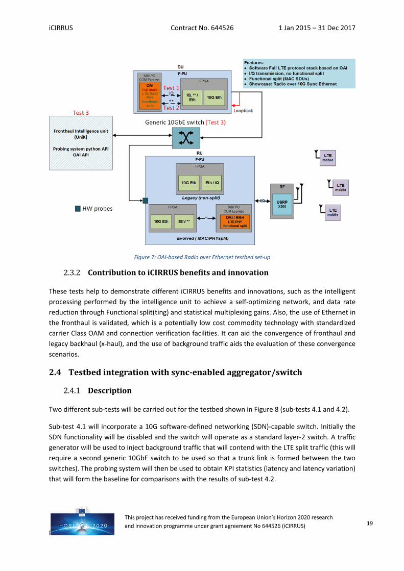
This test is composed of a series of sub-tests (sub-tests 3.1-3.3) performed using the testbed depicted in Figure 7.
Sub-test 3.1 will demonstrate correct operation of the ported Open Air Interface (OAI) software (SW) modules in the COMExpress hardware (HW) module residing in the DU. The fronthaul will operate at 10Gbps speeds and will transport the In-phase and Quadrature (IQ) radio samples to the RU (3GPP Option 8), while the Ethernet connection from the RU to the Universal Software Radio Peripheral (USRP) will be either 1GbE (Gigabit Ethernet) or 10GbE. Correct operation will be demonstrated by having commercial LTE UEs connected into the LTE network, thereby providing an end-to-end test. Stability will be validated by increasing the LTE bandwidth. The various logs produced by the OAI SW
iCIRRUS Contract No. 644526 1 Jan 2015 – 31 Dec 2017
I
This project has received funding from the European Union’s Horizon 2020 research and innovation programme under grant agreement No 644526 (iCIRRUS) 18
will be used to demonstrate seamless connectivity and help identify potential connectivity issues (limited throughput and/or increased latency) and delays in the initial attach procedure. Wireshark and Tcpdump will be used for potential networking troubleshooting. Overall performance of the system will be compared with the baseline case, which is the standard PC running OAI to USRP connection.
Sub-test 3.2 will involve the porting of the MAC/PHY split modules into the COMExpress HW modules, one residing in the DU and the other in the RU. A first test will be carried out in a loopback configuration whereby the MAC/PHY split modules will reside in the same COMExpress module. Verification will be carried out through a simulated air interface with a number of connected UEs. Increasing the number of UEs will allow testing for potential latency issues in the fronthaul SW library (buffering, networking latencies), due to the increased resource block allocations. The loopback Ethernet connection will operate at 10 Gbps. Logs will be used to monitor potential connectivity issues and/or delays in initial attach procedure and number of retransmissions. Wireshark and Tcpdump will be used for potential networking troubleshooting. The next stage of the sub-test will involve the proper end-to-end test by porting the MAC/PHY split functionality in both (separate) COMExpress modules, i.e. in the DU and RU. The network set-up in this case will be the same as in sub-test 3.1. Testing for potential delay issues will be more important here, as the functionality will be distributed across the DU and RU, which will no longer share a common memory heap. Correct operation will be verified by connecting a commercial UE and performing a stability test, the results of which will be compared to the baseline case and sub-test 3.1 results.
Logs will be used to monitor for potential connectivity issues and/or delays in the initial attach procedure and the number of retransmissions. Wireshark/Tcpdump will be used for potential networking troubleshooting. As virtual local area identifiers (VLAN IDs) and packet type headers are used to differentiate among the individual MAC/PHY split flows, performance verification is then aided by monitoring the individual flow performances.
Stability validation will be more important for sub-test 3.2 (compared to 3.1), as the resources allocated to the UE(s) will have a direct effect on the network throughput and the processing delays at the DU and RU. An additional validation step at this stage will aim at performing throughput measurements, as this will demonstrate the large throughput reduction obtained compared to the non-split case (sub-test 3.1).
Sub-test 3.3 will involve the integration of the fronthaul intelligence unit. The VIAVI 10GbE HW probes will be inserted into the network and the generated packet filter results will be used to demonstrate the ability of the intelligence unit to produce and present, in a user-friendly manner, a number of key performance indicator (KPI) statistics that will be updated dynamically (in real-time). KPIs from the probing system will include throughput and packet inter-arrival delays. Over-the-air KPIs will include per-UE throughput, uplink signal-to-noise ratio and number of hybrid automatic repeat request (HARQ) retransmissions, among others. A generic 10GbE switch will be used to connect the intelligence unit to the fronthaul.
iCIRRUS Contract No. 644526 1 Jan 2015 – 31 Dec 2017
I
This project has received funding from the European Union’s Horizon 2020 research and innovation programme under grant agreement No 644526 (iCIRRUS) 19
Figure 7: OAI-based Radio over Ethernet testbed set-up
Contribution to iCIRRUS benefits and innovation
These tests help to demonstrate different iCIRRUS benefits and innovations, such as the intelligent processing performed by the intelligence unit to achieve a self-optimizing network, and data rate reduction through Functional split(ting) and statistical multiplexing gains. Also, the use of Ethernet in the fronthaul is validated, which is a potentially low cost commodity technology with standardized carrier Class OAM and connection verification facilities. It can aid the convergence of fronthaul and legacy backhaul (x-haul), and the use of background traffic aids the evaluation of these convergence scenarios.
2.4 Testbed integration with sync-enabled aggregator/switch
Description
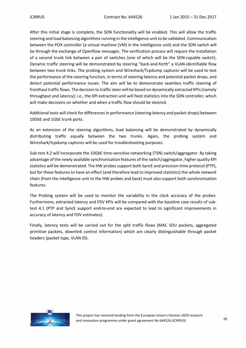
Two different sub-tests will be carried out for the testbed shown in Figure 8 (sub-tests 4.1 and 4.2).
Sub-test 4.1 will incorporate a 10G software-defined networking (SDN)-capable switch. Initially the SDN functionality will be disabled and the switch will operate as a standard layer-2 switch. A traffic generator will be used to inject background traffic that will contend with the LTE split traffic (this will require a second generic 10GbE switch to be used so that a trunk link is formed between the two switches). The probing system will then be used to obtain KPI statistics (latency and latency variation) that will form the baseline for comparisons with the results of sub-test 4.2.
iCIRRUS Contract No. 644526 1 Jan 2015 – 31 Dec 2017
I
This project has received funding from the European Union’s Horizon 2020 research and innovation programme under grant agreement No 644526 (iCIRRUS) 20
After this initial stage is complete, the SDN functionality will be enabled. This will allow the traffic steering and load balancing algorithms running in the intelligence unit to be validated. Communication between the POX controller (a virtual machine (VM) in the intelligence unit) and the SDN switch will be through the exchange of Openflow messages. The verification process will require the installation of a second trunk link between a pair of switches (one of which will be the SDN-capable switch). Dynamic traffic steering will be demonstrated by steering “back-and-forth” a VLAN-identifiable flow between two trunk links. The probing system and Wireshark/Tcpdump captures will be used to test the performance of the steering function, in terms of steering latency and potential packet drops, and detect potential performance issues. The aim will be to demonstrate seamless traffic steering of fronthaul traffic flows. The decision to traffic steer will be based on dynamically extracted KPIs (namely throughput and latency); i.e., the KPI extraction unit will feed statistics into the SDN controller, which will make decisions on whether and when a traffic flow should be steered.
Additional tests will check for differences in performance (steering latency and packet drops) between 10GbE and 1GbE trunk ports.
As an extension of the steering algorithms, load balancing will be demonstrated by dynamically distributing traffic equally between the two trunks. Again, the probing system and Wireshark/tcpdump captures will be used for troubleshooting purposes.
Sub-test 4.2 will incorporate the 10GbE time-sensitive networking (TSN) switch/aggregator. By taking advantage of the newly available synchronisation features of the switch/aggregator, higher quality KPI statistics will be demonstrated. The HW probes support both SyncE and precision-time protocol (PTP), but for these features to have an effect (and therefore lead to improved statistics) the whole network chain (from the intelligence unit to the HW probes and back) must also support both synchronisation features.
The Probing system will be used to monitor the variability in the clock accuracy of the probes. Furthermore, extracted latency and FDV KPIs will be compared with the baseline case results of sub-test 4.1 (PTP and SyncE support end-to-end are expected to lead to significant improvements in accuracy of latency and FDV estimates).
Finally, latency tests will be carried out for the split traffic flows (MAC SDU packets, aggregated primitive packets, downlink control information) which are clearly distinguishable through packet headers (packet type, VLAN ID).
iCIRRUS Contract No. 644526 1 Jan 2015 – 31 Dec 2017
I
This project has received funding from the European Union’s Horizon 2020 research and innovation programme under grant agreement No 644526 (iCIRRUS) 21
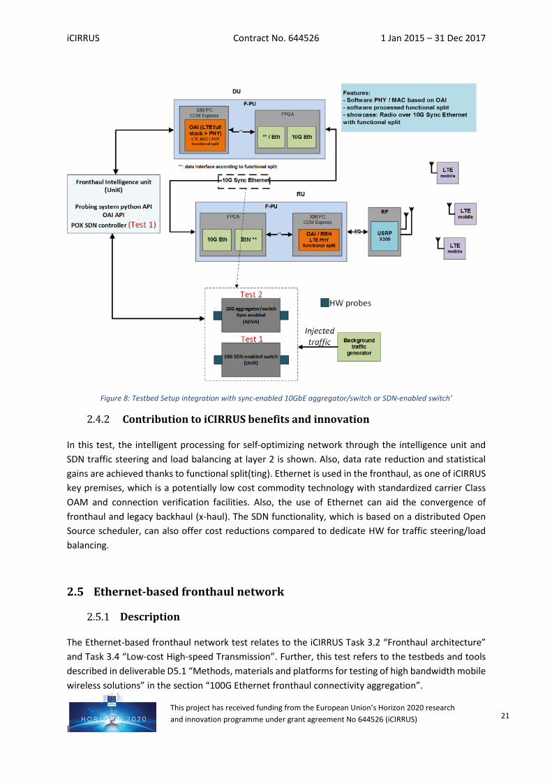
Figure 8: Testbed Setup integration with sync-enabled 10GbE aggregator/switch or SDN-enabled switch’
Contribution to iCIRRUS benefits and innovation
In this test, the intelligent processing for self-optimizing network through the intelligence unit and SDN traffic steering and load balancing at layer 2 is shown. Also, data rate reduction and statistical gains are achieved thanks to functional split(ting). Ethernet is used in the fronthaul, as one of iCIRRUS key premises, which is a potentially low cost commodity technology with standardized carrier Class OAM and connection verification facilities. Also, the use of Ethernet can aid the convergence of fronthaul and legacy backhaul (x-haul). The SDN functionality, which is based on a distributed Open Source scheduler, can also offer cost reductions compared to dedicate HW for traffic steering/load balancing.
2.5 Ethernet-based fronthaul network
Description
The Ethernet-based fronthaul network test relates to the iCIRRUS Task 3.2 “Fronthaul architecture” and Task 3.4 “Low-cost High-speed Transmission”. Further, this test refers to the testbeds and tools described in deliverable D5.1 “Methods, materials and platforms for testing of high bandwidth mobile wireless solutions” in the section “100G Ethernet fronthaul connectivity aggregation”.
iCIRRUS Contract No. 644526 1 Jan 2015 – 31 Dec 2017
I
This project has received funding from the European Union’s Horizon 2020 research and innovation programme under grant agreement No 644526 (iCIRRUS) 22
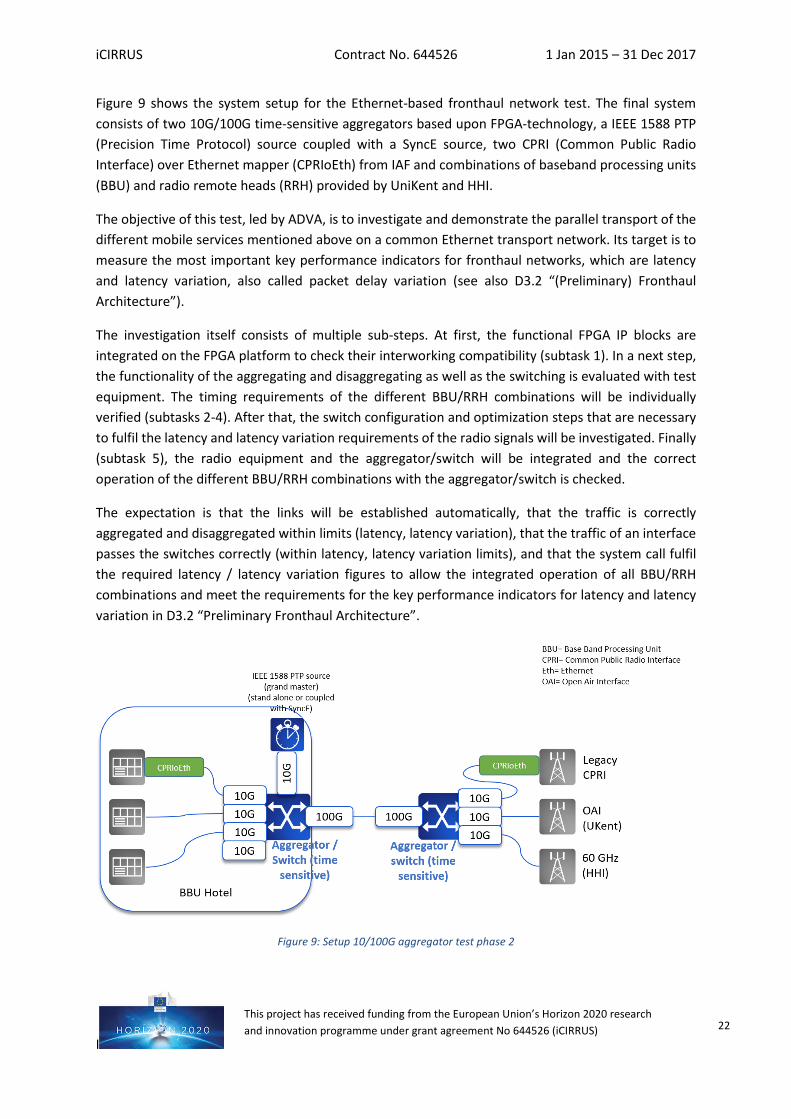
Figure 9 shows the system setup for the Ethernet-based fronthaul network test. The final system consists of two 10G/100G time-sensitive aggregators based upon FPGA-technology, a IEEE 1588 PTP (Precision Time Protocol) source coupled with a SyncE source, two CPRI (Common Public Radio Interface) over Ethernet mapper (CPRIoEth) from IAF and combinations of baseband processing units (BBU) and radio remote heads (RRH) provided by UniKent and HHI.
The objective of this test, led by ADVA, is to investigate and demonstrate the parallel transport of the different mobile services mentioned above on a common Ethernet transport network. Its target is to measure the most important key performance indicators for fronthaul networks, which are latency and latency variation, also called packet delay variation (see also D3.2 “(Preliminary) Fronthaul Architecture”).
The investigation itself consists of multiple sub-steps. At first, the functional FPGA IP blocks are integrated on the FPGA platform to check their interworking compatibility (subtask 1). In a next step, the functionality of the aggregating and disaggregating as well as the switching is evaluated with test equipment. The timing requirements of the different BBU/RRH combinations will be individually verified (subtasks 2-4). After that, the switch configuration and optimization steps that are necessary to fulfil the latency and latency variation requirements of the radio signals will be investigated. Finally (subtask 5), the radio equipment and the aggregator/switch will be integrated and the correct operation of the different BBU/RRH combinations with the aggregator/switch is checked.
The expectation is that the links will be established automatically, that the traffic is correctly aggregated and disaggregated within limits (latency, latency variation), that the traffic of an interface passes the switches correctly (within latency, latency variation limits), and that the system call fulfil the required latency / latency variation figures to allow the integrated operation of all BBU/RRH combinations and meet the requirements for the key performance indicators for latency and latency variation in D3.2 “Preliminary Fronthaul Architecture”.
Figure 9: Setup 10/100G aggregator test phase 2
iCIRRUS Contract No. 644526 1 Jan 2015 – 31 Dec 2017
I
This project has received funding from the European Union’s Horizon 2020 research and innovation programme under grant agreement No 644526 (iCIRRUS) 23
Contribution to iCIRRUS benefits and innovation
This test aims to demonstrate the following benefits of iCIRRUS:
• Demonstration that different types of next-generation fronthaul traffic as well legacy CPRI traffic can be seamlessly transported over a converged, time-sensitive Ethernet network: this is the main contribution of this test. This is addressed by investigating the latency (and latency variation) as well as the throughput.
• Low cost commodity, commercial-off-the-shelf transceiver modules are used (CFP4 / QSFP28 for 100G and SFP+ for 10G).
• High bandwidth / bitrate fronthaul demonstration, in the order of 100Gbit/s used as trunk.
2.6 ETH transport lab tests of new higher-layer functional split fronthaul
Description
Currently, optical fiber is commonly used to achieve the mobile Ethernet backhaul between the base station sites and the core network. Fronthaul is another emerging network segment considered in RAN evolution, concerning the connection from the BBU to the RRH in C-RAN context. In this case, fronthaul carries the very high bit rate digitized radio signals, according in most cases to the CPRI industry standard.
Another approach for fronthaul is now being considered by the mobile community, following the trends of RAN virtualization and very high capacity required for 5G. In fact, a number of initiatives exist presently to define new functional splits between BBU and RRH. Their main objective is to migrate, at a higher or lower proportion, some signal processing blocks from the BBU to the RRH in order to allow bit-rate reduction in the fronthaul while ensuring proper CoMP (Coordinated MultiPoint). This will also permit BBU virtualization since the high layer functions of LTE do not have real time constraints and, thus, generic servers could be used to host these functions.
This test, led by Orange, will focus on the functional split at the Packet Data Convergence Protocol (PDCP) level and the investigation in real time of the previously exposed concerns about the transported data traffic and the impact of impairments on the new fronthaul interface. The transmission is done over Point-to-Point (PtP) and Point to MultiPoint (PtMP) optical access networks.
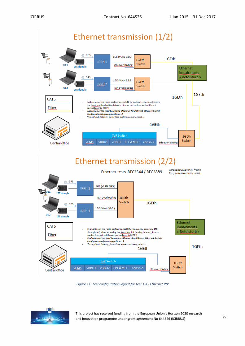
As shown in Figure 10, two solutions will be experimentally investigated for the transport of the new fronthaul interface: Ethernet PtP and PtMP with a G-PON (Gigabit capable PON) system.
iCIRRUS Contract No. 644526 1 Jan 2015 – 31 Dec 2017
I
This project has received funding from the European Union’s Horizon 2020 research and innovation programme under grant agreement No 644526 (iCIRRUS) 24
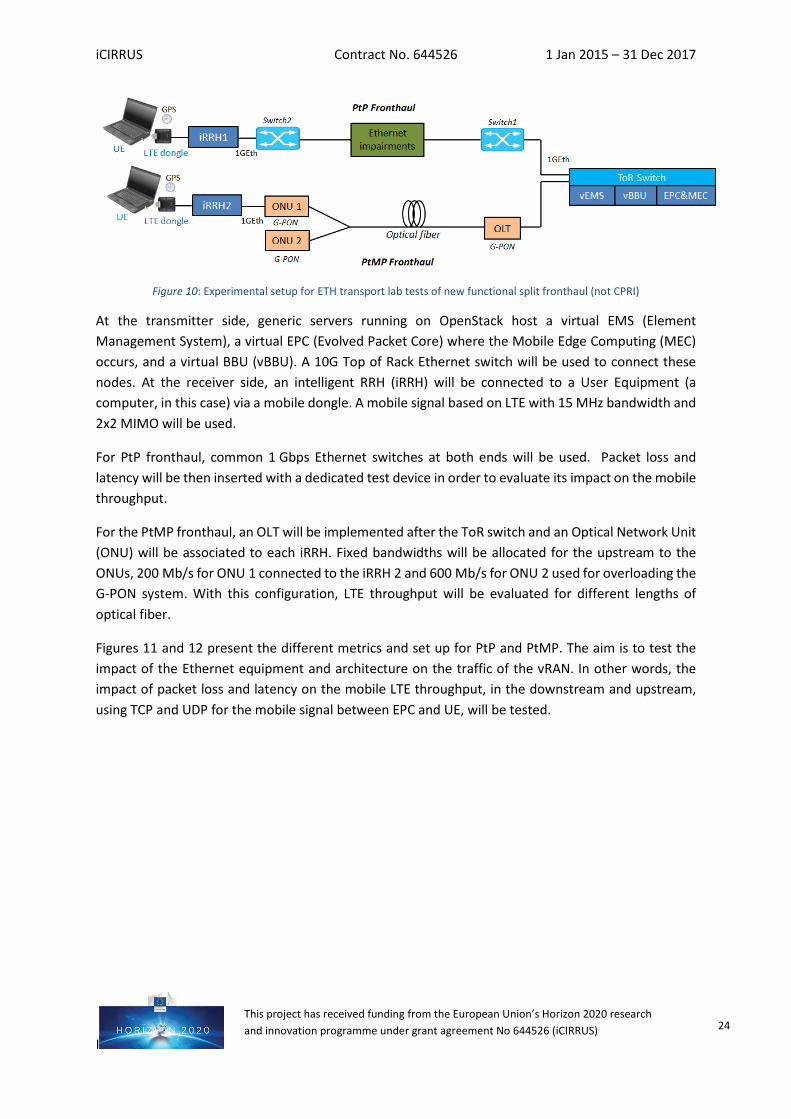
Figure 10: Experimental setup for ETH transport lab tests of new functional split fronthaul (not CPRI)
At the transmitter side, generic servers running on OpenStack host a virtual EMS (Element Management System), a virtual EPC (Evolved Packet Core) where the Mobile Edge Computing (MEC) occurs, and a virtual BBU (vBBU). A 10G Top of Rack Ethernet switch will be used to connect these nodes. At the receiver side, an intelligent RRH (iRRH) will be connected to a User Equipment (a computer, in this case) via a mobile dongle. A mobile signal based on LTE with 15 MHz bandwidth and 2x2 MIMO will be used.
For PtP fronthaul, common 1 Gbps Ethernet switches at both ends will be used. Packet loss and latency will be then inserted with a dedicated test device in order to evaluate its impact on the mobile throughput.
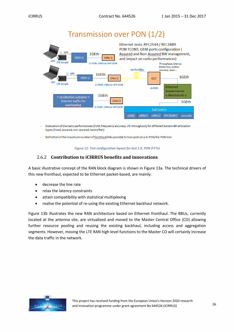
For the PtMP fronthaul, an OLT will be implemented after the ToR switch and an Optical Network Unit (ONU) will be associated to each iRRH. Fixed bandwidths will be allocated for the upstream to the ONUs, 200 Mb/s for ONU 1 connected to the iRRH 2 and 600 Mb/s for ONU 2 used for overloading the G-PON system. With this configuration, LTE throughput will be evaluated for different lengths of optical fiber.
Figures 11 and 12 present the different metrics and set up for PtP and PtMP. The aim is to test the impact of the Ethernet equipment and architecture on the traffic of the vRAN. In other words, the impact of packet loss and latency on the mobile LTE throughput, in the downstream and upstream, using TCP and UDP for the mobile signal between EPC and UE, will be tested.
iCIRRUS Contract No. 644526 1 Jan 2015 – 31 Dec 2017
I
This project has received funding from the European Union’s Horizon 2020 research and innovation programme under grant agreement No 644526 (iCIRRUS) 25
Figure 11: Test configuration layout for test 1.X - Ethernet PtP
iCIRRUS Contract No. 644526 1 Jan 2015 – 31 Dec 2017
I
This project has received funding from the European Union’s Horizon 2020 research and innovation programme under grant agreement No 644526 (iCIRRUS) 26
Figure 12: Test configuration layout for test 1.X, PON (FTTx)
Contribution to iCIRRUS benefits and innovations
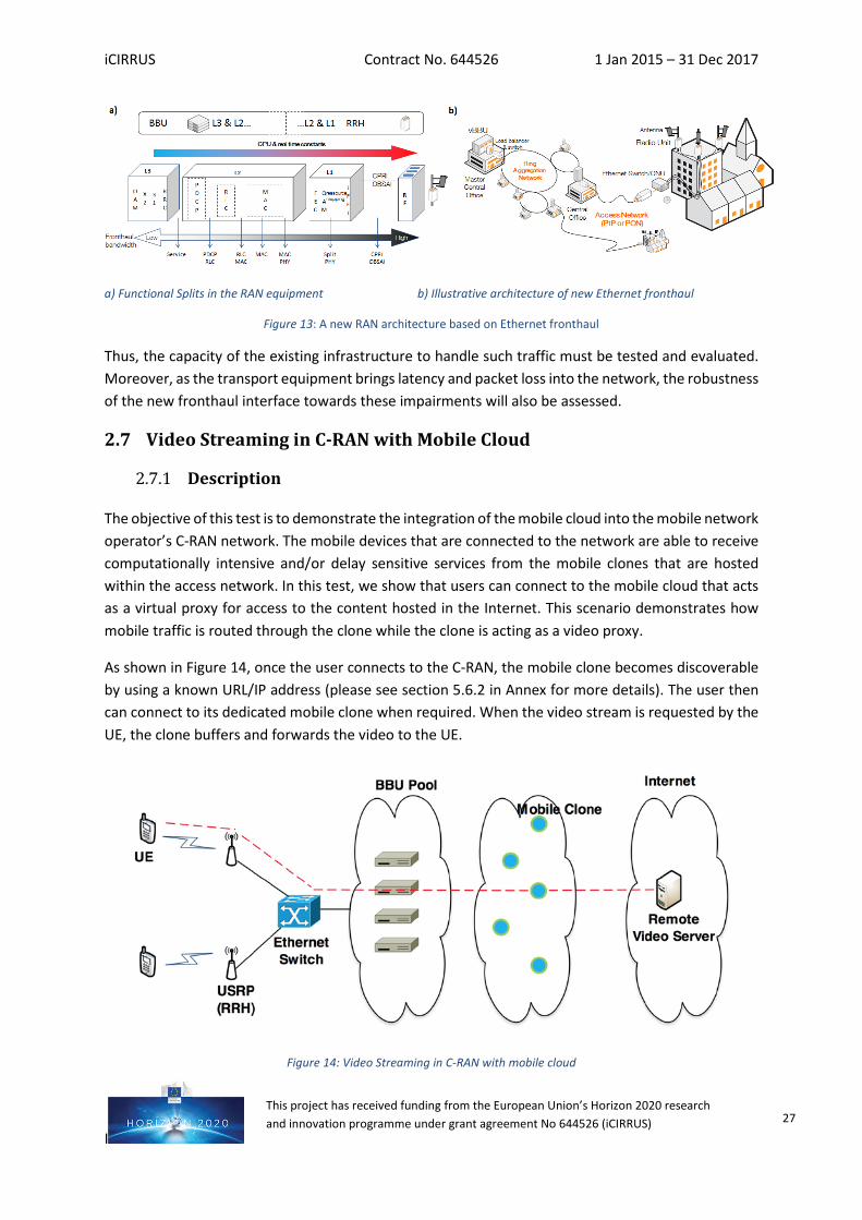
A basic illustrative concept of the RAN block diagram is shown in Figure 13a. The technical drivers of this new fronthaul, expected to be Ethernet packet-based, are mainly:
• decrease the line rate • relax the latency constraints • attain compatibility with statistical multiplexing • realise the potential of re-using the existing Ethernet backhaul network.
Figure 13b illustrates the new RAN architecture based on Ethernet fronthaul. The BBUs, currently located at the antenna site, are virtualized and moved to the Master Central Office (CO) allowing further resource pooling and reusing the existing backhaul, including access and aggregation segments. However, moving the LTE RAN high level functions to the Master CO will certainly increase the data traffic in the network.
iCIRRUS Contract No. 644526 1 Jan 2015 – 31 Dec 2017
I
This project has received funding from the European Union’s Horizon 2020 research and innovation programme under grant agreement No 644526 (iCIRRUS) 27
a) Functional Splits in the RAN equipment b) Illustrative architecture of new Ethernet fronthaul
Figure 13: A new RAN architecture based on Ethernet fronthaul
Thus, the capacity of the existing infrastructure to handle such traffic must be tested and evaluated. Moreover, as the transport equipment brings latency and packet loss into the network, the robustness of the new fronthaul interface towards these impairments will also be assessed.
2.7 Video Streaming in C-RAN with Mobile Cloud
Description
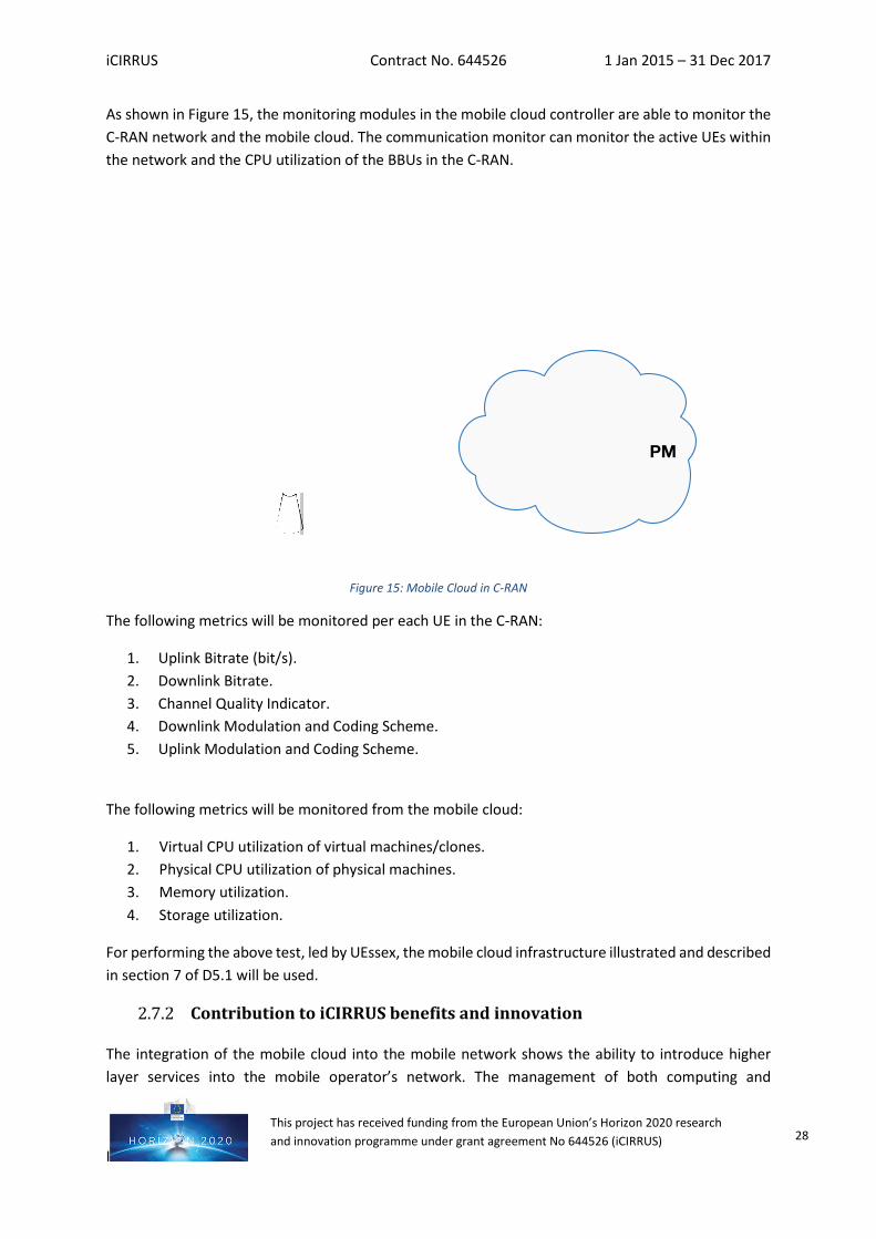
The objective of this test is to demonstrate the integration of the mobile cloud into the mobile network operator’s C-RAN network. The mobile devices that are connected to the network are able to receive computationally intensive and/or delay sensitive services from the mobile clones that are hosted within the access network. In this test, we show that users can connect to the mobile cloud that acts as a virtual proxy for access to the content hosted in the Internet. This scenario demonstrates how mobile traffic is routed through the clone while the clone is acting as a video proxy.
As shown in Figure 14, once the user connects to the C-RAN, the mobile clone becomes discoverable by using a known URL/IP address (please see section 5.6.2 in Annex for more details). The user then can connect to its dedicated mobile clone when required. When the video stream is requested by the UE, the clone buffers and forwards the video to the UE.
Figure 14: Video Streaming in C-RAN with mobile cloud
iCIRRUS Contract No. 644526 1 Jan 2015 – 31 Dec 2017
I
This project has received funding from the European Union’s Horizon 2020 research and innovation programme under grant agreement No 644526 (iCIRRUS) 28
As shown in Figure 15, the monitoring modules in the mobile cloud controller are able to monitor the C-RAN network and the mobile cloud. The communication monitor can monitor the active UEs within the network and the CPU utilization of the BBUs in the C-RAN.
Figure 15: Mobile Cloud in C-RAN
The following metrics will be monitored per each UE in the C-RAN:
1. Uplink Bitrate (bit/s). 2. Downlink Bitrate. 3. Channel Quality Indicator. 4. Downlink Modulation and Coding Scheme. 5. Uplink Modulation and Coding Scheme.
The following metrics will be monitored from the mobile cloud:
1. Virtual CPU utilization of virtual machines/clones. 2. Physical CPU utilization of physical machines. 3. Memory utilization. 4. Storage utilization.
For performing the above test, led by UEssex, the mobile cloud infrastructure illustrated and described in section 7 of D5.1 will be used.
Contribution to iCIRRUS benefits and innovation
The integration of the mobile cloud into the mobile network shows the ability to introduce higher layer services into the mobile operator’s network. The management of both computing and
iCIRRUS Contract No. 644526 1 Jan 2015 – 31 Dec 2017
I
This project has received funding from the European Union’s Horizon 2020 research and innovation programme under grant agreement No 644526 (iCIRRUS) 29
communication resources through the centralized controller is aimed at increasing efficiency in the usage of resources, both in UEs (battery, computing resources) and in the network (computing resources, bandwidth).
2.8 Mobile Task offloading in C-RAN with Mobile Cloud
Description
As thoroughly described in D4.3, the use of mobile cloud computing resources by an application in the mobile device, by commissioning processing fragments of the application to the mobile cloud, is referred to as offloading in this context. In iCIRRUS, this task-oriented offloading is considered such that the scheduling algorithm of the mobile application selects only the computation intensive part of the application to be offloaded to the mobile cloud. Offloaded tasks will be executed in mobile clones hosted in the cloud, which are VMs with the same OS of the mobile devices.
Within this test, led by UEssex, the complete process of offloading will be shown. Thus, the first step will be the connection of the UE with its clone in the MCN. The CPU intensive tasks will be sent to the clone on the fly, in order to save battery in the UE (i.e., mobile device) or to be able to perform those tasks that exceed the UE´s capabilities. Once the offloaded tasks are executed in the clone, the results are sent back to the mobile device.
During this process, changes in the utilization of CPU resources in the clone are expected. On the other hand, UL and DL network usage changes can also be observed as the tasks are being offloaded and the results are sent back to the UE. Thus, the metrics to consider in this test are network and CPU utilization of the clone.
This test will be performed using the MCN described in the section 7 of D5.1. In particular, the main elements required are a mobile device with the client side of the task offloading framework installed, and a fully configured mobile clone deployed in the MCN, with the server side of the task offloading framework installed. An OAI-based C-RAN deployment alongside the mobile cloud will be necessary in order to monitor the usage of the network.
Contribution to iCIRRUS benefits and innovation
The introduction of the mobile cloud provides the mobile devices with the capability of offloading demanding computational tasks to its corresponding clone in the mobile cloud. By offloading the computation-intensive tasks of the mobile device to the mobile clone, the energy consumption of the mobile device can be reduced, as well as offering the possibility of offloading those tasks that exceed the capabilities of mobile device. In addition, if the offloaded task requires content from the Internet, the content only needs to be delivered to the mobile clone rather than the mobile device. Since the mobile clone typically resides in the wired network, some radio spectrum can be saved, in addition to the mobile battery conservation.
iCIRRUS Contract No. 644526 1 Jan 2015 – 31 Dec 2017
I
This project has received funding from the European Union’s Horizon 2020 research and innovation programme under grant agreement No 644526 (iCIRRUS) 30
2.9 Computational tasks in the MCN for Unified Communications use case
Description
Unified communication (UC) can be defined as a platform to provide enterprise communications integrated into only one service. This service encompasses audio and video calls between two users (end-to-end or peer-to-peer call) or among a group of users (audio/video conference call), user presence detection, instant message service (chat) and message delivery service (delayed message service).
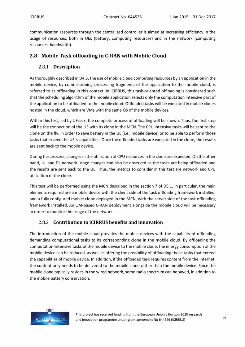
In iCIRRUS, this use case, led by Wellness Telecom (WT), is aimed at showing how the transfer of exigent computation tasks from UEs to the cloud is a feasible, sustainable approach. Thus, attention will be focused on a videoconference service, due to the significant load of computational tasks traditionally performed in the users´ devices.
WT´s UC videoconference is aimed at reducing consumption of bandwidth, and saving battery in the user equipment, benefitting from an important reduction in local processing load. In this way, it is possible to take advantage of processing resources in the Mobile Cloud Network when they are available, according to intelligent resource allocation, while we reduce the consumption of resources in the portable device, as one of the objectives of iCIRRUS.
Thus, this service will be deployed and tested, and resource consumption will be monitored, in order to analyse the benefits of iCIRRUS approach.
Regarding the testbed as described in D5.1, the scenario designed for this test is depicted in Figure 16.
Figure 16: Videoconference scenario in UC with n participants
iCIRRUS Contract No. 644526 1 Jan 2015 – 31 Dec 2017
I
This project has received funding from the European Union’s Horizon 2020 research and innovation programme under grant agreement No 644526 (iCIRRUS) 31
A set of Softphone-enabled smartphones will be used to start and participate in a video conference through UC. Apart from a functional test to demonstrate the availability of the service, a complete log will be obtained, as well as resource consumption parameters, such as CPU and RAM memory, so that it will be possible to evaluate the cloud processing load.
A Video Mixer provides the capability to create video conference rooms and is used for shaping various streams at conferences. This type of service shows a high consumption of resources in the cloud, but the UE (at mobile device level) sees: (i) its load released, saving battery (because the use of the video mixer generates the advantage of decoding of a unique video instead of n videos, where n is the number of the users of such service); and (ii) its bandwidth requirements reduced (because with the use of the video mixer, each of the n participants will need only two input data flows (for the video data and for audio data, instead of 2n). So, the usefulness of the Video Mixer usage is apparent when n ≥ 3.
The testbed required for a VMware architecture has already been described in D5.1. Once the system is deployed and configured (SIP proxy, DB and DNS properly connected and working), the users (Softphone enabled devices, with capability to send video, and implementing SIP) will be registered in the system.
In order to start a conference, a user sends the connection request to the SIP proxy by SIP. The SIP proxy consults the database to check if the user is registered. If so, the SIP proxy forwards the video call to the Video Mixer using SIP, which creates the conference room. The Video Mixer is responsible for mixing the different streams into a single stream, and distributing to each user connected to the room in question.
The Video Mixer refers the RTP flow to the RTP proxy, which maintains the RTP flows between the calling user and the users being called. The role of DNS and DHCP has been ignored for simplicity in the diagram, in order to ease the understanding of the flow of internal communications.
During an ongoing videoconference between the UEs, the resources consumed by the VMs will be monitored, using VMware, so that information about CPU and RAM memory consumption is available.
The performance of this test without the Video Mixer VM would involve a considerably higher resource consumption in the UE, as it should manage 2 streams (video and audio) for each of the n participants in the video conference room. All these streams must be processed, decoded and offered to the user in real time, which involves a high resource consumption in terms of processing/battery and bandwidth. Due to the transfer of computation to the Video Mixer VM in the cloud, every UE will only receive two streams including respectively video and audio with the whole content of the videoconference.
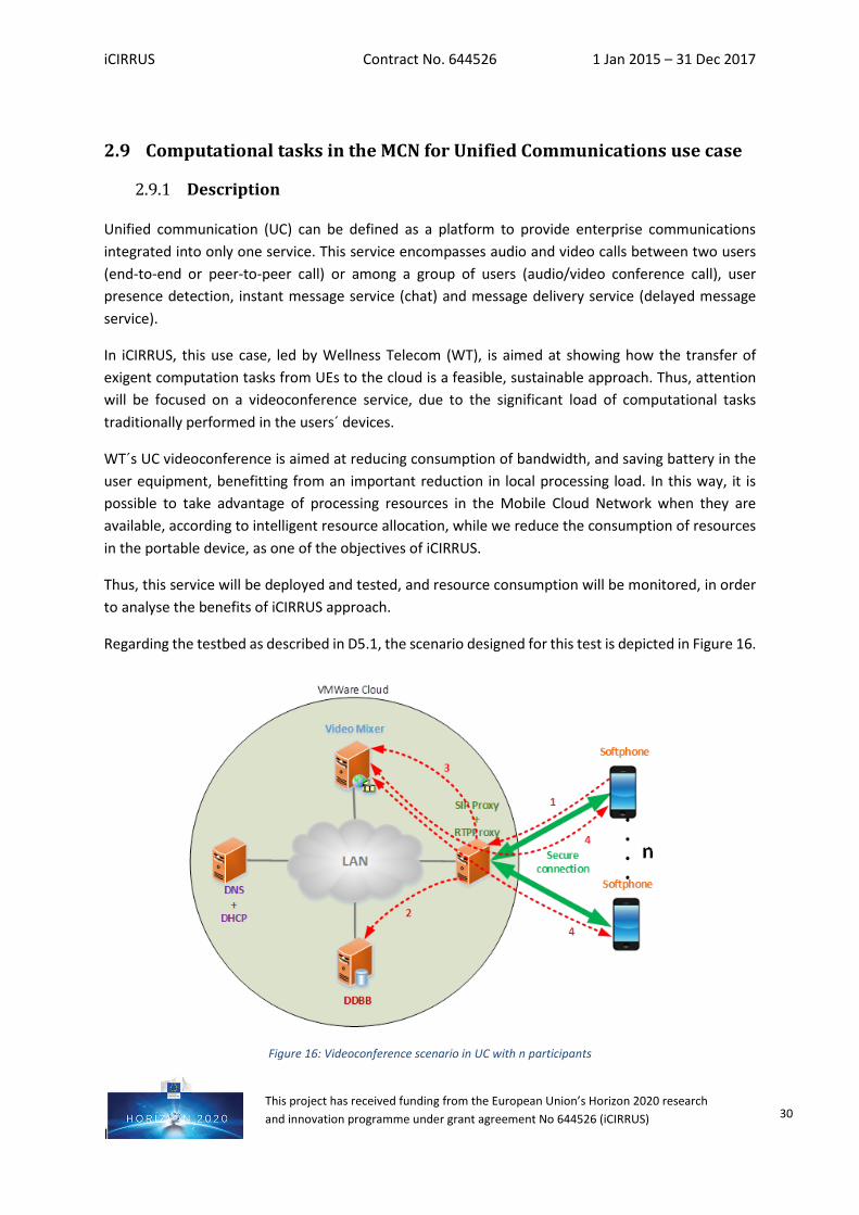
In this same show case, a VoIP and Video call peer-to-peer use case will also be demonstrated, in order to show a comparison with the videoconference service with n participants. Figure 17 describes the architecture of a peer-to-peer use case, i.e. UC with 2 participants and the communication flows.
iCIRRUS Contract No. 644526 1 Jan 2015 – 31 Dec 2017
I
This project has received funding from the European Union’s Horizon 2020 research and innovation programme under grant agreement No 644526 (iCIRRUS) 32
Figure 17: Videoconference scenario in UC with 2 participants
The first step to take place in the demonstration is the connection request sent from the UE starting the call to the SIP proxy through the SIP signalling protocol. The SIP proxy consults the database to check if the user is registered. The RTP proxy forwards RTP flows between the source and destination, supporting the media traffic between two users. In peer-to-peer calls the charge for the softphone is the same, whether processed or not by the video mixer. For the sake of simplicity, the role of the DNS and DHCP has been ignored in the diagram.
It is interesting to compare this scenario of videoconference service with two participants, in which a load reduction in the UE is achieved without using the video mixer, being comparable with simpler services such as peer-to-peer communications. In this way, both cloud network and UE resources are used sparingly.
Therefore, the benefits are greater for multi-user conference calls, as there is a lot more processing required of the mixer function which is now in the cloud. WT will provide the VoIP service for n partipants in the ICIRRUS framework. Generally speaking, it is possible to measure a complete set of metrics, in accordance with different measurement levels, such:
• at VM level: QoS metrics can be measured, in order to guarantee proper performance. In relation to resources metrics: CPU consumption, memory and storage will be monitored, as well as network metrics, such as transmitted/received bytes and packets: dropped packets and erroneous packets.
• At application level: application metrics, mainly service availability and response time will also be evaluated
Video Mixer
SIP Proxy+
RTPProxy
LAN
VMWare Cloud
Softphone
Secure connection
Softphone
DDBB
2
1
3
3DNS+
DHCP
iCIRRUS Contract No. 644526 1 Jan 2015 – 31 Dec 2017
I
This project has received funding from the European Union’s Horizon 2020 research and innovation programme under grant agreement No 644526 (iCIRRUS) 33
• At netwrork level: QoS metrics, including jitter, loss/error rate, packet delay and required bandwidth will be measured.
However, for iCIRRUS purposes, WT will focus on metrics at the VM level as well as network level and it is not necessary to measure the QoS in real-time for the validation of this service, it would be done in post-operational phase, but just after the end of the videoconference.
Contribution to iCIRRUS benefits and innovation
This test is aimed at demonstrating the feasibility of the transfer of exigent computational tasks from the UEs to the MCN, so that resource consumption, in terms of battery and bandwidth, is moved to the cloud and saved in the user´s device. Even in services involving the direct interaction of users, such as UC, it is possible to reduce the load in the devices, moving heavy processing to the cloud and taking advantage of all resources available.
2.10 D2D Communication
Description
These tests will constitute the experimental verification of some of the D2D signalling concepts studied in T4.1 D2D and D2I communications and reported in the deliverable D4.2 “iCIRRUS UE D2D & D2I interfacing”. In particular, there will be a demonstration of communication between UEs and the mobile network that will first inform the mobile network of the channel state information of the direct wireless channels between two UEs, and then send from the mobile network to the UEs the selection of the direct channel for data transmission. As the signalling protocols and LTE direct protocols that would perform these functions in a real network do not yet exist, the tests will emulate operation using in-house developed mobile applications (APPs) to exchange short message service (SMS) text messages between UEs and mobile network for D2I signalling, and Wi-Fi direct for the D2D communication data between users. A mobile APP will also request the channel measurements for different Wi-Fi channels between the UEs.
In the first sub-test, emulation will be performed through the mobile APP communicating with an SMS server in the core network. Different backhaul and core network link delays can be inserted, and the effects of such signalling delays on the effectiveness of D2D offload can be monitored. Delays will be monitored through packet inspection, ascertaining where the delays are occurring (through processing delays, network equipment etc.). Interfering Wi-Fi signals will be used to verify that correct channel choices are made. Finally, the improvement in fronthaul performance, monitored through fronthaul KPIs, will be demonstrated.
The second sub-test will be performed by extracting and inserting the messaging packets (emulating the signalling protocol) at the PDCP layer in the RAN. The reduced delay in the message exchange will be measured, and by introducing interference as in the first sub-test, improvements in the effectiveness of the offloading will be monitored. Improvement in fronthaul performance will also be monitored.

iCIRRUS Contract No. 644526 1 Jan 2015 – 31 Dec 2017
I
This project has received funding from the European Union’s Horizon 2020 research and innovation programme under grant agreement No 644526 (iCIRRUS) 34
Contribution to iCIRRUS benefits and innovation
These tests will help to demonstrate the architecture of iCIRRUS and the benefits gained by D2D communications, such as quality of data transmission, such as data rate and video quality. Also, signalling overhead will be evaluated in order to show the tradeoff between the cost (in terms of delay) and achievable benefit of data rate enhancement and offload. On completion of the second sub-test, the benefit of enabling functional splitting in the RAN can be demonstrated through the measurement results of the reduced setup delay for D2D communications.
iCIRRUS Contract No. 644526 1 Jan 2015 – 31 Dec 2017
I
This project has received funding from the European Union’s Horizon 2020 research and innovation programme under grant agreement No 644526 (iCIRRUS) 35
3 Timeline This section presents the set of the tests and the final showcase demonstrator. Once the integration tests required to obtain joint conclusions and validation towards a final demonstration in WP5 have been defined, it is necessary to plan these in order to guarantee the availability of results and conclusions according to the proper sequence of tests. Thus, interdependencies have been identified, mainly fostering a proper and successful test and validation phase (main objective of T5.3) and preventing delays that may impact on the final demonstration of iCIRRUS.
3.1 Timeline description of the tests The following descriptions of tests provide an explanation of the timeline presented in Table 3 and focus on the interdependencies.
Test 1: Real-time fronthaul platform using 60 GHz wireless: Subtest 1.1 confirms the successful migration of the DU and RU implementation to the new platform. This will be validated by measuring throughput, latency, packet loss, and jitter of the Ethernet traffic. Subtest 1.2 confirms the correct integration of a 60 GHz wireless radio link to the fronthaul system. In subtest 1.3, a client software will be connected to the UE device and a server software to the DU. This is the final test before the full integration (sub test 1.4) with the other Ethernet-based fronthaul solutions as described in section 2.5.
Test 2: CPRI over ETH transport test and verification in live LTE network: Sub test 2.1 starts the first phase after the successful FPGA board assembly. It consists of CPRI and ETH processing installation and basic operation verification. After this, CPRI to ETH and ETH to CPRI mappers/de-mappers have to be implemented. For correct conversion operation (clock recovery, latency, bit errors) and verification, a CPRI generator and measurement instrument would be used (provided by VIAVI). After successful lab verification, the module is prepared for real network equipment integration.
Sub test 2.2 starts the second phase where CPRI/ETH converters are integrated with the real network equipment (Ericsson BBU and RRU). For this purpose, 2.457 Gbps CPRI and 10Gb syncE would be used. If all works correctly, this step should not take a long time. If not, there is a time margin for error identification and correction. For this purpose, basic monitoring functions would be integrated in the FPGA firmware /software. For detailed measurement, a VIAVI CPRI measurement instrument could be used. For the initial CPRI over ETH operation, a point-to-point ETH connection would be used. The next step would be an ETH connection over a SyncE switch (Cisco ASR).
Sub test 2.3 starts the operation validation phase, after the successful integration. For this purpose BBU/RRU equipment integrated KPI registers (e.g. latency, BER) and external CPRI and ETH measurement equipment (IXIA and VIAVI) will be used. Background ETH traffic will be inserted and the optical link will be varied to stress the operation and to verify it under realistic conditions. Legacy services (voice call, data, streaming) will be tested to demonstrate the operation.
Sub test 2.4 will enable the preparation for the interconnected showcase demonstration and involves the aggregation of the 10 ETH signal (caring the CPRI signal) on the ADVA 100 GE fronthaul switch. In particular, we have to consider the time synchronisation via PtP and the overall latency of the 10G Ethernet / 100 G Ethernet aggregator.
iCIRRUS Contract No. 644526 1 Jan 2015 – 31 Dec 2017
I
This project has received funding from the European Union’s Horizon 2020 research and innovation programme under grant agreement No 644526 (iCIRRUS) 36
Test 3: Open Air Interface based Radio over Ethernet: The Open Air Interface (OAI) test (test 3) and in particular subtest 3.1 will start in April 2017 (M28) with the arrival of the FPGA boards at UniKent. By the second half of month 29, the porting of OAI software in COMExpress module in the DU will have taken place with the necessary testing to confirm proper operation. As the OAI software to be ported is already available, the aim here will be to ensure correct porting and interfacing between the DU and RU (through the FPGA board). Subtest 3.2 begins with the completion of 3.1 by porting the OAI-based split software modules into one of the COMExpress modules and performing a loopback test. The split software has already been tested in a loopback configuration, therefore the aim is again to ensure correct porting and interfacing to external components (through the FPGA board), which will include the EPC and radio head. The subtest will then proceed to expand the testbed to include both end nodes. The split software modules will be ported to both COMExpress modules (DU and RU) at which stage end-to-end tests will begin. This phase will be completed at the start of month 31, at which point Subtest 3.3 will begin and will involve the incorporation of the fronthaul intelligence unit and extraction of KPIs. It is expected that by that time all components that make up the intelligence unit server will be completed and will be residing in their corresponding VMs. All components are already in different integration (in the intelligence unit server) phases, with some already completed as standalone modules, and others under verification testing. Subtest 3.3 will be completed during the second half of month 31. These subtests conclude the ‘Open Air Interface (OAI) based Radio over Ethernet’ testbed set-up.
Test 4: Testbed integration with sync-enabled aggregator/switch. With the completion of subtests 3.2 and 3.3, subtest 4.1 will begin in the second half of month 31. By that time, the SDN algorithms will be completed and tested (the main functionality of traffic steering has already been tested with real SDN hardware). Subtest 4.2 will begin in the second half of month 33. The FPGA boards (including COMExpress modules and split software) will be brought to ADVA where integration with the TSN aggregator will take place. The subtest will be completed during the first half of month 34. For both subtests, the intelligence unit will be used to verify proper operation and demonstrate the achievements (traffic steering, load balancing, TSN operation, KPI performance improvements).
Test 5: Ethernet-based fronthaul network. Test 5 (see also Section 2.5) starts in April 2017 (M28) with the integration of the time-sensitive networking means in the FPGA. From July 2017 (M30) onwards, there are three parallel activities to integrate the individual BBU/RRH combinations from the partners IAF (CPRIoE), Kent (OAI) and HHI (60GHz) separately. In October 2017 (M34), the final integration of the three different BBU/RRH combinations is finalized. Broadly, there are dependencies on test 1 (described in Section 0) 60 GHz (HHI), test 2 (described in Section 2.2) CPRI over Ethernet (IAF/TS), and test 4 (described in Section 2.4) OAI (Kent), and on VIAVI for measurement equipment (see also Section 5.4 for details).
Test 6: virtual RAN / higher layer functional split ETH transport: This test is based in Orange’s lab using connection to their fixed backhaul network, and is not transportable to Ljubljana for the final showcase demonstration. As a result, its timeline is not dependent on other tests and it does not force such dependencies itself. The steps described in 2.6, use of a 10G TOR switch and interconnections with an EPC and MEC server, PtP overlay on a PON, and then PtMP overlay on a PON
iCIRRUS Contract No. 644526 1 Jan 2015 – 31 Dec 2017
I
This project has received funding from the European Union’s Horizon 2020 research and innovation programme under grant agreement No 644526 (iCIRRUS) 37
will be completed by month 33 (September 2017) to allow for an analysis of the validation at the end of the project.
Test 7: Video Streaming in C-RAN with Mobile Cloud. Subtest 7.1 starts in April 2017 (M28) by setting up the video streaming server/client and clone as the video proxy in the UEssex’s testbed including mobile cloud network and fronthaul, which confirms the video streaming through clone is working properly in UE. Sub-test 7.2 leading by WT will implement C2C communication and begin in June 2017 (M30). From July 2017 (M31) onwards, subtest 7.3 starts the integrated work between UEssex and WT. The video streaming server and UE’s clone will be transferred to the WT’s mobile cloud network (MCN). The CPU and network utilization monitoring of clone is fulfilled through the API of WT’s MCN, which will be completed by end of September 2017 (M33).
Test 8: Mobile Task Offloading in C-RAN with Mobile Cloud. Subtest 8.1 starts the first phase in April 2017 (M28) to develop the task offloading services (Android apps running in UE and clone respectively) using the UEssex’s testbed including mobile cloud network and fronthaul. When the first phase verifies that task offloading is working properly and sub-test 8.2 done, subtest 8.3 in the second phase will transfer the task offloading services to WT’s MCN and monitor the clone’s CPU and network utilization in WT’s MCN. Since the subtest 8.3 is technically similar to the integrated work between UEssex and WT in subtest 7.3, subtest 8.3 starts one month later than subtest 7.3 in August 2017 (M32). Subtest 8.3 will be completed by the end of September 2017 (M33).
It is worth noting than sub-test 7.2 and 8.2 are the same C2C communication integration test. It is common to test 7 and test 8 but it will be done only once and it is planned to do its implementation as a preparation phase of the final demonstrator: “mobile cloud phase in the timeline” and has to be prior to the sub-test 7.3 and sub-test 8.3. Therefore WT plans to complete this integration into TS lab in July 2017 (M31) and in collaboration with TS.
Test 9: Computational tasks in MCN for UC use case (VoIP). This test is in line with the mobile cloud validation areas and its timeline is not dependent on other tests. WT plans to complete this test integration by the end of September 2017 (M33). The VoIP service will be then available and ready for the final showcase demonstrator.
Test 10: D2D communication. The implementation of the first D2D sub-test requires an operational SMS server in the core. At present, the approach for achieving this within the fronthaul testbed is to combine OAI and Amarisoft LTE networks (RAN from the former and core network from the latter), as the Amarisoft LTE emulator allows a more straightforward incorporation of the SMS server. This will be implemented by month 29, allowing subtest 10.1 to be performed, while parallel investigations of the server implementation in OAI will continue. During months 28 and 29, there will also be investigation of the PDCP socket in the OAI LTE emulator and the extraction and insertion of messages to UEs through this socket; this work is being carried out as part of the general work on the OAI Radio over Ethernet testbed (Test 3). This will lead to sub-test 10.2 being performed in month 30.
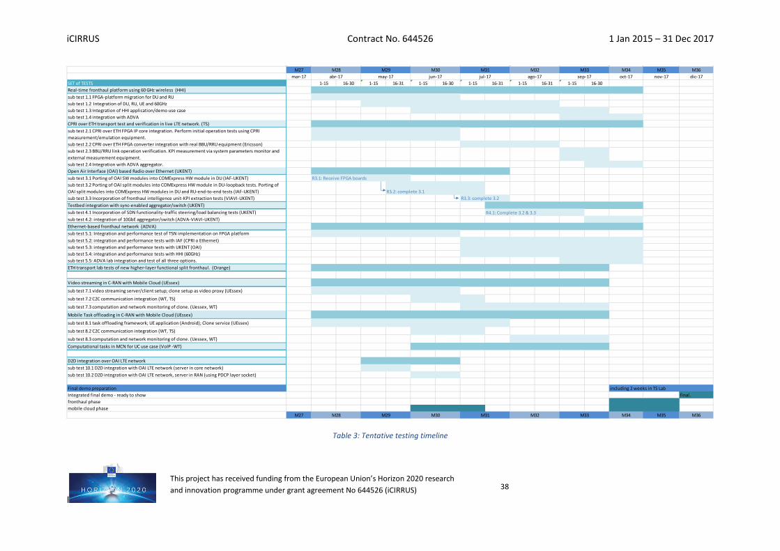
iCIRRUS Contract No. 644526 1 Jan 2015 – 31 Dec 2017
I
This project has received funding from the European Union’s Horizon 2020 research and innovation programme under grant agreement No 644526 (iCIRRUS) 38
Table 3: Tentative testing timeline
M27 M34 M35 M36mar-17 oct-17 nov-17 dic-17
SET of TESTS 1-15 16-30 1-15 16-31 1-15 16-30 1-15 16-31 1-15 16-31 1-15 16-30Real-time fronthaul platform using 60 GHz wireless (HHI)sub test 1.1 FPGA-platform migration for DU and RUsub test 1.2 Integration of DU, RU, UE and 60GHzsub test 1.3 Integration of HHI application/demo use case sub test 1.4 integration with ADVACPRI over ETH transport test and verification in live LTE network. (TS)sub test 2.1 CPRI over ETH FPGA IP core integration. Perform initial operation tests using CPRI measurement/emulation equipment.sub test 2.2 CPRI over ETH FPGA converter integration with real BBU/RRU equipment (Ericsson)sub test 2.3 BBU/RRU link operation verification. KPI measurement via system parameters monitor and external measurement equipment.sub test 2.4 Integration with ADVA aggregator.Open Air Interface (OAI) based Radio over Ethernet (UKENT)sub test 3.1 Porting of OAI SW modules into COMExpress HW module in DU (IAF-UKENT) R3.1: Receive FPGA boardssub test 3.2 Porting of OAI split modules into COMExpress HW module in DU-loopback tests. Porting of OAI split modules into COMExpress HW modules in DU and RU-end-to-end tests (IAF-UKENT) R3.2: complete 3.1 sub test 3.3 Incorporation of fronthaul intelligence unit-KPI extraction tests (VIAVI-UKENT) R3.3: complete 3.2Testbed integration with sync-enabled aggregator/switch (UKENT)sub test 4.1 Incorporation of SDN functionality-traffic steering/load balancing tests (UKENT) R4.1: Complete 3.2 & 3.3sub test 4.2: integration of 10GbE aggregator/switch (ADVA-VIAVI-UKENT)Ethernet-based fronthaul network (ADVA)sub test 5.1: Integration and performance test of TSN implementation on FPGA platformsub test 5.2: integration and performance tests with IAF (CPRI o Ethernet)sub test 5.3: integration and performance tests with UKENT (OAI)sub test 5.4: integration and performance tests with HHI (60GHz)sub test 5.5: ADVA lab integration and test of all three options. ETH transport lab tests of new higher-layer functional split fronthaul. (Orange)
Video streaming in C-RAN with Mobile Cloud (UEssex)
sub test 7.1 video streaming server/client setup; clone setup as video proxy (UEssex)
sub test 7.2 C2C communication integration (WT, TS)
sub test 7.3 computation and network monitoring of clone. (Uessex, WT)
Mobile Task offloading in C-RAN with Mobile Cloud (UEssex)
sub test 8.1 task offloading framework; UE application (Android); Clone service (UEssex)
sub test 8.2 C2C communication integration (WT, TS)
sub test 8.3 computation and network monitoring of clone. (Uessex, WT)Computational tasks in MCN for UC use case (VoIP -WT)
D2D integration over OAI LTE networksub test 10.1 D2D integration with OAI LTE network (server in core network)sub test 10.2 D2D integration with OAI LTE network, server in RAN (using PDCP layer socket)
Final demo preparation including 2 weeks in TS LabIntegrated final demo - ready to show final.fronthaul phasemobile cloud phase
M27 M34 M35 M36M33M32M31
M33jul-17 ago-17 sep-17
M30M29M28
M31 M32M28abr-17 may-17
M29 M30jun-17
iCIRRUS Contract No. 644526 1 Jan 2015 – 31 Dec 2017
I
This project has received funding from the European Union’s Horizon 2020 research and innovation programme under grant agreement No 644526 (iCIRRUS) 39
3.2 Timeline description of the final showcase demonstrator First, the consortium will proceed to carry out interconnected showcase demonstration preparation. In the last part of the integration process all presented technologies are going to be interconnected over the same fronthaul network. Preparation (final integration) is going to be partially done in parallel for fronthaul and mobile cloud part, due to technologies independence.
Mobile cloud environment preparation can start in advance (M30), because it consist of setting up of required system building block elements. The final target of this step is to prepare at TS a copy of the environment used by WT and UEssex. Due to the fact that we all use the same system visualization technology (VMware) the main operation in this preparation part is the exportation, transfer and restoration of all the system elements, which is standard procedure for virtual machines. In the last part of the demonstration preparation (M34), the final cloud configuration has to be done, in the relation with the fronthaul aggregation provided by ADVA.
In parallel the preparation for the fronthaul demonstration at TS will start in M34. At that point the ADVA fronthaul aggregator is supposed to be prepared for the OAI (Ukent) and high speed transmission (HHI) integration and tested for the CPRI over ETH transport (CPRI emulator). The major integration activities at that point are expected for the real network CPRI and system synchronization integration. For this purpose, intermediate result from stand-alone CPRI over ETH test (IAF, TS), would be useful for the frontahul aggregation preparation (ADVA, HHI, UKent, IAF).
4 Conclusions The tests and timeline presented in this document, together with the testbeds and resources described in D5.1, “Methods, material and platforms for testing of high bandwidth mobile wireless solutions”, provide a solid base for subsequent tasks focused on integration, testing and demonstration of results in a final demonstrator for iCIRRUS.
These tests have been designed in order to not only provide a progressive evaluation of integration tasks, but also to demonstrate the contribution of different modules to the global innovation and benefits provided by iCIRRUS. This approach was selected considering the heterogeneity of contributions and perspectives that coexist in this project, from communication electronics to application layer.
Hence, after individual functional tests are performed, the integration phase will take place progressively, relying on partial integration tests, as described in this document. Ten (10) tests have been defined. Regarding the validation areas, four (4) of these tests will help to validate the control plane, seven (7) the data / transport plane and three (3) the mobile cloud (some tests provide validation of more than one area).
This progressive verification of integrated performance of developments offers a secure, reliable base towards the final demonstrator. Related interconnection work and results will be published in deliverable D5.3 “Validation test setup and execution report”.

iCIRRUS Contract No. 644526 1 Jan 2015 – 31 Dec 2017
I
This project has received funding from the European Union’s Horizon 2020 research and innovation programme under grant agreement No 644526 (iCIRRUS) 40
Finally, deliverable D5.4 “Validation test results and analysis evaluation” will report the global analysis of results obtained from functional, non-functional and compliance tests within an integrated, final scenario for iCIRRUS.
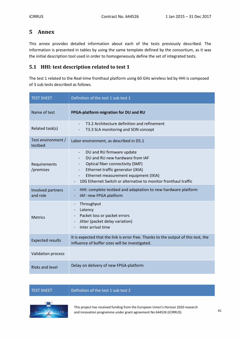
iCIRRUS Contract No. 644526 1 Jan 2015 – 31 Dec 2017
I
This project has received funding from the European Union’s Horizon 2020 research and innovation programme under grant agreement No 644526 (iCIRRUS) 41
5 Annex
This annex provides detailed information about each of the tests previously described. The information is presented in tables by using the same template defined by the consortium, as it was the initial description tool used in order to homogeneously define the set of integrated tests.
5.1 HHI: test description related to test 1
The test 1 related to the Real-time fronthaul platform using 60 GHz wireless led by HHI is composed of 3 sub tests described as follows.
TEST SHEET Definition of the test 1 sub test 1
Name of test FPGA-platform migration for DU and RU
Related task(s) - T3.2 Architecture definition and refinement - T3.3 SLA monitoring and SON concept
Test environment / testbed
Labor environment, as described in D5.1
Requirements /premises
- DU and RU firmware update - DU and RU new hardware from IAF - Optical fiber connectivity (SMF) - Ethernet traffic generator (IXIA) - Ethernet measurement equipment (IXIA)
- 10G Ethernet Switch or alternative to monitor fronthaul traffic
Involved partners and role
- HHI: complete testbed and adaptation to new hardware platform - IAF: new FPGA platform
Metrics
- Throughput - Latency - Packet loss or packet errors - Jitter (packet delay variation) - Inter arrival time
Expected results It is expected that the link is error free. Thanks to the output of this test, the influence of buffer sizes will be investigated.
Validation process
Risks and level Delay on delivery of new FPGA-platform
TEST SHEET Definition of the test 1 sub test 2
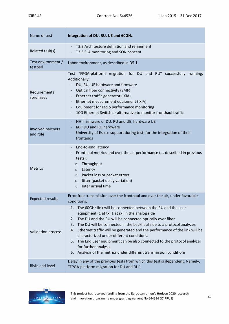
iCIRRUS Contract No. 644526 1 Jan 2015 – 31 Dec 2017
I
This project has received funding from the European Union’s Horizon 2020 research and innovation programme under grant agreement No 644526 (iCIRRUS) 42
Name of test Integration of DU, RU, UE and 60GHz
Related task(s) - T3.2 Architecture definition and refinement - T3.3 SLA monitoring and SON concept
Test environment / testbed
Labor environment, as described in D5.1
Requirements /premises
Test “FPGA-platform migration for DU and RU” successfully running. Additionally:
- DU, RU, UE hardware and firmware - Optical fiber connectivity (SMF) - Ethernet traffic generator (IXIA) - Ethernet measurement equipment (IXIA) - Equipment for radio performance monitoring - 10G Ethernet Switch or alternative to monitor fronthaul traffic
Involved partners and role
- HHI: firmware of DU, RU and UE, hardware UE - IAF: DU and RU hardware - University of Essex: support during test, for the integration of their
frontends
Metrics
- End-to-end latency - Fronthaul metrics and over the air performance (as described in previous
tests): o Throughput o Latency o Packet loss or packet errors o Jitter (packet delay variation) o Inter arrival time
Expected results Error free transmission over the fronthaul and over the air, under favorable conditions.
Validation process
1. The 60GHz link will be connected between the RU and the user equipment (1 at tx, 1 at rx) in the analog side
2. The DU and the RU will be connected optically over fiber. 3. The DU will be connected in the backhaul side to a protocol analyzer. 4. Ethernet traffic will be generated and the performance of the link will be
characterized under different conditions. 5. The End user equipment can be also connected to the protocol analyzer
for further analysis. 6. Analysis of the metrics under different transmission conditions
Risks and level Delay in any of the previous tests from which this test is dependent. Namely, “FPGA-platform migration for DU and RU”.
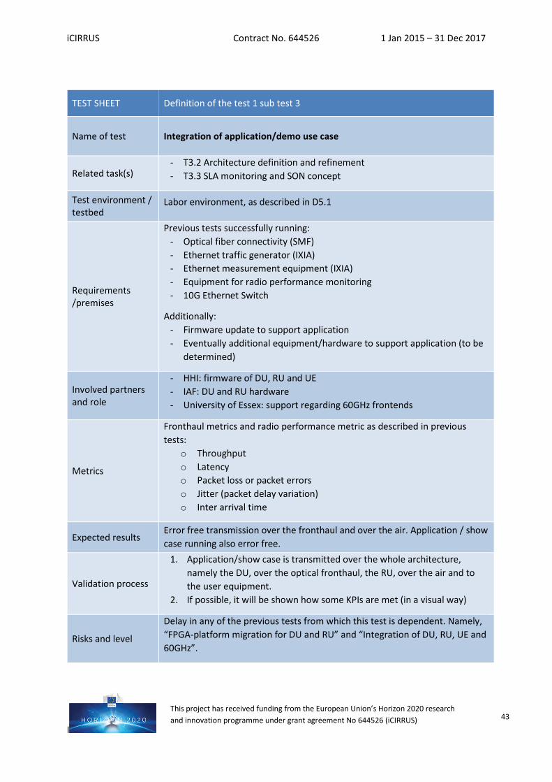
iCIRRUS Contract No. 644526 1 Jan 2015 – 31 Dec 2017
I
This project has received funding from the European Union’s Horizon 2020 research and innovation programme under grant agreement No 644526 (iCIRRUS) 43
TEST SHEET Definition of the test 1 sub test 3
Name of test Integration of application/demo use case
Related task(s) - T3.2 Architecture definition and refinement - T3.3 SLA monitoring and SON concept
Test environment / testbed
Labor environment, as described in D5.1
Requirements /premises
Previous tests successfully running: - Optical fiber connectivity (SMF) - Ethernet traffic generator (IXIA) - Ethernet measurement equipment (IXIA) - Equipment for radio performance monitoring - 10G Ethernet Switch
Additionally: - Firmware update to support application - Eventually additional equipment/hardware to support application (to be
determined)
Involved partners and role
- HHI: firmware of DU, RU and UE - IAF: DU and RU hardware - University of Essex: support regarding 60GHz frontends
Metrics
Fronthaul metrics and radio performance metric as described in previous tests:
o Throughput o Latency o Packet loss or packet errors o Jitter (packet delay variation) o Inter arrival time
Expected results Error free transmission over the fronthaul and over the air. Application / show case running also error free.
Validation process
1. Application/show case is transmitted over the whole architecture, namely the DU, over the optical fronthaul, the RU, over the air and to the user equipment.
2. If possible, it will be shown how some KPIs are met (in a visual way)
Risks and level
Delay in any of the previous tests from which this test is dependent. Namely, “FPGA-platform migration for DU and RU” and “Integration of DU, RU, UE and 60GHz”.
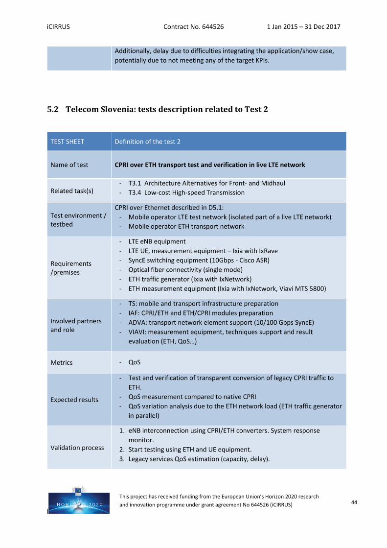
iCIRRUS Contract No. 644526 1 Jan 2015 – 31 Dec 2017
I
This project has received funding from the European Union’s Horizon 2020 research and innovation programme under grant agreement No 644526 (iCIRRUS) 44
5.2 Telecom Slovenia: tests description related to Test 2
Additionally, delay due to difficulties integrating the application/show case, potentially due to not meeting any of the target KPIs.
TEST SHEET Definition of the test 2
Name of test CPRI over ETH transport test and verification in live LTE network
Related task(s) - T3.1 Architecture Alternatives for Front- and Midhaul - T3.4 Low-cost High-speed Transmission
Test environment / testbed
CPRI over Ethernet described in D5.1: - Mobile operator LTE test network (isolated part of a live LTE network) - Mobile operator ETH transport network
Requirements /premises
- LTE eNB equipment - LTE UE, measurement equipment – Ixia with IxRave - SyncE switching equipment (10Gbps - Cisco ASR) - Optical fiber connectivity (single mode) - ETH traffic generator (Ixia with IxNetwork) - ETH measurement equipment (Ixia with IxNetwork, Viavi MTS 5800)
Involved partners and role
- TS: mobile and transport infrastructure preparation - IAF: CPRI/ETH and ETH/CPRI modules preparation - ADVA: transport network element support (10/100 Gbps SyncE) - VIAVI: measurement equipment, techniques support and result
evaluation (ETH, QoS…)
Metrics - QoS
Expected results
- Test and verification of transparent conversion of legacy CPRI traffic to ETH.
- QoS measurement compared to native CPRI - QoS variation analysis due to the ETH network load (ETH traffic generator
in parallel)
Validation process
1. eNB interconnection using CPRI/ETH converters. System response monitor.
2. Start testing using ETH and UE equipment. 3. Legacy services QoS estimation (capacity, delay).
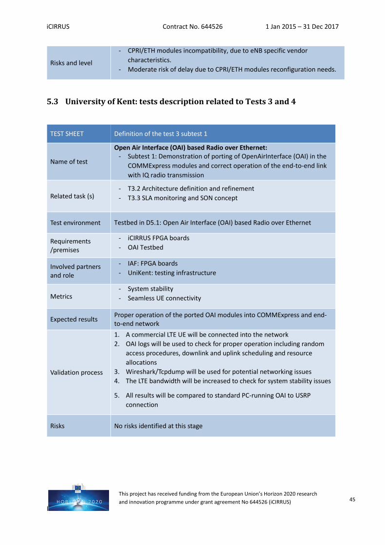
iCIRRUS Contract No. 644526 1 Jan 2015 – 31 Dec 2017
I
This project has received funding from the European Union’s Horizon 2020 research and innovation programme under grant agreement No 644526 (iCIRRUS) 45
5.3 University of Kent: tests description related to Tests 3 and 4
Risks and level
- CPRI/ETH modules incompatibility, due to eNB specific vendor characteristics.
- Moderate risk of delay due to CPRI/ETH modules reconfiguration needs.
TEST SHEET Definition of the test 3 subtest 1
Name of test
Open Air Interface (OAI) based Radio over Ethernet: - Subtest 1: Demonstration of porting of OpenAirInterface (OAI) in the
COMMExpress modules and correct operation of the end-to-end link with IQ radio transmission
Related task (s) - T3.2 Architecture definition and refinement - T3.3 SLA monitoring and SON concept
Test environment Testbed in D5.1: Open Air Interface (OAI) based Radio over Ethernet
Requirements /premises
- iCIRRUS FPGA boards - OAI Testbed
Involved partners and role
- IAF: FPGA boards - UniKent: testing infrastructure
Metrics - System stability - Seamless UE connectivity
Expected results Proper operation of the ported OAI modules into COMMExpress and end-to-end network
Validation process
1. A commercial LTE UE will be connected into the network 2. OAI logs will be used to check for proper operation including random
access procedures, downlink and uplink scheduling and resource allocations
3. Wireshark/Tcpdump will be used for potential networking issues 4. The LTE bandwidth will be increased to check for system stability issues
5. All results will be compared to standard PC-running OAI to USRP connection
Risks No risks identified at this stage
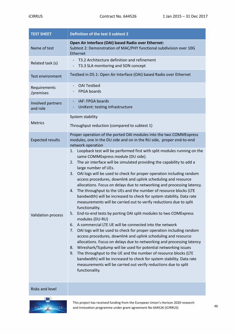
iCIRRUS Contract No. 644526 1 Jan 2015 – 31 Dec 2017
I
This project has received funding from the European Union’s Horizon 2020 research and innovation programme under grant agreement No 644526 (iCIRRUS) 46
TEST SHEET Definition of the test 3 subtest 2
Name of test Open Air Interface (OAI) based Radio over Ethernet: Subtest 2: Demonstration of MAC/PHY functional subdivision over 10G Ethernet
Related task (s) - T3.2 Architecture definition and refinement - T3.3 SLA monitoring and SON concept
Test environment Testbed in D5.1: Open Air Interface (OAI) based Radio over Ethernet
Requirements /premises
- OAI Testbed - FPGA boards
Involved partners and role
- IAF: FPGA boards - UniKent: testing infrastructure
Metrics System stability
Throughput reduction (compared to subtest 1)
Expected results Proper operation of the ported OAI modules into the two COMMExpress modules, one in the DU side and on in the RU side, proper end-to-end network operation
Validation process
1. Loopback test will be performed first with split modules running on the same COMMExpress module (DU side).
2. The air interface will be simulated providing the capability to add a large number of UEs.
3. OAI logs will be used to check for proper operation including random access procedures, downlink and uplink scheduling and resource allocations. Focus on delays due to networking and processing latency.
4. The throughput to the UEs and the number of resource blocks (LTE bandwidth) will be increased to check for system stability. Data rate measurements will be carried out to verify reductions due to split functionality.
5. End-to-end tests by porting OAI split modules to two COMExpress modules (DU-RU)
6. A commercial LTE UE will be connected into the network 7. OAI logs will be used to check for proper operation including random
access procedures, downlink and uplink scheduling and resource allocations. Focus on delays due to networking and processing latency
8. Wireshark/Tcpdump will be used for potential networking issues 9. The throughput to the UE and the number of resource blocks (LTE
bandwidth) will be increased to check for system stability. Data rate measurements will be carried out verify reductions due to split functionality.
Risks and level
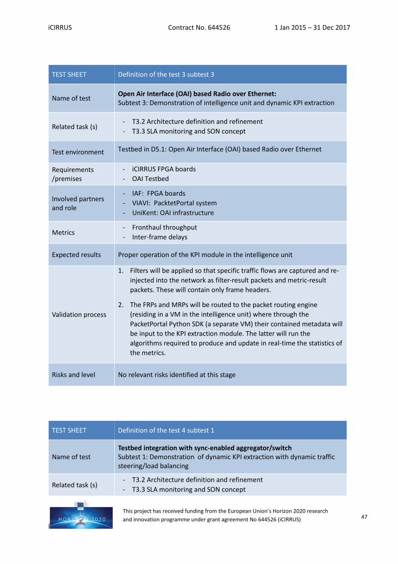
iCIRRUS Contract No. 644526 1 Jan 2015 – 31 Dec 2017
I
This project has received funding from the European Union’s Horizon 2020 research and innovation programme under grant agreement No 644526 (iCIRRUS) 47
TEST SHEET Definition of the test 4 subtest 1
Name of test Testbed integration with sync-enabled aggregator/switch Subtest 1: Demonstration of dynamic KPI extraction with dynamic traffic steering/load balancing
Related task (s) - T3.2 Architecture definition and refinement - T3.3 SLA monitoring and SON concept
TEST SHEET Definition of the test 3 subtest 3
Name of test Open Air Interface (OAI) based Radio over Ethernet: Subtest 3: Demonstration of intelligence unit and dynamic KPI extraction
Related task (s) - T3.2 Architecture definition and refinement - T3.3 SLA monitoring and SON concept
Test environment Testbed in D5.1: Open Air Interface (OAI) based Radio over Ethernet
Requirements /premises
- iCIRRUS FPGA boards - OAI Testbed
Involved partners and role
- IAF: FPGA boards - VIAVI: PacktetPortal system - UniKent: OAI infrastructure
Metrics - Fronthaul throughput - Inter-frame delays
Expected results Proper operation of the KPI module in the intelligence unit
Validation process
1. Filters will be applied so that specific traffic flows are captured and re-injected into the network as filter-result packets and metric-result packets. These will contain only frame headers.
2. The FRPs and MRPs will be routed to the packet routing engine (residing in a VM in the intelligence unit) where through the PacketPortal Python SDK (a separate VM) their contained metadata will be input to the KPI extraction module. The latter will run the algorithms required to produce and update in real-time the statistics of the metrics.
Risks and level No relevant risks identified at this stage
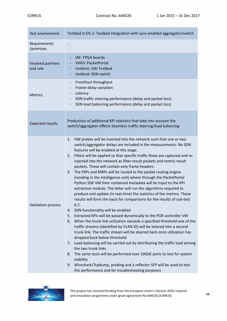
iCIRRUS Contract No. 644526 1 Jan 2015 – 31 Dec 2017
I
This project has received funding from the European Union’s Horizon 2020 research and innovation programme under grant agreement No 644526 (iCIRRUS) 48
Test environment Testbed in D5.1: Testbed integration with sync-enabled aggregator/switch
Requirements /premises
-
Involved partners and role
- IAF: FPGA boards - VIAVI: PacketPortal - UniKent: OAI Testbed - UniKent: SDN switch
Metrics
- Fronthaul throughput - Frame-delay variation - Latency - SDN traffic steering performance (delay and packet loss) - SDN load balancing performance (delay and packet loss)
Expected results Production of additional KPI statistics that take into account the switch/aggregator effects Seamless traffic steering/load balancing
Validation process
1. HW probes will be inserted into the network such that one or two switch/aggregator delays are included in the measurements. No SDN features will be enabled at this stage.
2. Filters will be applied so that specific traffic flows are captured and re-injected into the network as filter-result packets and metric-result packets. These will contain only frame headers.
3. The FRPs and MRPs will be routed to the packet routing engine (residing in the intelligence unit) where through the PacketPortal Python SDK VM their contained metadata will be input to the KPI extraction module. The latter will run the algorithms required to produce and update (in real-time) the statistics of the metrics. These results will form the basis for comparisons for the results of sub-test 6.2.
4. SDN functionality will be enabled 5. Extracted KPIs will be passed dynamically to the POX controller VM 6. When the trunk link utilization exceeds a specified threshold one of the
traffic streams (identified by VLAN ID) will be steered into a second trunk link. The traffic stream will be steered back once utilization has dropped back below threshold.
7. Load balancing will be carried out by distributing the traffic load among the two trunk links
8. The same tests will be performed over 10GbE ports to test for system stability
9. Wireshark/Tcpdump, probing and a reflector SFP will be used to test the performance and for troubleshooting purposes
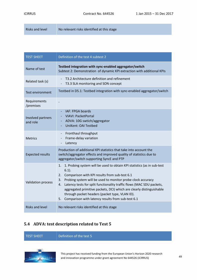
iCIRRUS Contract No. 644526 1 Jan 2015 – 31 Dec 2017
I
This project has received funding from the European Union’s Horizon 2020 research and innovation programme under grant agreement No 644526 (iCIRRUS) 49
Risks and level No relevant risks identified at this stage
TEST SHEET Definition of the test 4 subtest 2
Name of test Testbed integration with sync-enabled aggregator/switch Subtest 2: Demonstration of dynamic KPI extraction with additional KPIs
Related task (s) - T3.2 Architecture definition and refinement - T3.3 SLA monitoring and SON concept
Test environment Testbed in D5.1: Testbed integration with sync-enabled aggregator/switch
Requirements /premises
-
Involved partners and role
- IAF: FPGA boards - VIAVI: PacketPortal - ADVA: 10G swtich/aggregator - UniKent: OAI Testbed
Metrics - Fronthaul throughput - Frame-delay variation - Latency
Expected results Production of additional KPI statistics that take into account the switch/aggregator effects and improved quality of statistics due to aggregator/switch supporting SyncE and PTP
Validation process
1. 1. Probing system will be used to obtain KPI statistics (as in sub-test 6.1).
2. Comparison with KPI results from sub-test 6.1 3. Probing system will be used to monitor probe clock accuracy 4. Latency tests for split functionality traffic flows (MAC SDU packets,
aggregated primitive packets, DCI) which are clearly distinguishable through packet headers (packet type, VLAN ID).
5. Comparison with latency results from sub-test 6.1
Risks and level No relevant risks identified at this stage
5.4 ADVA: test description related to Test 5
TEST SHEET Definition of the test 5
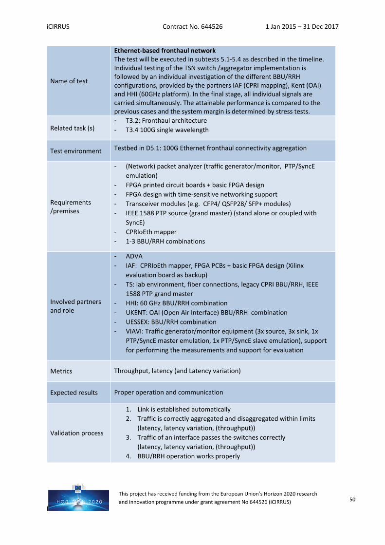
iCIRRUS Contract No. 644526 1 Jan 2015 – 31 Dec 2017
I
This project has received funding from the European Union’s Horizon 2020 research and innovation programme under grant agreement No 644526 (iCIRRUS) 50
Name of test
Ethernet-based fronthaul network The test will be executed in subtests 5.1-5.4 as described in the timeline. Individual testing of the TSN switch /aggregator implementation is followed by an individual investigation of the different BBU/RRH configurations, provided by the partners IAF (CPRI mapping), Kent (OAI) and HHI (60GHz platform). In the final stage, all individual signals are carried simultaneously. The attainable performance is compared to the previous cases and the system margin is determined by stress tests.
Related task (s) - T3.2: Fronthaul architecture - T3.4 100G single wavelength
Test environment Testbed in D5.1: 100G Ethernet fronthaul connectivity aggregation
Requirements /premises
- (Network) packet analyzer (traffic generator/monitor, PTP/SyncE emulation)
- FPGA printed circuit boards + basic FPGA design - FPGA design with time-sensitive networking support - Transceiver modules (e.g. CFP4/ QSFP28/ SFP+ modules) - IEEE 1588 PTP source (grand master) (stand alone or coupled with
SyncE) - CPRIoEth mapper - 1-3 BBU/RRH combinations
Involved partners and role
- ADVA - IAF: CPRIoEth mapper, FPGA PCBs + basic FPGA design (Xilinx
evaluation board as backup) - TS: lab environment, fiber connections, legacy CPRI BBU/RRH, IEEE
1588 PTP grand master - HHI: 60 GHz BBU/RRH combination - UKENT: OAI (Open Air Interface) BBU/RRH combination - UESSEX: BBU/RRH combination - VIAVI: Traffic generator/monitor equipment (3x source, 3x sink, 1x
PTP/SyncE master emulation, 1x PTP/SyncE slave emulation), support for performing the measurements and support for evaluation
Metrics Throughput, latency (and Latency variation)
Expected results Proper operation and communication
Validation process
1. Link is established automatically 2. Traffic is correctly aggregated and disaggregated within limits
(latency, latency variation, (throughput)) 3. Traffic of an interface passes the switches correctly
(latency, latency variation, (throughput)) 4. BBU/RRH operation works properly
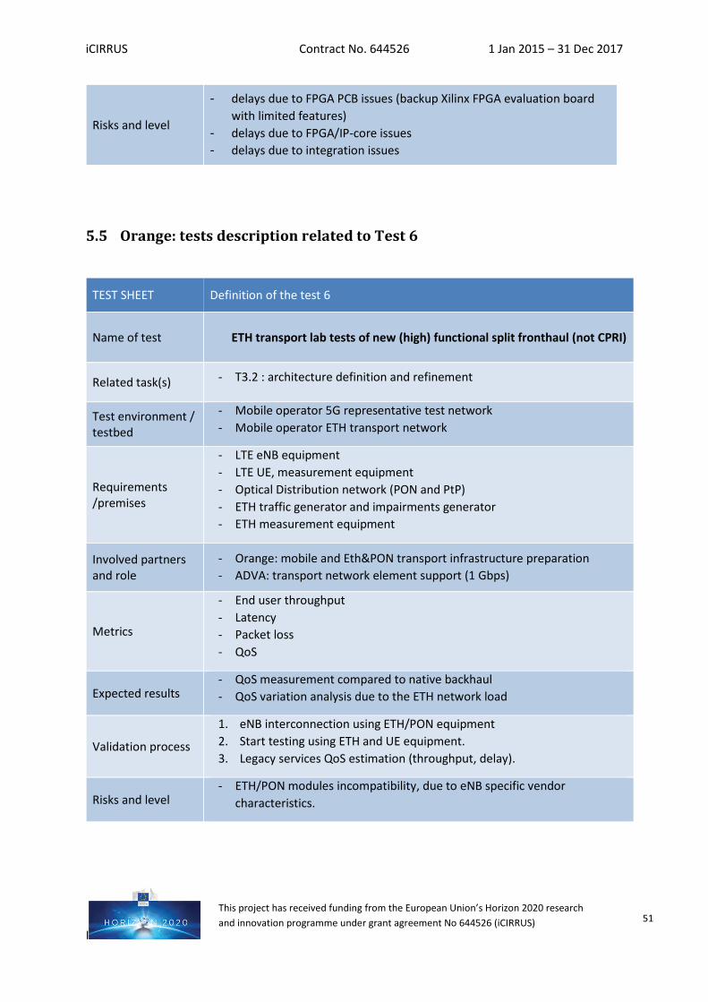
iCIRRUS Contract No. 644526 1 Jan 2015 – 31 Dec 2017
I
This project has received funding from the European Union’s Horizon 2020 research and innovation programme under grant agreement No 644526 (iCIRRUS) 51
5.5 Orange: tests description related to Test 6
Risks and level
- delays due to FPGA PCB issues (backup Xilinx FPGA evaluation board with limited features)
- delays due to FPGA/IP-core issues - delays due to integration issues
TEST SHEET Definition of the test 6
Name of test ETH transport lab tests of new (high) functional split fronthaul (not CPRI)
Related task(s) - T3.2 : architecture definition and refinement
Test environment / testbed
- Mobile operator 5G representative test network - Mobile operator ETH transport network
Requirements /premises
- LTE eNB equipment - LTE UE, measurement equipment - Optical Distribution network (PON and PtP) - ETH traffic generator and impairments generator - ETH measurement equipment
Involved partners and role
- Orange: mobile and Eth&PON transport infrastructure preparation - ADVA: transport network element support (1 Gbps)
Metrics
- End user throughput - Latency - Packet loss - QoS
Expected results - QoS measurement compared to native backhaul - QoS variation analysis due to the ETH network load
Validation process
1. eNB interconnection using ETH/PON equipment 2. Start testing using ETH and UE equipment. 3. Legacy services QoS estimation (throughput, delay).
Risks and level - ETH/PON modules incompatibility, due to eNB specific vendor
characteristics.
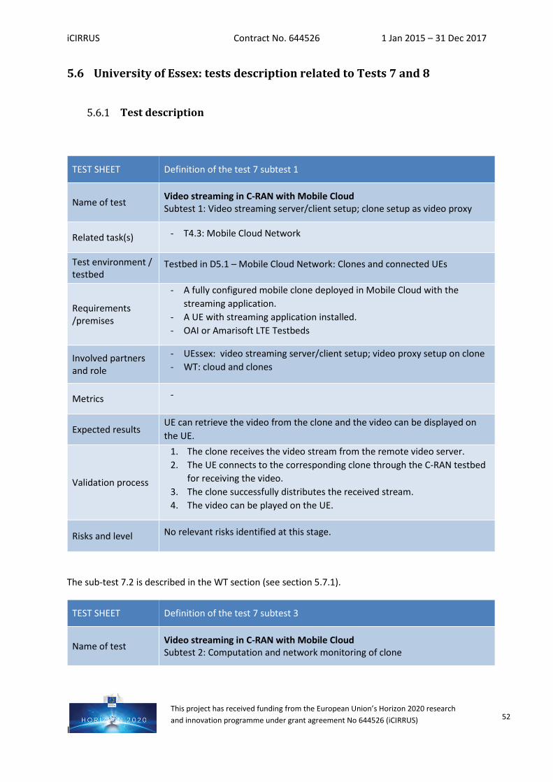
iCIRRUS Contract No. 644526 1 Jan 2015 – 31 Dec 2017
I
This project has received funding from the European Union’s Horizon 2020 research and innovation programme under grant agreement No 644526 (iCIRRUS) 52
5.6 University of Essex: tests description related to Tests 7 and 8
Test description
The sub-test 7.2 is described in the WT section (see section 5.7.1).
TEST SHEET Definition of the test 7 subtest 1
Name of test Video streaming in C-RAN with Mobile Cloud Subtest 1: Video streaming server/client setup; clone setup as video proxy
Related task(s) - T4.3: Mobile Cloud Network
Test environment / testbed
Testbed in D5.1 – Mobile Cloud Network: Clones and connected UEs
Requirements /premises
- A fully configured mobile clone deployed in Mobile Cloud with the streaming application.
- A UE with streaming application installed. - OAI or Amarisoft LTE Testbeds
Involved partners and role
- UEssex: video streaming server/client setup; video proxy setup on clone - WT: cloud and clones
Metrics -
Expected results UE can retrieve the video from the clone and the video can be displayed on the UE.
Validation process
1. The clone receives the video stream from the remote video server. 2. The UE connects to the corresponding clone through the C-RAN testbed
for receiving the video. 3. The clone successfully distributes the received stream. 4. The video can be played on the UE.
Risks and level No relevant risks identified at this stage.
TEST SHEET Definition of the test 7 subtest 3
Name of test Video streaming in C-RAN with Mobile Cloud Subtest 2: Computation and network monitoring of clone
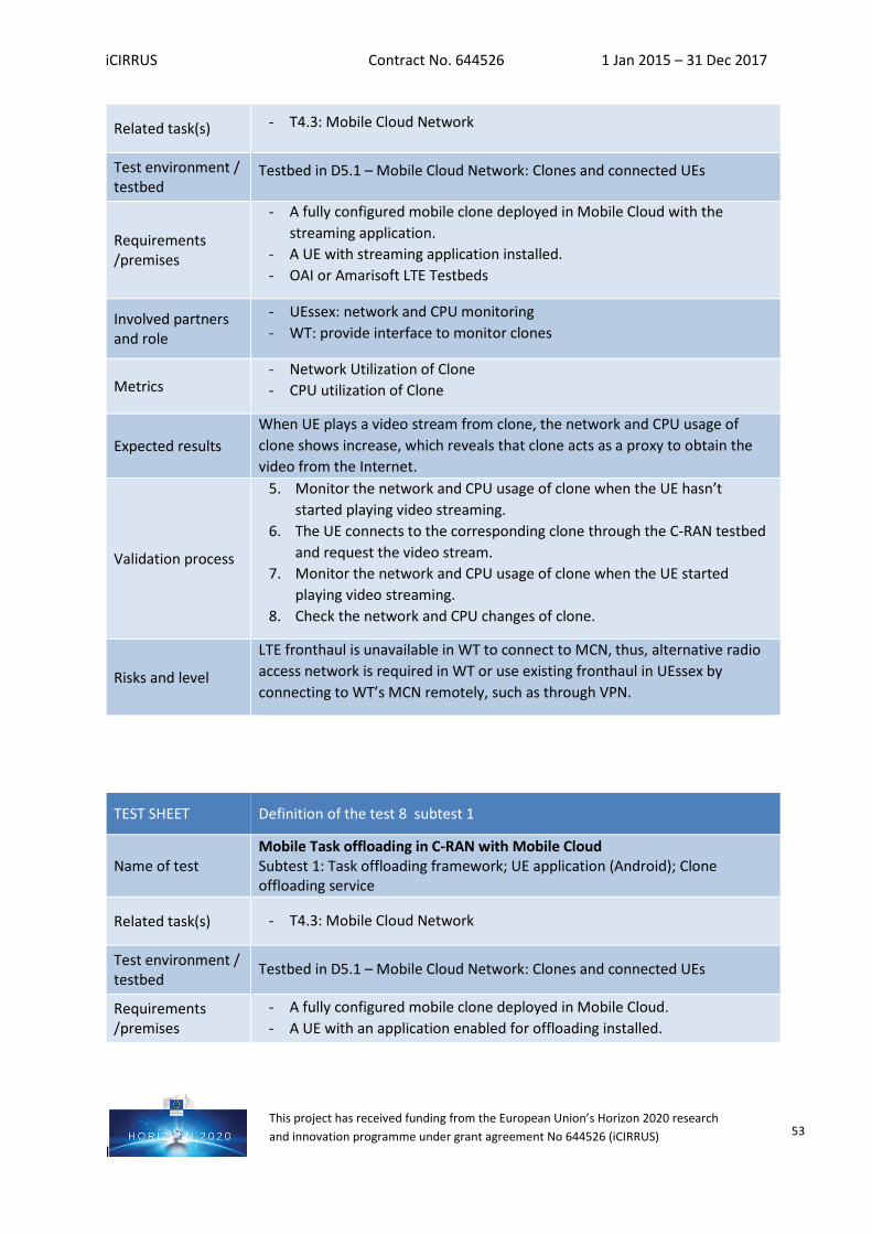
iCIRRUS Contract No. 644526 1 Jan 2015 – 31 Dec 2017
I
This project has received funding from the European Union’s Horizon 2020 research and innovation programme under grant agreement No 644526 (iCIRRUS) 53
Related task(s) - T4.3: Mobile Cloud Network
Test environment / testbed
Testbed in D5.1 – Mobile Cloud Network: Clones and connected UEs
Requirements /premises
- A fully configured mobile clone deployed in Mobile Cloud with the streaming application.
- A UE with streaming application installed. - OAI or Amarisoft LTE Testbeds
Involved partners and role
- UEssex: network and CPU monitoring - WT: provide interface to monitor clones
Metrics - Network Utilization of Clone - CPU utilization of Clone
Expected results When UE plays a video stream from clone, the network and CPU usage of clone shows increase, which reveals that clone acts as a proxy to obtain the video from the Internet.
Validation process
5. Monitor the network and CPU usage of clone when the UE hasn’t started playing video streaming.
6. The UE connects to the corresponding clone through the C-RAN testbed and request the video stream.
7. Monitor the network and CPU usage of clone when the UE started playing video streaming.
8. Check the network and CPU changes of clone.
Risks and level
LTE fronthaul is unavailable in WT to connect to MCN, thus, alternative radio access network is required in WT or use existing fronthaul in UEssex by connecting to WT’s MCN remotely, such as through VPN.
TEST SHEET Definition of the test 8 subtest 1
Name of test Mobile Task offloading in C-RAN with Mobile Cloud Subtest 1: Task offloading framework; UE application (Android); Clone offloading service
Related task(s) - T4.3: Mobile Cloud Network
Test environment / testbed
Testbed in D5.1 – Mobile Cloud Network: Clones and connected UEs
Requirements /premises
- A fully configured mobile clone deployed in Mobile Cloud. - A UE with an application enabled for offloading installed.
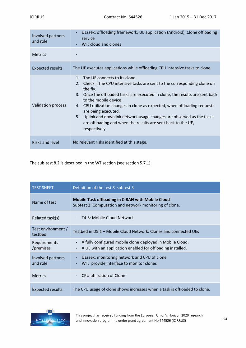
iCIRRUS Contract No. 644526 1 Jan 2015 – 31 Dec 2017
I
This project has received funding from the European Union’s Horizon 2020 research and innovation programme under grant agreement No 644526 (iCIRRUS) 54
The sub-test 8.2 is described in the WT section (see section 5.7.1).
Involved partners and role
- UEssex: offloading framework, UE application (Android), Clone offloading service
- WT: cloud and clones
Metrics -
Expected results The UE executes applications while offloading CPU intensive tasks to clone.
Validation process
1. The UE connects to its clone. 2. Check if the CPU intensive tasks are sent to the corresponding clone on
the fly. 3. Once the offloaded tasks are executed in clone, the results are sent back
to the mobile device. 4. CPU utilization changes in clone as expected, when offloading requests
are being executed. 5. Uplink and downlink network usage changes are observed as the tasks
are offloading and when the results are sent back to the UE, respectively.
Risks and level No relevant risks identified at this stage.
TEST SHEET Definition of the test 8 subtest 3
Name of test Mobile Task offloading in C-RAN with Mobile Cloud Subtest 2: Computation and network monitoring of clone.
Related task(s) - T4.3: Mobile Cloud Network
Test environment / testbed
Testbed in D5.1 – Mobile Cloud Network: Clones and connected UEs
Requirements /premises
- A fully configured mobile clone deployed in Mobile Cloud. - A UE with an application enabled for offloading installed.
Involved partners and role
- UEssex: monitoring network and CPU of clone - WT: provide interface to monitor clones
Metrics - CPU utilization of Clone
Expected results The CPU usage of clone shows increases when a task is offloaded to clone.
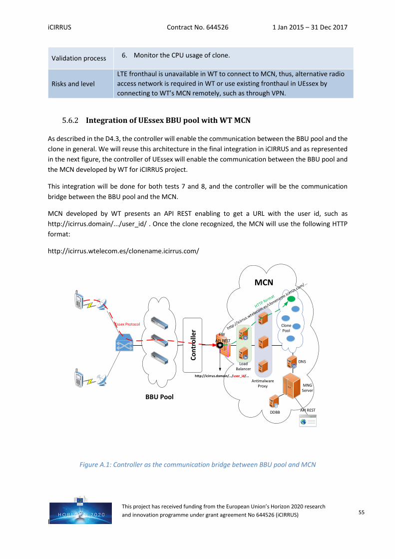
iCIRRUS Contract No. 644526 1 Jan 2015 – 31 Dec 2017
I
This project has received funding from the European Union’s Horizon 2020 research and innovation programme under grant agreement No 644526 (iCIRRUS) 55
Integration of UEssex BBU pool with WT MCN
As described in the D4.3, the controller will enable the communication between the BBU pool and the clone in general. We will reuse this architecture in the final integration in iCIRRUS and as represented in the next figure, the controller of UEssex will enable the communication between the BBU pool and the MCN developed by WT for iCIRRUS project.
This integration will be done for both tests 7 and 8, and the controller will be the communication bridge between the BBU pool and the MCN.
MCN developed by WT presents an API REST enabling to get a URL with the user id, such as http://icirrus.domain/.../user_id/ . Once the clone recognized, the MCN will use the following HTTP format:
http://icirrus.wtelecom.es/clonename.icirrus.com/
BBU Pool
MCN
Clone Pool
Antimalware Proxy
Load Balancer
FW
DDBB
MNG Server
DNS
API REST
API REST
http://icirrus.domain/…/user_id/...
Essex Protocol
Cont
rolle
r
Figure A.1: Controller as the communication bridge between BBU pool and MCN
Validation process 6. Monitor the CPU usage of clone.
Risks and level LTE fronthaul is unavailable in WT to connect to MCN, thus, alternative radio access network is required in WT or use existing fronthaul in UEssex by connecting to WT’s MCN remotely, such as through VPN.
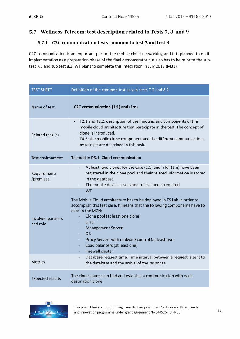
iCIRRUS Contract No. 644526 1 Jan 2015 – 31 Dec 2017
I
This project has received funding from the European Union’s Horizon 2020 research and innovation programme under grant agreement No 644526 (iCIRRUS) 56
5.7 Wellness Telecom: test description related to Tests 7, 8 and 9
C2C communication tests common to test 7and test 8
C2C communication is an important part of the mobile cloud networking and it is planned to do its implementation as a preparation phase of the final demonstrator but also has to be prior to the sub-test 7.3 and sub test 8.3. WT plans to complete this integration in July 2017 (M31).
TEST SHEET Definition of the common test as sub-tests 7.2 and 8.2
Name of test C2C communication (1:1) and (1:n)
Related task (s)
- T2.1 and T2.2: description of the modules and components of the mobile cloud architecture that participate in the test. The concept of clone is introduced.
- T4.3: the mobile clone component and the different communications by using it are described in this task.
Test environment Testbed in D5.1: Cloud communication
Requirements /premises
- At least, two clones for the case (1:1) and n for (1:n) have been registered in the clone pool and their related information is stored in the database
- The mobile device associated to its clone is required
Involved partners and role
- WT
The Mobile Cloud architecture has to be deployed in TS Lab in order to accomplish this test case. It means that the following components have to exist in the MCN:
- Clone pool (at least one clone) - DNS - Management Server - DB - Proxy Servers with malware control (at least two) - Load balancers (at least one) - Firewall cluster
Metrics - Database request time: Time interval between a request is sent to
the database and the arrival of the response
Expected results The clone source can find and establish a communication with each destination clone.
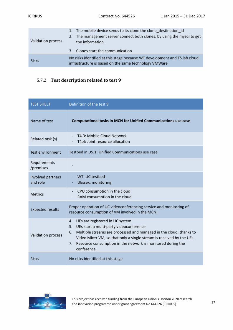
iCIRRUS Contract No. 644526 1 Jan 2015 – 31 Dec 2017
I
This project has received funding from the European Union’s Horizon 2020 research and innovation programme under grant agreement No 644526 (iCIRRUS) 57
Test description related to test 9
Validation process
1. The mobile device sends to its clone the clone_destination_id 2. The management server connect both clones, by using the mysql to get
the information.
3. Clones start the communication
Risks No risks identified at this stage because WT development and TS lab cloud infrastructure is based on the same technology VMWare
TEST SHEET Definition of the test 9
Name of test Computational tasks in MCN for Unified Communications use case
Related task (s) - T4.3: Mobile Cloud Network - T4.4: Joint resource allocation
Test environment Testbed in D5.1: Unified Communications use case
Requirements /premises
-
Involved partners and role
- WT: UC testbed - UEssex: monitoring
Metrics - CPU consumption in the cloud - RAM consumption in the cloud
Expected results Proper operation of UC videoconferencing service and monitoring of resource consumption of VM involved in the MCN.
Validation process
4. UEs are registered in UC system 5. UEs start a multi-party videoconference 6. Multiple streams are processed and managed in the cloud, thanks to
Video Mixer VM, so that only a single stream is received by the UEs. 7. Resource consumption in the network is monitored during the
conference.
Risks No risks identified at this stage
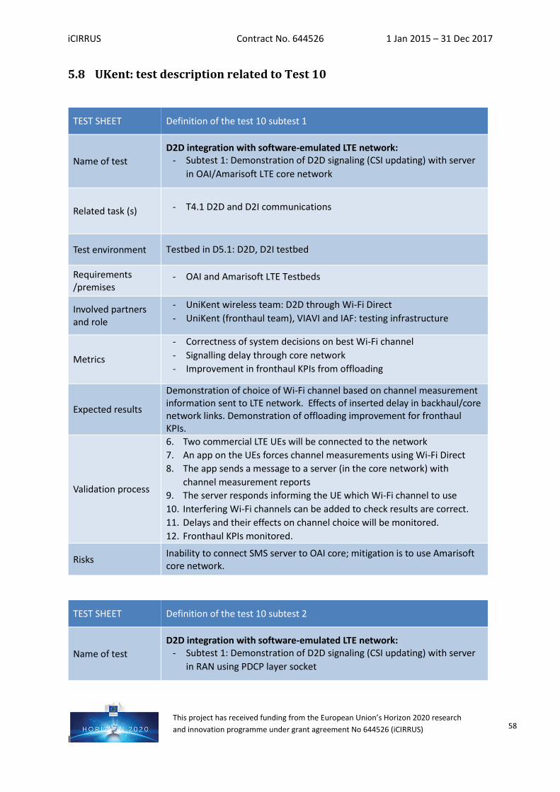
iCIRRUS Contract No. 644526 1 Jan 2015 – 31 Dec 2017
I
This project has received funding from the European Union’s Horizon 2020 research and innovation programme under grant agreement No 644526 (iCIRRUS) 58
5.8 UKent: test description related to Test 10
TEST SHEET Definition of the test 10 subtest 1
Name of test D2D integration with software-emulated LTE network:
- Subtest 1: Demonstration of D2D signaling (CSI updating) with server in OAI/Amarisoft LTE core network
Related task (s) - T4.1 D2D and D2I communications
Test environment Testbed in D5.1: D2D, D2I testbed
Requirements /premises
- OAI and Amarisoft LTE Testbeds
Involved partners and role
- UniKent wireless team: D2D through Wi-Fi Direct - UniKent (fronthaul team), VIAVI and IAF: testing infrastructure
Metrics
- Correctness of system decisions on best Wi-Fi channel - Signalling delay through core network - Improvement in fronthaul KPIs from offloading
Expected results
Demonstration of choice of Wi-Fi channel based on channel measurement information sent to LTE network. Effects of inserted delay in backhaul/core network links. Demonstration of offloading improvement for fronthaul KPIs.
Validation process
6. Two commercial LTE UEs will be connected to the network 7. An app on the UEs forces channel measurements using Wi-Fi Direct 8. The app sends a message to a server (in the core network) with
channel measurement reports 9. The server responds informing the UE which Wi-Fi channel to use 10. Interfering Wi-Fi channels can be added to check results are correct. 11. Delays and their effects on channel choice will be monitored. 12. Fronthaul KPIs monitored.
Risks Inability to connect SMS server to OAI core; mitigation is to use Amarisoft core network.
TEST SHEET Definition of the test 10 subtest 2
Name of test D2D integration with software-emulated LTE network:
- Subtest 1: Demonstration of D2D signaling (CSI updating) with server in RAN using PDCP layer socket
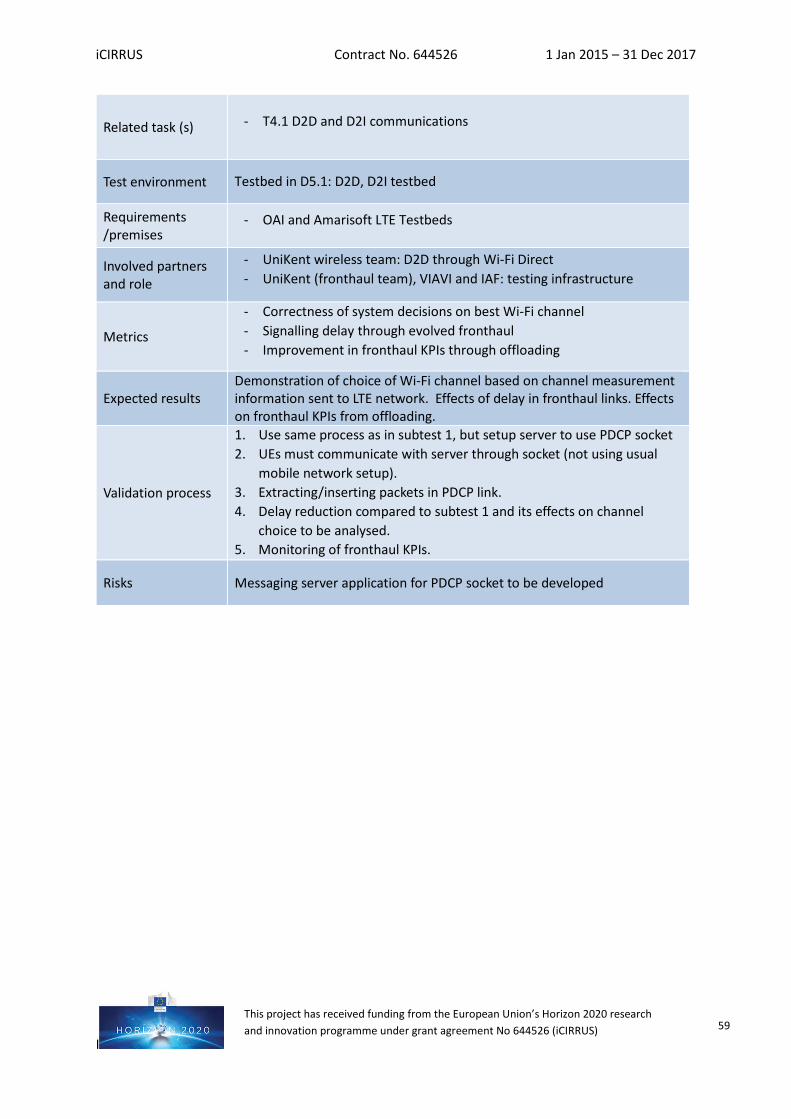
iCIRRUS Contract No. 644526 1 Jan 2015 – 31 Dec 2017
I
This project has received funding from the European Union’s Horizon 2020 research and innovation programme under grant agreement No 644526 (iCIRRUS) 59
Related task (s) - T4.1 D2D and D2I communications
Test environment Testbed in D5.1: D2D, D2I testbed
Requirements /premises
- OAI and Amarisoft LTE Testbeds
Involved partners and role
- UniKent wireless team: D2D through Wi-Fi Direct - UniKent (fronthaul team), VIAVI and IAF: testing infrastructure
Metrics
- Correctness of system decisions on best Wi-Fi channel - Signalling delay through evolved fronthaul - Improvement in fronthaul KPIs through offloading
Expected results Demonstration of choice of Wi-Fi channel based on channel measurement information sent to LTE network. Effects of delay in fronthaul links. Effects on fronthaul KPIs from offloading.
Validation process
1. Use same process as in subtest 1, but setup server to use PDCP socket 2. UEs must communicate with server through socket (not using usual
mobile network setup). 3. Extracting/inserting packets in PDCP link. 4. Delay reduction compared to subtest 1 and its effects on channel
choice to be analysed. 5. Monitoring of fronthaul KPIs.
Risks Messaging server application for PDCP socket to be developed