Embed Size (px)
Citation preview

1
FOLD
iQpump1000 is UL approved for single-phase and three-phase AC input voltage
Intelligent Pump Drive200-240V Three Phase: 3/4 to 175 HP
380-480V Three Phase: 1 to 500 HP 500-600V Three Phase: 2 to 250 HP
2
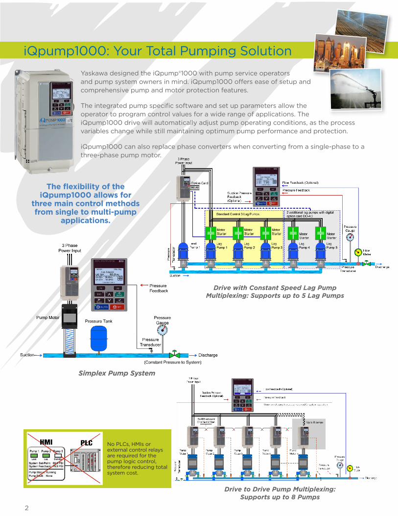
Simplex Pump System
Drive with Constant Speed Lag Pump Multiplexing: Supports up to 5 Lag Pumps
iQpump1000: Your Total Pumping Solution
Yaskawa designed the iQpump®1000 with pump service operators and pump system owners in mind. iQpump1000 offers ease of setup and comprehensive pump and motor protection features.
The integrated pump specific software and set up parameters allow the operator to program control values for a wide range of applications. The iQpump1000 drive will automatically adjust pump operating conditions, as the process variables change while still maintaining optimum pump performance and protection.
iQpump1000 can also replace phase converters when converting from a single-phase to a three-phase pump motor.
The flexibility of the iQpump1000 allows for
three main control methods from single to multi-pump
applications.
Drive to Drive Pump Multiplexing:Supports up to 8 Pumps
No PLCs, HMIs or external control relays are required for the pump logic control, therefore reducing total system cost.

3
System Benefits
iTunes App
Energy savings app for the iPhone and the iPod touch is available at iTunes.com - search for Yaskawa.
• Commercial and Residential Irrigation, Fluid Storage Tanks
• Settling Ponds, Sewage Lift Stations
• Booster Pump Stations (Municipal, High-rises, Condos, Apartment Complexes, Residential Developments)
Improved Process Control
By matching pump output flow or pressure directly to the process requirements, applications can be fine tuned more rapidly by iQpump1000 than by other control forms. Improved System Reliability
Any reduction in speed achieved by using iQpump1000 has major benefits in reducing pump wear, particularly in bearings and seals. Reduce Total System Cost
iQpump1000 lowers system cost by eliminating sensors, jockey pumps, restriction valves, as well as reducing pressure tank sizing. Energy Savings
Depending on the application, iQpump1000 reduces the demand for energy by 20 to 50% by adjusting pump speed to match a lower flow/pressure.
Ease of Installation and Set Up
iQpump1000 uses pump terminology on all setup parameters and monitors. Application presets apply most of the parameters for you. Also included is a “Pump Quick Setup” menu. Eliminate Complex Control Panels
By installing iQpump1000, many electromechanical controls can be eliminated. This reduces the maintenance that these panels require. Reduce Mechanical Stress and Damage to Pumps
iQpump1000 has soft-start and soft-stop capabilities, which eliminate pressure surges and water hammer. Cooler Running Pump Motor
Soft start eliminates inrush current, dramatically increasing winding insulation life.

4
Real Time Clock
The iQpump1000 is supported with a real time clock that will log the last 10 fault events with a date and time stamp to provide the pump service technicians with real data for troubleshooting. This feature also enables the user to set calendar run and stop configurations, allowing the system to avoid high utility KW rates during peak day time hours.
System Pressure Setpoint
Pump Motor Output Frequency
Transducer Feedback
Control Operation Status: Drive being controlled via keypad operation or by external run command.
Drive Status Monitors: By using F1 & F2 user can quickly scroll though drive running status such as motor amps, motor speed, power consumed, etc.
Designed with Pump Operators in Mind
Designed with the user in mind, iQpump1000 uses intuitive pump related terminology, with simple process control selection of engineering units such as PSI, GPM, Feet, Metric, Temperature, Inches of Mercury, and many other process control units.
Operator Keypad
What makes iQpump1000 the industry standard is the simplicity of the operator keypad messages that are formatted in pump terminology. This informs the user the status of the system operation along with alarms or specific pump algorithm functions that are being initiated.
Pump Specific HOA Operator
Date & Time Stamp
Pre-programmed applications presets reduce start-up time significantly. Users enter simple motor and application information within the pump quick setup menu for each of the application programs.
Constant Pressure
Pump Down Level Control
Geothermal Control
Vertical Turbine Pump Pressure Control(VTC)
General Purpose Mode
APPLICATION PRESETS:
Pre-Programmed Application Macros

5
Options
Enjoy a significant amount of standard control points. The iQpump1000 can also expand to support popular communication networks.
Expansion I/O Capability• Analog Output Module (AO-A3)• Digital Output Module (DO-A3)
Communication Network OptionsIndustrial Communication• Modbus RTU (built-in)• DeviceNet• EtherNet/IP• Modbus TCP/IP• PROFIBUS-DP• PROFINET
Building Automation Networks (BAS)• BACnet• Lonworks• Metasys (N2)• Apogee (P1)
Standard I/O• (8) Digital Inputs
• (3) Analog Inputs
• (1) Pulse Input
• Drive Fault Form C Relay
• (3) Programmable Digital Outputs
• (1) Form C Relay• (2) Form A Relays• (2) Programmable Analog Outputs
• RS485 Modbus RTU Communication
Comparison of Operating Points for Throttling (A) and Adjustable Speed (B) Flow Control.
Typical power requirements and savings for throttling and bypass methods to adjustable speed method.
100,000 sq. ft. building operated 4000 hrs/year. (One 50 HP booster pump). Based on Energy Savings Predictor iQpump1000 Software.
Typical Pump Energy Consumption/Savings
TOTAL HEAD (FT)
FLOW (GPM)
OPEN SYSTEM
TOTA
L H
EA
D (F
T)
100
90
80
70
60
50
40
30
20
10
0 480 720 960 1200
A3A2
A1
B3
B2
B1
INPUT POWER (HP)
FLOW (%)
25
20
15
10
5
0 40 60 80 100
THROTTLINGMETHOD
ADJUSTABLESPEEDMETHOD
POWERSAVINGS
BYPASS METHOD
INP
UT
PO
WE
R (H
P)
Bypass Throttling iQpump1000
kW(T
hous
ands
)
160140120100
80604020
0
PC SCADA Troubleshooting, Monitoring, Startup Wizard, Programming, and Trending.
Utility Harmonics EstimatorEstimation of harmonics contribution back to main power source.
Energy Savings PredictorAnalysis of energy savings with carbon footprint calculation.
Parameter Conversion Mobile App
Web app for product conversion of existing iQpump parameter settings to the new iQpump1000 with Save Function to recall modified parameters when cell service is not available. Available for IOS, Android, Windows Mobile, and Kindle Fire platforms.
6
Pump Fault and Alarms
iQpump1000 provides a comprehensive set of pump related alarms and faults. Faults are displayed on the keypad in clear text to eliminate confusion (the following is just a sample):• Over Cycling • No Flow • Loss of Prime • Transducer Feedback Lost • Over Torque • Pumping Over Cycle• Dry Well • Broken Pipe Detection • Low and High Feedback Detection
iQpump1000 Drive Protection• Over / Under Voltage • Input Phase Loss • Phase Imbalance• Short Circuit • Over Temperature • Heatsink Fan Failure
Motor Protection• Output Phase Loss • Ground Fault • Motor Overload • Motor Over Temperature • Broken Shaft • Minimum Speed
Protection
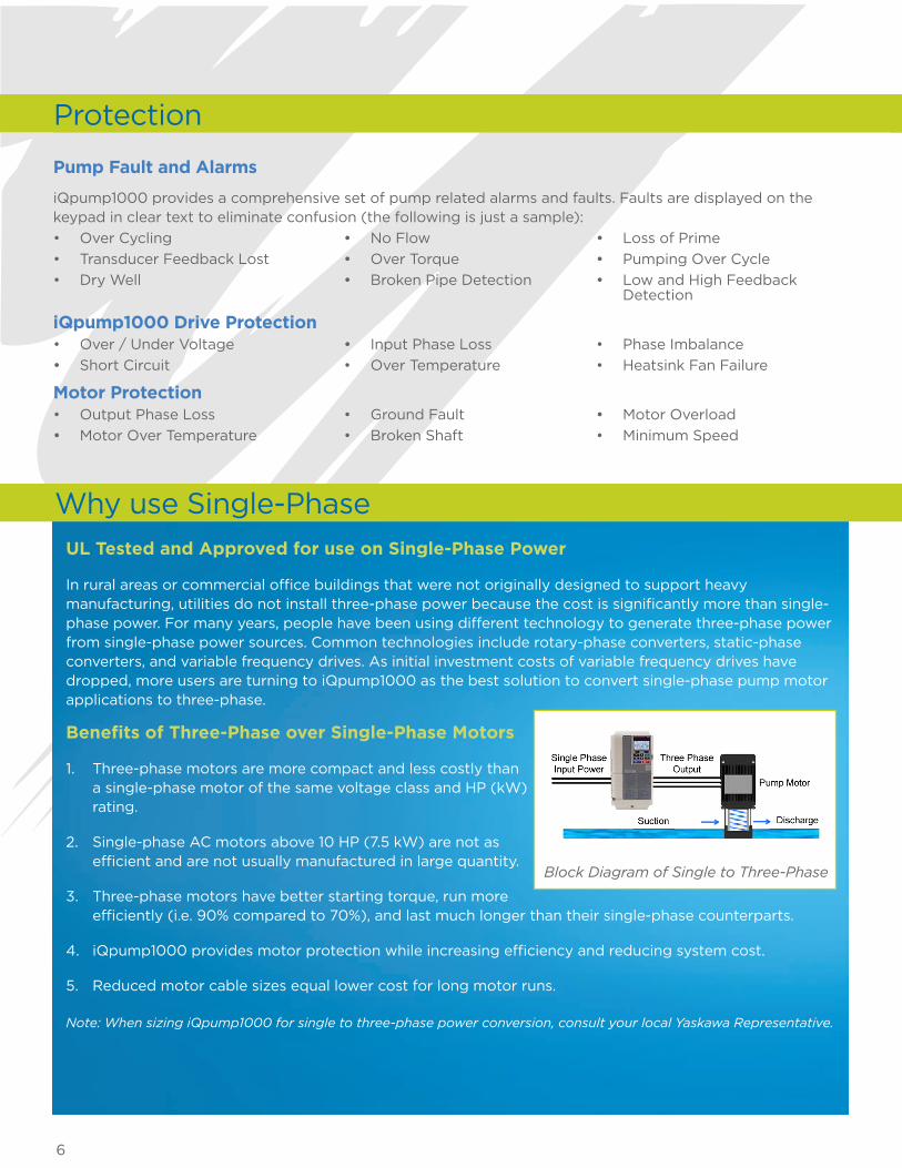
UL Tested and Approved for use on Single-Phase Power
In rural areas or commercial office buildings that were not originally designed to support heavy manufacturing, utilities do not install three-phase power because the cost is significantly more than single-phase power. For many years, people have been using different technology to generate three-phase power from single-phase power sources. Common technologies include rotary-phase converters, static-phase converters, and variable frequency drives. As initial investment costs of variable frequency drives have dropped, more users are turning to iQpump1000 as the best solution to convert single-phase pump motor applications to three-phase.
Benefits of Three-Phase over Single-Phase Motors
1. Three-phase motors are more compact and less costly than a single-phase motor of the same voltage class and HP (kW) rating.
2. Single-phase AC motors above 10 HP (7.5 kW) are not as efficient and are not usually manufactured in large quantity.
3. Three-phase motors have better starting torque, run more efficiently (i.e. 90% compared to 70%), and last much longer than their single-phase counterparts.
4. iQpump1000 provides motor protection while increasing efficiency and reducing system cost.
5. Reduced motor cable sizes equal lower cost for long motor runs.
Note: When sizing iQpump1000 for single to three-phase power conversion, consult your local Yaskawa Representative.
Why use Single-Phase
Block Diagram of Single to Three-Phase
7
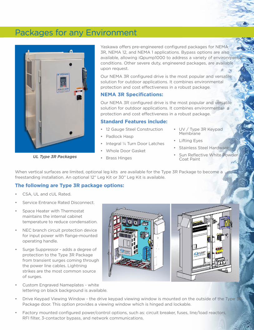
Packages for any Environment
Yaskawa offers pre-engineered configured packages for NEMA 3R, NEMA 12, and NEMA 1 applications. Bypass options are also available, allowing iQpump1000 to address a variety of environmental conditions. Other severe duty, engineered packages, are available upon request.
Our NEMA 3R configured drive is the most popular and versatile solution for outdoor applications. It combines environmental protection and cost effectiveness in a robust package.
NEMA 3R Specifications:
Our NEMA 3R configured drive is the most popular and versatile solution for outdoor applications. It combines environmental protection and cost effectiveness in a robust package.
Standard Features include:
When vertical surfaces are limited, optional leg kits are available for the Type 3R Package to become a freestanding installation. An optional 12” Leg Kit or 30” Leg Kit is available.
The following are Type 3R package options:
• CSA, UL and cUL Rated.
• Service Entrance Rated Disconnect.
• Space Heater with Thermostat - maintains the internal cabinet temperature to reduce condensation.
• NEC branch circuit protection device for input power with flange-mounted operating handle.
• Surge Suppressor - adds a degree of protection to the Type 3R Package from transient surges coming through the power line cables. Lightning strikes are the most common source of surges.
• Custom Engraved Nameplates - white lettering on black background is available.
• Drive Keypad Viewing Window - the drive keypad viewing window is mounted on the outside of the Type 3R Package door. This option provides a viewing window which is hinged and lockable.
• Factory mounted configured power/control options, such as: circuit breaker, fuses, line/load reactors, RFI filter, 3-contactor bypass, and network communications.
UL Type 3R Packages
• 12 Gauge Steel Construction
• Padlock Hasp
• Integral ¼ Turn Door Latches
• Whole Door Gasket
• Brass Hinges
• UV / Type 3R Keypad Membrane
• Lifting Eyes
• Stainless Steel Hardware
• Sun Reflective White Powder Coat Paint

8
OverviewThe most common applications are simplex (single pump) constant pressure and pump down level control. The iQpump1000 is an easy investment choice with preset application macros, dedicated pump control features, and pump system protection.
Simplex Pump System
Sleep Mode Minimum
Flow Protection
No Flow / Deadhead
Protection
Submersible Motor Thrust
Bearing Control
Automatic System Restart
Sleep Boost
Low and High Pressure
Feedback Detection
Impeller Anti-jam Protection
Constant Pressure with Well
Drawn Down Control
Power Loss Utility Start
Delay Timer
Loss of Prime (LOP) / Pump
Dry-Run Protection
Pre-Charge Control
(Controlled Pipe Fill)
APPLICATION REQUIREMENTS
Examples of Simplex Systems

9
Software Features
Sleep Mode Minimum Flow Protection Protects and shuts down the pump at low speeds or in low flow conditions. No Flow / Deadhead Protection Separate from Sleep Mode, this detects changes in pump motor RPM relative to sudden changes in pressure or flow. This protects against broken pipe, excessive well draw-down, or run-dry conditions. Submersible Motor Thrust Bearing Control Protects the bearings of submersible pump motors by ensuring proper start-up speeds and times. Automatic System Restart Programmable timers allow iQpump1000 to automatically restart the system in Auto Mode for faults relating to brown outs, loss of power, and pump specific faults. Sleep Boost Intended for use with a pressure tank, iQpump1000 boosts the set pressure prior to shutdown, extending the pump’s sleep time, reducing cycling, and saving energy. Low and High Pressure Feedback Detection iQpump1000 continuously monitors the system feedback device to provide a warning alarm or fault based on the programmed level. Impeller Anti-Jam Automatic Control Provides a method for the iQpump1000 to detect high current and attempt to expel corrosion or solids which are impeding the pump impeller. The system will perform a quick reversal to try and dislodge jam. Constant Pressure with Well Draw Down Control This function allows iQpump1000 to control constant pressure when there is adequate water in the well, while monitoring a second down hole transducer for water level. If the water level drops below user settings, iQpump1000 reduces pump speed to maximize well output. System will return automatically to normal operation when well water is recharged to an adequate level. Power Loss Utility Start Delay Timer Used in conjunction with “Automatic Restart”, a programmable timer will delay starting to allow for multiple pumps to sequence start on loss of power. This function ensures that the power system is not stressed when utility power has returned and pump system is automatically restarted. Loss of Prime (LOP) / Pump Dry-Run Protection Loss of prime protection is a feature to protect the pump and motor from damage caused by running the pump without water. If a pump were to lose prime and continue to operate without water moving through the pump, the pump would develop heat, which would eventually damage the pump seal, motor, pipe manifold and related components. Pre-Charge Control (Controlled Pipe Fill) This programmable feature eliminates water hammer and extends system life by gradually filling a pipeline before normal full pressure and flow operation. Pump motor speed can be controlled with a system timer, level or pressure control device to indicate when normal operation may begin.
20 HP Submersible Pump Control for Irrigation.

10
Drive with Constant Speed Lag Pump Multiplexing
Application Notes
• Automatically starts and stops up to 5 Lag pumps based on the system demand, and will automatically stage and de-stage the booster pumps.
• Alternation of lag pumps to provide even wear.
• Allows a single lag pump to be selected during Pre-Charge (Pipe Fill) to reduce fill rate time.
• For large water consumers, acer-feet can be selected for water accumulation units.
OverviewMany agricultural farms use multiple large verticle turbine pumps to provide pressurized water to large pivot irrigation systems. Applying a VFD to each of the booster pumps on these systems may not be practical. However, iQpump1000, using it’s on-board digital outputs, can control up to 5 lag pump starters from a single VFD to maintain pressure by staging and de-staging the lag pumps.
Inlet Suction Control
Speed Reduction “Go To Speed”
After Lag Pump Staging
Setpoint Boost After
De-staging
Low Flow and High Flow (GPM)
Protection
Flow Meter Data Logging
Lube Pump Control
Hard Current Limit
Back Spin Timer
APPLICATION REQUIREMENTS
11
Inlet Suction Control iQpump1000 when installed with an inlet suction transducer will monitor a suction pressure drop to a programmed suction pressure setpoint. The iQpump1000 seamlessly switches over and controls suction pressure to keep the system running efficiently. If the inlet pressure returns to the suction pressure setpoint at anytime, the iQpump1000 will switch back to controlling outlet pressure. A suction pressure alarm/fault detection is available If the suction pressure drops below the Low Suction Pressure Detection Level for more than the Low Suction Pressure Detection Time. Speed Reduction “Go To Speed” After Lag Pump Staging This feature will force the lead iQpump1000 VTC to operate at a lower fixed speed for a specified amount of time whenever a lag pump is staged on. This is to dampen the shock loading of a lag pump starting across the line to the system. Setpoint Boost After Destaging This feature will automatically boost the auto setpoint pressure to a new specified incremental amount for a programmable time whenever a pump is de-staged. This allows the lead iQpump1000 VTC to accelerate more quickly to lessen the pressure drop on the system of a lag pump that is being de-staged.
Low Flow and High Flow (GPM) Protection iQpump1000 continuously monitors the system flow signal feedback to provide a warning alarm or fault based on the programmed level. Flow Meter Data Logging Through a secondary analog or pulse train input, a flow sensor can be connected inline with the pump system back to iQpump1000 to read and accumulate total system flow to report to authorities. The system can be configured to detect “No Flow” and switch to “Sleep” on low demand. Lube Pump Control Designed for pumps that require pre-lubrication before each start. Digital output will energize a solenoid valve for a programmable time before starting allowing for lubrication each time the pump is started.
Hard Current Limit As the pump impeller wears over time, it changes the efficiency of the pump. Therefore, in order to maintain a constant presure or flow, the pump speed will increase, resulting in greater motor amps. This increase can cause the drive to trip on nuisance motor overload (OL). By setting in a hard motor current limit (not to exceed) the drive will reduce the output speed automatically keep the system running smoothly” to “as the impeller wears to keep the system from overloading.
Back Spin Timer After Stop or Hand command, the drive will not restart until timer expires allowing the water column to flow back down the well.
Software Features
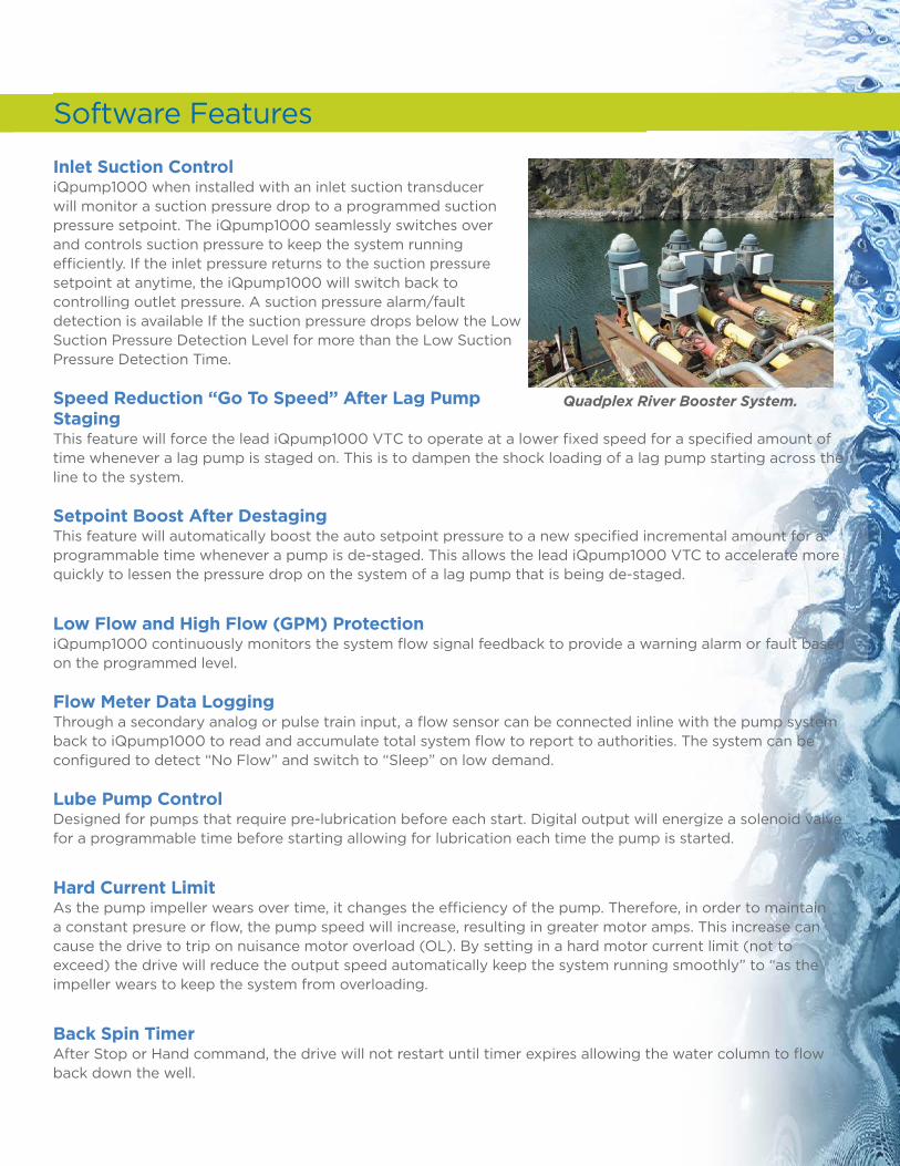
Quadplex River Booster System.
12
Drive to Drive Multiplexing
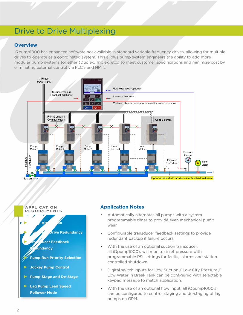
OverviewiQpump1000 has enhanced software not available in standard variable frequency drives, allowing for multiple drives to operate as a coordinated system. This allows pump system engineers the ability to add more modular pump systems together (Duplex, Triplex, etc.) to meet customer specifications and minimize cost by eliminating external control via PLC’s and HMI’s.
• Automatically alternates all pumps with a system programmable timer to provide even mechanical pump wear.
• Configurable transducer feedback settings to provide redundant backup if failure occurs.
• With the use of an optional suction transducer, all iQpump1000’s will monitor inlet pressure with programmable PSI settings for faults, alarms and station controlled shutdown.
• Digital switch inputs for Low Suction / Low City Pressure / Low Water in Break Tank can be configured with selectable keypad message to match application.
• With the use of an optional flow input, all iQpump1000’s can be configured to control staging and de-staging of lag pumps on GPM.
Application Notes
Pump Alternation
Pump and Drive Redundancy
Transducer Feedback
Redundancy
Pump Run Priority Selection
Jockey Pump Control
Pump Stage and De-Stage
Lag Pump Lead Speed
Follower Mode
APPLICATION REQUIREMENTS
13
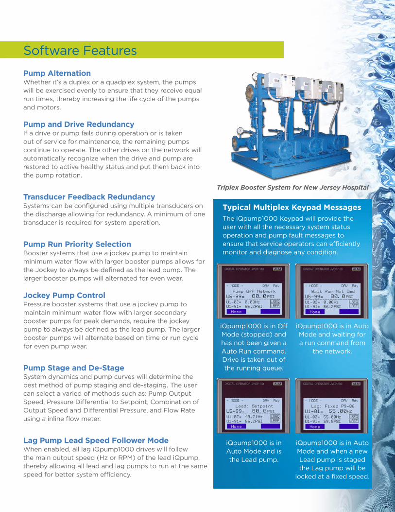
Typical Multiplex Keypad MessagesThe iQpump1000 Keypad will provide the user with all the necessary system status operation and pump fault messages to ensure that service operators can efficiently monitor and diagnose any condition.
iQpump1000 is in Auto Mode and is the Lead pump.
iQpump1000 is in Auto Mode and waiting for a run command from
the network.
iQpump1000 is in Auto Mode and when a new Lead pump is staged the Lag pump will be
locked at a fixed speed.
iQpump1000 is in Off Mode (stopped) and has not been given a Auto Run command. Drive is taken out of the running queue.
Software Features
Pump Alternation Whether it’s a duplex or a quadplex system, the pumps will be exercised evenly to ensure that they receive equal run times, thereby increasing the life cycle of the pumps and motors. Pump and Drive Redundancy If a drive or pump fails during operation or is taken out of service for maintenance, the remaining pumps continue to operate. The other drives on the network will automatically recognize when the drive and pump are restored to active healthy status and put them back into the pump rotation.
Transducer Feedback Redundancy Systems can be configured using multiple transducers on the discharge allowing for redundancy. A minimum of one transducer is required for system operation.
Pump Run Priority Selection Booster systems that use a jockey pump to maintain minimum water flow with larger booster pumps allows for the Jockey to always be defined as the lead pump. The larger booster pumps will alternated for even wear. Jockey Pump Control Pressure booster systems that use a jockey pump to maintain minimum water flow with larger secondary booster pumps for peak demands, require the jockey pump to always be defined as the lead pump. The larger booster pumps will alternate based on time or run cycle for even pump wear.
Pump Stage and De-Stage System dynamics and pump curves will determine the best method of pump staging and de-staging. The user can select a varied of methods such as: Pump Output Speed, Pressure Differential to Setpoint, Combination of Output Speed and Differential Pressure, and Flow Rate using a inline flow meter.
Lag Pump Lead Speed Follower Mode When enabled, all lag iQpump1000 drives will follow the main output speed (Hz or RPM) of the lead iQpump, thereby allowing all lead and lag pumps to run at the same speed for better system efficiency.
Triplex Booster System for New Jersey Hospital

14
Model Number Designation
Drive Ratings - 240V
CIMR- PW 2 A 0004 F A AAC Drive
iQpump1000 Series
Design Revision
No. Voltage Class
2A 3-phase, 240V
4A 3-phase, 480V
4T 6-phase, 12-pulse, 480V
5A 3-phase, 600V
No. Output Current Code (A)
See Following Charts
No. Enclosure Type
A IP00
F NEMA Type1
U Flange (Type 12 backside)
No. Environmental Specification
A Standard
240V, 3-Phase Input
Rated Output Amps
Nominal HP
Model Number
CIMR-PW
Variant
F = NEMA 1
A = Protected Chassis (IP00)
U = Flange (NEMA 12 Backside)
3.5 3/4 2A0004_AA F, U
6 1 2A0006_AA F, U
8 2 2A0008_AA F, U
9.6 3 2A0010_AA F, U
12 3 2A0012_AA F, U
17.5 5 2A0018_AA F, U
21 7.5 2A0021_AA F, U
30 10 2A0030_AA F, U
40 15 2A0040_AA F, U
56 20 2A0056_AA F, U
69 25 2A0069_AA F, U
81 30 2A0081_AA F, U
110 40 2A0110_AA F, U
138 50 2A0138_AA F, U
169 60 2A0169_AA F, U
211 75 2A0211_AA F, U
250 100 2A0250_AA A, U
312 125 2A0312_AA A, U
360 150 2A0360_AA A, U
415 175 2A0415_AA A, U
240V, 1-Phase Input 208-230V Three-Phase Output
Single Phase Input - Size Method A(A) (continuous full power)
Single Phase Input - Sizing Method B(B)
(86% max power of connected motor size)
Model Number
CIMR-PW
Variant
F = NEMA 1
A = Protected Chassis (IP00)
U = Flange (NEMA 12 Backside)
Without Additional Reactor
With Additional Reactor
Motor Amps
Motor Size (HP)
Motor Amps
Motor Size (HP)
Motor Amps
Motor Size (HP)
1.7 1/3 2.4 1/2 2.4 1/2 2A0004_AA F, U
3.5 3/4 3.5 3/4 4.6 1 2A0006_AA F, U
4.6 1 4.6 1 4.6 1 2A0008_AA F, U
4.6 1 4.6 1 6.6 1.5 2A0010_AA F, U
6.6 1.5 7.5 2 7.5 2 2A0012_AA F, U
7.5 2 10.6 3 10.6 3 2A0018_AA F, U
7.5 2 10.6 3 10.6 3 2A0021_AA F, U
10.6 3 10.6 3 17 5 2A0030_AA F, U
10.6 3 17 5 17 5 2A0040_AA F, U
17 5 24 7.5 24 7.5 2A0056_AA F, U
24 7.5 31 10 31 10 2A0069_AA F, U
31 10 46 15 46 15 2A0081_AA F, U
31 10 31 10 46 15 2A0110_AA F, U
46 15 46 15 59 20 2A0138_AA F, U
59 20 59 20 75 25 2A0169_AA F, U
75 25 75 25 88 30 2A0211_AA F, U
88 30 88 30 114 40 2A0250_AA A, U
114 40 114 40 143 50 2A0312_AA A, U
143 50 143 50 169 60 2A0360_AA A, U
169 60 169 60 211 75 2A0415_AA A, U
(A) Use single phase sizing method A for applications requiring more than 87% motor power (more than 95% speed for variable torque) for any length of time.
(B) Use single phase sizing method B for applications requiring no more than 87% motor power (no more than 95% speed for variable torque).
15
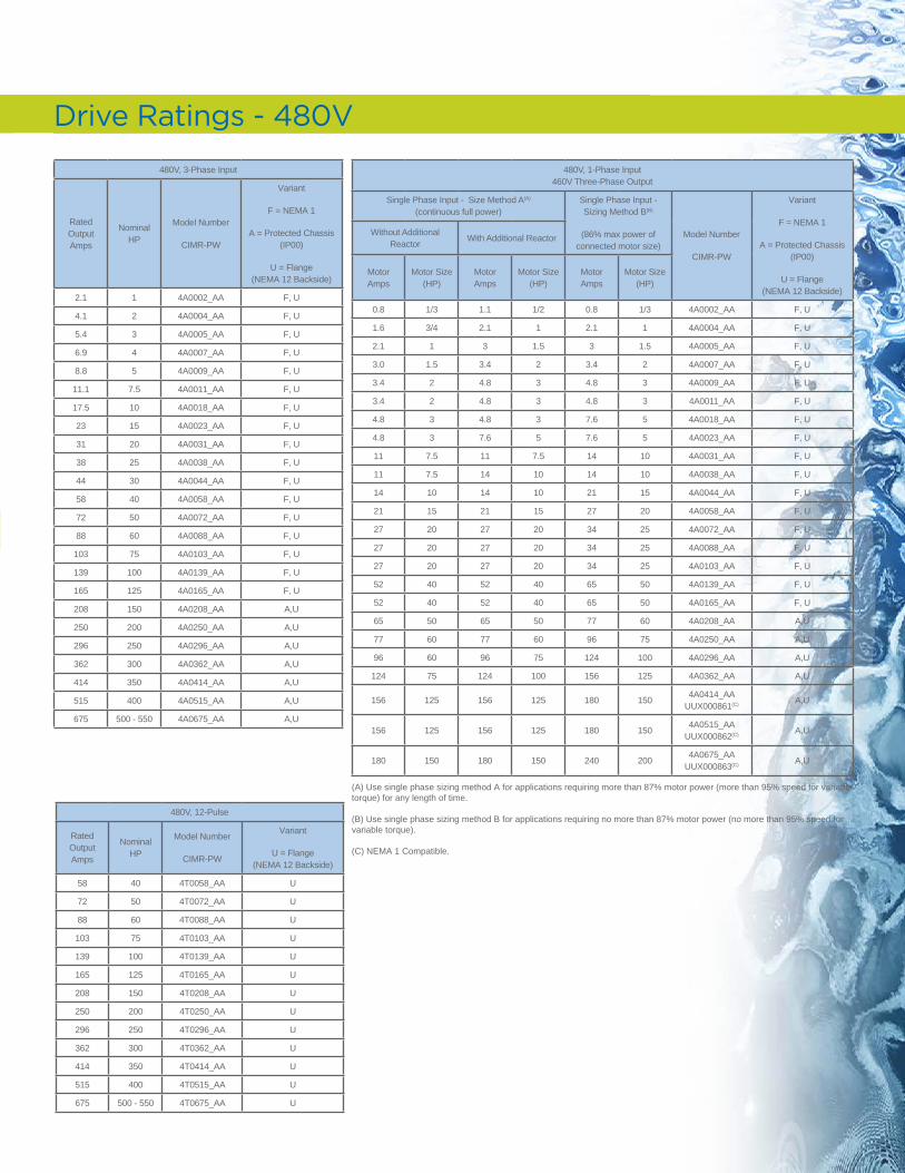
Drive Ratings - 480V
480V, 3-Phase Input
Rated Output Amps
Nominal HP
Model Number
CIMR-PW
Variant
F = NEMA 1
A = Protected Chassis (IP00)
U = Flange (NEMA 12 Backside)
2.1 1 4A0002_AA F, U
4.1 2 4A0004_AA F, U
5.4 3 4A0005_AA F, U
6.9 4 4A0007_AA F, U
8.8 5 4A0009_AA F, U
11.1 7.5 4A0011_AA F, U
17.5 10 4A0018_AA F, U
23 15 4A0023_AA F, U
31 20 4A0031_AA F, U
38 25 4A0038_AA F, U
44 30 4A0044_AA F, U
58 40 4A0058_AA F, U
72 50 4A0072_AA F, U
88 60 4A0088_AA F, U
103 75 4A0103_AA F, U
139 100 4A0139_AA F, U
165 125 4A0165_AA F, U
208 150 4A0208_AA A,U
250 200 4A0250_AA A,U
296 250 4A0296_AA A,U
362 300 4A0362_AA A,U
414 350 4A0414_AA A,U
515 400 4A0515_AA A,U
675 500 - 550 4A0675_AA A,U
480V, 1-Phase Input 460V Three-Phase Output
Single Phase Input - Size Method A(A) (continuous full power)
Single Phase Input - Sizing Method B(B)
(86% max power of connected motor size)
Model Number
CIMR-PW
Variant
F = NEMA 1
A = Protected Chassis (IP00)
U = Flange (NEMA 12 Backside)
Without Additional Reactor
With Additional Reactor
Motor Amps
Motor Size (HP)
Motor Amps
Motor Size (HP)
Motor Amps
Motor Size (HP)
0.8 1/3 1.1 1/2 0.8 1/3 4A0002_AA F, U
1.6 3/4 2.1 1 2.1 1 4A0004_AA F, U
2.1 1 3 1.5 3 1.5 4A0005_AA F, U
3.0 1.5 3.4 2 3.4 2 4A0007_AA F, U
3.4 2 4.8 3 4.8 3 4A0009_AA F, U
3.4 2 4.8 3 4.8 3 4A0011_AA F, U
4.8 3 4.8 3 7.6 5 4A0018_AA F, U
4.8 3 7.6 5 7.6 5 4A0023_AA F, U
11 7.5 11 7.5 14 10 4A0031_AA F, U
11 7.5 14 10 14 10 4A0038_AA F, U
14 10 14 10 21 15 4A0044_AA F, U
21 15 21 15 27 20 4A0058_AA F, U
27 20 27 20 34 25 4A0072_AA F, U
27 20 27 20 34 25 4A0088_AA F, U
27 20 27 20 34 25 4A0103_AA F, U
52 40 52 40 65 50 4A0139_AA F, U
52 40 52 40 65 50 4A0165_AA F, U
65 50 65 50 77 60 4A0208_AA A,U
77 60 77 60 96 75 4A0250_AA A,U
96 60 96 75 124 100 4A0296_AA A,U
124 75 124 100 156 125 4A0362_AA A,U
156 125 156 125 180 1504A0414_AA
UUX000861(C) A,U
156 125 156 125 180 1504A0515_AA
UUX000862(C) A,U
180 150 180 150 240 2004A0675_AA
UUX000863(C) A,U
(A) Use single phase sizing method A for applications requiring more than 87% motor power (more than 95% speed for variable torque) for any length of time.
(B) Use single phase sizing method B for applications requiring no more than 87% motor power (no more than 95% speed for variable torque).
(C) NEMA 1 Compatible.
480V, 12-Pulse
Rated Output Amps
Nominal HP
Model Number
CIMR-PW
Variant
U = Flange (NEMA 12 Backside)
58 40 4T0058_AA U
72 50 4T0072_AA U
88 60 4T0088_AA U
103 75 4T0103_AA U
139 100 4T0139_AA U
165 125 4T0165_AA U
208 150 4T0208_AA U
250 200 4T0250_AA U
296 250 4T0296_AA U
362 300 4T0362_AA U
414 350 4T0414_AA U
515 400 4T0515_AA U
675 500 - 550 4T0675_AA U

16
Drive Ratings - 600V
600V, 3-Phase Input
Rated Output Amps
Nominal HP
Model Number
CIMR-PW
Variant
F = NEMA 1
A = Protected Chassis (IP00)
U = Flange (NEMA 12 Backside)
2.7 1 & 2 5A0003_AA F, U
3.9 3 5A0004_AA F, U
6.1 5 5A0006_AA F, U
9 7.5 5A0009_AA F, U
11 10 5A0011_AA F, U
17.5 15 5A0017_AA F, U
22 20 5A0022_AA F, U
27 25 5A0027_AA F, U
32 30 5A0032_AA F, U
41 40 5A0041_AA F, U
52 50 5A0052_AA F, U
62 60 5A0062_AA F, U
77 75 5A0077_AA F, U
99 100 5A0099_AA F, U
125 125 5A0125_AA A, U
145 150 5A0145_AA A, U
192 200 5A0192_AA A, U
600V, 1-Phase Input 575V Three-Phase Output
Single Phase Input - Size Method A(A) (continuous full power)
Single Phase Input - Sizing Method B(B)
(86% max power of connected motor size)
Model Number
CIMR-PW
Variant
F = NEMA 1
A = Protected Chassis (IP00)
U = Flange (NEMA 12 Backside)
Without Additional Reactor
With Additional Reactor
Motor Amps
Motor Size (HP)
Motor Amps
Motor Size (HP)
Motor Amps
Motor Size (HP)
1.7 1 2.4 1.5 1.7 1 5A0003_AA F, U
2.4 1.5 2.7 2 2.7 2 5A0004_AA F, U
2.7 2 3.9 3 3.9 3 5A0006_AA F, U
3.9 3 6.1 5 6.1 5 5A0009_AA F, U
2.7 2 3.9 3 3.9 3 5A0011_AA F, U
6.1 5 6.1 5 9 7.5 5A0017_AA F, U
6.1 5 9 7.5 9 7.5 5A0022_AA F, U
9 7.5 11 10 11 10 5A0027_AA F, U
9 7.5 11 10 11 10 5A0032_AA F, U
17 15 17 15 22 20 5A0041_AA F, U
17 15 17 15 22 20 5A0052_AA F, U
27 25 27 25 32 30 5A0062_AA F, U
27 30 32 30 41 40 5A0077_AA F, U
32 30 32 30 41 40 5A0099_AA F, U
52 50 52 50 62 60 5A0125_AA A, U
52 50 52 50 62 60 5A0145_AA A, U
77 75 77 75 99 100 5A0192_AA A, U
77 75 77 75 99 100 5A0242_AA A, U
(A) Use single phase sizing method A for applications requiring more than 87% motor power (more than 95% speed for variable torque) for any length of time.
(B) Use single phase sizing method B for applications requiring no more than 87% motor power (no more than 95% speed for variable torque).
17
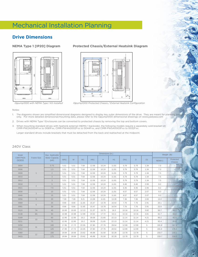
Mechanical Installation Planning
Drive Dimensions
NEMA Type 1 [IP20] Diagram Protected Chassis/External Heatsink Diagram
P1000 with NEMA Type 1 Kit Installed
HN
1
WN1 DN1
Notes:
1. The diagrams shown are simplified dimensional diagrams designed to display key outer dimensions of the drive. They are meant for planning purposes only. For more detailed dimensional/mounting data, please refer to the iQpump1000 dimensional drawings on www.yaskawa.com
2. Drives with NEMA Type 1 Enclosures can be converted to protected chassis by removing the top and bottom covers.
3. When mounting standard drives with heatsink external (NEMA 1 backside), the following models require a separately sold bracket kit: CIMR-PW2A0004Fxx to 0081Fxx, CIMR-PW4A0002Fxx to 0044Fxx, and CIMR-PW5A0003Fxx to 0032Fxx.
Larger standard drives include brackets that must be detached from the back and reattached at the midpoint.
240V Class
Model CIMR-PW2A oooo
Frame SizeMax. Applicable Motor Capacity
(HP)
Dimensions (in.) Weight (lb)
WN1 W W1 HN1 H H1 DN1 D D1 NEMA 1Protected Chassis
0004
1
0.75 5.51 5.51 7.64 12.06 10.24 11.81 5.79 5.79 1.34 7.3 --
0006 1.5 5.51 5.51 7.64 12.06 10.24 11.81 5.79 5.79 1.34 7.3 --
0008 2 5.51 5.51 7.64 12.06 10.24 11.81 5.79 5.79 1.34 7.5 --
0010 3 5.51 5.51 7.64 12.06 10.24 11.81 5.79 5.79 1.34 7.5 --
0012 3 5.51 5.51 7.64 12.06 10.24 11.81 5.79 5.79 1.34 7.5 --
00182
5 5.51 5.51 7.64 12.06 10.24 11.81 6.46 6.46 2.06 8.2 --
0021 7.5 5.51 5.51 7.64 12.06 10.24 11.81 6.46 6.46 2.06 8.2 --
00303
10 5.51 5.51 7.64 12.06 10.24 11.81 6.57 6.57 2.07 9.3 --
0040 15 5.51 5.51 7.64 12.06 10.24 11.81 6.57 6.57 2.07 9.3 --
0056 5 20 7.09 7.09 9.21 13.38 11.81 13.39 7.36 7.36 2.83 13.0 --
00696
25 8.66 8.66 11.65 15.47 13.78 16.54 7.76 7.76 2.91 20.1 --
0081 30 8.66 8.66 11.65 15.47 13.78 16.54 7.76 7.76 2.91 22.0 --
0110 7A 40 10.00 10.00 12.13 21.37 15.75 16.3 10.16 10.16 3.82 50.7 46.2
0138 8A 50 10.98 10.98 12.99 24.52 17.72 18.11 10.16 10.16 3.81 61.7 55.0
016910
60 12.95 12.95 15.2 30.08 21.65 22.13 11.14 11.14 4.21 90.2 81.4
0211 75 12.95 12.95 15.2 30.08 21.65 22.13 11.14 11.14 4.21 92.4 83.6
025011
100 17.95 17.72 22.05 37.80 27.76 28.54 12.99 12.99 5 191.8 167.6
0312 125 17.95 17.72 22.05 37.80 27.76 28.54 12.99 12.99 5 191.8 176.4
036012
150 19.84 19.69 23.62 45.98 31.50 32.28 13.78 13.78 5 233.7 216.1
0415 175 19.84 19.69 23.62 45.98 31.50 32.28 13.78 13.78 5 233.7 218.3
H1
H
WW1
DD1
P1000 Protected Chassis / External Heatsink ConfigurationiQpump1000 with NEMA Type 1 Kit Installed iQpump1000 Protected Chassis / External Heatsink Configuration
18
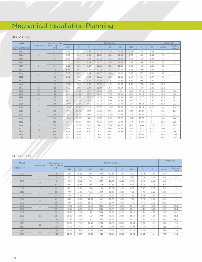
480V Class
Model
CIMR-PW4A ooooFrame Size
Max. Applicable Motor Capacity
(HP)
Dimensions (in.) Weight (lb)
WN1 W W1 HN1 H H1 DN1 D D1 NEMA 1 Protected Chassis
0002
1
1 5.51 5.51 7.64 12.06 10.24 11.81 5.79 5.79 1.34 7.3 --
0004 2 5.51 5.51 7.64 12.06 10.24 11.81 5.79 5.79 1.34 7.3 --
0005 3 5.51 5.51 7.64 12.06 10.24 11.81 5.79 5.79 1.34 7.3 --
0007
2
3 5.51 5.51 7.64 12.06 10.24 11.81 6.46 6.46 2.06 8.2 --
0009 5 5.51 5.51 7.64 12.06 10.24 11.81 6.46 6.46 2.06 8.2 --
0011 7.5 5.51 5.51 7.64 12.06 10.24 11.81 6.46 6.46 2.06 8.2 --
00183
10 5.51 5.51 7.64 12.06 10.24 11.81 6.57 6.57 2.07 9.3 --
0023 15 5.51 5.51 7.64 12.06 10.24 11.81 6.57 6.57 2.07 9.3 --
0031 4 20 7.09 7.09 9.21 13.38 11.81 13.39 6.88 6.88 2.04 12.5 --
0038 5 25 7.09 7.09 9.21 13.38 11.81 13.39 7.36 7.36 2.83 13.0 --
0044 6 30 8.66 8.66 11.65 15.47 13.78 16.54 7.76 7.76 2.91 20.1 --
0058 7B 40 10.37 10.37 12.13 18.65 15.75 16.3 10.16 10.16 3.82 50.6 50.60072 8B 50 11.35 11.35 12.99 20.62 17.72 18.11 10.16 10.16 3.81 59.4 59.40088
960 13.32 13.16 15.35 25.16 20.06 21.34 10.27 10.27 3.97 85.8 79.2
0103 75 13.32 13.16 15.35 25.16 20.06 21.34 10.27 10.27 3.97 85.8 79.2
013910
100 12.95 12.95 15.2 30.08 21.65 22.13 11.14 11.14 4.21 99.0 90.2
0165 125 12.95 12.95 15.2 30.08 21.65 22.13 11.14 11.14 4.21 101 92.4
0208 11 150 17.95 17.72 22.05 37.80 27.76 28.54 12.99 12.99 5 191 174
0250
12
200 19.84 19.69 23.62 45.98 31.50 32.28 13.78 13.78 5 233 211
0296 250 19.84 19.69 23.62 45.98 31.50 32.28 13.78 13.78 5 246 224
0362 300 19.84 19.69 23.62 45.98 31.50 32.28 13.78 13.78 5 257 235
0414 13 350 20.29 20.29 25.39 48.3 37.4 40.55 14.68 14.68 5.19 292 2750515
14450 26.86 26.86 31.97 61.3 44.88 46.38 14.72 14.72 7.71 504 475
0675 600 26.86 26.86 31.97 61.3 44.88 46.38 14.72 14.72 7.71 515 4860930
15800 50.2 49.61 -- 80.4 54.33 -- 14.73 14.91 -- 1394 1195
1200 1000 50.2 49.61 -- 80.4 54.33 -- 14.73 14.91 -- 1420 1221
600V Class
Model
CIMR-PW5A Frame Size
Max. Applicable Motor Capacity
(HP)
Dimensions (in.)Weight (lb)
WN1 W W1 HN1 H H1 DN1 D D1 NEMA 1 Protected Chassis
00031
2 5.51 5.51 7.64 12.06 10.24 11.81 5.79 5.79 1.34 7.3 --
0004 3 5.51 5.51 7.64 12.06 10.24 11.81 5.79 5.79 1.34 7.3 --
00062
5 5.51 5.51 7.64 12.06 10.24 11.81 6.46 6.46 2.06 8.2 --
0009 7.5 5.51 5.51 7.64 12.06 10.24 11.81 6.46 6.46 2.06 8.2 --
0011 3 10 5.51 5.51 7.64 12.06 10.24 11.81 6.57 6.57 2.07 9.3 --
00175
15 7.09 7.09 9.21 13.38 11.81 13.39 7.36 7.36 2.83 13.0 --
0022 20 7.09 7.09 9.21 13.38 11.81 13.39 7.36 7.36 2.83 13.0 --
00276
25 8.66 8.66 11.65 15.47 13.78 16.54 7.76 7.76 2.91 20.1 --
0032 30 8.66 8.66 11.65 15.47 13.78 16.54 7.76 7.76 2.91 20.1 --
00418B
40 11.35 11.35 12.99 20.62 17.72 18.11 10.16 10.16 3.81 59.4 59.40052 50 11.35 11.35 12.99 20.62 17.72 18.11 10.16 10.16 3.81 59.4 59.40062
10
60 12.95 12.95 15.2 30.08 21.65 22.13 11.14 11.14 4.21 99.0 90.2
0077 75 12.95 12.95 15.2 30.08 21.65 22.13 11.14 11.14 4.21 99.0 90.2
0099 100 12.95 12.95 15.2 30.08 21.65 22.13 11.14 11.14 4.21 99.0 90.2
012511
125 17.95 17.72 22.05 37.80 27.76 28.54 12.99 12.99 5 191 174
0145 150 17.95 17.72 22.05 37.80 27.76 28.54 12.99 12.99 5 191 174
019212
200 19.84 19.69 23.62 45.98 31.50 32.28 13.78 13.78 5 233 235
0242 250 19.84 19.69 23.62 45.98 31.50 32.28 13.78 13.78 5 257 235
Mechanical Installation Planning

19
Notes
This page intentionally left blank.

20
FOLD
Yaskawa America, Inc. Drives & Motion Division
2121 Norman Drive South Waukegan, IL 60085
1-800-YASKAWA (927-5292) • Local: 847-887-7000 • Fax: 1-847-887-7310
[email protected] • www.yaskawa.com
Document BL.iQp1000.01 01/15/13 • © 2013
We take quality personally at Yaskawa. Our drives and servo packages offer the highest MTBF in the world. The relationships we have with our customers ensure
mutual benefits. The partnerships we cultivate with our distributors add value to the way we work with you. We hire great people and continuously train them to be able
to serve your needs better. We deliver product on time. It works out of the box. We answer questions promptly and never say, “we can’t.”
To us, quality means doing everything we can to make our customer, partner, and employee experiences great.
We commit to that philosophy every day. We make it happen. We can because, to us, IT’S PERSONAL.