Embed Size (px)
Citation preview
Session Nine: Revisions to IEC 61508. What has Changes and What is the Impact for you?
2013 Safety Control & Instrumented Systems Conference 1
Session Nine:
Revisions to IEC61508, What has Changed and What is the Impact for You?
Ron Bell
Director, Engineering Safety Consultants
Abstract Over the past twenty-five years there have been a number of initiatives worldwide to develop guidelines and standards to enable the safe exploitation of programmable electronic systems used for safety applications. In the context of industrial applications (to distinguish from aerospace and military applications) a major initiative has been focused on IEC 61508, and other standards based on IEC 61508, which have emerged as key international standards.
This paper considers some of the key features of IEC 61508 (IEC 2000), which has now been available for over ten years, and indicates the main changes that have been incorporated into the new Edition 2 (IEC 2010a), published in April 2010.
1 Background
The International Electrotechnical Commission (IEC) set up a Task Group in 1985 to assess the viability of developing a generic standard for programmable electronic systems to be used for safety applications, the outcome of which was the setting up of a working group to develop an holistic, systems based, approach. A working group had previously been set up to deal with safety-related software. These two working groups collaborated on the development of an international standard that was to become IEC 61508 (IEC 2000).
The original scope of the Task Group (programmable electronic systems used for safety applications) was extended to include all types of electro-technical based technologies (electrical, electronic and programmable electronic systems (E/E/PE systems)).
Parts 1 to 7 of IEC 61508 were published during the period 1998-2000. In 2005 IEC/TR 61508-0 (IEC 2005) was published. A review process to update and improve the standard was initiated in 2002 and was completed with the publication of IEC 61508 Edition 2 (IEC 2010a) in April 2010.
Session Nine: Revisions to IEC 61508. What has Changes and What is the Impact for you?
2013 Safety Control & Instrumented Systems Conference 2
2 Structure of IEC 61508
The overall title of IEC 61508 is ‘Functional safety of electrical, electronic and programmable electronic (E/E/PE) safety-related systems’. The Parts are as listed in Table 1.
Table 1. The Parts of IEC 61508
Part Title
0 Functional safety and IEC 615081
1 General requirements
2 Requirements for electrical/electronic/programmable electronic safety-related systems
3 Software requirements
4 Definitions and abbreviations
5 Examples of methods for the determination of safety integrity levels
6 Guidelines on the application of parts 2 and 3
7 Overview of techniques and measures
Parts 1, 2, 3 contain all the normative requirements2 and some informative requirements. Parts 0, 5, 6 and 7 do not contain any normative requirements.
Parts 1, 2, 3 and 4 of IEC 61508 are IEC basic safety publications. One of the responsibilities of IEC Technical Committees is, wherever practicable, to make use of IEC 61508, in its role as a basic publication, in the preparation of their own sector or product standards that have E/E/PE safety-related systems within their scope.
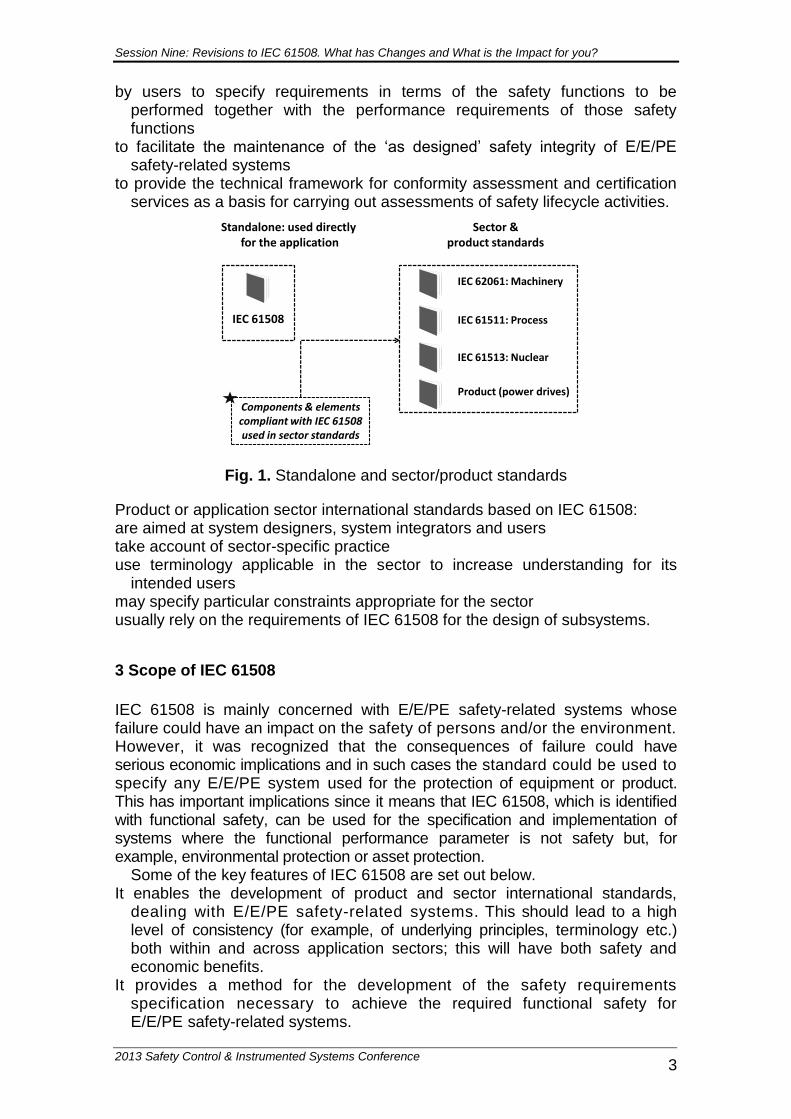
IEC 61508 is both a stand-alone standard and can also be used as the basis for sector and product standards. In its latter role, it has been used to develop standards for the process, nuclear and railway industries and for machinery and power drive systems. It has influenced, and will continue to influence, the development of E/E/PE safety-related systems and products across all sectors. This concept is illustrated in Figure 1.
The application of IEC 61508 as a standalone standard includes the use of the standard: as a set of general requirements for E/E/PE safety-related systems where no
application sector or product standards exist or where they are not appropriate
by suppliers of E/E/PE components and subsystems for use in all sectors (e.g. hardware and software of sensors, smart actuators, programmable controllers)
by system integrators to meet user specifications for E/E/PE safety-related systems
1 Part 0 has the status of a Technical Report and is purely informative. 2 In IEC standards a normative requirement is prefaced by ‘shall’ and if that requirement is relevant in the particular
application then it is necessary to comply with the requirement. A requirement prefaced by ‘should’ is informative and can
be considered as a recommendation but is not normative in respect of compliance to relevant requirements in the standard.
Session Nine: Revisions to IEC 61508. What has Changes and What is the Impact for you?
2013 Safety Control & Instrumented Systems Conference 3
by users to specify requirements in terms of the safety functions to be performed together with the performance requirements of those safety functions
to facilitate the maintenance of the ‘as designed’ safety integrity of E/E/PE safety-related systems
to provide the technical framework for conformity assessment and certification services as a basis for carrying out assessments of safety lifecycle activities.
Sector & product standards
Components & elementscompliant with IEC 61508 used in sector standards
Figure 1: Standalone & and sector/product standards
IEC 62061: Machinery
IEC 61511: Process
IEC 61513: Nuclear
Product (power drives)
IEC 61508
Standalone: used directly for the application
Fig. 1. Standalone and sector/product standards
Product or application sector international standards based on IEC 61508: are aimed at system designers, system integrators and users take account of sector-specific practice use terminology applicable in the sector to increase understanding for its
intended users may specify particular constraints appropriate for the sector usually rely on the requirements of IEC 61508 for the design of subsystems.
3 Scope of IEC 61508
IEC 61508 is mainly concerned with E/E/PE safety-related systems whose failure could have an impact on the safety of persons and/or the environment. However, it was recognized that the consequences of failure could have serious economic implications and in such cases the standard could be used to specify any E/E/PE system used for the protection of equipment or product. This has important implications since it means that IEC 61508, which is identified with functional safety, can be used for the specification and implementation of systems where the functional performance parameter is not safety but, for example, environmental protection or asset protection.
Some of the key features of IEC 61508 are set out below. It enables the development of product and sector international standards,
dealing with E/E/PE safety-related systems. This should lead to a high level of consistency (for example, of underlying principles, terminology etc.) both within and across application sectors; this will have both safety and economic benefits.
It provides a method for the development of the safety requirements specification necessary to achieve the required functional safety for E/E/PE safety-related systems.
Session Nine: Revisions to IEC 61508. What has Changes and What is the Impact for you?
2013 Safety Control & Instrumented Systems Conference 4
It uses safety integrity levels (SILs) for specifying the target level of safety integrity for the safety functions to be implemented by the E/E/PE safety-related systems.
It adopts a risk-based approach for the determination of the safety integrity level requirements.
It sets numerical target failure measures for E/E/PE safety-related systems that are linked to the safety integrity levels.
It sets a lower limit on the target failure measures, in a dangerous mode of failure, that can be claimed for a single E/E/PE safety-related system. For E/E/PE safety-related systems operating in: a low demand mode of operation, the lower limit is set at an average
probability of failure of 10–5 to perform its design function on demand a high demand or continuous mode of operation, the lower limit is set at a
average frequency of dangerous failure of 10 –9 per hour.
4 Concept of functional safety
Safety is defined as the freedom from unacceptable risk of physical injury or of damage to the health of people, either directly or indirectly, as a result of damage to property or to the environment.
Functional safety is part of the overall safety that depends on a system or equipment operating correctly in response to its inputs. For example, activation of a level switch in a tank containing a flammable liquid, which causes a valve to close and prevent flammable liquid from entering the tank, is an instance of functional safety.
5 Strategy to achieve functional safety
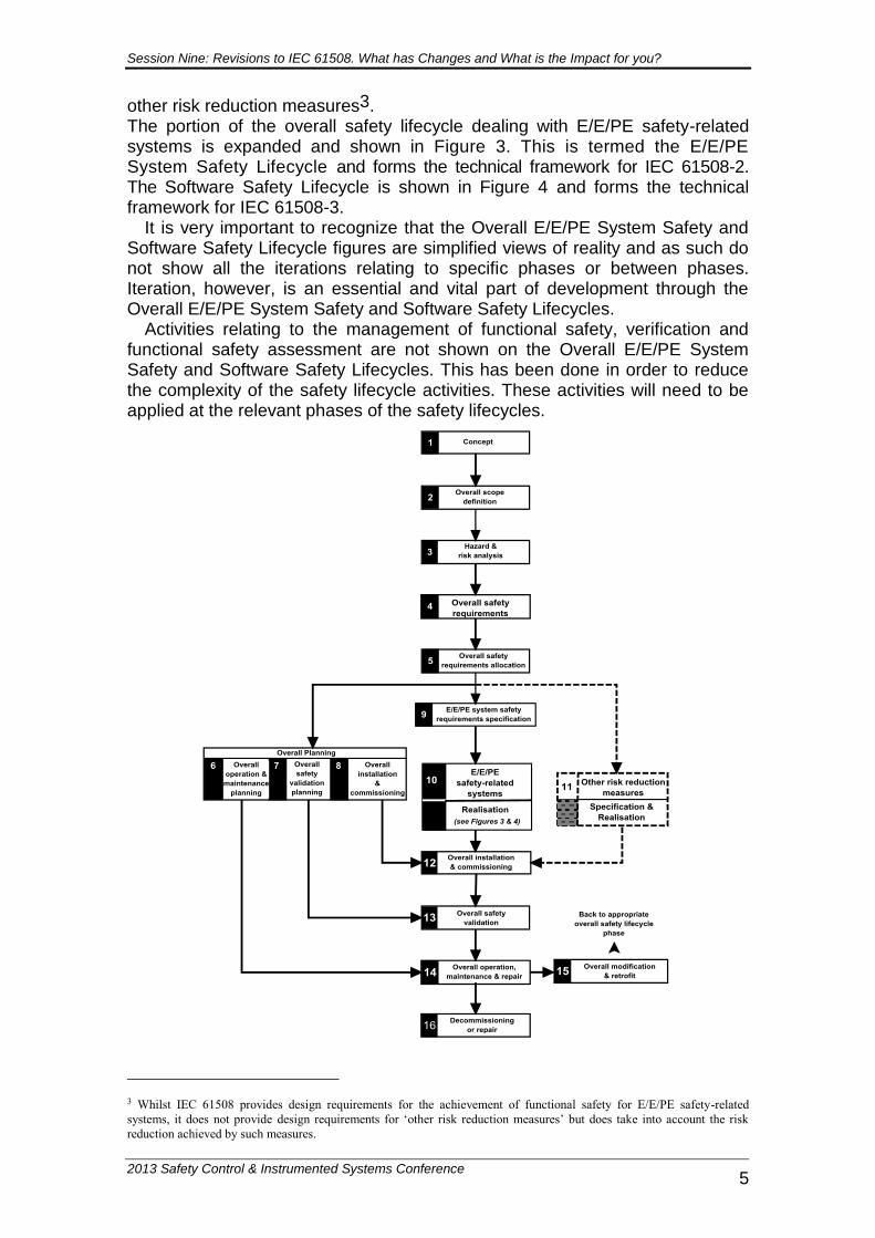
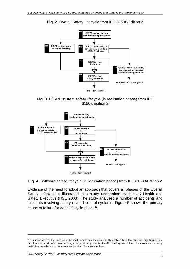
The strategy for achieving functional safety is made up of the following key elements: management of functional safety technical requirements for relevant phases of the applicable safety lifecycles Functional Safety Assessment (FSA) competence of persons. IEC 61508 uses three safety lifecycles in order that all relevant phases are addressed: the Overall Safety Lifecycle (see Figure 2) the E/E/PE System Safety Lifecycle (see Figure 3) the Software Safety Lifecycle (see Figure 4). In order to deal in a systematic manner with all the activities necessary to achieve the required safety integrity for the E/E/PE safety-related systems, IEC 61508 adopts the Overall Safety Lifecycle indicated in Figure 3 (IEC 61508/Edition 2 shown) as the technical framework. The Overall Safety Lifecycle specified in IEC 61508 should be used as a basis for claiming conformance to the standard, but a different Overall Safety Lifecycle can be used to that given in Figure 3, providing the objectives and requirements of each clause of the standard are met.
The overall safety lifecycle encompasses the following risk reduction model: E/E/PE safety-related systems
Session Nine: Revisions to IEC 61508. What has Changes and What is the Impact for you?
2013 Safety Control & Instrumented Systems Conference 5
other risk reduction measures3. The portion of the overall safety lifecycle dealing with E/E/PE safety-related systems is expanded and shown in Figure 3. This is termed the E/E/PE System Safety Lifecycle and forms the technical framework for IEC 61508-2. The Software Safety Lifecycle is shown in Figure 4 and forms the technical framework for IEC 61508-3.
It is very important to recognize that the Overall E/E/PE System Safety and Software Safety Lifecycle figures are simplified views of reality and as such do not show all the iterations relating to specific phases or between phases. Iteration, however, is an essential and vital part of development through the Overall E/E/PE System Safety and Software Safety Lifecycles.
Activities relating to the management of functional safety, verification and functional safety assessment are not shown on the Overall E/E/PE System Safety and Software Safety Lifecycles. This has been done in order to reduce the complexity of the safety lifecycle activities. These activities will need to be applied at the relevant phases of the safety lifecycles.
3 Whilst IEC 61508 provides design requirements for the achievement of functional safety for E/E/PE safety-related
systems, it does not provide design requirements for ‘other risk reduction measures’ but does take into account the risk
reduction achieved by such measures.
Session Nine: Revisions to IEC 61508. What has Changes and What is the Impact for you?
2013 Safety Control & Instrumented Systems Conference 6
Fig. 2. Overall Safety Lifecycle from IEC 61508/Edition 2
Fig. 3. E/E/PE system safety lifecycle (in realisation phase) from IEC 61508/Edition 2
Fig. 4. Software safety lifecycle (in realisation phase) from IEC 61508/Edition 2
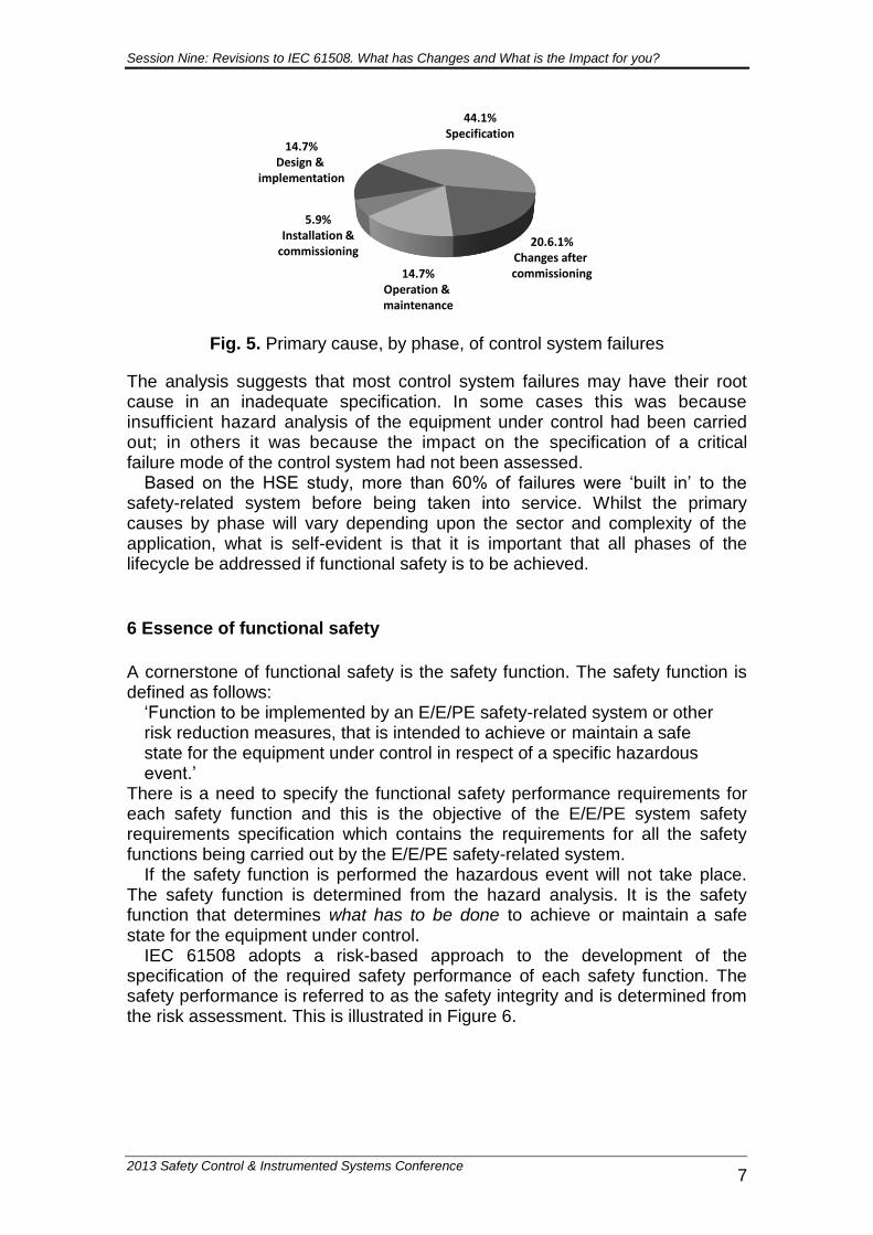
Evidence of the need to adopt an approach that covers all phases of the Overall Safety Lifecycle is illustrated in a study undertaken by the UK Health and Safety Executive (HSE 2003). The study analyzed a number of accidents and incidents involving safety-related control systems. Figure 5 shows the primary
cause of failure for each lifecycle phase4.
4 It is acknowledged that because of the small sample size the results of the analysis have low statistical significance, and
therefore care needs to be taken in using these results to generalise for all control system failures. Even so, there are many
useful lessons to be learned from summaries of incidents such as these.
Session Nine: Revisions to IEC 61508. What has Changes and What is the Impact for you?
2013 Safety Control & Instrumented Systems Conference 7
44.1%Specification
5.9%Installation &
commissioning20.6.1%
Changes after commissioning14.7%
Operation & maintenance
14.7%Design &
implementation
Figure 2: Primary cause, by phase, of control system failures
Fig. 5. Primary cause, by phase, of control system failures
The analysis suggests that most control system failures may have their root cause in an inadequate specification. In some cases this was because insufficient hazard analysis of the equipment under control had been carried out; in others it was because the impact on the specification of a critical failure mode of the control system had not been assessed.
Based on the HSE study, more than 60% of failures were ‘built in’ to the safety-related system before being taken into service. Whilst the primary causes by phase will vary depending upon the sector and complexity of the application, what is self-evident is that it is important that all phases of the lifecycle be addressed if functional safety is to be achieved.
6 Essence of functional safety
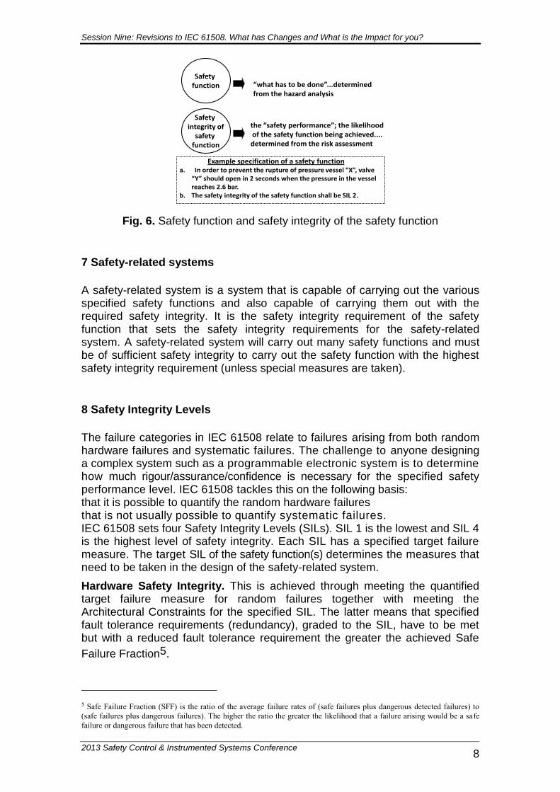
A cornerstone of functional safety is the safety function. The safety function is defined as follows:
‘Function to be implemented by an E/E/PE safety-related system or other risk reduction measures, that is intended to achieve or maintain a safe state for the equipment under control in respect of a specific hazardous event.’
There is a need to specify the functional safety performance requirements for each safety function and this is the objective of the E/E/PE system safety requirements specification which contains the requirements for all the safety functions being carried out by the E/E/PE safety-related system.
If the safety function is performed the hazardous event will not take place. The safety function is determined from the hazard analysis. It is the safety function that determines what has to be done to achieve or maintain a safe state for the equipment under control.
IEC 61508 adopts a risk-based approach to the development of the specification of the required safety performance of each safety function. The safety performance is referred to as the safety integrity and is determined from the risk assessment. This is illustrated in Figure 6.
Session Nine: Revisions to IEC 61508. What has Changes and What is the Impact for you?
2013 Safety Control & Instrumented Systems Conference 8
“what has to be done”...determined from the hazard analysis
Safety integrity of
safety function
the “safety performance”; the likelihoodof the safety function being achieved.... determined from the risk assessment
Safety function
Figure 3: Safety function & safety integrity of the safety function
Example specification of a safety function a. In order to prevent the rupture of pressure vessel “X”, valve
“Y” should open in 2 seconds when the pressure in the vessel reaches 2.6 bar.
b. The safety integrity of the safety function shall be SIL 2.
Fig. 6. Safety function and safety integrity of the safety function
7 Safety-related systems
A safety-related system is a system that is capable of carrying out the various specified safety functions and also capable of carrying them out with the required safety integrity. It is the safety integrity requirement of the safety function that sets the safety integrity requirements for the safety-related system. A safety-related system will carry out many safety functions and must be of sufficient safety integrity to carry out the safety function with the highest safety integrity requirement (unless special measures are taken).
8 Safety Integrity Levels
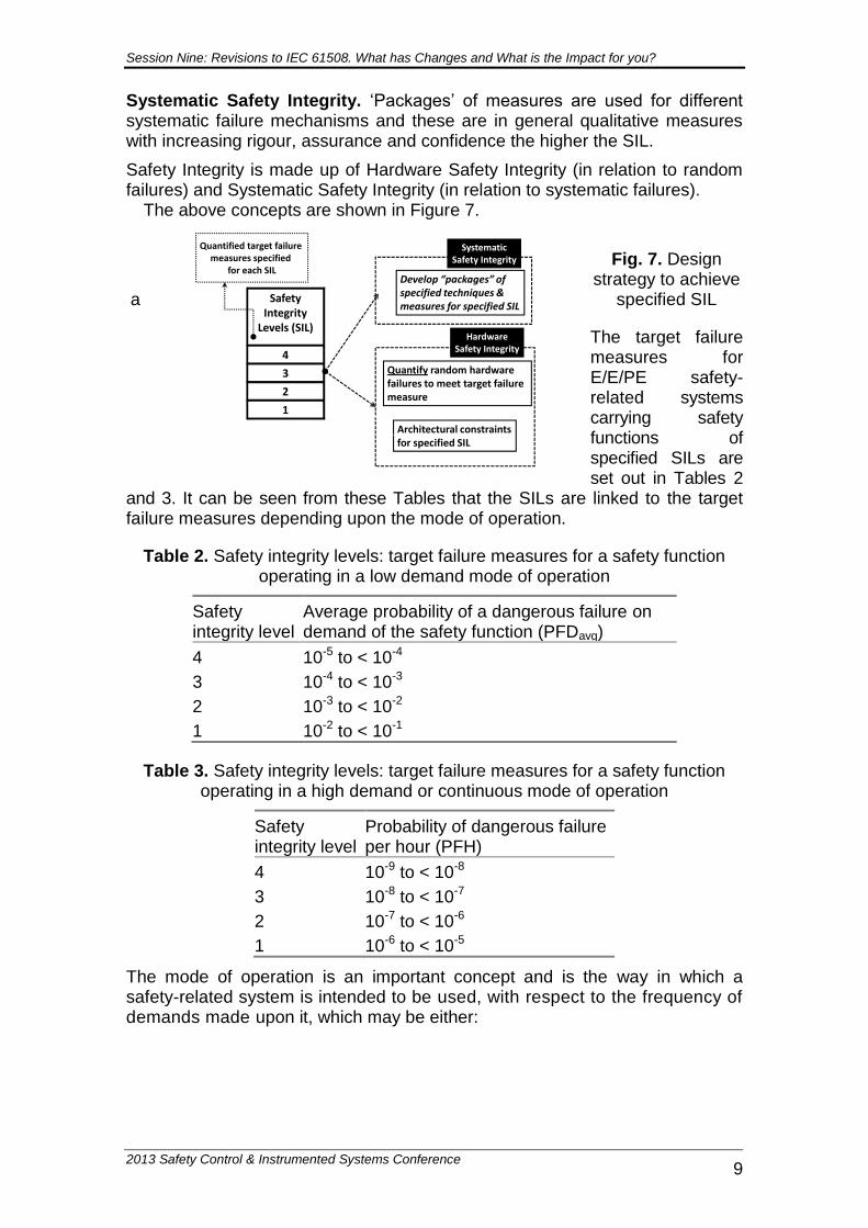
The failure categories in IEC 61508 relate to failures arising from both random hardware failures and systematic failures. The challenge to anyone designing a complex system such as a programmable electronic system is to determine how much rigour/assurance/confidence is necessary for the specified safety performance level. IEC 61508 tackles this on the following basis: that it is possible to quantify the random hardware failures that is not usually possible to quantify systematic failures. IEC 61508 sets four Safety Integrity Levels (SILs). SIL 1 is the lowest and SIL 4 is the highest level of safety integrity. Each SIL has a specified target failure measure. The target SIL of the safety function(s) determines the measures that need to be taken in the design of the safety-related system.
Hardware Safety Integrity. This is achieved through meeting the quantified target failure measure for random failures together with meeting the Architectural Constraints for the specified SIL. The latter means that specified fault tolerance requirements (redundancy), graded to the SIL, have to be met but with a reduced fault tolerance requirement the greater the achieved Safe
Failure Fraction5.
5 Safe Failure Fraction (SFF) is the ratio of the average failure rates of (safe failures plus dangerous detected failures) to
(safe failures plus dangerous failures). The higher the ratio the greater the likelihood that a failure arising would be a safe
failure or dangerous failure that has been detected.
Session Nine: Revisions to IEC 61508. What has Changes and What is the Impact for you?
2013 Safety Control & Instrumented Systems Conference 9
Figure 4: Design strategy to achieve a specified SIL
HardwareSafety Integrity
Architectural constraintsfor specified SIL
Quantify random hardware failures to meet target failure measure
1
2
3
4
Safety Integrity
Levels (SIL)
Quantified target failure measures specified
for each SIL
SystematicSafety Integrity
Develop “packages” ofspecified techniques & measures for specified SIL
Systematic Safety Integrity. ‘Packages’ of measures are used for different systematic failure mechanisms and these are in general qualitative measures with increasing rigour, assurance and confidence the higher the SIL.
Safety Integrity is made up of Hardware Safety Integrity (in relation to random failures) and Systematic Safety Integrity (in relation to systematic failures).
The above concepts are shown in Figure 7.
Fig. 7. Design strategy to achieve
a specified SIL
The target failure measures for E/E/PE safety-related systems carrying safety functions of specified SILs are set out in Tables 2
and 3. It can be seen from these Tables that the SILs are linked to the target failure measures depending upon the mode of operation.
Table 2. Safety integrity levels: target failure measures for a safety function operating in a low demand mode of operation
Safety integrity level
Average probability of a dangerous failure on demand of the safety function (PFDavg)
4 10-5 to < 10-4
3 10-4 to < 10-3
2 10-3 to < 10-2
1 10-2 to < 10-1
Table 3. Safety integrity levels: target failure measures for a safety function operating in a high demand or continuous mode of operation
Safety integrity level
Probability of dangerous failure per hour (PFH)
4 10-9 to < 10-8
3 10-8 to < 10-7
2 10-7 to < 10-6
1 10-6 to < 10-5
The mode of operation is an important concept and is the way in which a safety-related system is intended to be used, with respect to the frequency of demands made upon it, which may be either:
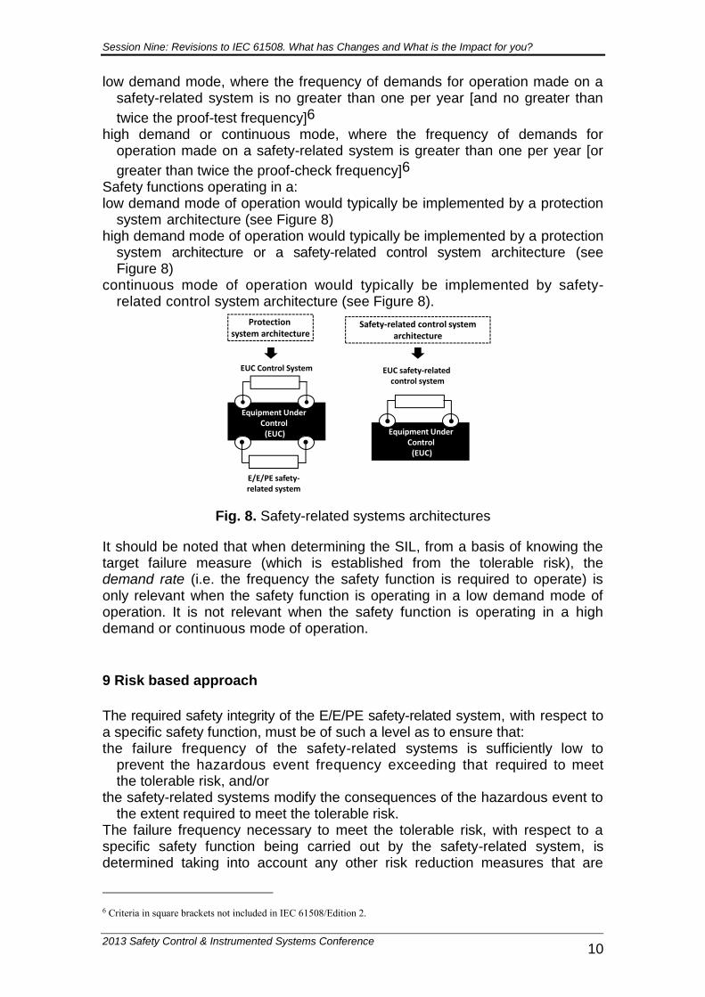
Session Nine: Revisions to IEC 61508. What has Changes and What is the Impact for you?
2013 Safety Control & Instrumented Systems Conference 10
low demand mode, where the frequency of demands for operation made on a safety-related system is no greater than one per year [and no greater than
twice the proof-test frequency]6 high demand or continuous mode, where the frequency of demands for
operation made on a safety-related system is greater than one per year [or
greater than twice the proof-check frequency]6 Safety functions operating in a: low demand mode of operation would typically be implemented by a protection
system architecture (see Figure 8) high demand mode of operation would typically be implemented by a protection
system architecture or a safety-related control system architecture (see Figure 8)
continuous mode of operation would typically be implemented by safety-related control system architecture (see Figure 8).
Protection system architecture
Equipment Under Control
(EUC)
E/E/PE safety-related system
EUC Control System
Safety-related control system architecture
EUC safety-related control system
Equipment Under Control
(EUC)
Figure 5: Safety-related system architectures
Fig. 8. Safety-related systems architectures
It should be noted that when determining the SIL, from a basis of knowing the target failure measure (which is established from the tolerable risk), the demand rate (i.e. the frequency the safety function is required to operate) is only relevant when the safety function is operating in a low demand mode of operation. It is not relevant when the safety function is operating in a high demand or continuous mode of operation.
9 Risk based approach
The required safety integrity of the E/E/PE safety-related system, with respect to a specific safety function, must be of such a level as to ensure that: the failure frequency of the safety-related systems is sufficiently low to
prevent the hazardous event frequency exceeding that required to meet the tolerable risk, and/or
the safety-related systems modify the consequences of the hazardous event to the extent required to meet the tolerable risk.
The failure frequency necessary to meet the tolerable risk, with respect to a specific safety function being carried out by the safety-related system, is determined taking into account any other risk reduction measures that are
6 Criteria in square brackets not included in IEC 61508/Edition 2.
Session Nine: Revisions to IEC 61508. What has Changes and What is the Impact for you?
2013 Safety Control & Instrumented Systems Conference 11
properly designed on functional safety criteria and properly managed throughout the life of the equipment.
The determination of this failure frequency, with respect to a specified safety function, allows the target failure measure to be determined and then the SIL to be established (from the target failure measure specified for each SIL in Table 2 or Table 3). The determination of the SIL for a specified safety function then allows the design process for the E/E/PE safety-related system to proceed (see Figure 7).
10 Revision of IEC 61508
As indicated in Section 1 of this paper, the review process to update and improve the standard was initiated in 2002 and was completed with the
publication of IEC 61508 Edition 2 (IEC 2010a) in April 20107. This section provides a summary of the revision process.
The procedure for revising an IEC standard is as follows: 1. Request from National Committees their views on the standard. 2. Based on the views of National Committees, prepare a Committee Draft (CD)
and distribute to National Committees for their comments. 3. Assess National Committee comments from the CD consultation, prepare
Committee Draft for Vote (CDV) and distribute to National Committees for vote.
4. If the voting results from the CDV consultation reach the required acceptance criteria, prepare Final Committee Draft International Standard (FDIS).
5. If the voting results from the FDIS voting exercise achieve the required acceptance criteria then the standard can be prepared for publication.
A key consideration during the revision process has been the need to ensure that any changes proposed added real value to the standard and to balance any perceived benefits made to the standard against the economic costs to users of the standard of implementing the changes.
Some of the key changes are considered below. Further information on IEC 61508 including Frequently Asked Question on Editions 1 and 2 can be found on the IEC website (IEC 2010e). IEC 61508 Standards+ version (IEC 2010f) was also issued in April 2010 and: shows the revisions referenced to Edition 1 provides hyperlinked notes explaining the changes. This facility should prove
particularly useful for those currently using IEC 61508/Edition 1.
10.1 Terminology
There have been several important changes to the definitions and it is important that where changes have been made they are examined to assess the implications since the change may affect the interpretation as understood in IEC 61508/Edition 1.
For example, the term subsystem was not a defined term in IEC 61508/Edition 1 but the usage of the term was not consistent; in IEC
7 Parts 1-7 have been revised. Part 0 is currently planned for revision, beginning in 2010.
Session Nine: Revisions to IEC 61508. What has Changes and What is the Impact for you?
2013 Safety Control & Instrumented Systems Conference 12
61508/Edition 2 this is a defined term. A key feature of the definition is that a dangerous failure of the subsystem, with respect to a specified safety function, will result in the failure of the safety function. It should also be noted that for correct usage of the term it will be necessary to have knowledge of the dangerous failures associated with the specified safety function. That is, there is a need to know the application or specify the assumptions on which the dangerous failures are based in order to determine, for example, whether an element is also a subsystem.
Other examples of key definitions that have been changed or are new include dangerous failure, safe failure, element and element safety function.
10.2 Architectural constraints
There are two possible Routes to compliance: Route 1H, based on hardware fault tolerance and safe failure fraction concepts; Route 2H, based on component reliability data from field feedback, increased
confidence levels and hardware fault tolerance for specified safety integrity levels.
There have been changes to the way in which Route 1H is applied and together with changes to the definitions of safe and dangerous failures, some differences in the calculation of safe failure fraction may arise compared to the method specified in IEC 61508/Edition 1.
Route 2H is a new concept for IEC 61508 and if Route 2H is selected then clause 7.4.4.3.1 of the standard specifies the requirements as follows: a hardware fault tolerance of 2 for a specified safety function of SIL 4 unless
the conditions in clause 7.4.4.3.2 apply a hardware fault tolerance of 1 for a specified safety function of SIL 3 unless
the conditions in clause 7.4.4.3.2 apply a hardware fault tolerance of 1 for a specified safety function of SIL 2, operating
in a high demand or continuous mode of operation, unless the conditions in clause 7.4.4.3.2 apply
a hardware fault tolerance of 0 for a specified safety function of SIL 2 operating in a low demand mode of operation
a hardware fault tolerance of 0 for a specified safety function of SIL 1. Clause 7.4.4.3.2 specifies, for type A elements only, if it is determined that by following the HFT requirements specified in 7.4.4.3.1, for the situation where an HFT greater than 0 is required, additional failures would be introduced and lead to a decrease in the overall safety of the EUC, then a safer alternative architecture with reduced HFT may be implemented. In such a case this shall be justified and documented. The justification shall provide evidence that: following the requirements in 7.4.4.3.1 would introduce additional failures and
would lead to a decrease in overall safety of the EUC, and if the HFT is reduced to 0 the failure modes, in the element carrying out the
safety function, can be excluded because the associated dangerous failure rates are very low compared to the target failure measure for the safety function under consideration. That is, the sum of the dangerous failure frequencies of all serial elements, on which fault exclusion is being claimed, should not exceed 1% of the target failure measure. Furthermore the applicability of fault exclusions shall be justified considering the potential for systematic faults.
Session Nine: Revisions to IEC 61508. What has Changes and What is the Impact for you?
2013 Safety Control & Instrumented Systems Conference 13
A note indicates that HFT is the preferred solution to achieve the required confidence that a robust architecture has been achieved.
If Route 2H is selected then reliability data used for quantifying the effect of random hardware failures shall: be based on field feedback be collected in accordance with published standards be evaluated to estimate uncertainty levels address the data uncertainties when calculating the target failure measure improve the system until there is a confidence greater than 90% that the target
failure measure has been achieved. All type B elements used in Route 2H shall have, as a minimum, a diagnostic coverage of not less than 60 %.
10.3 Modes of operation
The criteria relating to when a safety function is operating in a low demand mode of operation or a high demand/continuous mode of operation have been changed: the requirements relating to the proof test frequency have been removed.
10.4 Systematic safety integrity
There are three possible Routes to compliance: Route 1S, requirements for the avoidance (prevention) and requirements for the
control of systematic faults8
Route 2S, evidence that the equipment is ‘proven in use’ (PIU) 8 Route 3S, for pre-existing software elements only. For compliance with IEC 61508-2 it is necessary to meet the requirements of Route 1S or Route 2S, and for pre-existing software elements, Route 3S.
10.5 Systematic Capability
Systematic Capability is defined as ‘a measure (expressed on a scale of SC 1 to SC 4) of the confidence that the systematic safety integrity of an element meets the requirements of the specified SIL, in respect of the specified element safety function’.
Additionally, the concept of synthesis of elements with defined Systematic Capability has been developed. This would allow two elements meeting the requirements of Systematic Capability of SC 1 (for example) to be considered as a composite element of systematic capability of SC 2 but is conditional on there being ‘sufficient independence’ between the two elements.
8 This covers both hardware and software.
Session Nine: Revisions to IEC 61508. What has Changes and What is the Impact for you?
2013 Safety Control & Instrumented Systems Conference 14
10.6 Security
Malevolent and unauthorized actions have to be addressed during the hazard and risk analysis. If a security threat is seen as being reasonably foreseeable, then a security threats analysis should be carried out and if security threats have been identified then a vulnerability analysis should be undertaken in order to specify security requirements.
The rationale for this policy is that other IEC/ISO standards will be referenced that address this subject in depth.
10.7 E/E/PE requirements specification
The E/E/PE requirements specification in the current Edition of IEC 61508 comprised a single specification (i.e. a single step process). Two specifications are proposed (i.e. a two step process): Step 1: develop the E/E/PE system safety requirements specification (in IEC
61508-1) Step 2: develop the E/E/PE system design requirements specification (in IEC
61508-2).
10.8 Digital communications
The proposed requirements have been further elaborated and now comprise the concept of White and Black Channel architectures. Briefly: in White Channel architectures the entire communication channel (including
protocol, services & network components) have to comply with IEC 61508 and either IEC 61784-3 (IEC 2010b) or IEC 62280 (IEC 2010c and 2010d)
in Black Channel architectures, the interfaces have to comply with IEC 61784-3 or IEC 62280 (including services & protocols).
10.9 Management of functional safety
The clause has been restructured and now provides more comprehensive normative requirements, including: appointment of one or more persons by an organisation with responsibility for
one or more phases necessary for the achievement of functional safety of an E/E/PE safety-related system
identification of all persons undertaking defined activities relevant to the achievement of functional safety of an E/E/PE safety-related system
all those persons undertaking defined activities relevant to the achievement of functional safety of an E/E/PE safety-related system shall be competent for
the duties they have to perform9.
9 This change in the competence requirements in IEC 61508/Edition 2 extends the normative requirements for competence
across all safety lifecycle activities. In IEC 61508/Edition 1, the normative requirement for competence was restricted to the
Functional Safety Assessment activity.
Session Nine: Revisions to IEC 61508. What has Changes and What is the Impact for you?
2013 Safety Control & Instrumented Systems Conference 15
10.10 ASICS and integrated circuits
Requirements for ASICs are now included: an appropriate group of techniques and measures shall be used that are
essential to prevent the introduction of faults during the design and development of ASICs
techniques and measures that support the achievement of relevant properties are given in an informative Annex
special architectural requirements for integrated circuits (ICs) with on-chip redundancy are given in a normative Annex.
10.11 Safety manual for compliant items
The proposed revision sets out requirements for suppliers of products who claim compliance with the standard. The purpose of the safety manual for compliant items is to document all the information, relating to a compliant item, which is required to enable the integration of the compliant item into a safety-related system, or a subsystem or element, in compliance with the requirements of the standard.
Producers have to provide a safety manual for each compliant item they supply and for which they claim compliance with IEC 61508. The supplier is required to document a justification for all the information in the safety manual.
It should be noted that failure modes can only be classified as being safe or dangerous when the application of the compliant item is known and the following is stated to highlight this fact:
‘No claims shall be made in the safety manual, in respect of the hardware fault tolerance or the safe failure fraction or any other functional safety characteristic that is dependent on knowledge of safe and dangerous failure modes, unless the underlying assumptions, as to what constitute safe and dangerous failure modes, are clearly specified.’
10.12 Software
The following are the key changes to IEC 61508-3 (software): the introduction of the idea of desirable properties (such as completeness,
correctness and predictability) for the output of each lifecycle phase provision of extended requirement for the selection and justification of software
development tools allowing software elements which were not originally developed with safety in
mind to be re-used in safety related applications by the provision of suitable evidence including evidence of successful use in other applications
revision to the set of techniques and measures in Annexes A and B, to remove obsolete or little-used techniques and introduce current methods.
In summary, the revision of IEC 61508 has tackled a number of important issues and provided more options in seeking compliance.
Acknowledgments The author thanks the International Electrotechnical Commission (IEC) for permission to reproduce information from its international publication IEC 61508 ed.2.0 parts 1 to 7 (2010). All such extracts are copyright of IEC, Geneva, Switzerland. All rights reserved. Further information on the IEC
Session Nine: Revisions to IEC 61508. What has Changes and What is the Impact for you?
2013 Safety Control & Instrumented Systems Conference 16
is available from www.iec.ch. IEC has no responsibility for the placement and context in which the extracts and contents are reproduced by the author, nor is IEC in any way responsible for the other content or accuracy therein.
References HSE (2003) Out of control: why control systems go wrong and how to
prevent failure, 2nd edn. HSE Books. http://www.hse.gov.uk/pubns/books/hsg238.htm. Accessed 10 October 2012
IEC (2000) IEC 61508 Functional safety of electrical/electronic/programmable electronic safety-related systems, Parts 1 to 7. International Electrotechnical Commission
IEC (2005) IEC 61508 Functional safety of electrical/electronic/programmable electronic safety-related systems, Part 0. International Electrotechnical Commission
IEC (2010a) IEC 61508 Functional safety of electrical/electronic/programmable electronic safety-related systems, Parts 1 to 7, Edition 2.0. International Electrotechnical Commission
IEC (2010b) IEC 61784-3 Industrial communication networks – profiles – Part 3: functional safety fieldbuses – general rules and profile definitions, Edition 2.0. International Electrotechnical Commission
IEC (2010c) IEC 62280-1 Railway applications – communication, signalling and processing systems – part 1: safety-related communication in closed transmission systems. International Electrotechnical Commission
IEC (2010d) IEC 62280-2 Railway applications – communication, signalling and processing systems – part 2: safety-related communication in open transmission systems. International Electrotechnical Commission
IEC (2010e) Functional Safety and IEC 61508: Frequently Asked Questions. http://www.iec.ch/functionalsafety/. Accessed 8 October 2012.
IEC (2010f) Functional Safety and IEC 61508: S+ IEC 61508 ed2.0. http://www.iec.ch/functionalsafety/standards/. Accessed 8 October 2012.