Embed Size (px)
Citation preview

Electrical Power and Energy Systems 42 (2012) 399–407
Contents lists available at SciVerse ScienceDirect
Electrical Power and Energy Systems
journal homepage: www.elsevier .com/locate / i jepes
Intelligent speed sensorless maximum power point tracking controlfor wind generation system
Chiung Hsing Chen a, Chih-Ming Hong a,⇑, Fu-Sheng Cheng b
a Department of Electronic Communication Engineering, National Kaohsiung Marine University, Kaohsiung, Taiwan, ROCb Department of Electrical Engineering, Cheng-Shiu University, Kaohsiung, Taiwan, ROC
a r t i c l e i n f o a b s t r a c t
Article history:Received 28 November 2008Received in revised form 9 April 2012Accepted 9 April 2012
Keywords:Model reference adaptive system (MRAS)Recurrent neural network (RNN)Particle swarm optimization (PSO)Wind turbine (WT)Induction generator (IG)
0142-0615/$ - see front matter � 2012 Elsevier Ltd. Ahttp://dx.doi.org/10.1016/j.ijepes.2012.04.019
⇑ Corresponding author. Tel.: +886 7 3617141x331E-mail address: [email protected] (C
A sensorless vector-control strategy for an induction generator (IG) operating in a grid-connected variablespeed wind energy conversion system is presented. The sensorless control is based on a model referenceadaptive system (MRAS) observer for estimating the rotational speed. An on-line training recurrent neuralnetwork (RNN) controller using back-propagation learning algorithm with particle swarm optimization(PSO) is designed to allow the rotational speed adjustment for power regulation. The node connectingweights of the RNN are trained online by back-propagation (BP) methodology. The PSO is adopted to adjustthe learning rates in the BP process to improve the learning capability. The proposed output maximizationcontrol is achieved without mechanical sensors such as wind speed or position sensor, and the new controlsystem will deliver maximum electric power with light weight, high efficiency, and high reliability. Theconcept has been developed and analyzed using a turbine directly driven IG.
� 2012 Elsevier Ltd. All rights reserved.
1. Introduction
The induction machines are relatively inexpensive, robust, andrequire low maintenance. When induction machines are operatedusing vector-control techniques, fast dynamic response and accu-rate torque control are obtained [1]. All these characteristics arethe advantages of variable-speed wind energy conversion systems(WECS). In these systems, the variable-speed generation system ismore attractive than the fixed speed system because of theimprovement in wind energy production and the reduction of flick-er problems by adjusting the shaft speed. In order to deliver themaximum power, some control schemes have been studied. Manygenerators of research interests and for practical uses are theinduction machines with wound-rotor or cage-type rotor [2]. Themaximum power tracking control is to achieve optimum wind en-ergy utilization and maintain the maximal aerodynamic efficiency,where the wind turbine generator must be operated in the vari-able-speed variable-frequency mode. The use of this encoder im-plies additional wiring, extra cost, extra space, and carefulmounting which detracts from the inherent robustness of induc-tion machines [3,4].
In recent years, the concept of incorporating fuzzy logic into aneural network has grown into a popular research topic. In con-trast to the pure neural network or fuzzy system [5], the fuzzyneural network (FNN) possesses both advantages; it combines
ll rights reserved.
8; fax: +886 7 3650833..-M. Hong).
the capability of fuzzy reasoning in handling uncertain informa-tion and the capability of artificial neural network networks inlearning from the process. However, the major drawback of theexisting FNN is that the application domain is limited to staticproblems due to their feedforward network structure. On the otherhand, the RNN, that naturally involves dynamic elements in theform of feedback connections used as internal memories, has thesame dynamic and robust advantages as the recurrent neuralnetwork.
Variable speed generation can achieve maximum efficiency atall wind velocities. However, this system requires a rotor speedinformation for vector control purposes. In this paper, we proposea sensorless control structure based on a direct rotor flux-oriented(DRFO) vector-control system. A speed estimation, obtained from aMRAS, is used to control the electrical torque of the induction ma-chine. The optimal rotor speed is determined using the estimatedvalue, and a new technique is proposed to capture the maximumenergy without using the wind speed sensor [6–10].
2. Wind generation system
2.1. Composition of wind generation system
The wind power generation system studied in this paper isshown in Fig. 1. The wind turbine is coupled to the shaft of an IGthrough a gear box, where the converter loss of the speedup gearis ignored in this study. The IG is connected with the power con-verter and inverter circuit, and the terminal voltage or the phase
Nomenclature
A. GeneralL0; Ls; Lr magnetizing, rotor, stator inductanceRr, Rs rotor, stator resistancew rotor fluxTr ¼ Lr=Rr rotor time constant
r induction machine leakage coefficient
B. Superscripts^ estimated value⁄ reference value
400 C.H. Chen et al. / Electrical Power and Energy Systems 42 (2012) 399–407
current can control. Wind power (Pw) is converted into mechanical(Pm) then into electric power (Pe) to supply the power system.
2.2. Wind turbine characteristics
For wind turbine control, the power electronic devices are gen-erally installed between the WT and the grid where frequency isconstant. The input of a wind turbine is the wind speed and theoutput is the mechanical power turning the generator rotor [11–14]. For a wind turbine, the mechanical power output availablefrom a wind turbine could be expressed as
Pm ¼12pqCpðk; bÞR2V3
x ð1Þ
where q is air density (kg/m3), R is wind turbine blade radius, b ispitch angle, Vx is the wind velocity (m/s), and Cpðk;bÞ is calledthe power coefficient, and is given as a nonlinear function of theparameter k with
k ¼ xrRVx
ð2Þ
Usually Cpðk;bÞ is approximated as Cpðk;bÞ ¼ c1ðbÞkþ c2ðbÞk2þc3ðbÞk3; where c1(b), c2(b), and c3(b) are constructive parametersfor a given turbine. Typical Cp versus k curve is shown in Fig. 2. Un-der the point of kopt, Cp = Cpmax, the maximal power can be capturedat this time. It can be seen that Cpmax, the maximum value for Cp, is aconstant for a given turbine. The dynamic performance of WT couldbe described as
Jdxr
dt¼ Tm � Bxr � Te ð3Þ
where J is the inertia moment of WT, Te is the electrical torque of thegenerator, and B is the friction coefficient.
3. Recurrent neural network (RNN) with PSO algorithm
3.1. Architecture of RNN
The architecture of RNN is illustrated in Fig. 3. The RNN hasthree layers, namely, input layer, hidden layer and output layer.A three-layer neural network shown in Fig. 3 is adopted to imple-ment the proposed RNN controller for the turbine [15,16], wherex�r is rotor speed reference, xr is estimated rotor speed of wind
Fig. 1. Wind generation s
turbine, e is speed error of turbine, and the RNN input is x11 and
x12 with x1
1 ¼ eðNÞ and x12 ¼ ceðNÞ in this study. For the Nth sampling
instant, the error and the change of error can be expressed aseðNÞ ¼ x�r � xr and the change of error can be expressed asceðNÞ ¼ eðNÞ � eðN � 1Þ, where eðN � 1Þ is the error value in theprevious sampling time. Subtracting rotor speed reference x�r fromturbine estimated rotor speed xr gives rotor speed error e thatevaluates control law i�qs via RNN speed control system. In the pro-posed RNN, the units in the input, hidden, and output layers aretwo, nine and one, respectively. The signal propagation and the ba-sic function in each layer is introduced in the following.
3.2. Basic nodes operation
3.2.1. Layer 1 – input layer
net1i ðNÞ ¼ x1
i ðNÞ ð4Þ
O1i ðNÞ ¼ f 1
i ðnet1i ðNÞÞ ¼
1
1þ e�net1iðNÞ; i ¼ 1;2 ð5Þ
where N denotes the number of iterations; f 1i is the activation func-
tion, which is a sigmoidal function.
3.2.2. Layer 2 – hidden layer
net2j ðNÞ ¼ w2
j O2j ðN � 1Þ þ
Xi
w2ijx
2i ðNÞ ð6Þ
O2j ¼ f 2
j ðnet2j ðNÞÞ ¼
1
1þ e�net2jðNÞ; j ¼ 1; . . . ;n ð7Þ
where w2j are the recurrent weight for the units in the hidden layer;
w2ij are the connective weights between the input layer and the hid-
den layer; n is the number of neurons in the hidden layer; f 2j is the
activation function, which is also a sigmoidal function.
3.2.3. Layer 3 – output layer
net3kðNÞ ¼ Rjw3
jkx3j ðNÞ ð8Þ
O3kðNÞ ¼ f 3
k ðnet3kðNÞÞ ¼ net3
k ¼ i�qs; k ¼ 1 ð9Þ
ystem configuration.

Fig. 3. Architecture of the RNN.
Fig. 2. Typical CP versus k curve.
C.H. Chen et al. / Electrical Power and Energy Systems 42 (2012) 399–407 401
where w3jk are the connective weights between the hidden layer and
the output layer; f 3k is the activation function, which is set to be
unit. x3j ðNÞ represents the Nth input to the node of output layer.
3.3. Supervised learning and training process
Once the RNN has been initialized, a supervised learning law ofgradient descent is used to train this system. The derivation is thesame as that of the back-propagation algorithm. It is employed toadjust the parameters w3
jk, w2j , and w2
ij of the RNN by using thetraining patterns. By recursive application of the chain rule, the er-ror term for each layer is calculated, and updated. The purpose ofsupervised learning is to minimize the error function E expressedas
E ¼ 12ðPw � PmÞ2 ¼
12
e2m ð10Þ
where Pw and Pm represent the wind power and the turbine outputpower.
3.3.1. Layer 1: update weight w3jk
In this layer, the error term to be propagated is given by
dk ¼ �@E
@O3k
¼ � @E@em
@em
@O3k
" #ð11Þ
Then the weight wjk is adjusted by the amount
Dw3jk ¼ �
@E@w3
jk
¼ � @E
@O3k
@O3k
@net3k
" #¼ dkO2
j ð12Þ
Hence, the weight can be updated by
w3jkðN þ 1Þ ¼ w3
jkðNÞ þ gjkDw3jkðNÞ ð13Þ
where gw is the learning rate for adjusting the parameter wjk.
3.3.2. Layer 2: update w2j and w2
ij
The multiplication operation is done in this layer. The adaptiverule for w2
j is
Dw2j ¼ �
@E@w2
j
¼ � @E
@O3k
@O3k
@O2j
@O2j
@w2j
" #¼ dkw2
jkP2j ð14Þ
and the adaptive rule for w2ij is
Dw2ij ¼ �
@E@w2
ij
¼ � @E
@O3k
@O3k
@O2j
@O2j
@w2ij
" #¼ dkw3
jkQ 2ij ð15Þ
Thus the updated rules for w2j and w2
ij are
w2j ðN þ 1Þ ¼ w2
j ðNÞ þ gjDw2j ðNÞ ð16Þ
w2ijðN þ 1Þ ¼ w2
ijðkÞ þ gijDw2ijðNÞ ð17Þ
where gj and gjk are the learning rates for adjusting the parametersw2
j and w2ij, respectively. With tuning parameters w2
j , w2ij , and wjk, we
can derive a learning algorithm that drives E to zero.
3.4. PSO algorithm definition
The PSO is a population-based optimization method first pro-posed by Kennedy and Eberhart. PSO technique finds the optimalsolution using a population of particles. Each particle representsa candidate solution to the problem. PSO is basically developedthrough simulation of bird flocking in two-dimensional space [17].
Step 1: define basic conditions.
In the first step of PSO, one should determine the parametersthat need to be optimized and give them minimum and maximumranges. The number of groups, population size of each group, andinitial radius of each gbest are also assumed in this step.
Step 2: initialize random swarm location and velocity.
To begin, initial location Rdi ðNÞ and velocities vd
i ðNÞ of all parti-cles are generated randomly in whole search space. The generationparticles are Rd
i ¼ ½R1i ;R
2i ;R
3i �, where R1
i ;R2i ;R
3i are the RNN learning
rate, respectively. Then, the initial pbest of a particle is set by itscurrent position. Then, the gbest of a group is selected among thepbests in the group.
The random generation Rdi ðNÞ initial value range same as below:
Rdi � U gd
min;gdmax
� �where gmin;gmax are the lower and upper bound of learning rate.
Step 3: update velocity
In the classical PSO algorithm, the velocity of a particle wasdetermined according to the relative location from pbest and gbest,of which the relation was given as the following equation:
During each iteration, every particle in the swarm is updatedusing (18) and (19). Two pseudorandom sequences r1 � Uð0;1Þand r2 � Uð0;1Þ are used to affect the stochastic nature of the algo-
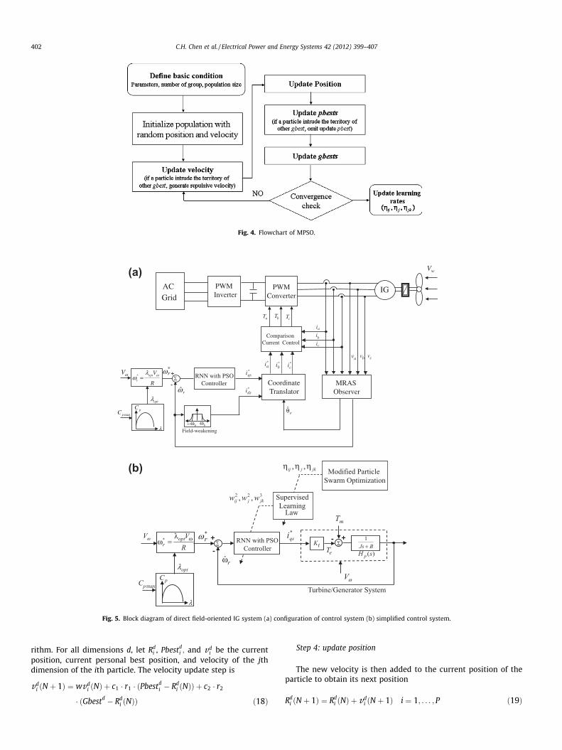
Fig. 4. Flowchart of MPSO.
∑+
-
Ta
ib
IGPWMInverter
ComparisonCurrent Control
CoordinateTranslator
RNN with PSO Controller
ωr* *
qsi
*ai
*bi
*ci
Tb Tc
av
eθ
*dsi
MRASObserver
ia
bv
ic
ACGrid
ω r
PWMConverter
R
Vopt
r
ωλω =*ωV
λ
pCmaxpC
optλ
Field-weakeningbωbω−
Vw
cv
(a)
(b)
Fig. 5. Block diagram of direct field-oriented IG system (a) configuration of control system (b) simplified control system.
402 C.H. Chen et al. / Electrical Power and Energy Systems 42 (2012) 399–407
rithm. For all dimensions d, let Rdi , Pbestd
i ; and vdi be the current
position, current personal best position, and velocity of the jthdimension of the ith particle. The velocity update step is
vdi ðN þ 1Þ ¼ wvd
i ðNÞ þ c1 � r1 � ðPbestdi � Rd
i ðNÞÞ þ c2 � r2
� ðGbestd � Rdi ðNÞÞ ð18Þ
Step 4: update position
The new velocity is then added to the current position of theparticle to obtain its next position
Rdi ðN þ 1Þ ¼ Rd
i ðNÞ þ vdi ðN þ 1Þ i ¼ 1; . . . ; P ð19Þ
Estimated rotor speed
Rotor speed reference and Actual rotor speed
Rotation speed error
Error=actual rotor speed-estimated rotor speed
Rotor speed reference and Actual rotor speed
Estimated rotor speed
Rotor speed reference
Actual and Estimated rotor speed
(a) (b)
(c) (d)
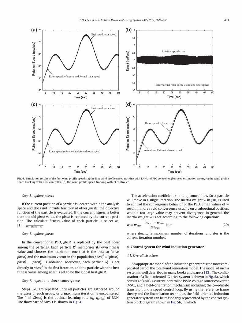
Fig. 6. Simulation results of the first wind profile speed: (a) the first wind profile speed tracking with RNN and PSO controller, (b) speed estimation errors, (c) the wind profilespeed tracking with RNN controller, (d) the wind profile speed tracking with PI controller.
C.H. Chen et al. / Electrical Power and Energy Systems 42 (2012) 399–407 403
Step 5: update pbests
If the current position of a particle is located within the analysisspace and does not intrude territory of other gbests, the objectivefunction of the particle is evaluated. If the current fitness is betterthan the old pbest value, the pbest is replaced by the current posi-tion. The calculate fitness value of each particle is select as:FIT ¼ 1
0:1þabsðxr�x�r Þ
Step 6: update gbests
In the conventional PSO, gbest is replaced by the best pbest
among the particles. Each particle Rdi memorises its own fitness
value and chooses the maximum one that is the best so far as
pbestdi and the maximum vector in the population pbestd
i ¼ ½pbestd1;
pbestd2; . . . pbestd
p� is obtained. Moreover, each particle Rdi is set
directly to pbestdi in the first iteration, and the particle with the best
fitness value among pbest is set to be the global best gbest.
Step 7: repeat and check convergence
Steps 3–6 are repeated until all particles are gathered aroundthe gbest of each group, or a maximum iteration is encountered.The final Gbestd
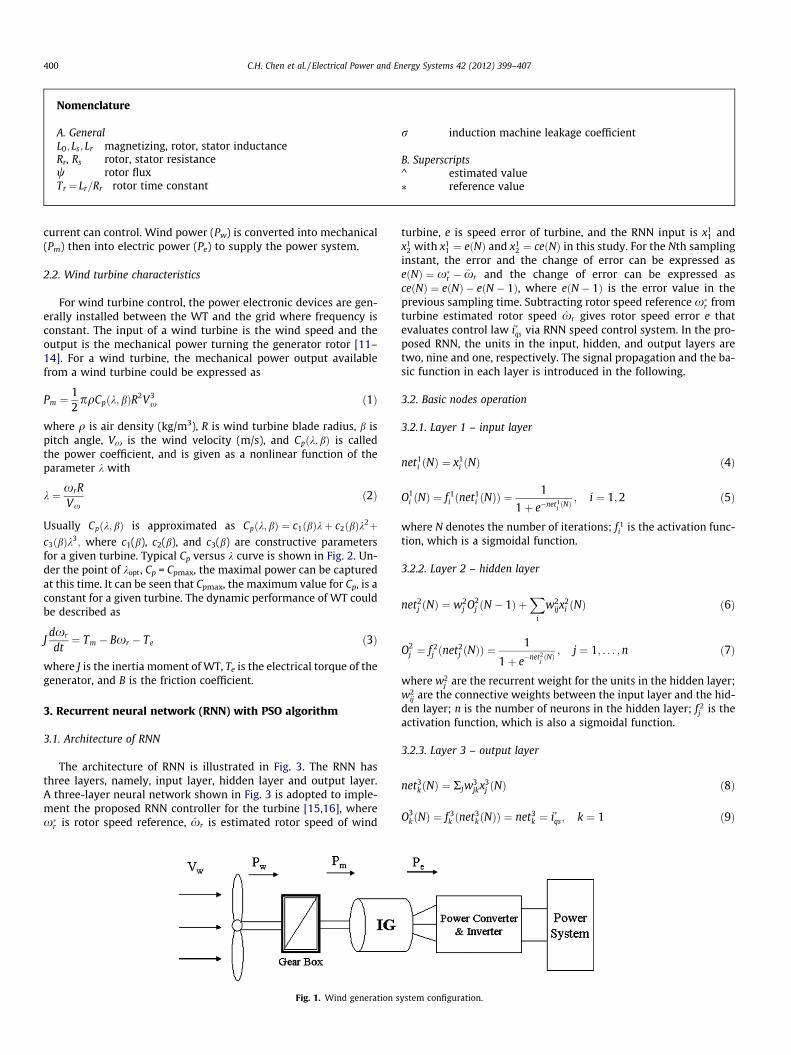
i is the optimal learning rate ðgij;gj;gjkÞ of RNN.The flowchart of MPSO is shown in Fig. 4.
The acceleration coefficient c1 and c2 control how far a particlewill move in a single iteration. The inertia weight w in (18) is usedto control the convergence behavior of the PSO. Small values of wresult in more rapid convergence usually on a suboptimal position,while a too large value may prevent divergence. In general, theinertia weight w is set according to the following equation:
w ¼ wmax �wmax �wmin
itermax� iter ð20Þ
where itermax is maximum number of iterations, and iter is thecurrent iteration number.
4. Control system for wind induction generator
4.1. Overall structure
An appropriate model of the induction generator is the most com-plicated part of the total wind generation model. The model of such asystem is well described in many books and papers [12]. The config-uration of a field-oriented IG drive system is shown in Fig. 5a, whichconsists of an IG, a current-controlled PWM voltage source converter(VSC), and a field-orientation mechanism including the coordinatetranslator, and a speed control loop. By using the reference frametheory and the linearization technique, the field-oriented inductiongenerator system can be reasonably represented by the control sys-tem block diagram shown in Fig. 5b, in which
Rotor speed reference
Actual and Estimated rotor speed
Rotation speed error
Error=actual rotor speed-estimated rotor speed
Rotor speed reference
Actual and Estimated rotor speed
Rotor speed reference
Actual and Estimated rotor speed
(a) (b)
(c) (d)
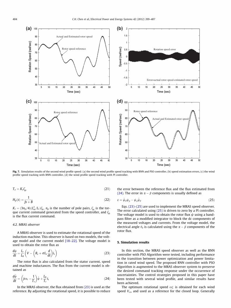
Fig. 7. Simulation results of the second wind profile speed: (a) the second wind profile speed tracking with RNN and PSO controller, (b) speed estimation errors, (c) the windprofile speed tracking with RNN controller, (d) the wind profile speed tracking with PI controller.
404 C.H. Chen et al. / Electrical Power and Energy Systems 42 (2012) 399–407
Te ¼ Kti�qs ð21Þ
HpðsÞ ¼1
Jsþ Bð22Þ
Kt ¼ ð3np=4ÞðL2m=LrÞi�ds; np is the number of pole pairs, i�qs is the tor-
que current command generated from the speed controller, and i�ds
is the flux current command.
4.2. MRAS observer
A MRAS observer is used to extimate the rotational speed of theinduction machine. This observer is based on two models, the volt-age model and the current model [18–22]. The voltage model isused to obtain the rotor flux as
dwdt¼ Lr
L0V � Rs þ rLs
ddt
� �is
� �ð23Þ
The rotor flux is also calculated from the stator current, speedand machine inductances. The flux from the current model is ob-tained as
dwdt¼ jxr �
1Tr
� �wþ L0
Tris ð24Þ
In the MRAS observer, the flux obtained from (23) is used as thereference. By adjusting the rotational speed, it is possible to reduce
the error between the reference flux and the flux estimated from(24). The error in a � b components is usually defined as
e ¼ wawb � wawb ð25Þ
Eqs. (23)–(25) are used to implement the MRAS speed observer.The error calculated using (25) is driven to zero by a PI controller.The voltage model is used to obtain the rotor flux w using a band-pass filter as a modified integrator to block the dc components ofthe measured voltages and currents. From the voltage model, theelectrical angle he is calculated using the a � b components of therotor flux.
5. Simulation results
In this section, the MRAS speed observer as well as the RNNcontroller with PSO Algorithm were tested, including performancein the transition between power optimization and power limita-tion in rated wind speed. The proposed RNN controller with PSOAlgorithm is augmented to the MRAS observer system to preservethe desired command tracking response under the occurrence ofuncertainties. The control strategies proposed in this paper havebeen tested with several wind profile, and similar results havebeen achieved.
The optimum rotational speed x�r is obtained for each windspeed Vx, and used as a reference for the closed loop. Generally
(a)
(b)
wP
mP
eP
Max. power reference
Generator Power
Turbine power
wP
mP
eP
Max. power reference
Generator Power
Turbine power
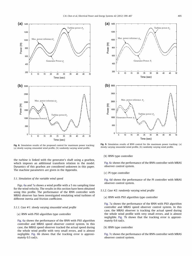
Fig. 9. Simulation results of RNN control for the maximum power tracking: (a)slowly varying sinusoidal wind profile, (b) randomly varying wind profile.
(a)
(b)
wP
mP
eP
Max. power reference
Generator Power
Turbine power
wP
mP
eP
Max. power reference
Generator Power
Turbine power
Fig. 8. Simulation results of the proposed control for maximum power tracking:(a) slowly varying sinusoidal wind profile, (b) randomly varying wind profile.
C.H. Chen et al. / Electrical Power and Energy Systems 42 (2012) 399–407 405
the turbine is linked with the generator’s shaft using a gearbox,which imposes an additional transform relation in the model.Dynamics of this gearbox are considered unknown in this paper.The machine parameters are given in the Appendix.
5.1. Simulation of the variable wind speed
Figs. 6a and 7a shows a wind profile with a 5 ms sampling timefor the wind velocity. The results in this section have been obtainedusing this profile. The performance of the RNN controller withMRAS observer has been investigated emulating wind turbines ofdifferent inertia and friction coefficient.
5.1.1. Case #1: slowly varying sinusoidal wind profile
(a) RNN with PSO algorithm type controller
Fig. 6a shows the performance of the RNN with PSO algorithmcontroller and MRAS speed observer control system. In thiscase, the MRAS speed observer tracked the actual speed duringthe whole wind profile with very small errors, and is almostnegligible. Fig. 6b shows that the tracking error is approxi-mately 0.5 rad/s.
(b) RNN type controller
Fig. 6c shows the performance of the RNN controller with MRASobserver control system.
(c) PI type controller
Fig. 6d shows the performance of the PI controller with MRASobserver control system.
5.1.2. Case #2: randomly varying wind profile
(a) RNN with PSO algorithm type controller
Fig. 7a shows the performance of the RNN with PSO algorithmcontroller and MRAS speed observer control system. In thiscase, the MRAS observer is tracking the actual speed duringthe whole wind profile with very small errors, and is almostnegligible. Fig. 7b shows that the tracking error is approxi-mately 0.6 rad/s.
(b) RNN type controller
Fig. 7c shows the performance of the RNN controller with MRASobserver control system.

(a)
(b)
wP
mP
eP
Max. power reference
Generator Power
Turbine power
wP
mP
eP
Max. power reference
Generator Power
Turbine power
Fig. 10. Simulation results of PI control for the maximum power tracking:(a) slowly varying sinusoidal wind profile, (b) randomly varying wind profile.
Table 1Performance for various control methods (slowly varying sinusoidal wind profile).
Averagepower
Max. speed trackingerror
RNN with PSO algorithmcontroller
814 W 0.5 rad/s
RNN controller 798 W 0.97 rad/sPI controller 768 W 1.3 rad/s
Table 2Performance for various control methods (randomly varying wind profile).
Average power Max. speedtracking error
RNN with PSO algorithm controller 1276 W 0.6 rad/sRNN controller 1256 W 1.37 rad/sPI controller 1221 W 5.0 rad/s
406 C.H. Chen et al. / Electrical Power and Energy Systems 42 (2012) 399–407
(c) PI type controller
Fig. 7d shows the performance of the PI controller with MRASobserver control system.
5.2. Simulation of the maximum power tracking
(a) RNN with PSO algorithm type controllerThe two wind speed profiles of maximum power tracking con-trol and the dynamic difference between the turbine power Pm
and generator power Pe due to the system inertia and frictionare also shown in Fig. 8a and b.
(b) RNN type controller
The two wind speed profiles verification of maximum powertracking control are shown in Fig. 9a and b.
(c) PI type controller
The two wind speed profiles verification of maximum powertracking control are shown in Fig. 10a and b.The simulation results show that the MRAS observer can track
the speed of the wind turbine with an error of less than 0.6 rad/sfor the whole speed range. Note that the actual speed is closelytracked by the estimation obtained from the MRAS. With the con-trolled rotor speed, the actual turbine power Pm and the generatorpower Pe can track the desired Pw closely. The system could capturethe maximal wind energy shown in the figures. It shows a robustcontrol performance of the proposed RNN with PSO algorithm con-troller and MRAS speed observer, both in the wind speed trackingand power regulation. Simulation results of performance for vari-ous control methods are shown in Tables 1 and 2.
6. Conclusion
This paper has presented a sensorless vector-control strategyfor an IG in a variable-speed WECS using a MRAS observer to esti-mate the rotational speed of the IG. Wind velocity sensorless oper-ation for wind power generation system have been presented inthis paper. We estimate the rotor position from flux linkages usingthe MRAS speed observer. MRAS based wind speed observer isdeveloped to provide fast and accurate velocity information toavoid using anemometers.
The dynamic performance can be used to obtain an accurateestimation of rotational speed not only in steady state but alsowhen fast input changes as wind steps are applied to the WECS.The approach used, based on a combination of RNN and a MRASspeed observer, allowed fast convergence to a simple linear dy-namic behavior, even in the presence of parameter changes andmodel uncertainties. However, the traditional PI controller cannotbe sure of the uncertainty model for various wind speed. The pro-posed MRAS speed observer and RNN with PSO Algorithm control-ler are successfully implemented in this study for the speed controlof WECS. This technique can maintain the system stability andreach the desired performance even with parameter uncertainties.
Appendix
The wind turbine generator system used for the simulation hasthe following parameters:
(1) wind turbine parameters:
Pm ¼ 1:5 KW; q ¼ 1:25 kg=m3; R ¼ 1:62 M; J ¼ 0:026244 Nm s2;B ¼ 0:007864 Nm s=rad.
(2) generator parameters:
Rs ¼ 1:1 X; Rr ¼ 1:3 X; Ls ¼ 0:1466 H; Lr ¼ 0:1466 H; Lm ¼ 0:136 H.
References
[1] Pena RS, Cardenas RJ, Asher GM, Clare JC. Vector controlled induction machinesfor stand-alone wind energy applications. Proc IEEE Ind Appl Annu Meeting2000;3:1409–15.
C.H. Chen et al. / Electrical Power and Energy Systems 42 (2012) 399–407 407
[2] Morimoto S, Nakayama H, Sanada M, Takeda Y. Sensorless outputmaximization control for variable-speed wind generation system usingIPMSG. IEEE Trans Ind Appl 2005;41(1):60–7.
[3] Lin FJ, Wai RJ, Lin PC. Robust speed sensorless induction motor drive. IEEETrans Aerosp Electron Systems 1999;35(2):532–42.
[4] Cardenas R, Pena R, Proboste J, Asher G, Clare J. MRAS observer for sensorlesscontrol of standalone doubly fed induction generators. IEEE Trans EnergyConvers 2005;20(4):710–8.
[5] Simoes MG, Bose BK, Spiegel RJ. Fuzzy logic-based intelligent control of avariable speed cage machine wind generation system. IEEE Trans PowerElectron 1997;12(1):87–95.
[6] Li H, Shi KL, McLaren PG. Neural-network-based sensorless maximum windenergy capture with compensated power coefficient. IEEE Trans. Ind Appl2005;41(6):548–1556.
[7] Tan K, Islam S. Optimum control strategies in energy conversion of PMSG windturbine system without mechanical sensors. IEEE Trans Energy Convers2004;19(2):392–9.
[8] Senjyu T, Tamaki S, Urasaki N, Uezato K, Higa H, Funabashi T, et al. Windvelocity and rotor position sensorless maximum power point tracking controlfor wind generation system. In: 35th Annual IEEE Power electron specialistsconf, 2004; 2023–2028.
[9] Mohamed MA, Hamdy A, Hamdy AE, Mohamed ES. Maximum power pointtracking using fuzzy logic control. Int J Electr Power Energy Syst 2012;39(1):21–8.
[10] Ghedamsi K, Aouzellag D. Improvement of the performances for wind energyconversions systems. Int J Electr Power Energy Syst 2010;32(9):936–45.
[11] Karrari M, Rosehart W, Malik OP. Comprehensive control strategy for avariable speed cage machine wind generation unit. IEEE Trans Energy Convers2005;20(2):415–23.
[12] Bose BK. Power electronics and AC drive. New York: John Wiley; 1986.[13] Ahmed MK, Ali MY. Robust control of an isolated hybrid wind–diesel power
system using linear quadratic gaussian approach. Int J Electr Power EnergySyst 2011;33(4):1092–100.
[14] Mohsen R, Mostafa P. Dynamic behavior analysis of doubly-fed inductiongenerator wind turbines – the influence of rotor and speed controllerparameters. Int J Electr Power Energy Syst 2010;32(5):464–77.
[15] Lu CH, Tsai CC. Adaptive predictive control with recurrent neural network forindustrial processes: an application to temperature control of a variable-frequency oil-cooling machine. IEEE Trans Ind Electron 2008;55(3):1366–75.
[16] Lin FJ, Lin CH, Hong CM. Robust control of linear synchronous motorservodrive using disturbance observer and recurrent neural networkcompensator. IEE Proc Electr Power Appl 2000;147(4):263–72.
[17] Esmin AA, Torres GL, Souza CZ. A hybrid particle swarm optimization appliedto loss power minimization. IEEE Trans Power Syst 2005;20(2):859–66.
[18] Schauder C. Adaptive speed identification for vector control of inductionmotors without rotational transducers. IEEE Trans Ind Appl 1992;28(5):1054–61.
[19] Tajima H, Hori Y. Speed sensorless field orientation control of the inductionmachine. IEEE Trans Ind Appl 1993;29(1):175–80.
[20] Yang G, Chin TH. Adaptive-speed identification scheme for a vector-controlledspeed sensorless inverter-induction motor drive. IEEE Trans Ind Appl1993;29(4):820–5.
[21] Peng FZ, Fufao T. Robust speed identification for speed-sensorless vectorcontrol of induction motors. IEEE Trans Ind Appl 1994;30(5):1234–40.
[22] Landau YD. Adaptive control – the model reference approach. MarcelDekker. New York: John Wiley; 1979.