Embed Size (px)
Citation preview

HUISHAN YU et al: INTELLIGENT STREET LAMP CONTROL SYSTEM USING ZIGBEE AND GPRS …
DOI 10.5013/IJSSST.a.17.35.36 36.1 ISSN: 1473-804x online, 1473-8031 print
Intelligent Street Lamp Control System using ZigBee and GPRS Technology
Huishan Yu1, Qun Sun2, Kai Sheng1, Zhenyou Wang2
1. School of Physics Science & Information Technology, Liaocheng University, Liaocheng 252059, China
2. School of Mechanical & Automotive Engineering, Liaocheng University, Liaocheng 252059, China Corresponding Author: Huishan Yu, [email protected]
Abstract - The traditional method of controlling street lamp lighting could not adjust the brightness of bulbs, while the management and maintenance had to rely on labour patrol. The combined ZigBee and GPRS technology with LED lights is an advanced controlling method for street lighting, particularly resolves the issues in monitoring and energy consumption. This paper presents a general system that incorporates a street lighting-control center, supervision sub-stations and lighting control terminals. ZigBee and GPRS wireless communication technologies formed the bridge of the general system, and helped achieve remote control of street lighting, monitoring and fault warning. Keywords: ZigBee technology; GPRS technology; street lighting-control system; CC2530, LED lamp
I. INTRODUCTION The system of Traditional Street Lamp (TSL) could not
remotely recognize faulty lights and control brightness and switching, leading to rise of operational and maintenance costs. The intelligent street lamp control system (ISLCS) could save the human and material resources, improve service efficiency, and reduce maintenance costs by remote control of Ad Hoc Networks, comparing with TSL [1].
In China, intelligent street lamp (ISL) systems have vast market demands and high profits, and gradually take major competitive positions in almost all street lamp producers. For example, Tiantuo Group produced a large amount of LED ISL systems for urban and tunnel lighting. The LED lamps are monitored in real time based on G-Bus system, and the LED lamps can adjust the circuit voltage and current, saving 20%-40% of energy. At the same time, Chinese Academy of sciences cooperated with American Sensity company and researched in intelligent street lamp systems as well as smart city facilities.
In developed countries, intelligent street lamp is not only a tool of lighting, but also the base of smart city. Philips and Ericsson companies launched 4G LED ISL, which provides seamless 4G LTE service in daytime and works as street lamp during night. The rate of power saving reached 60% and the range of Internet connections has been expanded. American Sensity company is developing a global Netsense platform and planning to promote
associated applications. The staffs of Sensity company collect data from embedded sensors in the lamps and transfer through wireless connection and carry out information analysis. Besides cloud applications and service have also been started. French Streetlight Vision and British Tlelnsa Company are also developing ISLCS [2-4]. All the above events mean that smart city development based on intelligent street has been started.
This paper mainly represents studies on whole design of Street Lamp Management Center (SLMC), Monitor Substation (MS), Street Lamp Control Terminal (SLCT), based on CC2530 of ZigBee and General Packet Radio Service (GPRS). It also includes researches in wireless network and hardware circuit of ISLCS and design of system software. Based on the above, remote control and monitoring have been achieved.
II. INTEGRATED DESIGN OF INTELLIGENT STREET
LAMP CONTROL SYSTEM A. Whole Structure of the System
According to application requirement and typical
structure of remote control system (monitor center, communication module and terminal control unit), a three-level network structure has been developed including street lamp management center, monitoring substation and street lamp control terminal, as showed in Figure 1.

HUISHAN YU et al: INTELLIGENT STREET LAMP CONTROL SYSTEM USING ZIGBEE AND GPRS …
DOI 10.5013/IJSSST.a.17.35.36 36.2 ISSN: 1473-804x online, 1473-8031 print
GPRS Modular
Street Lamp management
Center
GPRS Network
Monitor Substation
Street Lamp Contrlo Terminal
ZigBee Network ZigBee Network ZigBee Network
Line 1 Line 2 Line N Figure1 Whole structure diagram of network ISLCS.
1. Street Lamp Management Center (SLMC) SLMC monitors overall street lamp control system
through PC software and manages all street lamps. 2. Monitor Substation (MS) MS forwards control data to street lamp control terminal
through ZigBee network when it accepts operational commands that came from SLMC. It could also maintain mode information of SLCT, and fed back node data to SLMC by GPRS networks.
3. Street Lamp Control Terminal (SLCT) SLCT could accept orders of MS, and carry out the
order.
1.1. Operating Principle of the System TSLCS needs to configure the on/off status of street
lamps and control degree of brightness according to day light intensity, weather and traffic at night. When the lamps in the system fail, SLMC could receive the status and remotely control the city street lamps accordingly [5].
Data transmission was based on remote GPRS communication mode and short-range ZigBee communication mode in ISLCS. GPRS network realize communication between MS and SLCT. Flow chart of communication is shown in Figure 2.
Figure2 Flow chart of communication of ISLCS.
The on/off status and brightness of ISLCS were combinations of optical and time control approaches. In daytime, when the weather becomes bad, light intensity was lower than the pre-set value, and then the lights are switched on automatically. When light intensity became normal, the lights are closed. At night, when peak flow of traffic occurs, the street lamps give 100% output. After peak traffic flow, the street lamps remain 50% output, until some vehicle or people pass street lamp.
III. RESEARCH OF WIRELESS NETWORK OF ISLCS
A. Choosing of Short-Rang Wireless Communication Technology
Wi-Fi, Bluetooth, UWB, NFC and ZigBee are
commonly used short-range wireless communication technologies as shown in Table 1.

HUISHAN YU et al: INTELLIGENT STREET LAMP CONTROL SYSTEM USING ZIGBEE AND GPRS …
DOI 10.5013/IJSSST.a.17.35.36 36.3 ISSN: 1473-804x online, 1473-8031 print
TABLE1 COMPARISON OF SHORT-RANGE WIRELESS COMMUNICATION
Name ZigBee Wi-Fi Bluetooth UWB NFC
Transmission speed 100Kbps 11-54Mbps 1Mbps 53-480Mbps 424K
Transmission distance 20m-100m 20-200m 10m 0.2-40m 20cm
Band 2.4GHz 2.4GHz 2.4GHz 3.1GHz 13.56Hz
Safety Medium Low High High High
Power Cost Low High Low High Low
Application Wireless Sensor Wireless Online, PC, PDA Vehicle, Multimedia Wireless HD Mobile
The above several short-range wireless communication
technologies have different characteristics, suitable for different applications. The real-time and stability requirements of intelligent lighting control system can be met by ZigBee equipment, with its other advantages such as low cost, flexibility, high safety, small volume, and low power consumption, thus using ZigBee technology [6] is most suitable for this intelligent lighting control system.
B. ZigBee Network Device Type
ZigBee network according to equipment functions can
be divided into Full Function Device (FFD) and Reduced Function Device (RFD). In ZigBee network, FFD implements all of the ZigBee protocols, thus FFD can communicate with the FFD and RFD. Whilst RFD only implements a part of the IEEE 802.15.4 protocol thus can only communicate with FFD. The network that is classified according to role in network is divided into Coordinator, Router and Terminal. ZigBee function and device type are shown in Table 2.
TABLE 2. ZIGBEE DEVICE TYPE
Device Type Function
Coordinator FFD Hoc network, Assign the network
addresses, Maintain the routing table
Router FFD Expand network physical area and node
that join in network
Terminal RFD Monitor/Control function
In the Intelligent Street Lamp Control System, MS are
as Coordinator of ZigBee network and SLCT are as Router of ZigBee network. The whole network is controlled by Coordinator of MS which sets up network and configures data. The role of SLCT is a relay controller of the system which transmits signal and controls street lamp.
C. Design of the Network Scheme of ZigBee
ZigBee network should be firstly built by MS
Coordinator. Then, Coordinator of SLCT or ZigBee Terminal Device took part in the network. ZigBee communication is built between MS and SLCT.
C1. Establishing Network by MS Coordinator
A ZigBee network is built by MS Coordinator and the flowchart is shown in Figure 3.
Figure 3. Flowchart of Router building network
Several requirements should be satisfied:
(1) The node must be FFD node; (2) No other network is connected by node. The creation process of node by Coordinator is: (1) Confirming Coordinator; (2) Scanning channel; (3) Setting ID number of network.
When the network layer finishes scanning channel,
choosing PAN ID, and deciding 16-digit network address, a MLME-START request is sent to the MAC layer to create new network. Request language will be sent to network layer. MLME. START. Confirm and NLME.NETWORK.FORMATION. Confirm instructions retrieve the results of newly established network.

HUISHAN YU et al: INTELLIGENT STREET LAMP CONTROL SYSTEM USING ZIGBEE AND GPRS …
DOI 10.5013/IJSSST.a.17.35.36 36.4 ISSN: 1473-804x online, 1473-8031 print
C2. Adding Route Nodes to Network When creating network is successful, ZigBee Router or
Terminal is added to the network through Coordinator. The flowchart is shown in Figure 4.
Figure 4. Flowchart of adding route nodes to network
The network topological structure was used in ISLCS. When a node has trouble, other nodes will replace the node. This structure protects the system network [9]. C3. GPRS System Network Technology
GPRS technology is used in remote communication in this system [11, 12]. The advantages of GPRS technology are low cost, high transmission efficiency, wide scope and fast connection.
The network creation scheme depends on the accessing methods of SLMC, and the influential factors of choosing the network scheme are safety, cost and data. Transmission mode of public network with fixed IP address is used, after consideration of the system development cost and the following maintenance convenience.
The GPRS network of MS and SLMC create Socket connections. The GPRS network of MS is the client of Socket, and SLMC is the server of Socket [13]. The Socket connection is divided into TCP protocol and UDP protocol [19]. Data transmission method of TCP is safe but slow, and UDP protocol is contrary. Thus TCP protocol is fit in ISLCS.
IV. DESIGN OF HARDWARE A. Overall Design of ISLCS Hardware
Hardware structure of ISLCS mainly consists of two
parts: SLCT hardware and ZigBee MS Coordinator gateway. The functions of SLCT are to collect information, transmit data and execute commands that come from SLML. ZigBee wireless network transmits data and CC2530 of wireless microcontroller collects information. The Coordinator is a device of transmitting information and provides data exchange between SLMC and SLCT. The whole structure is shown in Figure 5.
Figure 5. Whole structure of system hardware
B. Design of SLCT Hardware
SLCT is made up of ZigBee communication module, processor module, current and voltage detection circuit,
radar detection circuit and LED dimming control circuit. ZigBee module is wireless transceiver. The hardware structure diagram is shown in Figure6.

HUISHAN YU et al: INTELLIGENT STREET LAMP CONTROL SYSTEM USING ZIGBEE AND GPRS …
DOI 10.5013/IJSSST.a.17.35.36 36.5 ISSN: 1473-804x online, 1473-8031 print
Figure 6. Hardware diagram of SLCT
The functions of SLCT are: (1) control the street lamp
switching; (2) At night, adjust lamps lightness through radar signal; (3) when the lamps faults occur, feed the errors back to SLMC. B1. Design of LED Dimming Control Circuit
LED lamps were chosen for the advantages in safety, environment, energy-efficiency, long life span, easy brightness adjustment and so on.
LED lamps generally use the dimmer way of PWM to adjust brightness. The PWM outputs are pulse width signals with variable duty ratios, and different duty ratios correspond to different mean current and hence different brightness [14].
LED lamps need a constant current power supply to drive the circuit. LED driver is a switching power supply with constant current and steady voltage. LM3409HV chip was chosen as the driver for its wide range of input voltage. According to the PWM waves the current was allowed or
forbidden to flow through the LED, and adjusting PWM duty ratio changes the average time the current flows through the LED, thus controls the brightness.
B2. Design of Illumination Detection Circuit
LED lamps switching in this design are automatically controlled by light intensity. When the luminous flux densities of light attain 50lx, the lamps will open. When the luminous flux densities of light attain 100lx, the lamps will close.
The illumination detection circuit is composed of light intensity sensor and current to voltage conversion circuit. The light range measurable by the sensor is from 0lx to 200lx and corresponds to current from 4mA to 20mA. The current signals are converted into voltages from 0V to 5V by current-voltage conversion circuit. The voltage signals are changed from 0-5V to 0-3.3V and then go to the CC2530 microcontroller. The current to voltage conversion circuit is shown in Figure 7.
Figure 7. Current/Voltage conversion circuit schematic.

HUISHAN YU et al: INTELLIGENT STREET LAMP CONTROL SYSTEM USING ZIGBEE AND GPRS …
DOI 10.5013/IJSSST.a.17.35.36 36.6 ISSN: 1473-804x online, 1473-8031 print
B3. Design of Current/Voltage Detection Circuit The function of circuit detection is to monitor the status
of lamps. When circuit is open or shorted, the voltage that is collected by detection circuit will become 0V. The stoppage is shown in street lamp management center.
In the voltage input terminal, equivalent input impedance is above 1MΩ sample voltage. Then, input voltage is attenuated 15times. The voltage arrives in AD input terminal through voltage detection circuit, as shown in Figure 8.
Figure 8. Voltage detection circuit.
Current signals are converted into voltage signals by a
current detection circuit. The function of differential operational amplifier is recognizing direction of current
flow. Then, the current feeds in current detection circuit, and voltage (0-3V) is sent out. At last, the voltage arrives in ADIN terminal. The circuit is shown in Figure 9.
Figure 9. Current detection circuit.
B4. Design of Radar Detection Circuit
After 23 o’clock, lighting level is controlled by radar detection circuit. The street lamps normally keep a state of 50% output. When some vehicles or people pass street lamps, street lamps return to a state of 100% output.
This circuit detects moving objects by 24GHz
microwave Doppler radar detector. The detector can detect speed of moving objects by measuring reflected wave.
The radar is mounted at crossings and the distance of two radars is 200m. When radar detects vehicles, street lamps in front of the radar will be switched on. The circuit is shown in Figure 10.

HUISHAN YU et al: INTELLIGENT STREET LAMP CONTROL SYSTEM USING ZIGBEE AND GPRS …
DOI 10.5013/IJSSST.a.17.35.36 36.7 ISSN: 1473-804x online, 1473-8031 print
Figure 10. Radar detection circuit.
C. Design of MS Hardware
MS is the coordinator of ZigBee. It is connected with
SLMC by GPRS network and SLCT by ZigBee. The coordinators integrate data from sensor node of SLCT. Then the data will be uploaded to SLMC by GPRS.
The hardware includes GPRS module, ZigBee-GPRS gateway and gateway power. The main function of ZigBee-GPRS gateway is to convert and transmit data of ZigBee to GPRS network.
C1. Choosing of GPRS Module
SIM900A produced by SIMCOM Company is used. The advantages of the module are safety, low cost and tight configuration.
C2. Design of ZigBee-GPRS Gateway
GPRS terminal can convert data to RS232 type [16], thus a serial port circuit should be designed. The structure
of gateway is shown in Figure 11.
Feed circuit GPRS Terminal
ZigBeeModule
Serial Port
Circuit
TXD
RXD
GXD
TXD
RXD
GXD
Figure 11. Structure of gateway.
SIM900A is connected with CC2530 by serial port.
TXD is data sending pin of the serial interface. RXD is data receiving pin of serial interface. GND is ground strap. SIM900A is controlled by AT order sent by CC2530.
ZigBee gateway is supplied power by adapter. It needs two type voltages (3.3V to ZigBee module and 4.2V to GPRS module). The power circuit is shown in Figure 12.
Figure 12. Power circuit.
HUISHAN YU et al: INTELLIGENT STREET LAMP CONTROL SYSTEM USING ZIGBEE AND GPRS …
DOI 10.5013/IJSSST.a.17.35.36 36.8 ISSN: 1473-804x online, 1473-8031 print
V. DESIGN OF SYSTEM SOFTWARE
This research uses layer and modular design in the system software [16].
A. The Software Design of SLCT
The street lamps control terminal uses hardware circuit to collect status data of street lamps and transmit the data to MS coordinator by ZigBee wireless communication. It can also execute order of the coordinator. After electrifying, initialization of hardware device and protocol stack start, and then channel scanning is stated. The scan took place in wireless network that was established by the coordinator. After the previous step, data of street lamps collection will start and the data will be sent to coordinator. Data collection flowchart is shown in Figure13.
There are different lighting schemes provided: (1) From 6 to 18 o’clock, street lamp is closed, until
weather becomes bad. (2) From 18 to 23 o’clock, there is a peak flow of
traffic. So, the state of street lamps should be kept to 100% output.
(3) From 23 to 6 o’clock, the rush hour is over. The street lamps keep a state of 50% output, until some vehicles or people pass the street lamps.
The main-program flow diagram of SLCT is shown in Figure 14.
Figure 13. Data collection of SLCT flowchart.

HUISHAN YU et al: INTELLIGENT STREET LAMP CONTROL SYSTEM USING ZIGBEE AND GPRS …
DOI 10.5013/IJSSST.a.17.35.36 36.9 ISSN: 1473-804x online, 1473-8031 print
Figure 14. Main-program flow diagram of SLCT.
B. Design of MS Software
In ISLCS, MS connects SLMC and SLCT by GPRS
network and ZigBee network. The ZigBee network was built by coordinator. When creating network success, coordinator or Terminal Router is added to the network. The
network addresses were assigned. The node data is integrated and will be uploaded to the host computer. When a host computer order is sent to MS, the order is sent to a target node [18]. The main-program flow diagram of MS is shown in Figure 15.

HUISHAN YU et al: INTELLIGENT STREET LAMP CONTROL SYSTEM USING ZIGBEE AND GPRS …
DOI 10.5013/IJSSST.a.17.35.36 36.10 ISSN: 1473-804x online, 1473-8031 print
Figure 15. Main-program flow diagram of MS.
C. Software Design of SLMC
The functions of SLMC software are to build user interface and make human-machine exchanges. The software sends SLCT data collected by MS to host computer of SLMC. At the same time, the software remotely monitors street lamps.
C1. Function Design of SLMC
The functions of SLMC software are to display state of street lamps in real-time, voice alarm, purview management, convenient control, friendly interface, and so on.
C2. Interface Design of SLMC
The operating interface was written by Visual Studio [18].
(1) Login interface The login interface is password protected and classified
by management levels. This can improve the system safety factor. The login interface is shown in Figure 16.
Figure 16. Login interface.

HUISHAN YU et al: INTELLIGENT STREET LAMP CONTROL SYSTEM USING ZIGBEE AND GPRS …
DOI 10.5013/IJSSST.a.17.35.36 36.11 ISSN: 1473-804x online, 1473-8031 print
(2) Main-control interface Staff can control street lamps and view data in
main-control interface. This interface includes street lamp control interface and data examining interface. Street lamps state, lighting and alarm state are shown in street lamp control interface. The main function of data examining interface is real-time display of current, voltage and power. The main-control interface is shown in Figure 17.
a) Street lamp control interface
b) Data examining interface
Figure 17. Main-control interface.
C3. Serial Port Communication Design of SLMC Serial port of SLMC Computer is RS232 level. Serial
port of MS GPRS DTU Module is TTL level. So, a level-conversion circuit based on MAX232 is required.
C4. Communication Design Between SLMC and MS
GPRS module of MS and SLMC is connected with Socket. Socket’s main functions are network communication programming and dealing with intricate data. Communication flow can divide three steps: server listen, client request and confirm the connection [19]. The
flow diagram is shown in Figure 16.
Figure18 Communication flow diagram
VI. EXPERIMENT
This design has been finished and experiments carried
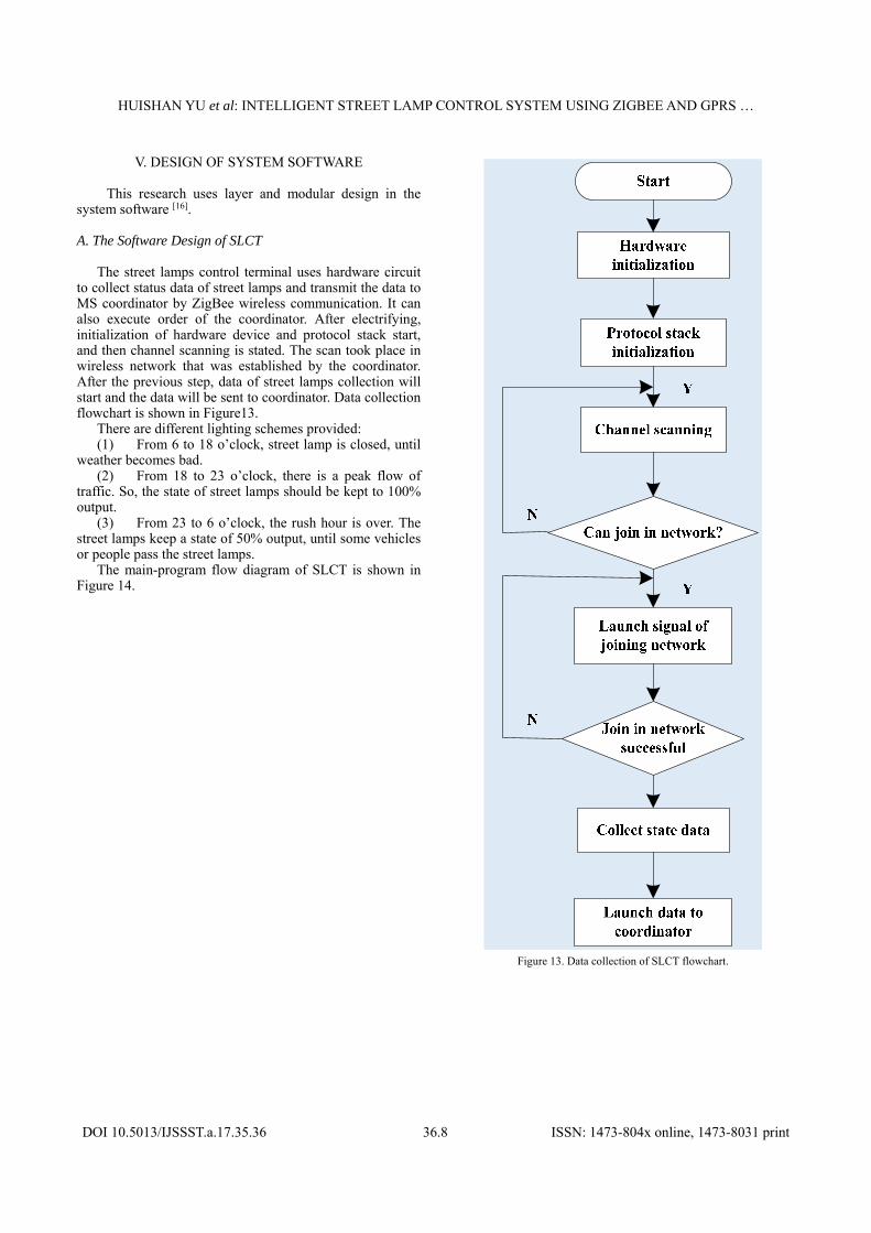
out in a laboratory with objects of different people. The street lamp control system consists of five simulated lamps, independent switch and slider of adjusting brightness. Experimental variables are people and light intensity. Malfunction and alarm can be checked in main-control interface. Viewing data interface real-time displays current, voltage and power of the street lamps. Functionalities of this design are tested many times by a variety of people and lighting. The mimic models are shown in Figure 19 (a) to (d). Street lamps voltage is shown in Figure (e).
HUISHAN YU et al: INTELLIGENT STREET LAMP CONTROL SYSTEM USING ZIGBEE AND GPRS …
DOI 10.5013/IJSSST.a.17.35.36 36.12 ISSN: 1473-804x online, 1473-8031 print
(a)Whole simulated diagram in laboratory (b) Night mode
(c) Physical map of MS (d) Light-intensity detection
(e) Street lamps voltage diagram collected by SLMC
Figure 19. Simulation diagram
The experimental results of the analysis meet the design
basic requirements. But there are several aspects that need to be improved. (1) Formal tests should be accomplished outdoors; (2) street lamp nodes and vehicles should be increased; (3) sensitivity of radar and dimming control circuit should be adjusted more properly; (4) stability and reliability of hardware circuit should be improved.
VII. CONCLUSION
This study presents a design of intelligent lighting control system based on the ZigBee technology and the combination of GPRS technology to overcome shortcomings of traditional street lamps. In terms of the lighting control aspects, the system combines time control, light intensity control, pedestrian occurrence control, upper PC control and other methods, to provide enhanced flexibility and humanized lighting. Meantime the system increases information collections of the lamp voltage, lamp current and light intensity, carries out analysis of the working status of street light in the host computer. This
provides an important basis for troubleshooting and maintenance, and enhances the timeliness of real-time management of street lamps. The street lamp coverage meets city requirements at the same time, with a much reduced number of GPRS modules, effectively reduces the cost of the system. Under the premise of ensuring scientific lighting, the system effectively saves power resource and improves the management efficiency.
REFERENCES [1] Yude Dong, Changhao Zhang, et al. Design of GIS- Based digital
lighting system for city road. Journal of South China University of Technology (Natural Science Edition). 2016, 44(1):50-57. ( in Chinses)
[2] Y M Jagadees, S Akilesh, et al. Intelligent street lingts. ScienceDirect. 2015. 21(8): 547-551.
[3] Min He. The research and application of distributed digital LED lighting controller. Guang Zhou: South China University of Technology. 2012. (in Chinses)
[4] Rodrigo Pantoni, Dennis Brandao. A confirmation-based geocast routing algorithm for street lighting systems. Computers & Electrical

HUISHAN YU et al: INTELLIGENT STREET LAMP CONTROL SYSTEM USING ZIGBEE AND GPRS …
DOI 10.5013/IJSSST.a.17.35.36 36.13 ISSN: 1473-804x online, 1473-8031 print
Engineering. 2011. 37(6): 1147-1159. [5] Tao Ji, Fengming Wu, et al. On the intelligent street light control
based on multi-level luminance. Journal of Huzhou Teachers College. 2012, 34(1):32-36. (in Chinses)
[6] Margaret Carol Beel, Fabio Galatioto. Novel wireless pervasive sensor network to improve the understanding of noise in street canyons. Applied Acoustics. 2013, 74(1): 169-180.
[7] Ortiz Antonio M, RoyoFernando, et al. On reactive routing protocols in ZigBee wireless sensor networks.Expert Systems. 2014, Vol. 31(5): 154-162.
[8] Hui Li, Lingying Zhao, Ling Peter, Jia Liu. A model for predicting wireless signal transmission performance of ZigBee-based sensor networks in residential houses. Ashrae Transactions.2012, 118: 994-1007.
[9] Boris Snajder, VanaJelici, et al. Wireless sensor node modelling for energy efficiency analysis in data-intensive periodic monitoring. Ad Hoc Networks. 2016. 49(10): 29-41.
[10] Dongdong Wang, Wencheng Guo, et al. Design of wireless street lamp control system based on ZigBee. Journal of Tianjin Polytechnic University. 2009, 28(1): 84-88. (in Chinses)
[11] Andrew JWilson.The use ofGPRStechnology for electricity network telecontrol. Computing & Control Engineering.2005,16(4): 40-45.
[12] Raul Ionel, Laura Pitulice, Gabriel Vasiu, Septimiu Mischie, Otilia Bizerea Spiridon. Implementation of a GPRS based remote water quality analysis instrumentation. Original Research Article Measurement. 2015, 65(4): 81-93.
[13] Ziwei Zheng. Application of Web Socket in real-time communication. Journal of Xiamen City Vocational College. 2015, 3(9): 47-51. (in Chinses)
[14] Gil-de-Castro A, Moreno-Munoz A,et al.LEDstreetlighting: A power quality comparison amongstreetlighttechnologies. Lighting Research & Technology.2013, 45(12): 710-728.
[15] M. Baadeche, F. Soltani Performance analysis of ordered CFAR detectors for MIMO radars.Digital Signal Processing. 2015, 44(9): 47-57.
[16] Di Xu. Research and realization of wireless monitoring gateway based on GPRS. Nanjing University of Posts and Telecommunications. 2012. (in Chinses)
[17] Timilehin Labeodana, Christel De Bakkerb, Alexander Rosemannb, Wim Zeilera. On the application of wireless sensors and actuators network in existing buildings for occupancy detection and occupancy-driven lighting control. 2016, 127(1): 75-83.
[18] Jihong Jin, Shuzhi Liu. Research and realization of network communication software based on TCP protocol. Journal of Jiaozuo Teachers College. 2015, 31(6): 67-70.
[19] A. Singaravelan, M. Kowsalya. Design and Implementation of Standby Power Saving Smart Socket with Wireless Sensor Network. Procedia Computer Science. 2016, 92(7): 305-310.


![ZigBee Stack Profile: Platform restrictions for compliant ...read.pudn.com/.../3...ZigBee-Feature-Set-Profile.pdf · 11 [R2] ZigBee 04140r05, ZigBee Protocol Stack Settable Values](https://img.pdfslide.net/doc/110x75/5f183a7d6417c0751a61665e/zigbee-stack-profile-platform-restrictions-for-compliant-readpudncom3zigbee-feature-set-.jpg)


![ZigBee RF4CE Stack User Guide - NXP Semiconductors · 094945r00ZB ZigBee RF4CE Specification [ZigBee Alliance document] 094950r00ZB ZigBee RF4CE Device Type List [ZigBee Alliance](https://img.pdfslide.net/doc/110x75/5f168d2f412bb13bb1076764/zigbee-rf4ce-stack-user-guide-nxp-semiconductors-094945r00zb-zigbee-rf4ce-specification.jpg)