Embed Size (px)
Citation preview

Intellis
AS-i Network MonitorModel 7704, 7744 & 7779
Installation and Operation Manual

D.W.O. 16500 Tech-316
Revision History
Revision 1.0 4 April 2002Initial Version
Revision 1.122 November 2004Document was updated to reflect new PCB design, addition of pneumatic section, misc. correc-tions and changes in IOM format.
D.W.O. 16500 Tech-316
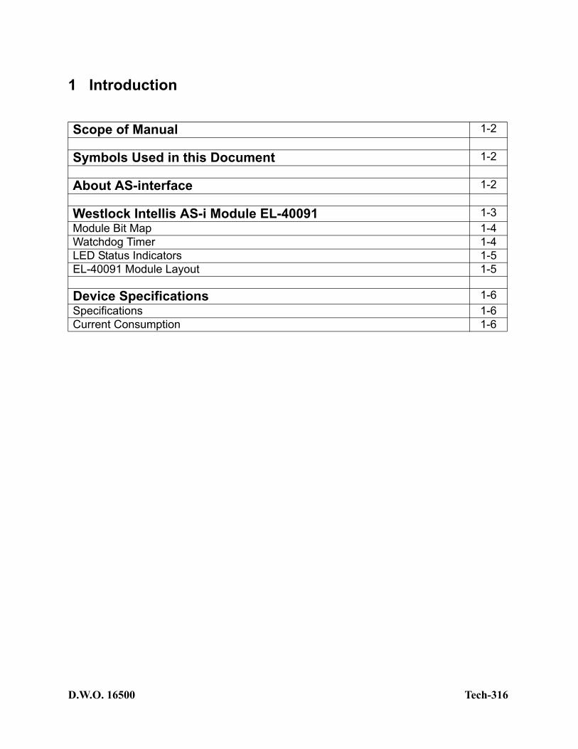
1 Introduction
Scope of Manual 1-2
Symbols Used in this Document 1-2
About AS-interface 1-2
Westlock Intellis AS-i Module EL-40091 1-3Module Bit Map 1-4Watchdog Timer 1-4LED Status Indicators 1-5EL-40091 Module Layout 1-5
Device Specifications 1-6Specifications 1-6Current Consumption 1-6

D.W.O. 16500 1- Tech-316
1.1 Scope of Manual
This manual contains installation, configuration and specification data for the AS-iPAC AS-i valve controller.This manual assumes a basic level of familiarity and competence with AS-i terminology and tech-nology. Only qualified personnel should install, operate and maintain this equipment.
1.2 Symbols Used in this Document
This symbol warns the user of possible danger. Failure to heed this warning may lead to personal injury or death and/or severe damage to equipment.
This symbol identifies information about operating the equipment in a particular manner that may damage it or result in a system failure. Failure to heed this warning can lead to total failure of the equipment or any other connected equipment.
This symbol draws attention to information that is essential for understanding the opera-tion and/or features of the equipment.
1.3 About AS-interface
AS-i is an easy to use, low-cost, network solution that has been designed specifically for use in low level automation systems. AS-i is a digital replacement for traditional parallel wiring that is easy to install, simple to configure, operate and maintain. AS-i technology is highly flexible in its topology and is compatible with many fieldbus or device networks. Low-cost gateways exist to use AS-i with Modbus, Modbus +, DeviceNet, PROFIBUS, Ethernet, Interbus, FIP, LON, RS-485,RS-422 and RS232.AS-International, the sponsor organization of AS-i, was formed in 1991 by a consortium of 11 European companies who developed the standard. Today, this association is open to any manufac-turer or user of this technology and boasts a membership of nearly 100 companies worldwide,
2

D.W.O. 16500 1- Tech-316
offering over 600 products and services. The North American Chapter, the AS-i Trade Organiza-tion (ATO), was formed in April of 1996. Through the ATO, members can submit AS-i products for conformance testing and certification.Westlock Controls is a member of the ATO and our AS-I products are conformance tested and certified.
1.4 Westlock Intellis AS-i 2.1 Module EL-40091
The AS-i Pneumatic Actuator Controller (APAC) EL-40091 module is a four input, two output network monitor with default slave profile S-7/A, (S-I/O code/ID code). Inputs 0 and 1 are internal Hall Effect sensors that are activated by the shaft trigger assembly magnets (South Pole). Inputs 2 and 3 are active low (activated by pulling the input to ground) for use with dry contact type sensors. Outputs are FET (field effect transistor) open drain active low with diode and short circuit protection.The module consumes 45 mA of current with both inputs and one output active driving a standard NI Falcon solenoid (20mA non-incendive solenoid coil). Minimum power supply input voltage is 19 Vdc to assure proper communications.Connection to the network is via the single unshielded two-wire cable that supplies power, nomi-nal 30 Vdc, and signal. The sensors and actuator are connected to the AS-i cable via the AS-i slave chip.In the Extended Address Mode 62 slaves can be used on one network. The address range is still 1-31 but each slave is assigned as an “A” slave or a “B” slave. The fourth output data bit of the slave is used to identify whether a slave is an “A” slave or a “B” slave.In each scan cycle, 3 output data bits plus one address selector bit (“A” slave or “B” slave indica-tion) are transferred serially to each slave from the master and 4 input data bits are returned to master by each slave. In a full configuration with 62 slaves the scan cycle time is 10 ms. For a net-work with 31 slaves the scan cycle time is 5 ms. Scanning is deterministic.For data exchange to occur, each network monitor connected to the AS-i network must be pro-grammed with an unique address, numbered between 1-31 “A” and 1-31 “B” for Extended Address Mode. This may be accomplished via a handheld programmer or directly through the master. The address, which can be changed at any time, is stored internally in an EEPROM.
Note: To utilize the extended addressing mode an AS-i Specification rev.2.1 master must be used.
3

D.W.O. 16500 1- Tech-316
1.4.1 Module Bit Map
1.4.2 Watchdog Timer
The AS-i processor has an embedded watchdog timer that is enabled in the EL-40091 Module. The watchdog timer will be activated for any slave address after the reception of a Write_Parameter Request. It will be de-activated by any circuit reset and after the reception of a Delete_Address Request.When activated, the watchdog timer will be reset by every Write_Parameter and Data_Exchange Request received by the slave. If no such request is receive by the slave within 40 ms, a hardware reset will be performed by the slave and Outputs will be switched inactive de-energizing any attached solenoids.
Table 1I/O TYPE MODULE REFERENCE BITMAP OF DATAInput 0 Active High/Low1 Closed, Bottom Limit Sensor Byte 0, Bit 0Input 1 Active High/Low1 Open, Upper Limit Sensor Byte 0, Bit 1Input 2 Active High/Low1 Auxiliary Input 1 Byte 0, Bit 2Input 3 Active High/Low1 Auxiliary Input 2 Byte 0, Bit 3Output 0 Active Low2 OUT_0 to Solenoid A Byte 0, Bit 0Output 1 Active Low2 OUT_1 to Solenoid B or Aux-
iliary OutputByte 0, Bit 1
1 Active High indicates that pulling the input pin up to V+ activates the input. Active Low indicates that pulling the input pin down to ground activates the input.2 Active Low indicates that the output is an open collector type circuit.
4
D.W.O. 16500 1- Tech-316
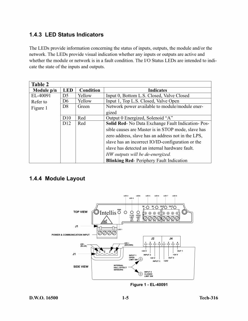
1.4.3 LED Status Indicators
The LEDs provide information concerning the status of inputs, outputs, the module and/or the network. The LEDs provide visual indication whether any inputs or outputs are active and whether the module or network is in a fault condition. The I/O Status LEDs are intended to indi-cate the state of the inputs and outputs.
1.4.4 Module Layout
Table 2Module p/n LED Condition Indicates
EL-40091Refer to Figure 1
D5 Yellow Input 0, Bottom L.S. Closed, Valve ClosedD6 Yellow Input 1, Top L.S. Closed, Valve OpenD8 Green Network power available to module/module ener-
gizedD10 Red Output 0 Energized, Solenoid “A”D12 Red Solid Red- No Data Exchange Fault Indication- Pos-
sible causes are Master is in STOP mode, slave has zero address, slave has an address not in the LPS, slave has an incorrect IO/ID-configuration or the slave has detected an internal hardware fault.HW outputs will be de-energized.Blinking Red- Periphery Fault Indication
5
IN2
IN3
OUT0
OUT1
J2 J41 2 3 4 1 2 3 4
1 2 3 4
CLSDLIMITSW
POWER & COMMUNICATION INPUT
ASI +(BROWN)ASI -
(BLUE)
OUT 1
+24 VOUT 0
+24VINPUT 3
INPUT 2
+24 V
INPUT 1OPENLIMIT SW
INPUT 0CLOSEDLIMIT SW
INTERNALHALL EFFECTSENSORS
TOP VIEW
SIDE VIEW
IntellisIN 0
OPENLIMITSWIN 1
PWR
+24 V
LED 7 LED 8LED 5 LED 6LED4LED 3
LED 2
LED 1
Figure 1 - EL-40091
J1
J1
D.W.O. 16500 1- Tech-316
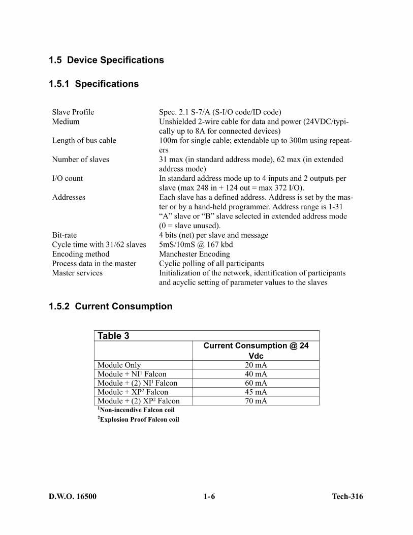
1.5 Device Specifications
1.5.1 Specifications
1.5.2 Current Consumption
Slave Profile Spec. 2.1 S-7/A (S-I/O code/ID code)Medium Unshielded 2-wire cable for data and power (24VDC/typi-
cally up to 8A for connected devices)Length of bus cable 100m for single cable; extendable up to 300m using repeat-
ersNumber of slaves 31 max (in standard address mode), 62 max (in extended
address mode)I/O count In standard address mode up to 4 inputs and 2 outputs per
slave (max 248 in + 124 out = max 372 I/O). Addresses Each slave has a defined address. Address is set by the mas-
ter or by a hand-held programmer. Address range is 1-31 “A” slave or “B” slave selected in extended address mode (0 = slave unused).
Bit-rate 4 bits (net) per slave and messageCycle time with 31/62 slaves 5mS/10mS @ 167 kbdEncoding method Manchester EncodingProcess data in the master Cyclic polling of all participantsMaster services Initialization of the network, identification of participants
and acyclic setting of parameter values to the slaves
Table 3Current Consumption @ 24
VdcModule Only 20 mAModule + NI1 Falcon 40 mAModule + (2) NI1 Falcon 60 mAModule + XP2 Falcon 45 mAModule + (2) XP2 Falcon 70 mA1Non-incendive Falcon coil2Explosion Proof Falcon coil
6

2 Installation Instructions
Mounting 2-2
Pneumatic Connections 2-3Tubing and Fittings 2-3Porting 2-4Maintenance 2-4
Switch Adjustment 2-5
Wiring Instructions 2-6APAC Connector Pin-out Diagrams 2-8
AS-i Supported Topologies 2-9
D.W.O. 16500 2- Tech-316
IMPORTANT: If the valve monitor is already in the field mounted on an actuator and valve, please follow the field wiring instructions in Section 2.3.
Confirm that the area is known to be non-hazardous before opening the cover of a network monitor and making or breaking any electrical connections.
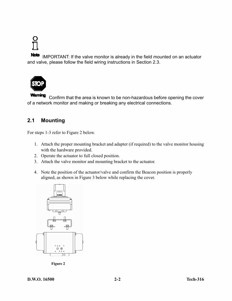
2.1 Mounting
For steps 1-3 refer to Figure 2 below.
1. Attach the proper mounting bracket and adapter (if required) to the valve monitor housing with the hardware provided.
2. Operate the actuator to full closed position. 3. Attach the valve monitor and mounting bracket to the actuator.
4. Note the position of the actuator/valve and confirm the Beacon position is properly
aligned, as shown in Figure 3 below while replacing the cover.
Figure 2
2

D.W.O. 16500 2- Tech-316
Figure 3
2.2 Pneumatic Connections
Personal injury and/or property damage may occur from loss of process control if the supply medium is not clean, dry oil-free air or non-corrosive gas. Instrument quality air that meets the requirements of ISA Standard S7.3-1975 is recommended for use with pneumatic equipment in process control environments. Westlock Controls recommends the use of a 20 micron filter with all Falcon solenoids.
2.2.1 Tubing and Fittings
The use of copper, stainless steel, nylon or polyethylene tube is recommended for piping up air circuits and equipment. As a general rule, pipe threaded fittings should not be assembled to a spe-cific torque because the torque required for a reliable joint varies with thread quality, port and fit-ting materials, sealant used, and other factors. The suggested method of assembling pipe threaded connections is to assemble them finger tight and then wrench tighten further to a specified number of turns from finger tight. The assembly procedure given below is for reference only; the fitting should not be over tightened for this will lead to distortion and most likely, complete valve failure.
1. Inspect port and connectors to ensure that the threads on both are free of dirt, burrs and exces sive nicks.
CLOSED
OPEN
CLOSED
OPEN
OPEN
Valve inPosition
CLOSED
Valve inPosition
3

D.W.O. 16500 2- Tech-3164
2. Apply sealant/lubricant or Teflon tape to the male pipe threads. With any sealant tape, the first one or two threads should be left uncovered to avoid system contam-ination.
3. Screw the connector into the port to the finger tight position.4. Wrench tighten the connector approximately 1 - 2 turns (to seal) from finger tight.
Again this is only reference - the fitting should NOT be over tightened.
Delrin valve bodies are fitted with hellicoils therefore an extra effort should be made NOT to over tighten pipe fittings or retaining screws (.5 - 1 turns from finger tight to seal). Over tightening will result in valve failure or pull hellicoils from valve body.
2.2.2 Porting
Figure 4
2.2.3 Maintenance
Routine maintenance is usually confined to the periodic replenishment of Dow Corning III lubricant or equivalent to spool and spring.
(Air Line) Designation1/4” NPT air ports for inlet, outlet, and exhaust
Description of Operation: Solenoid De-energized -air flows from Inlet Port 1 to Outlet Port 2 and
exhausts from Port 4 to Port 5. Solenoid Energized -air flows from Inlet Port 1 to Outlet Port 4 and
exhausts from Port 2 to Port 3.
Description of Operation: Solenoid De-energized -air flows from Outlet Port 2 to Exhaust Port 3.
Solenoid Energized - air flows from Inlet Port 1 toOutlet Port 2.
(3.5 Cv valve has 1/2” NPT air ports)
Spring Return ValveSpring Return Valve
42
53
12
31

D.W.O. 16500 2- Tech-316
2.3 Switch Adjustment
Switches are factory set. If you need to adjust switches for any reason follow instructions below.
For steps 1-8 refer to Figures 1 and 5.
1. Refer to Figure 1 and note the approximate locations of the Open and Close targets on the APAC module.
2. With the valve in the closed position, lift bottom cam of the Close sensor trigger.3. Turn cam until face of trigger is perpendicular to the target and sensor is activated as evi-
denced by the lighting of the corresponding module LED.4. Release the cam and the spring will push cam back onto the splined shaft. 5. Operate the actuator to the opened position. 6. Push down the top cam of the Open sensor trigger.7. Turn cam until face of trigger is perpendicular to the target and sensor is activated as evi-
denced by the lighting of the corresponding module LED.8. Operate actuator from one extreme to the other several times to check Limit Sensor
operation.
Figure 5
Push down,turn and release
Lift up,turn and release
Magnet embeddedin cam
5

D.W.O. 16500 2- Tech-3166
2.4 Wiring Instructions
All wiring must be in accordance with National Electrical Code (ANSI-NFPA-70) for the appropriate area classifications.
All wiring must be in accordance with National Electrical Code (ANSI-NFPA-70) for area classifications. The valve monitors are approved as nonincendive for Class I, Division 2, Groups A,B,C and D; dust-ignition proof for Class II/III, Division 1, Groups E,F and G hazardous (classified) locations; indoor/outdoor (NEMA type 4, 4X).
Always check the nameplate to make sure the agency approval ratings coincide with the application.
The proper wiring diagram for your unit is shown on the inside of the enclosure cover.
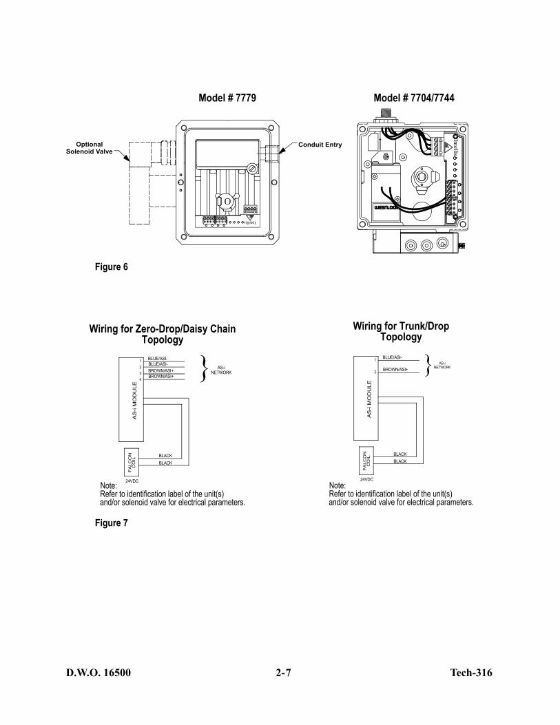
1. Wiring options for 7704, 7744 and 7779 are shown in Figures 6 and 7 below. 2. Replace the electronics housing cover or junction housing cover.3. Unit is now ready for automatic operation. If any assistance is required, please call West-
lock Controls at (201) 794-7650.
D.W.O. 16500 2- Tech-316
OptionalSolenoid Valve
Conduit Entry
}
AS
-i M
OD
ULE
FA
LCO
NC
OIL
BLACKBLACK
24VDC
BLUE/ASI-
BROWN/ASI+
1234
AS-iNETWORK
BLUE/ASI-
BROWN/ASI+
Note:Refer to identification label of the unit(s)and/or solenoid valve for electrical parameters.
Figure 7
Wiring for Zero-Drop/Daisy ChainTopology
Note:Refer to identification label of the unit(s)and/or solenoid valve for electrical parameters.
Wiring for Trunk/DropTopology
Intellis
IntellisModel # 7779 Model # 7704/7744
}A
S-i
MO
DU
LEF
ALC
ON
CO
IL
BLACKBLACK
24VDC
BLUE/ASI-
BROWN/ASI+
1
3
AS-iNETWORK
Figure 6
7

D.W.O. 16500 2- Tech-316
2.4.1 APAC Connector Pin-out Diagrams
1
3
42
“MINI” CONNECTORFEMALE
Figure 2
1
3
4 2
“MINI” MALEFIELD WIREABLE
Figure 34-PIN 4-PIN
34
1
2
M12 FEMALE“MICRO” CONNECTOR
Figure 54-PIN
M12 MALE“MICRO” CONNECTOR
Figure 44-PIN
3
2
1
4
Figure 15 – Pin Open Connector
View From Top
Plug(Female contacts)
Receptacle(Male contacts)
5
4
3
2
1
Pin 1/ ASI+/BrownPin 2/ NCPin 3/ ASI-/BluePin 4/ NC
4-Pin Open Connector
Pin 1/ ASI-/BluePin 2/ ASI-/BluePin 3/ ASI+/BrownPin 4/ ASI+/Brown
8
D.W.O. 16500 2- Tech-316
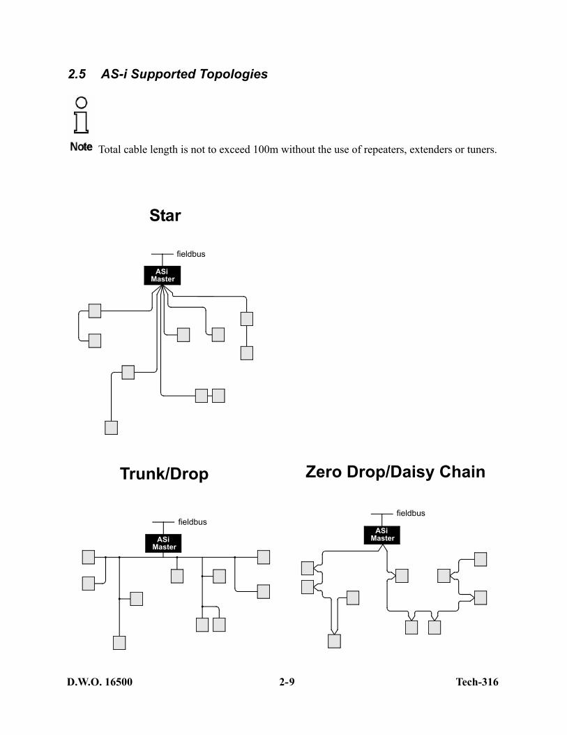
Star
2.5 AS-i Supported Topologies
Total cable length is not to exceed 100m without the use of repeaters, extenders or tuners.
Trunk/Drop
ASi
fieldbus
Master
Zero Drop/Daisy Chain
ASi
fieldbus
Master
ASi
fieldbus
Master
9

D.W.O. 16500 Tech-316
3 AS-i Communications Overview
AS-i Message Framing 3-2AS-i Master Output Bit Map 3-3AS-i Master Input Bit Map 3-3
D.W.O. 16500 3- Tech-316
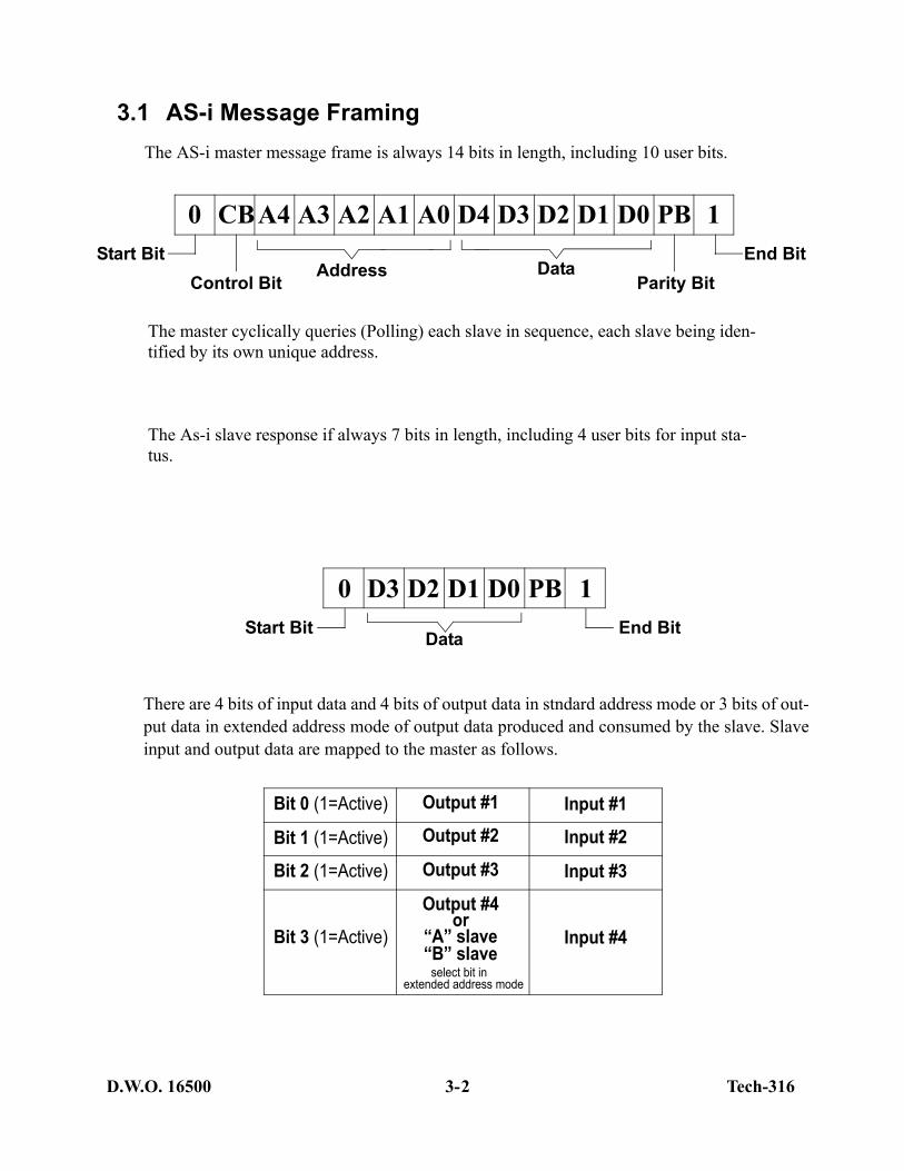
3.1 AS-i Message FramingThe AS-i master message frame is always 14 bits in length, including 10 user bits.
The master cyclically queries (Polling) each slave in sequence, each slave being iden-tified by its own unique address.
The As-i slave response if always 7 bits in length, including 4 user bits for input sta-tus.
There are 4 bits of input data and 4 bits of output data in stndard address mode or 3 bits of out-put data in extended address mode of output data produced and consumed by the slave. Slaveinput and output data are mapped to the master as follows.
0 D3 D2 D1 D0 PB 1
DataStart Bit End Bit
Bit 0 (1=Active)
Bit 1 (1=Active)
Bit 2 (1=Active)
Bit 3 (1=Active)
Output #1
Output #2
Output #3
Output #4
Input #1
Input #2
Input #3
Input #4or
“A” slave“B” slave
select bit in extended address mode
0 CBA4 A3 A2 A1 A0 D4 D3 D2 D1 D0 PB 1
Address DataControl Bit
Start BitParity Bit
End Bit
2
D.W.O. 16500 3- Tech-316
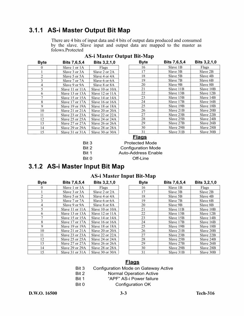
3.1.1 AS-i Master Output Bit MapThere are 4 bits of input data and 4 bits of output data produced and consumedby the slave. Slave input and output data are mapped to the master asfolows.Protected
AS-i Master Output Bit-Map
3.1.2 AS-i Master Input Bit Map
Byte Bits 7,6,5,4 Bits 3,2,1,00 Slave 1 or 1A Flags1 Slave 3 or 3A Slave 2 or 2A2 Slave 5 or 5A Slave 4 or 4A3 Slave 7 or 7A Slave 6 or 6A4 Slave 9 or 9A Slave 8 or 8A5 Slave 11 or 11A Slave 10 or 10A6 Slave 13 or 13A Slave 12 or 11A7 Slave 15 or 15A Slave 14 or 14A8 Slave 17 or 17A Slave 16 or 16A9 Slave 19 or 19A Slave 18 or 18A
10 Slave 21 or 21A Slave 20 or 20A11 Slave 23 or 23A Slave 22 or 22A12 Slave 25 or 25A Slave 24 or 24A13 Slave 27 or 27A Slave 26 or 26A14 Slave 29 or 29A Slave 28 or 28A15 Slave 31 or 31A Slave 30 or 30A
Byte Bits 7,6,5,4 Bits 3,2,1,016 Slave 1B Flags17 Slave 3B Slave 2B18 Slave 5B Slave 4B19 Slave 7B Slave 6B20 Slave 9B Slave 8B21 Slave 11B Slave 10B22 Slave 13B Slave 12B23 Slave 15B Slave 14B24 Slave 17B Slave 16B25 Slave 19B Slave 18B26 Slave 21B Slave 20B27 Slave 23B Slave 22B28 Slave 25B Slave 24B29 Slave 27B Slave 26B30 Slave 29B Slave 28B31 Slave 31B Slave 30B
Byte Bits 7,6,5,4 Bits 3,2,1,016 Slave 1B Flags17 Slave 3B Slave 2B18 Slave 5B Slave 4B19 Slave 7B Slave 6B20 Slave 9B Slave 8B21 Slave 11B Slave 10B22 Slave 13B Slave 12B23 Slave 15B Slave 14B24 Slave 17B Slave 16B25 Slave 19B Slave 18B26 Slave 21B Slave 20B27 Slave 23B Slave 22B28 Slave 25B Slave 24B29 Slave 27B Slave 26B30 Slave 29B Slave 28B31 Slave 31B Slave 30B
Byte Bits 7,6,5,4 Bits 3,2,1,00 Slave 1 or 1A Flags1 Slave 3 or 3A Slave 2 or 2A2 Slave 5 or 5A Slave 4 or 4A3 Slave 7 or 7A Slave 6 or 6A4 Slave 9 or 9A Slave 8 or 8A5 Slave 11 or 11A Slave 10 or 10A6 Slave 13 or 13A Slave 12 or 11A7 Slave 15 or 15A Slave 14 or 14A8 Slave 17 or 17A Slave 16 or 16A9 Slave 19 or 19A Slave 18 or 18A
10 Slave 21 or 21A Slave 20 or 20A11 Slave 23 or 23A Slave 22 or 22A12 Slave 25 or 25A Slave 24 or 24A13 Slave 27 or 27A Slave 26 or 26A14 Slave 29 or 29A Slave 28 or 28A15 Slave 31 or 31A Slave 30 or 30A
FlagsBit 3Bit 2Bit 1Bit 0
Protected ModeConfiguration Mode
Auto-Address EnableOff-Line
AS-i Master Input Bit-Map
FlagsBit 3Bit 2Bit 1Bit 0
Configuration Mode on Gateway ActiveNormal Operation Active“APF” AS-i Power failure
Configuration OK
3

1
Appendix A
Contact Information
USAWestlock Controls Corp.280 Midland Ave.Saddle Brook, NJ 07663Phone: (201) 794-7650 • Fax: (201) 794-0913Email: [email protected] http://www.westlockcontrols.com
EuropeWestlock Controls UKChapman Way, Tunbridge WellsKent, England TN23EFPhone: 011-441-892-519046 • Fax: 011-441-892-516279
South AmericaWestlock Equipmentos De Controles Ltda.Rua, Sao Paulo 291Alphaville, BarueriSao Paulo, CEP 06465-130Phone: 011-55-11-7291-0930 • Fax: 011-55-11-7291-0931


![APPARATUS FOR UNSHIELDED TWISTED PAIR (UTP) CABLES ... · 1.3 Unshielded twisted pair cable [2] Nowadays most networks are constructed using unshielded twisted pair cable (UTP). As](https://img.pdfslide.net/doc/110x75/5f9fd0db5f2ede190b2c6418/apparatus-for-unshielded-twisted-pair-utp-cables-13-unshielded-twisted-pair.jpg)