Embed Size (px)
Citation preview

Design Features
Description of Operation
Damper Specifi cations
System Application and Design
SC1578EW 05/17
Inte
lliZ
on
e2 S
pecifi c
ati
on
Cata
log
an
d D
esi
gn
Gu
ide
Six Zone Capability
Comfort Zoning System
res
f Operation
ifi cations
cation and Design
Inte
lliZ
on
e2
Sp
ecifi
cati
on


INTELLIZONE2 SPECIFICATION CATALOG
Table of Contents
IntelliZone2 . . . . . . . . . . . . . . . . . . . . . . . . . . . . . . . . . . . . . . . . . . . . . . . . . . . . . . . . . . . . . . . . . . . . . . . 4
Introduction . . . . . . . . . . . . . . . . . . . . . . . . . . . . . . . . . . . . . . . . . . . . . . . . . . . . . . . . . . . . . . . . . . . . . . 5
IntelliZone2 Features. . . . . . . . . . . . . . . . . . . . . . . . . . . . . . . . . . . . . . . . . . . . . . . . . . . . . . . . . . . . . . . 6
Design Features . . . . . . . . . . . . . . . . . . . . . . . . . . . . . . . . . . . . . . . . . . . . . . . . . . . . . . . . . . . . . . . . . . . 7
IntelliZone2 Components . . . . . . . . . . . . . . . . . . . . . . . . . . . . . . . . . . . . . . . . . . . . . . . . . . . . . . . . . . . 8
IntelliZone2 Configuration . . . . . . . . . . . . . . . . . . . . . . . . . . . . . . . . . . . . . . . . . . . . . . . . . . . . . . . .9-16
Description of Operation . . . . . . . . . . . . . . . . . . . . . . . . . . . . . . . . . . . . . . . . . . . . . . . . . . . . . . . . . . .17
Blower Data. . . . . . . . . . . . . . . . . . . . . . . . . . . . . . . . . . . . . . . . . . . . . . . . . . . . . . . . . . . . . . . . . . . . 18-21
Wiring Schematic. . . . . . . . . . . . . . . . . . . . . . . . . . . . . . . . . . . . . . . . . . . . . . . . . . . . . . . . . . . . . . . . . 22
Damper Specifications . . . . . . . . . . . . . . . . . . . . . . . . . . . . . . . . . . . . . . . . . . . . . . . . . . . . . . . . . . . . 23
Zone Selection . . . . . . . . . . . . . . . . . . . . . . . . . . . . . . . . . . . . . . . . . . . . . . . . . . . . . . . . . . . . . . . . 24-25
Special Zoning Applications . . . . . . . . . . . . . . . . . . . . . . . . . . . . . . . . . . . . . . . . . . . . . . . . . . . . . . . 26
Peak Heating and Cooling Demands . . . . . . . . . . . . . . . . . . . . . . . . . . . . . . . . . . . . . . . . . . . . . . . . 27
System Sizing . . . . . . . . . . . . . . . . . . . . . . . . . . . . . . . . . . . . . . . . . . . . . . . . . . . . . . . . . . . . . . . . . 28-29
Description of Operation . . . . . . . . . . . . . . . . . . . . . . . . . . . . . . . . . . . . . . . . . . . . . . . . . . . . . . . .31-32
SAH 5 Speed ECM Blower Performance Data Option A . . . . . . . . . . . . . . . . . . . . . . . . . . . . 33-34
Blower Performance Data Option C. . . . . . . . . . . . . . . . . . . . . . . . . . . . . . . . . . . . . . . . . . . . . . 35-36
Split Wiring Schematic . . . . . . . . . . . . . . . . . . . . . . . . . . . . . . . . . . . . . . . . . . . . . . . . . . . . . . . . . 37-39
Revision Guide . . . . . . . . . . . . . . . . . . . . . . . . . . . . . . . . . . . . . . . . . . . . . . . . . . . . . . . . . . . . . . . . . . . 41

4
INTELLIZONE2 SPECIFICATION CATALOG
The IntelliZone2 Comfort Zoning System is a
residential and/or commercial zone control
system which works with 5 and 7 Series units
(up to 6 tons) to space condition up to six
zones. Each zone is controlled by its own
space thermostat and damper motor(s) using
a maximum 1-inch W.G. inlet static pressure at
zone dampers. The IntelliZone2 monitors the
thermostats, puts the system in the proper mode
of operation, and energizes the correct number of
stages of heating or cooling and airflow.
The IntelliZone2 was designed to solve problems that are inherent with the concept of HVAC zoning by:
• Eliminating the bypass damper;
• Applying the ECM blower motor to zoning;
• Using “Multiple Level” zone calls (Heating 0-3, Cooling 0-2), allowing the controller to better estimate the
demand of each zone and thus condition space most efficiently; and
• Designing a high value control which is both easy to install and service.
• Capable of full communication and control of the variable speed compressor bearing 7 Series
The IntelliZone2 System is a perfect match to 5 and 7 Series geothermal systems, extending comfort and energy savings
farther than ever before. The IntelliZone2 is also compatible with our Symphony/AWL Wi-Fi Smart Comfort System.
WaterFurnace International’s corporate headquarters and manufacturing facility is located in Fort Wayne, IN. A scenic
three-acre pond located in front of the building serves as our geothermal heating and cooling source to comfort-condition
our 110,000 square feet of manufacturing and office space. As a pioneer, and now a leader in the industry, the team of
WaterFurnace engineers, customer support staff and skilled assembly technicians is dedicated to providing the finest
comfort systems available. With Factory ISO 9001 and engineering laboratory ISO 17025 certifications, you are assured of a
quality designed and manufactured product.
By choosing or specifying WaterFurnace IntelliZone2™ Series products, you can be assured that your customer is investing
in an exceptional comfort system and peace of mind for many years to come.

5
INTELLIZONE2 SPECIFICATION CATALOG
IntroductionThe IntelliZone2 Comfort Zoning system is to be used only
with heat pumps/air handlers equipped with Aurora AXB
or AHB controls. A package unit must have ABC and AXB
to be compatible with IntelliZone2. A split system with
air handler must have ABC and either AXB or AHB (in
air handler) to be compatible with the IntelliZone2. If the
heat pump or air handler do not have Aurora AXB or AHB
controls you must use IntelliZone2•24V Comfort Zoning
system.
Zoning is a method of ensuring that all areas of a home or
building receive the right amount of heating or cooling.
Zoning allows the occupant to independently control the
temperature in each area of the building. If desired, all
areas can be adjusted for occupancy patterns and uses.
IntelliZone2Thermostat Zone Damper Supply Register
Geothermal Unit
IntelliZone2 Control
BasementZone
Main Living Area Zone
Master Suite Zone
Bedrooms Zone
The above illustration is representational and is not intended as a guide for IntelliZone2 system installation.
Zoning is particularly useful where normal heat distribution
patterns result in uneven temperature control. For example,
a building that is partly below grade can use zoning
to eliminate uneven temperature control between the
basement and the rest of the building. Large buildings that
might have long, unequal length duct runs can use zoning
to equalize the delivery of conditioned air. Buildings with
many large windows can use zoning to compensate for
solar heat gain and radiation losses at night.
Along with providing comfort, zoning can provide energy
savings by keeping various zones at desired set points
without over-cooling or overheating. In effect, zoning
mandates that the heating/cooling system condition only
the portions (or zones) of the building which need to be
conditioned. This translates into shorter compressor run
times and ultimately lower space conditioning bills.

6
INTELLIZONE2 SPECIFICATION CATALOG
IntelliZone2 Features
IntelliZone2 Features• Up to 6 zone possible in variable speed systems
(maximum of 4 for dual capacity units and 2 for single speed units)
• 4.3 in. Color touchscreen master thermostat for ease of use• TPCC32U01, ZoneStat, SensorStat or SensorStat Remote
Kit options for zones 2-6• Full communicating system for advanced features:• Full text Faults/Alarms from IZ2 and 5 or 7 Series heat pump• Adjust zone setpoints from Masterstat or Zonestat• Full features of 5 and 7 Series heat pumps are
communicated including faults, energy monitoring, superboost cooling mode and active dehumidification
- Full zone setback programming from each zone.- Dealer configuration mode- Full color touchscreen troubleshooting display
• No bypass damper or dump zone needed.• 2 (spring) or 3 wire damper options.• Central Zone option operates all dampers open
on temperature measurement from MasterStat for construction or service operation.
• Economy/comfort settings for each zone to reduce operating costs In less important rooms.
• Zones are 'sized' to provide more proper compressor and blower staging.
• Staging flexibility allows several up/down staging options for customization to your application.
• Full Aurora controls capability
Flexibility in Zone Comfort ControlThe IntelliZone2 allows comfort or economy mode selections for each zone.
In ‘Comfort Mode’ a single zone call for conditioning will engage the compressor and allow a minimal set point variation, thus providing ultimate comfort. However in ‘Economy Mode’ a single zone call for conditioning will be ignored until either a next level call for that zone or a second zone call occurs. This will allow slightly greater temperature fluctuations in these zones allowing lower operating costs in areas such as rec rooms, unused bedrooms where slightly higher temperature variation would not be noticeable.
Flexibility in System Staging(single or dual capacity equipment)The IntelliZone2 System allows four different staging options for both heating and cooling. Once the compressor call has been initiated by a zone, the compressor will be upstaged using one of four staging options in single, dual, or variable capacity equipment. The modes are Normal, Quicker, Faster1 and Faster2. More detail is listed later in this document.
Eliminating Bypass DamperBy utilizing the full functionality of the ECM blower motor, the bypass damper can be eliminated from the zone system. In effect, the ECM replaces the bypass damper.
In conventional systems, the air handling device can deliver airflow only at one or two levels, which means a significant amount of excess air must be “bypassed” to the return. By
looking at which zones are calling, the IntelliZone2 determines the most efficient compressor and blower speeds. Since the IntelliZone2, with its six/eight speeds on-line at all times, has the ability to deliver the correct amount of airflow that the structure is calling for, there is no need for bypass.
When utilized properly, the ECM motor will provide precise airflow control for a given space. The ECM will operate on up to six/eight pre-configured airflow levels depending on the load requirements of the house. All airflow is setup for the 5 or 7 Series in the AID Tool. If the IntelliZone2 is controlling:
• 5 Series single or dual-capacity unit, there will be 6 total airflow levels, two airflow levels for low-speed compressor operation and two airflow levels for high-speed compressor operation and one for continuous blower and one for auxiliary heat.
• 7 Series variable speed unit, there will be 8 total airflow levels, one airflow level continuous blower and auxiliary heat settings and six airflow levels for the variable speed compressor ranging from 25, 40, 55, 70, 85, and 100% airflow depending upon the zone call.
By varying the airflow level per the needed output capacity of the heat pump, bypass is eliminated and the correct amount of air is delivered to the house. Consult the 5 and 7 Series technical literature for more information on airflow setup.
Efficient Space ConditioningTraditional zone control systems control single-speed compressors and single-speed blowers and typically use single heating and cooling calls to determine space conditioning needs. By operating at only one capacity level, these traditional systems are seriously handicapped in their ability to handle the varying load of the structure.
The IntelliZone2 control system controls the dual-capacity and variable speed compressor as well as the ECM variable-speed blower, coupling this variable capacity equipment with multiple level zone calls allows the IntelliZone2 to exactly match the demands of the space.
One of the goals of the IntelliZone2 system is to minimize compressor and blower operation by operating at the lowest, most efficient speed possible. The IntelliZone2 makes logic decisions which minimize compressor run-times and help decrease energy cost. For example: If one or more zones have Y1 demand calls, the thermostat has determined that the particular zones need conditioning, but the demand is at a low level. The IntelliZone2 control algorithm will take these low level calls and determine what compressor capacity with the proper airflow will satisfy the zone calls. Thus, the system operates in lower capacity most of the time and intelligently provides cost-efficient space conditioning control.
Many times, as in any structure, the space conditioning peak load for each zone can happen at a different time throughout the day. This may be due to sun, wind, or even the zone use. This diversity can sometimes allow slightly smaller capacity equipment to condition one zone during its morning peak and then condition another during its afternoon peak, whereas an unzoned structure would have to be sized with larger capacity equipment to condition both areas at once.

7
INTELLIZONE2 SPECIFICATION CATALOG
Design Features
Full Color Touchscreen Display and Diagnostic LEDs With traditional zone control systems, the installer typically
has a difficult time determining the status of the inputs and
outputs of the zone control board. The IntelliZone2 System
employs an LED for each output and the MasterStat color
display shows all inputs and outputs. With just a glance,
the installer is able to quickly determine what inputs the
IntelliZone2 is receiving and what outputs the IntelliZone2
is sending to the unit.
Application Flexibility• Multiple level zone calls communicate exact zone load
requirements for intelligent equipment control.
• Controls up to six zones with variable speed compressor
(four with dual-capacity and two zones with single-
speed compressor).
• Control of ECM blower motor to match needs of the
space. Six/eight blower speeds are available at all times.
• Zone size as small as 15% of whole house with
variable speed compressor (25% dual-capacity and 50%
single speed).
• Individual zone-selectable economy or comfort modes.
• Four staging options (normal, quicker, faster1 and
faster2) to allow a wide range of comfort and energy
consumption solutions.
• Separate staging options for heating and cooling
provides better comfort.
• Dehumidification mode lowers airflow in cooling for
better dehumidification.
• Simple, reliable thermostat operation; simple
programming for the homeowner.
IntelliZone2's Sophisicated Microprocessor Controlwith LEDs to Display Inputs and Outputs
• Individual zone-selectable continuous or
intermittent blower.
• Smart algorithm serves simultaneous heating and
cooling demands.
• Reduces blower power consumption.
• Installation and Service Advantages
• Bypass damper not needed (minimal oversizing of
ductwork may be desired).
• All low voltage wiring (24VAC).
• Central mode control for temporary conditioning of the
whole house using one thermostat.
• Low cost communicating zone thermostats.
• Three-wire or two-wire damper actuators for maximum
performance and reliability.
• Transformer with integrally mounted circuit breaker.
• LED indicators (damper operation, mode, fault) and
troubleshooting screens displayed on MasterStat for
easy diagnostics.

8
INTELLIZONE2 SPECIFICATION CATALOG
IntelliZone2 Components
IntelliZone2 Relay Board (Firmware Version 2.01 or Later)
The IntelliZone2 relay board provides basic relay logic for the damper
operation and serves as a common connection point for all IntelliZone2
thermostats and the heat pump.
IntelliZone2 MasterStatThe IntelliZone2 MasterStat is the master control for the system and has all
of the programming for operation. It is a 4.3 in. communicating color touch
screen device that also functions as a zone thermostat for Zone 1. Optional
remote sensor capability is also available.
IntelliZone2 ZoneStat (Optional)
The IntelliZone2 ZoneStat is a zone thermostat option for any of Zones 2
through 6. It has full setback capability and communicates to the
IntelliZone2 system.
IntelliZone2 SensorStat (Optional)The IntelliZone2 SensorStat is a zone thermostat option for any of Zones 2
through 6. It has full setback capability (through the MasterStat interface
only) and communicates to the IntelliZone2 system.
IntelliZone2 Outdoor SensorThe IntelliZone2 Outdoor Sensor measures the outdoor temperature and
communicates to the IntelliZone2 system. This temperature is displayed on
the MasterStat, and also used to balance response as well as auxiliary electric
heat use. The Outdoor Sensor is included in every IntelliZone2 kit.
TPCC32U01 (Optional) (Firmware Version 3.01 or Later)
The TPCC32U01 is a 4.3in communicating color touch screen device that
can be used as a zone thermostat for zones 2 through 6. It has full set back
capability and communicates to the IntelliZone2 System.
SensorStat-Remote-Kit (Optional)
The SensorStat-Remote-Kit is an option for an invisible thermostat installation
and communicates with the IntelliZone2 relay panel. The kit will include
the SensorStat Remote, TSU03 (mud in sensor) and wire nuts. This kit will
monitor the zone temperature in zones 2 through 6. All set point adjustments
are made at the MasterStat.

9
INTELLIZONE2 SPECIFICATION CATALOG
IntelliZone2 Confi guration
Aurora System and Communication Configuration of IntelliZone2 Aurora Communication BasicsThe Aurora Control functions around the concept of modularity and intercommunications between these boards. The communication is a 4 wire ModBus protocol. ModBus protocol is an open source protocol becoming more popular with equipment manufacturers for use in HVAC equipment. The Aurora has one ‘bus’ for the ABC, AXB, AHB, AWL, VS Drive, EEV, and thermostats. The AID Tool only plugs into the ABC AID Tool port, SAH Air Handler AID Tool port or the AWL (RJ style connector) and will not work at any other location. The AXB has 3 other independent ports for differing protocols; for IntelliZone2, ClimateTalk Components, and Communicating ECM blower motors. None of these ports comply with the ModBus protocol set up for the rest of the Aurora system.
The ModBus communication is accomplished within the cabinet using shielded and ground cabling. This shield is most important in 7 Series applications where the VS Drive component, by its very nature, emits electro-magnetic interference and can interfere with ModBus communications. Round ferrite ‘donuts’ can be observed at various locations to aid in cleaning the communication lines. Each line is comprised of an R (+24VAC), C (common) and a ‘+’ and ‘-‘ communication line. At times the ‘R’ and ‘C’ lines may not be connected or needed. The terminals marked ‘+’ and ‘-‘ should not be switched, although damage may not occur to the boards, communication is not possible. The communication voltage and current are small therefore 24 awg wire is adequate for these communication lines and a shield is not required but recommended in high EMI environments.
An extra ‘expansion’ connector is available for connecting other devices onto the main ABC ModBus.
A small LED is located next to each of the communication ports to aid in evaluating active communication at that specific port. This is true for each board. The blinking indicates transmission or receiving communication activity.
Configuring the Aurora for the IntelliZone2 'Adding' the IntelliZone2 to the Aurora system can be accomplished using the AID Tool via the 'Config Aurora' screen and scrolling to IntelliZone2 selecting and adding. As always a 'Y' in the communication column shows that communication is OK. This will initiate communication between the IntelliZone2 system and the Aurora AXB/ABC.
Software VersionsSoftware versions of the IntelliZone2 MasterStat can be found in the startup screen or in the AID Tool Aurora Config screen. Software can be uploaded to the MasterStat via the USB port on the thermostat. Consult your local WaterFurnace representative or tech service for details.
Wiring and Configuring the Thermostats/Sensors The MasterStat and Zone Sensors should be wired using standard 4-wire thermostat cable (if issues with EMI, shielded cable should be used and grounded at the ‘–‘ terminal on one end). The other zones should be added sequentially on the relay board until complete. The dip switch on the back of each ZoneStat or SensorStat should be selected for the appropriate zone number; for instance, Zone 2 stat should be selected using the DIP switch on the back for ‘off, off, off’.
The TPCC32U01 will auto detect that it is attached to the IntelliZone2 relay panel and will display the screen below. Use the up/down arrows▲▼ to select the zone.
If more than one zone is assigned the same zone number an error will be displayed on the TPCC32U01 and Mas-terStat. After the initial confi guration to change the zone numbers enter the confi guration mode by a fi nger over the Zone number in the upper left hand corner for 5 sec. Select zone number and use the up/down arrow ▲▼ to adjust.
Config Aurora System
Dev Comm Ver ABC Y X.XX
AXB Y X.XX
Add Device Remove Device
Back
Option Enter

10
INTELLIZONE2 SPECIFICATION CATALOG
Once added to the Aurora system, the setup and configuration mode should be entered at the MasterStat by holding a finger over the IntelliZone2 logo for 5 sec. The Configuration and Setup mode will appear automatically. NOTE: These options are intended to be used by the installer. End users are not advised to change or modify any of these settings. Doing so may make your equipment stop working properly and/or may void the warranty of the zoning system as well as the equipment connected to the thermostat.
It should be noted that the MasterStat Z2TK troubleshooting
harness can be useful during setup by allowing the temporary
connection of the MasterStat directly at the IntelliZone2 relay
board for ease of configuration or servicing.
Equipment and Number of ZonesThe first screen is Equipment and # of Zones. Here the
total number of desired zones and the type of equipment
is selected. Equipment is automatically detected. Press the up and down arrows until the desired number of zones appears. The zones should always be installed sequentially starting with the MasterStat always in Zone 1.• Single speed equipment is limited to a maximum of
2 zones
• Dual Capacity equipment is limited to a maximum of4 zones
• Variable speed equipment can have up to the maximum of 6 zones.
NOTE: If the number of zones selected Is less than 6, the remaining zones will be disabled.
IntelliZone2 Confi guration cont.ZoneStats/SensorStats PCB
A+RCB- P
14 –
Zon
e 4
A+RCB- P
15 –
Zon
e 5
A+RCB-Zo
ne 4
Sta
t
On32 1
Zone 4 code shown
A+RCB-Zo
ne 5
Sta
tOn32 1
Zone 5 code shown
ZoneStat
SensorStat
Zone ID must be set for each Zone 2-6. ID can beconfirmed on ZoneStat by pressing cancel button for
5 sec. ID shown on display. See Zone ID Codes.
Zone ID must be set for each Zone 2-6. ID cannot beconfirmed on Zone SensorStat. See Zone ID Codes.
Relay Board
A+
R
C
B- P11
– Z
one
1M
aste
rSta
tDX+
R
C
DX-
Zone
1M
aste
rSta
t
MasterStat isalways Zone 1
S1
S2
IntelliZone2Relay Board
A+
R
C
B- P16
– Z
one
6DX+
R
C
DX-
S1
S2
Opt
iona
lR
emot
eS
enso
r IntelliZone2
Relay Board
MasterStat
TPCC32U01
On
32 1
On
32 1
On
32 1
Zone 4 Zone 5Zone 3On
32 1
Zone 2On
32 1
Zone 6Zone ID Codes
NOTES:1) Zone ID must be set for each Zone 2-6. ID can be confirmed on ZoneStat by pressing cancel button for 5 sec. ID shown on display.2) Small screw driver can be used to set ID thru protective plastic skin!3) MasterStat always Zone 1. Zone ID not necessary. 4) TPCC32U01 zone is set through its touchscreen.
(Note 4)
Opt
iona
lR
emot
eS
enso
r
P3 –
Mast
erSt
at Lo
cal
C
B-
A+
RZ2TK
Kit
IntelliZone2 Relay Panel
Use the Z2TK Harness to temporarily connect the IntelliZone2 MasterStatdirectly to the IntelliZone2 Relay Panel for ease of setup or troubleshooting.

11
INTELLIZONE2 SPECIFICATION CATALOG
Damper
The Damper screen allows the selection of either 2 wire (spring open) or 3 wire (power open/power closed) type.
StagingStaging allows custom selection of staging for cooling and
heating, independently.
The IntelliZone2 system allows separate staging options
for cooling and heating. There are four options for each
mode which are explained below. As an example, staging
for cooling can be set for ‘Normal’ while staging for heating
is set for ‘Faster2’. Allowing heating and cooling staging to
be independent of each other will provide better comfort
all year long. Once the compressor call has been initiated
by a zone, the compressor will be upstaged using one of
the four staging options.
Single and Dual Staging
Normal - This “as shipped” mode will upstage the blower
and compressor normally.
Quicker - This mode will upstage the blower, compressor
and auxiliary electric heat more expediently than “normal”
mode for increased comfort.
Faster1 - This mode allows for a timed element in
compressor (heating and cooling) and electric heat
(heating) upstaging in 45% and 70% zones for situations in
which ‘Quicker’ upstaging is inadequate. If the heat pump
is already operating in first stage and a 45% or 70% zone
has had a heating or cooling demand for 30 continuous
minutes then second stage will be activated. For heating,
if after another continuous 30 minutes the H3 demand is
still present from a 45% or 70% zone, third stage will be
activated until the zone call is reduced to a H2. Airflow will
increase with compressor staging/EH during this period.
For heating, if the heat pump is already operating in second
stage and a 45% or 70% zone has had a demand for 30
continuous minutes then third stage will be activated until
the demand is reduced to H2. Airflow will be increased to
EH selection during this period.
Faster2 - This mode allows for a timed element in compressor (heating and cooling) and electric heat (heating) upstaging in 45% and 70% zones for situations in which Faster 1 upstaging is inadequate. If the heat pump is already operating in first stage and a 45% or 70% zone has had a heating or cooling demand for 15 continuous minutes then second stage will be activated. For heating, if after another continuous 15 minutes the H3 demand is still present from a 45% or 70% zone, third stage will be activated until the zone call is reduced to a H2. Airflow will increase with compressor staging/EH during this period. For heating, if the heat pump is already operating in second stage and a 45% or 70% zone has had a demand for 15 continuous minutes then third stage will be activated until the demand is reduced to H2. Airflow will be increased to EH selection during this period.
Variable Speed StagingFor heating in all the staging options below, the total of the zone demands will determine when auxiliary heat is energized which could be anywhere from compressor speed 9 to speed 12. If auxiliary heat is energized while on compressor speed 9-11 the compressor speed automatically increases to speed 12. Airflow will increase with compressor speed/EH during this period.
Normal - This “as shipped” mode will upstage the blower and variable speed compressor normally.
Quicker - This mode will upstage the blower, compressor and auxiliary electric heat more expediently than “normal” mode for increased comfort. Generally the compressor will be upstaged 1 extra speed more than normal.
Faster1 - This mode allows for a timed element in compressor and electric heat upstaging in 45% and 70% zones for situations in which quicker staging is not meeting demand. When an H3 (heating) or C2 (cooling) demand is initially received the compressor will upstage two speeds more than normal. After 15 continuous minutes of an H3 or C2 demand the compressor will upstage one more compressor speed and will continue to upstage one compressor speed with every 15 minutes of a continuous H3 or C2 demand until auxiliary electric heat is energized for heating or maximum compressor speed for cooling.
Faster2 - This mode also allows for a timed element in compressor and electric heat upstaging in 45% and 70% zones for situations in which Faster1 is not meeting demand. When an H3 (heating) or C2 (cooling) demand is initially received the compressor will upstage two speeds more than normal. After 15 continuous minutes of an H3 or C2 demand the compressor will upstage two more compressor speeds and will continue to upstage two compressor speeds with every 15 minutes of a continuous H3 or C2 demand until auxiliary electric heat is energized for heating or maximum compressor speed for cooling.
IntelliZone2 Confi guration cont.

12
INTELLIZONE2 SPECIFICATION CATALOG
Zone ConfigurationZone configuration allows the selection of the zone size and the zone priority. The zone can be selected by touching the upper right screen text noting the zone. In this way you can cycle thru all of the active zones to view the configuration.
Zone PercentageSelecting the zone percentage can also be calculated by using the IntelliZone2 Calculator software. This percentage represents an approximation of the maximum heating or cooling load percentage of the zone and thus to a certain extent volume of airflow. The IntelliZone2 allows 0, 25, 45, and 70% selections. Some general rules to follow in this selection procedure are as follows:• Pick the larger percentage for major living areas such
as family rooms, etc.• Pick the smaller percentage for minor living areas such
as dens or bedrooms.• Pick a larger percentage if more branches are required
than the load indicates due to large area per load (i.e. unfinished insulated basement).
• The IntelliZone2 Design software should be used to aid in the selection and calculation of design cfm.
• The IntelliZone2 determines modes as a proportion of the total demand. A simple example of this to begin with is a two-zone system in the cooling mode. If each zone is set at 70% we have the following scenario:
Zone 1 = 50% Zone 2 = 50%
NOTE: All Zone % calculations are ‘normalized using the following process: We now must determine what percentage of the total load each zone represents. To perform this operation, add the two zones together 70 + 70 = 140. One zone would then be 70/140 or 50%.
The IntelliZone2 then reduces the total demand based upon thermostat demand. A “Y1” call in the above example will result in one half of the zone demand in this case 1/2 of 50% for a 25% system demand. A common complaint is insufficient cooling when only one zone is calling for cooling. The IntelliZone2 will not initiate a “Y2” output to the unit until it senses a 51% total system demand (This is when the IntelliZone2 is set for normal upstaging). If the IntelliZone2 is set for quicker upstaging it drops to the total system demand required 41% to initiate a Y2 output. By this example, it will require a “Y2” call from one zone (50%) and a “Y1” call from the second zone (25%). This will give us a total system demand of 50% + 25% = 75%. System demand for three- and four-zone systems are computed in the same manner.
Heating demand is determined in the same manner, but we now have a third stage instead of two for cooling. The IntelliZone2 assigns values as follows: Y1 = 40% Y2 = 80% Y3 = 100%
We know from the previous example that the IntelliZone2 will initiate a “Y2” output to the compressor when it is set to normal upstaging and 51% of total demand is needed. It will issue a “W” call to the unit when there is a 90% total demand.It is a common assumption that if you have a house with two zones equally divided each zone should be set at an equal amount, usually 70%. As can be seen in the above example, it will take a “Y3” call from one zone as well as a “Y2” call from the second zone to obtain auxiliary heat.
This is a simple example, but three- and four-zone systems are calculated in the same manner. Blower speeds are also assigned upon the percentage of system demand and a complete understanding of this process is not necessary for day-to-day decisions. As a serviceman, the temptation arises, in some instances, to influence the logic of the board by jumping “Y1” and “Y2”. While this will create a quicker response, the ductwork of that zone must be capable of handling the cfm delivered by the unit (i.e., if a “Y2” signal is given to the unit, can the ductwork handle the total cfm of the unit).
When setting up a new system remember that if you have unused zones they must be set to zero. If they are not, the setting that they have will be included in the total demand preventing the other zones from operating correctly, as there will be no inputs on those zones.
The IntelliZone2 allows the selection of either comfort or economy mode in each individual zone to provide maximum savings in areas that allow it (such as workshops and basements), while maintaining perfect comfort in the zones where accurate temperature is most desired (such as bedrooms and baths)
IntelliZone2 Confi guration cont.

13
INTELLIZONE2 SPECIFICATION CATALOG
IntelliZone2 Confi guration cont.Zone Priority
Comfort Mode - A single zone call (Y1) for conditioning will engage the compressor and allow a minimal set point variation, thus providing ultimate comfort.
Economy Mode - A single zone call (Y1) for conditioning will be ignored by the IntelliZone2 until either a Y2 call is initiated from the same zone or another zone calls for conditioning (Y1). This allows a slightly greater set point variation than in comfort mode. This setting prevents less important zones from energizing the compressor unless it is really needed, thus saving money. As a bonus in this mode, upon a Y1 call, the IntelliZone2 may try to precondition the zone with return air from other zones already satisfied and, in some cases, can preclude the need for energizing the compressor.
Variable Speed Fan Staging - Variable Speed Fan Staging allows the ability to expand the blower levels. Options are Normal and Expanded. There are three airflow speeds assigned to a compressor speed and the airflow level is determined by the fan demand total zone %. Normal is the recommended airflow level. Selecting Expanded will increase the highest airflow level by one level and decrease the lowest airflow level by one level from Normal. Not available for single speed or dual capacity models.
Zones - Displays the inputs that the IntelliZone2 is receiving.
Status - Displays the outputs that the IntelliZone2 is sending to the equipment.
Test Mode - In Test mode ‘Central Zone’ mode can be selected. In Central mode all dampers are opened and thermostat readings are taken ONLY from the Zone 1 MasterStat. This will approximate operation without a zone system (all dampers open and IntelliZone2 MasterStat temperature control) and can be useful during initial construction of the home or during service etc.Also in ‘Central Zone’ mode each damper can be individually cycled off/on to verify operation during Installation or service. It should be noted that the MasterStat Z2TK troubleshooting harness can be useful here by allowing the temporary connection of theMasterStat directly at the IntelliZone2 relay board for ease of configuration or servicing.
Thermostat TypeNORMAL/DUAL FUEL
Normal - used for normal operation Dual Fuel - used on dual fuel systems; needs outdoor sensor to lockout dual fuel

14
INTELLIZONE2 SPECIFICATION CATALOG
IntelliZone2 Confi guration cont.Dual Fuel (Single Speed/Dual Capacity) - When Dual Fuel
is selected for 'Thermostat Type' and a 'W' call is present
operation will be as follows:
1. The temperature will be controlled by the MasterStat
while other zones are ignored.
2. All zone dampers will open, Y1, Y2, G, W outputs shall
run for 60 seconds. After 60 seconds Y1 and Y2 will be
dropped and output only W and G (if Fan with Heat
Option is selected otherwise G will be dropped).
3. There will be a two minute minimum run time once
Dual Fuel operation has been entered, regardless if
MasterStat heat call has been satisfied.
4. Once the two minute minimum run time expires and
the 'W' call is satisfied at the MasterStat then Dual Fuel
operation will be terminated. There will be no down
staging.
5. Once Dual Fuel operation is terminated all zone
dampers will close.
6. There will be a 4 minute time delay once Dual Fuel
operation is terminated before compressor operation
for cooling or heating may begin.
Dual Fuel (Variable Speed) - When Dual Fuel is selected
for 'Thermostat Type' and a 'W' call is present operation
will be as follows.
1. The temperature will be controlled by the MasterStat
while other zones are ignored.
2. All zone dampers will open, the current compressor
speed, G and W outputs shall run for 60 seconds. After
60 seconds the compressor will be stopped and output
only W and G (if Fan with Heat Option is selected
otherwise G will be dropped).
3. There will be a two minute minimum run time once
Dual Fuel operation has been entered, regardless if
MasterStat heat call has been satisfied.
4. Once the two minute minimum run time expires and
the 'W' call is satisfied at the MasterStat then Dual Fuel
operation will be terminated. There will be no down
staging.
5. Once Dual Fuel operation is terminated all zone
dampers will close.
6. There will be a 4 minute time delay once Dual Fuel
operation is terminated before compressor operation
for cooling or heating may begin.
Fan with Heat Option (Dual Fuel Applications) - Options
are ON or OFF. This selection determines whether G (fan)
output is to be ON or OFF when W (auxiliary heat) output
is ON.
Aux Heat Lockout - Allows the configuration to lockout
electric heat above a selected outdoor temperature.
The outdoor sensor (OAT) must be installed on the
IntelliZone2 Relay Board. This setting is adjustable in 5°F
increments from NONE to 40°F. This will provide full heat
pump capacity without electric heat above the selected
temperature. When the outdoor temperature drops
below the selected temperature, then electric heat will be
energized when the demand is present.
DifferentialThis adjustment will vary the number of degrees, from
the set point, before a call for heating or cooling is made.
Adjustments can range between 0.2° and 4° differential.
Default is 0.5° differential. (If your set point is 70°F in
heating, your thermostat will not call for heat until the room
temperature is 69.5°F, when using a 0.5° differential setting.
OffsetsTemperature Offsets – This option allows calibration
(or deliberate miscalibration) of the room
temperature sensor(s). The Offset function
only works on the MasterStat. There are various
reasons why the displayed temperature would be
adjusted to a higher or lower value. NOTE: Do not
adjust for 30 minutes after installation because
board may be heated by handling. The selected
number is the number of degrees, plus or minus,
which will be added to actual temperature. The
numbers can range between -5˚ and +5˚. Default
values are set to 0˚ offset.
Indoor Offset (MasterStat internal sensor)Remote Indoor Offset (if sensor is attached)
Outdoor Offset (if sensor is attached)Humidity Offset – This option allows calibration of the
humidity sensor. Adjustments can range between
-10% and +10%. Default is 0% offset.

15
INTELLIZONE2 SPECIFICATION CATALOG
IntelliZone2 Confi guration cont.Humidity
Humidify - Turns on the H output when the room
humidity is below the set point and there is an
active heating call
Dehumidify – Turns on the DH output when the room
humidity is above the set point and the MODE
is set to COOL or AUTO when Cool was the last
mode run.
-Turns on Active Dehumidification (VS Systems)
Both – HUMIDIFY operates in the HEAT mode and
DEHUMIDIFY operates in COOL mode.
NONE – Neither is active.
Temperature Sensors - Allows selection of the remote
sensor to determine outdoor or indoor temperature.
Because IntelliZone2 ships standard with an outdoor
sensor, this option needs to be selected.
NOTE: LAS = OAT on IntelliZone2 relay board.
Accessories - Each of these options has settings for Cumulative Run Time and Calendar Time. Messages will flash at the top of the Main screen when these events are met to alert the owner that it is time service these options.
Air Filter - Cumulative Run Time default is 1000 hours and Calendar Time is 3 months. Values can range from NONE-2500 hours for Cumulative Run Time (in 100 hour increments), or Calendar Time can be set to NONE to 12 months (in 3 month increments).
Humidifier - Cumulative Run Time default is NONE hours (OFF) and Calendar Time is NONE. Values can range from NONE, 400-2500 hours for Cumulative Run Time (in 100 hour increments), or Calendar Time can be set to NONE to 12 months (in 3 month increments).
UV Lamp - Cumulative Run Time default is NONE hours (OFF) and Calendar Time is NONE. Values can range from NONE, or 400-3600 hours for Cumulative Run Time (in 100 hour increments), or Calendar Time can be set to NONE to 48 months (in 3 month increments).
Air Cleaner - Cumulative Run Time default is NONE (OFF) and Calendar Time is NONE. Values can range from NONE, 400-2500 hours for Cumulative Run Time (in 100 hour increments), or Calendar
Time can be set to NONE to 12 months (in 3 month
increments)
Dealer Information - Allows the input of the dealer
name, phone, address, e-mail and website. Simply press
the screen segment where you want to enter information
and a keypad will appear.
Fault Status - Shows the last 10 IntelliZone2 system Faults
(heat pump fault history is displayed at the heat pump on
the AID Tool). The faults can be cleared or refreshed from
this screen.
Restore Defaults - This will allow you to revert to the
factory default settings.
Restart Thermostat/Upgrade Software - This allows a
convenient way to restart the thermostat or upload the
latest software using the USB port without killing power to
the whole system.
USB - Allows the import and export of data using the USB port.
Importation of: Installer settings, User Settings, Program,
Dealer Details
Exportation of: Installer settings, User Settings, Program,
Dealer Details
Data Logging - Allows the USB thumb drive to record the data
every 5 seconds. Data should not be collected for more than
a one week period. Collecting data more than one week will
create a file too large to read.
F°/C° - Allows selection of either Fahrenheit or Celsius
temperature scale.
Residential, Commercial - Future Use
Energy Demo - These screens allow a dealer to show
the end user an example of the information that will be
displayed on daily and monthly screens once their system
is operating. This is only an example and not actual data
from their system.
Photo Upload - The Intellizone2 will allow personal photo
upload to be displayed once the thermostat goes into
sleep mode. The MasterStat can only accept photos that
are TCI format. Common photo formats can be converted
to the TCI format, which is used by the thermostat, by
using our photo converter software. Once the photos
have been converted and uploaded to the MasterStat they
will be displayed as a slide show when the thermostat
goes into sleep mode. Sleep mode occurs after 5 minutes
of inactivity (no screen touches). The photo conversion
software and instructions for uploading the photos can be
found at www.auroracontrols.com.

16
INTELLIZONE2 SPECIFICATION CATALOG
IntelliZone2 Confi guration cont.AWL Status (If Installed)
This screen displays the AWL firmware revision and provides the current AWL communication status relating to an Aurora WebLink (AWL) device. This screen is available whether an AWL is installed on the system or not.
AWL Time Synchronization - When enabled the AWL will synchronize the thermostat’s date and time with internet time servers. This option by default is disabled. NOTE: setting the proper time zone in the Symphony Portal is necessary for correct operation.
Monitor AWL Status - When enabled, the thermostat will monitor the AWL’s RS485, INTERNET, and SERVER status. The thermostat will display “AWL Comm Err” when the AWL is not communicating properly with the Aurora Modbus Network, “AWL Internet Err” when the AWL is unable to communicate to the symphony Servers. This option by default is disabled.
SuperBoost (Variable Speed Heat Pumps ONLY) - SuperBoost can be found under the main menu settings of the thermostat. The SuperBoost option temporarily enables a larger cooling capacity range. Normal cooling mode is limited to compressor speeds 1-9 and SuperBoost allows compressor speeds 10-12 if needed. This screen will allow the homeowner to turn the SuperBoost option ON or OFF. The SuperBoost option will be enabled, by default, for a 24-hour period of time then will automatically be disabled. NOTE: Continuous use of SuperBoost could result in overheating the ground loop.
Dehumidification – Active (Variable Speed Heat Pumps ONLY) - Active dehumidification will only activate during cooling operation, when cooling demand from the IntelliZone2 MasterStat is compressor speed 4 or lower and the humidity setpoint of the MasterStat is at least 5% below the actual relative humidity. The green status LED will flash code 2 when active. The compressor will ramp up and airflow will begin at a low level. Airflow is then reduced periodically until air coil temperature setpoint is reached. If coil temperature continues to drop, the airflow is increased until air coil setpoint is maintained. After 20 minutes of operation in the Active Dehumidification mode normal cooling operation will resume for 5 minutes. This cycle continues until the dehumidification setpoint is reached or room temperature is more than 1.5°F below the cooling set point or IntelliZone2 MasterStat cooling demand requires greater than compressor speed 4 (normal cooling takes over). In IntelliZone2 systems, the main zone will remain open during active dehumidification.

17
INTELLIZONE2 SPECIFICATION CATALOG
IntelliZone2 OperationUpon a call (or calls) from the zones, the IntelliZone2 “weighs” each zone based upon two components: 1) the level of call (Y1, Y2, Y3) coming from the zone; and 2) the size of the zone (zone % selected). This gives a very accurate picture of not only overall heating or cooling requirements (as in other control methods), but also how much heating or cooling is really required for each separate zone.
This, in turn, defines how much compressor (1st or 2nd stage), blower (speeds 2 thru 5), and auxiliary heat should be engaged for each particular situation. The result is a system that utilizes lower compressor and blower speeds more often for improved comfort and energy savings, while relying upon auxiliary heat less often for more energy savings than non-zoned systems.
Heating, Unit 1st stage (Single/Dual Capacity Compressor and Variable Speed ECM)
Operation as stated above with separate zone call levels of YI, Y2, and W being translated into unit call 1st stage (Y1). Blower speed will be the ‘L’ setting of the ECM which is set up at the heat pump control.
Heating, Unit 1st stage (Single/Dual Capacity Compressor and 5-Speed ECM)
Operation as stated above with separate zone call levels of YI, Y2, and W being translated into unit call 1st stage (Y1). Blower speed will be the ‘Y1’ setting of the 5-Speed ECM which is set at the motor.
Heating, Unit 2nd stage(Single/Dual Capacity Compressor and Variable Speed ECM)
Operation as stated above with separate zone call levels of YI, Y2, and W being translated into unit call 2nd stage (Y1, Y2). Blower speed will be the ‘H’ setting of the ECM which
is set up at the heat pump control.
Description of Operation - Package UnitHeating, Unit 2nd stage(Single/Dual Capacity Compressor and 5-Speed ECM)
Operation as stated above with separate zone call levels of YI, Y2, and W being translated into unit call 2nd stage (Y1, Y2). Blower speed will be the ‘Y2’ setting of the 5-Speed
ECM which is set at the motor.
Heating, Unit 3rd Stage(Single/Dual Capacity Compressor and Variable Speed ECM)
Operation as stated above with separate zone call levels of YI, Y2, and W being translated into unit call 3rd stage (Y1, Y2, W). Blower speed will be the ‘H’ (Premier control) or ‘Aux’ (ABC control) setting of the ECM which is set up at
the heat pump control.
Heating, Unit 3rd Stage(Single/Dual Capacity Compressor and 5-Speed ECM)
Operation as stated above with separate zone call levels of YI, Y2, and W being translated into unit call 3rd stage (Y1, Y2, W). Blower speed will be the ‘W’ setting of the 5-Speed ECM which is set at the motor.
Heating (Variable Speed Compressor)
The unit will operate based upon demand as calculated by the IntelliZone2. The resulting compressor speed (1-12) will also select an appropriate blower speed for the selected compressor speed. Auxiliary heat will be available on compressor speeds 9-12, depending on the zone inputs. When auxiliary heat is engaged with compressor speed 9-11, the compressor speed automatically increases to
speed 12 for maximum output.
Cooling, Unit 1st stage(Single/Dual Capacity Compressor and Variable Speed ECM)
Operation as stated above with separate zone call levels of YI, Y2, and O being translated into unit call 1st stage (Y1, O). Blower speed will be the ‘L’ setting of the ECM which is set up at the heat pump control.

18
INTELLIZONE2 SPECIFICATION CATALOG
Description of Operation - Package Unit cont.Cooling, Unit 1st stage(Single/Dual Capacity Compressor and 5-Speed ECM)
Operation as stated above with separate zone call levels of YI, Y2, and O being translated into unit call 1st stage (Y1, O). Blower speed will be the ‘Y1’ setting of the 5-Speed ECM which is set at the motor.
Cooling, Unit 2nd stage(Single/Dual Capacity Compressor and Variable Speed ECM)
Operation as stated above with separate zone call levels of YI, Y2, and O being translated into unit call 2nd stage (Y1, Y2, O). Blower speed will be the ‘H’ setting of the ECM which is set up at the heat pump control.
Cooling, Unit 2nd stage(Single/Dual Capacity Compressor and 5-Speed ECM)
Operation as stated above with separate zone call levels of YI, Y2, and O being translated into unit call 2nd stage (Y1, Y2, O). Blower speed will be the ‘Y2’ setting of the 5-Speed ECM which is set at the motor.
Cooling(Variable Speed Compressor)
The unit will operate based upon demand as calculated by the IntelliZone2. The resulting compressor speed, speeds 1-9, (speeds 10-12 are reserved for SuperBoost mode only) will also select an appropriate blower speed.
Emergency HeatEmergency heat mode may be engaged by selecting at the MasterStat. All zone thermostat fault LED's begin to flash two quick flashes, followed by a pause, indicating that emergency heat mode has been activated. The temperature of the structure will be controlled by the zone 1 MasterStat while other zones are ignored. When a demand for heat occurs at the MasterStat all zone dampers are opened and emergency heat is energized. Emergency heat will continue to operate until the MasterStat demand is satisfied.
Emergency heat mode may be exited by selecting OFF (or one of the other mode selections) at the MasterStat, as well as all zone thermostat fault LED's stop flashing, indicating emergency heat mode has been deactivated and normal IntelliZone2 operation may resume.
Continuous BlowerThe unit's blower will be operated on blower speed 1 (G-LED) while heating or cooling is suspended for any zone(s) selected for continuous blower operation at the zone thermostat. Upon any heating or cooling call to the unit, all continuous blower operation ceases.
Lockout Mode(Single/Dual Speed Compressor)
During the unit lockout mode, the appropriate Fault code will be communicated to the IntelliZone2 MasterStat. The blower will continue to operate on blower speed 1. If the collective zones translate into a > 24% heating call, emergency heat operation will occur and all zone dampers
will open. Blower speed will be Aux Heat speed setting.
Lockout Mode(Variable Speed Compressor)
During lockout mode the appropriate Fault code will be communicated to the IntelliZone2 MasterStat. The blower will continue to operate on blower speed 'G'. If the collective zones translate into > 40%, all zone dampers will open and emergency heat operation will occur until the demand is < 24%.

19
INTELLIZONE2 SPECIFICATION CATALOG
Blower Data - Package Unit
Airflow Selection (Single or Dual Capacity)When equipped with a Variable Speed ECM airflow from the Intellizone2 is communicated to the Aurora via a 'Blower Level %'. These blower levels are 55, 70, 85, and 100%. The Aurora will dictate actual airflow based upon these percentages. Below is a graphic showing how the IntelliZone2 would signal for a 55-100% blower level percent and the resulting airflow based upon the ABC setpoints of speed 5 for med and speed 8 for high in the example AID Tool setting. Notice that a blower level of 85% would result in a blower speed of 7 with these settings. All airflows are rounded to the nearest 1-12 blower speeds. Continuous blower and aux heat blower speeds are set Independently of the compressor blower speeds.
In cooling a similar procedure occurs with the exception that when dehumidification reduces airflow it is a reduction as shown below. Therefore in dehumidification mode, if blower speed 5 is selected the resulting airflow will be blower speed 5, less 15%. If cooling airflow is configured to be 15% less than heating airflow then there is no difference between cooling and dehumidification cooling airflow.
Heating Airflow Selection (Single or Dual Capacity)Selected in AID Tool
From IZ2Air Level %
Blower Speed
Cont Blower
Low HighAux Heat
1234
Comp Stage Low 55% 5 --->Comp Stage Low 70% 6Comp Stage High 85% 7Comp Stage High 100% 8 ---> --->
91011 --->12
NOTES:1) Continuous Blower activated by G only call from IntelliZone2
(selection can be anywhere)2) Aux Heat Airflow activated by Aux or Emergency heat call (selection
must be greater than high and allow proper airflow for the installed electric heat/heat pump model)
Airflow Selection (Variable Speed)Airflow from the IntelliZone2 is communicated to the Aurora via a blower Level %. These blower levels are 25, 40, 55, 70, 85, and 100%. The Aurora will dictate actual airflow based upon these percentages. Below is a graphic showing how the IntelliZone2 would signal for a 25-100% blower level percent and the resulting airflow based upon the ABC setpoints of speed 3 for low and speed 8 for high in the example AID Tool setting. Notice that a Blower level of 85% would result in a blower speed of 7 with these settings. All airflows are rounded to the nearest 1-12 blower speeds. Continuous blower and aux heat blower speeds are set Independently of the compressor blower speeds.
Continued on the next page.
Cooling Airflow Selection (Single or Dual Capacity)Selected in AID Tool
From IZ2 Air Level %
Actual Blwr Spd*
Blwr Speed
Cont Blwr
Low HighAux Heat
1234
Comp Stage Low
55%Blwr Spd 5 - 15%
5 --->
Comp Stage Low
70%Blwr Spd 6 - 15%
6
Comp Stage High
85%Blwr Spd 7 - 15%
7
Comp Stage High
100%Blwr Spd 8 - 15%
8 ---> --->
91011 --->12
NOTES:1) Continuous Blower activated by G only call from IntelliZone2
(selection can be anywhere)2) Aux Heat Airflow activated by Aux or Emergency heat call (selection
must be greater than high and allow proper airflow for the installed electric heat/heat pump model)
Heating Airflow Selection (Variable Speed)Selected in AID Tool
From IZ2Air Level %
Blwr Speed
Cont Blwr
Low Comp
Hi Comp
Aux Heat
12
Comp Speeds 1 & 2
Low Selection
25% 3 --->
Comp Speeds 3 & 4
40% 4
Comp Speeds 5 & 6
55% 5
Comp Speeds 7 & 8
70% 6
Comp Speeds 9 & 10
85% 7
Comp Speeds 11 & 12
High Selection
100% 8 ---> --->
91011 --->12

20
INTELLIZONE2 SPECIFICATION CATALOG
Blower Data - Package Unit cont.
Cooling Airflow Selection (Variable Speed)Selected in AID Tool
From IZ2 Air Level %
ActualBlower Speed*
AID Reported Blower Speed
Cont Blower Low Comp Hi Comp Aux Heat
12
Comp Speeds 1 & 2
Low Selection 25% Blower Spd 3 - 15% 3 --->
Comp Speeds 3 & 4
40% Blower Spd 4 - 15% 4
Comp Speeds 5 & 6
55% Blower Spd 5 - 15% 5
Comp Speeds 7 & 8
70% Blower Spd 6 - 15% 6
Comp Speeds 9 &10
Cooling Max 85% Blower Spd 7 - 15% 7
Comp Speeds 11 & 12
SuperBoost Only 100% Blower Spd 8 - 15% 8 ---> --->
91011 --->12
NOTE: * Denotes default cooling airflow setting of 15% less than heating mode airflow.
Dual or Single CapacityHeating Unit
CallBlower Level Call
(Norm)Blower Level Call
(Dehumid)
H1 55 or 70% na
H2 85 or 100% na
H2, W Aux Blower na
W Aux Blower na
G G Only (cont Blower) na
Cooling UnitCall
Blower Level Call(Norm)
Blower Level Call (Dehumid)
C1 55 or 70% 55 or 70% less 15% cfm
C2 85 or 100% 85 or 100% less 15% cfm
G G Only (cont Blower) G Only (cont Blower)
Variable Speed Capacity
Heating UnitCall
Blower Level Call (Normal Staging
Shown)
Blower Level Call (Dehumid)
H1 or H2 25% or 40% na
H3 or H4 25% or 40% or 55% na
H5 or H6 40% or 55% or 70% na
H7 or H8 55% or 70% or 85% na
H9 or H10 70% or 85% or 100% na
H11 or H12 85% or 100% na
H9-H12, W Aux Blower na
W Aux Blower na
G G Only (cont Blower) na
Cooling UnitCall
Blower Level Call (norm)
Blower Level Call (Dehumid)
C1 or C2 25% or 40% Norm less 15% cfm
C3 or C4 25% or 40% or 55% Norm less 15% cfm
C5 or C6 40% or 55% or 70% Norm less 15% cfm
C7 or C8 55% or 70% or 85% Norm less 15% cfm
C9 or C10 70% or 85% or 100% Norm less 15% cfm
C11 or C12 85% or 100% Norm less 15% cfm
G G Only (cont Blower) G Only (cont Blower)
NOTE: C10-C12 are only available in SuperBoost mode.
In cooling a similar procedure occurs with the exception that compressor speed is limited to a maximum of speed 9. However compressor speed 10-12 is available for a short period of time and the resulting airflow during the ‘SuperBoost’ mode is shown below. Another exception is when dehumidification reduces airflow; it is a reduction as shown below. Therefore, in dehumidification mode, if blower speed 3 is selected, the resulting airflow will be blower speed 3, less 15%.

21
INTELLIZONE2 SPECIFICATION CATALOG
Blower Data - Package Unit cont.
5 Series - Single Speed with Variable Speed ECMModel Max ESP
Blower Speed Settings with IntelliZone2 Blower Level Percentages1 2 3 4 5 6 7 8 9 10 11 12
036 0.50650 750 850
G1000 1100
L 55%1200
70%-85%1300
H 100%1400 1500 1550
Aux036
w/1hp*0.75
800 1000 G
1100 L 55%-70%
1300 H 85%-100%
1500 1600 1800 1950 2100 2200 Aux
042 0.50650 800 900
G1050 1150
L 55%1250 70%
1350 85%
1450 H 100%
1550 1600 Aux
042 w/1hp*
0.75800 900
G1000 1200
L 55%-70%1400
H 85%-100%1600 1700 1850 2000 2200
Aux2300 2400
048 0.50650 800 900 1050
G1150 1250 1350
L 55%1450
70%-85%1550
H 100%1600 Aux
048 w/1hp*
0.75800 900 1000
G1200 1400
L 55%-70%1600
H 85%-100%1700 1850 2000 2200
Aux2300 2400
060 0.75800 950 1100
G1300 1500
L 55%1750
70%-85%1950
H 100%2100 2300 2325
Aux
070 0.75800 950 1100
G1300 1500 1750
L 55%1950
70%-85%2100
H 100%2300 2325
AuxBlower level percentages are shown with factory recommended blower speed settingsFactory settings are at recommended G-L-H-Aux speed settingsL-H settings MUST be located within boldface CFM range“Aux” is factory setting for auxiliary heat and must be equal to or above the “H” setting as well as at least the minimum required for the auxiliary heat package“G” may be located anywhere within the airflow tableCFM is controlled within 5% up to the maximum ESPMax ESP includes allowance for wet coil and standard filter
6/8/12
7 Series - Variable Speed with Variable Speed ECMModel Max ESP
7 Series Blower Speed Settings with IntelliZone2 Blower Level PercentagesSpeed 1 Speed 2 Speed 3 Speed 4 Speed 5 Speed 6 Speed 7 Speed 8 Speed 9 Speed 10 Speed 11 Speed 12
036 0.50285 380
G525
L 25%675 40%
815 980 55%
1100 70%
1220 1330 85%
1440 H 100%
1540 Aux
1575
036 w/1hp* 0.75480 565
G665
L 25%761
40%870 1000
55%1100 70%
1200 1300 85%
1410H 100%
1520 Aux
1630
048 0.75475 620
G730
L 25%850 40%
1020 1140 55%
1270 70%
1400 1520 85%
1650 H 100%
1790 Aux
1925
060 0.75400 600
G830
L 25%1050 40%
1230 1400 55%
1560 70%
1700 1870 85%
2010 H 100%
2140 Aux
2265
**VS Compressor Speed
1-2 3-4 5-6 7-8 9-10 11-12
Blower level percentages are shown with factory recommended blower speed settings** VS Compressor speed is given for the factory default cfm settings. When the cfm default settings are changed it will change the relationship to the compressor speed that is shown in the table. In cooling mode compressor speeds 10-12 are only available when SuperBoost mode is selected at the thermostat.* optional 1 HP ECMFactory speed settings are at recommended G, L , H and Aux positions“G” may be located anywhere within the airflow table“L” setting should be located within the boldface CFM range“H” setting MUST be located within the shaded CFM range“Aux” setting MUST be equal to or greater than the minimum allowable CFM for the auxiliary heater kit (see auxiliary heat ratings table)CFM is controlled within 5% up to the maximum ESPMax ESP includes allowance for wet coil and standard filter
6/7/12
5 Series - Dual Capacity with Variable Speed ECM
MODEL MAX ESPAIR FLOW SPEED SETTINGS
1 2 3 4 5 6 7 8 9 10 11 12
026 0.50400
G500 600
L 55%70070%
80085%
900H 100%
1000 1100 1200Aux
038 0.50650 750
G850
L 55%1000 1100 1200 1300
H 100%1400 1500 1550
Aux
038 w/1hp* 0.75800
G L 55%100070%
110085%
1300H 100%
1500 1600 1800 1875 1925 2000Aux
049 0.50650 800
G900 1050
L 55%1150 1250
70%135085%
1450 1550H 100%
1575Aux
049 w/1hp* 0.75800 900
G1000L 55%
120070%
140085%
1600H 100%
1700 1850 2000 2200Aux
2300 2400
064 0.75800 950
G1100
L 55%130070%
150085%
1750H 100%
1950 2100 2300 2325Aux
072 0.75800 950 1100
G1300L 55%
150070%
175085%
1950H 100%
2100 2300 2325Aux
10/5/12Factory settings are at recommended G-L-H-Aux speed settingsL-H settings MUST be located within boldface CFM range“Aux” is factory setting for auxiliary heat and must be equal to or above the “H” setting as well as at least the minimum required for the auxiliary heat package“G” may be located anywhere within the airflow tableCFM is controlled within ±5% up to the maximum ESPMax ESP includes allowance for wet coil and standard filter
22
INTELLIZONE2 SPECIFICATION CATALOG
Blower Data - Package Unit cont.
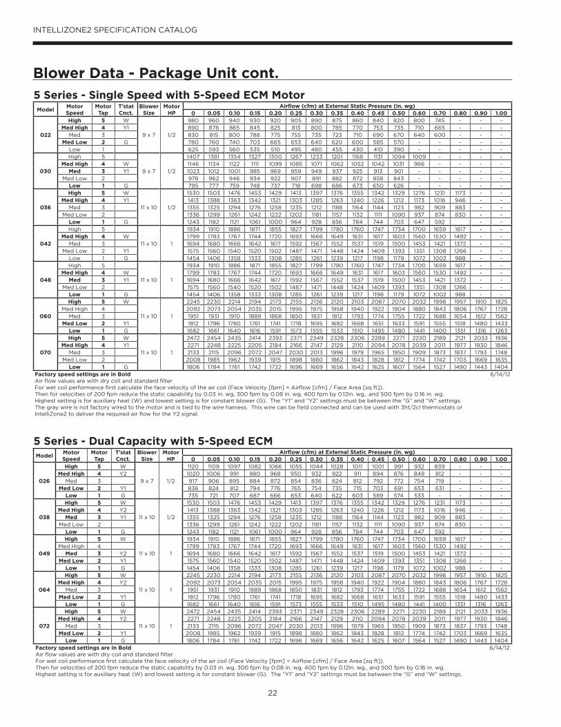
5 Series - Single Speed with 5-Speed ECM MotorModel
Motor Speed
Motor Tap
T’stat Cnct.
Blower Size
Motor HP
Airflow (cfm) at External Static Pressure (in. wg)0 0.05 0.10 0.15 0.20 0.25 0.30 0.35 0.40 0.45 0.50 0.60 0.70 0.80 0.90 1.00
022
High 5 W
9 x 7 1/2
980 960 940 930 920 905 890 875 860 840 820 800 745 - - -Med High 4 Y1 890 878 865 845 825 813 800 785 770 753 735 710 665 - - -
Med 3 830 815 800 788 775 755 735 723 710 690 670 640 600 - - -Med Low 2 G 780 760 740 703 665 653 640 620 600 585 570 - - - - -
Low 1 625 593 560 535 510 495 480 455 430 410 390 - - - - -
030
High 5
9 x 7 1/2
1407 1381 1354 1327 1300 1267 1233 1201 1168 1131 1094 1009 - - - -Med High 4 W 1146 1134 1122 1111 1099 1085 1071 1062 1052 1042 1031 966 - - - -
Med 3 Y1 1023 1012 1001 985 969 959 949 937 925 913 901 - - - - -Med Low 2 978 962 946 934 922 907 891 882 872 858 843 - - - - -
Low 1 G 795 777 759 748 737 718 698 686 673 650 626 - - - - -
036
High 5 W
11 x 10 1/2
1530 1503 1476 1453 1429 1413 1397 1376 1355 1342 1329 1276 1231 1173 - -Med High 4 Y1 1413 1388 1363 1342 1321 1303 1285 1263 1240 1226 1212 1173 1016 946 - -
Med 3 1355 1325 1294 1276 1258 1235 1212 1188 1164 1144 1123 982 909 883 - -Med Low 2 1336 1299 1261 1242 1222 1202 1181 1157 1132 1111 1090 937 874 830 - -
Low 1 G 1243 1182 1121 1061 1000 964 928 856 784 744 703 647 592 - -
042
High 5
11 x 10 1
1934 1910 1886 1871 1855 1827 1799 1780 1760 1747 1734 1700 1659 1617 - -Med High 4 W 1799 1783 1767 1744 1720 1693 1666 1649 1631 1617 1603 1560 1530 1492 - -
Med 3 1694 1680 1666 1642 1617 1592 1567 1552 1537 1519 1500 1453 1421 1372 - -Med Low 2 Y1 1575 1560 1540 1520 1502 1487 1471 1448 1424 1409 1393 1351 1308 1266 - -
Low 1 G 1454 1406 1358 1333 1308 1285 1261 1239 1217 1198 1179 1072 1002 988 - -
048
High 5
11 x 10 1
1934 1910 1886 1871 1855 1827 1799 1780 1760 1747 1734 1700 1659 1617 - -Med High 4 W 1799 1783 1767 1744 1720 1693 1666 1649 1631 1617 1603 1560 1530 1492 - -
Med 3 Y1 1694 1680 1666 1642 1617 1592 1567 1552 1537 1519 1500 1453 1421 1372 - -Med Low 2 1575 1560 1540 1520 1502 1487 1471 1448 1424 1409 1393 1351 1308 1266 - -
Low 1 G 1454 1406 1358 1333 1308 1285 1261 1239 1217 1198 1179 1072 1002 988 - -
060
High 5 W
11 x 10 1
2245 2230 2214 2194 2173 2155 2136 2120 2103 2087 2070 2032 1998 1957 1910 1825Med High 4 2092 2073 2054 2035 2015 1995 1975 1958 1940 1922 1904 1880 1843 1806 1767 1728
Med 3 1951 1931 1910 1889 1868 1850 1831 1812 1793 1774 1755 1722 1688 1654 1612 1562Med Low 2 Y1 1812 1796 1780 1761 1741 1718 1695 1682 1668 1651 1633 1591 1555 1518 1480 1433
Low 1 G 1682 1661 1640 1616 1591 1573 1555 1533 1510 1495 1480 1441 1400 1351 1316 1263
070
High 5 W
11 x 10 1
2472 2454 2435 2414 2393 2371 2349 2328 2306 2289 2271 2230 2189 2121 2033 1936Med High 4 Y1 2271 2248 2225 2205 2184 2166 2147 2129 2110 2094 2078 2039 2011 1977 1930 1846
Med 3 2133 2115 2096 2072 2047 2030 2013 1996 1979 1965 1950 1909 1873 1837 1793 1748Med Low 2 2008 1985 1962 1939 1915 1898 1880 1862 1843 1828 1812 1774 1742 1703 1669 1635
Low 1 G 1806 1784 1761 1742 1722 1696 1669 1656 1642 1625 1607 1564 1527 1490 1443 1404Factory speed settings are in BoldAir flow values are with dry coil and standard filterFor wet coil performance first calculate the face velocity of the air coil (Face Velocity [fpm] = Airflow [cfm] / Face Area [sq ft]). Then for velocities of 200 fpm reduce the static capability by 0.03 in. wg, 300 fpm by 0.08 in. wg, 400 fpm by 0.12in. wg., and 500 fpm by 0.16 in. wg.Highest setting is for auxiliary heat (W) and lowest setting is for constant blower (G). The “Y1” and “Y2” settings must be between the “G” and “W” settings.The gray wire is not factory wired to the motor and is tied to the wire harness. This wire can be field connected and can be used with 3ht/2cl thermostats or IntelliZone2 to deliver the required air flow for the Y2 signal.
6/14/12
5 Series - Dual Capacity with 5-Speed ECMModel
Motor Speed
Motor Tap
T’stat Cnct.
Blower Size
Motor HP
Airflow (cfm) at External Static Pressure (in. wg)0 0.05 0.10 0.15 0.20 0.25 0.30 0.35 0.40 0.45 0.50 0.60 0.70 0.80 0.90 1.00
026
High 5 W
9 x 7 1/2
1120 1109 1097 1082 1066 1055 1044 1028 1011 1001 991 932 839 - - -Med High 4 Y2 1020 1006 991 980 968 950 932 922 911 894 876 849 812 - - -
Med 3 917 906 895 884 872 854 836 824 812 792 772 754 719 - - -Med Low 2 Y1 836 824 812 794 776 765 754 735 715 703 691 653 631 - - -
Low 1 G 735 721 707 687 666 653 640 622 603 589 574 533 - - - -
038
High 5 W
11 x 10 1/2
1530 1503 1476 1453 1429 1413 1397 1376 1355 1342 1329 1276 1231 1173 - -Med High 4 Y2 1413 1388 1363 1342 1321 1303 1285 1263 1240 1226 1212 1173 1016 946 - -
Med 3 Y1 1355 1325 1294 1276 1258 1235 1212 1188 1164 1144 1123 982 909 883 - -Med Low 2 1336 1299 1261 1242 1222 1202 1181 1157 1132 1111 1090 937 874 830 - -
Low 1 G 1243 1182 1121 1061 1000 964 928 856 784 744 703 647 592 - -
049
High 5 W
11 x 10 1
1934 1910 1886 1871 1855 1827 1799 1780 1760 1747 1734 1700 1659 1617 - -Med High 4 1799 1783 1767 1744 1720 1693 1666 1649 1631 1617 1603 1560 1530 1492 - -
Med 3 Y2 1694 1680 1666 1642 1617 1592 1567 1552 1537 1519 1500 1453 1421 1372 - -Med Low 2 Y1 1575 1560 1540 1520 1502 1487 1471 1448 1424 1409 1393 1351 1308 1266 - -
Low 1 G 1454 1406 1358 1333 1308 1285 1261 1239 1217 1198 1179 1072 1002 988 - -
064
High 5 W
11 x 10 1
2245 2230 2214 2194 2173 2155 2136 2120 2103 2087 2070 2032 1998 1957 1910 1825Med High 4 Y2 2092 2073 2054 2035 2015 1995 1975 1958 1940 1922 1904 1880 1843 1806 1767 1728
Med 3 1951 1931 1910 1889 1868 1850 1831 1812 1793 1774 1755 1722 1688 1654 1612 1562Med Low 2 Y1 1812 1796 1780 1761 1741 1718 1695 1682 1668 1651 1633 1591 1555 1518 1480 1433
Low 1 G 1682 1661 1640 1616 1591 1573 1555 1533 1510 1495 1480 1441 1400 1351 1316 1263
072
High 5 W
11 x 10 1
2472 2454 2435 2414 2393 2371 2349 2328 2306 2289 2271 2230 2189 2121 2033 1936Med High 4 Y2 2271 2248 2225 2205 2184 2166 2147 2129 2110 2094 2078 2039 2011 1977 1930 1846
Med 3 2133 2115 2096 2072 2047 2030 2013 1996 1979 1965 1950 1909 1873 1837 1793 1748Med Low 2 Y1 2008 1985 1962 1939 1915 1898 1880 1862 1843 1828 1812 1774 1742 1703 1669 1635
Low 1 G 1806 1784 1761 1742 1722 1696 1669 1656 1642 1625 1607 1564 1527 1490 1443 1404Factory speed settings are in BoldAir flow values are with dry coil and standard filterFor wet coil performance first calculate the face velocity of the air coil (Face Velocity [fpm] = Airflow [cfm] / Face Area [sq ft]). Then for velocities of 200 fpm reduce the static capability by 0.03 in. wg, 300 fpm by 0.08 in. wg, 400 fpm by 0.12in. wg., and 500 fpm by 0.16 in. wg.Highest setting is for auxiliary heat (W) and lowest setting is for constant blower (G). The “Y1” and “Y2” settings must be between the “G” and “W” settings.
6/14/12

23
INTELLIZONE2 SPECIFICATION CATALOG
Wiring Schematic - Package Unit
IntelliZone2 System
75VA kit mounted in heat pump (PN ZTK240)
A+
R
C
B-
P11 –
Zon
e 1Ma
sterS
tat
A+
R
C
B-
P12 –
Zon
e 2
A+
R
C
B-
P13 –
Zon
e 3
A+
R
C
B-
P14 –
Zon
e 4
A+
R
C
B-
P15 –
Zon
e 5
A+
R
C
B-
P16 –
Zon
e 6
A+
R
C
B-
P3 –
Maste
rStat
Loca
l
C
B-
A+
R
P17 –
Hea
t Pum
p
NO NO
NCCom
Close
Zone 1 Dmpr
Open
P5
NO NO
NCCom
Close
Zone 2 Dmpr
Open
P6
NO NO
NCCom
Close
Zone 3 Dmpr
Open
P7
NO NO
NCCom
Close
Zone 4 Dmpr
Open
P8
NO NO
NCCom
Close
Zone 5 Dmpr
Open
P9
NO NO
NCCom
Close
Zone 6 Dmpr
Open
P10
LAS – Outdoor Air Sensor
P1
G G G
RR B Y
G G G
Zone 1
Zone 2
Heating Cooling
Zone 3
Zone 4 Zone 6
Zone 5
FanAlarm/Status
R
C
P18Damper Power
F1 DamperFuse
F2 Relay Board Fuse
IntelliZone2 Relay Board
DX+
R
C
DX-
Zone
1Ma
sterS
tatMasterStat
A+
R
C
B-
Zone
3 St
atOn32 1
Zone 3 code shown
A+
R
C
B-
Zone
5 St
atOn32 1
Zone 5 code shown
ZoneStat
SensorStat/SensorStat- Remote-Kit
MasterStat is always Zone 1
+
R
C
-
P7 -
Zone
Aurora AXB
Aurora ABC
Packaged Heat Pump
For Temporary Config or T-ShootZ2TK Kit
Damper Transformer
24V
Blue – 240V
Black - Com
Red – 208V
2-Wire Damper
1-Com
3-Close
2-Open
Drive Close/Spring Open
Drive Open/Drive Close
3-Wire Damper
Zone ID must be set for each Zone 2-6. ID can be confirmed on ZoneStat by pressing cancel button for 5 sec. ID shown on display. See Zone ID Codes.
Zone ID must be set for each Zone 2-6. ID cannot be confirmed on Zone Sensor Stat. See Zone ID Codes.
AID Tool
TSU02Optional Outdoor
Temp Sensor
Black/White
Yellow5A Fuse
3A Fuse
Light emitting diode - Green
Polarized connector
Low voltage wiring
Internal junction
Fuse
Legend
Relay Contacts-N.O., N.C.
G
132PScrew Terminal Strip
Com
Close
Open
On32 1
On32 1
On32 1
Zone 4 Zone 5Zone 3On
32 1
Zone 2On
32 1
Zone 6
Zone ID Codes
1) Zone ID must be set for each Zone 2-6. ID can be confirmed on ZoneStat by pressing cancel button for 5 sec. ID shown on display.2) Small screw driver can be used to set ID thru protective plastic skin!3) MasterStat always Zone 1. Zone ID not necessary4) TPCC32U01 zone is set thru touchscreen.
NOTES:
R
+
-
C
Harness Supplied withIntelliZone2 then wire
nut to stat wire
Wire nut
1-Com
2-Close
S1
S2 Optio
nal
Remo
te Se
nsor
Microprocessor and other
Components
TPCC32U01 DX+
R
C
DX-(Note 4)
S1
S2 Optio
nal
Remo
te Se
nsor
Note: Shorting a thermostat R/C input
will blow the ABC fuse not this fuse
NOTE: This drawing is for visual reference for wiring and
configuring a zone. Do not skip zones as shown here. Zones
MUST be wired in numerical sequence.

24
INTELLIZONE2 SPECIFICATION CATALOG
Damper Specifi cations
GeneralModel ZDRT3 and ZDCT3 are “3-wire” motorized
rectangular and circular dampers utilizing a 24VAC
actuator to power open and power close the damper in a
period of 95 seconds or less. The ZDRT2 and ZDCT2 are
“2-wire” motorized rectangular and circular dampers that
use a 2-wire actuator to power close and spring open the
damper. All dampers are constructed of heavy gauge G90
galvanized steel.
Damper/Actuator FeaturesThe IntelliZone2 system utilizes a “3-wire” power open/
power close damper actuator featuring:
• Brushless DC Motor (3-wire only)
• Adjustable open position (3-wire only)
• Manual damper release lever (3-wire only)
• No-stall brushless motor for long life
• Up to 2 in. W.G. differential pressure capability
• Magnetic Clutch (3-wire only)
• Quick replacement
• Low power draw
• Capable of 45 in. lbs. of torque minimum (45 in. lbs.
running or breakaway)
• 95 second opening (3-wire only)
• 95 second closing (3-wire only)
ZDR - Rectangular Damper Features• 18-gauge G90 galvanized sheet steel using the
“toggle lock” fastening system to increase corrosion
resistance
• Damper position indicator
• Available in sizes 8” H x 8” W through 14-inch
H x 30-inch W
• Air leakage less than 6% @ 2 in. W.G. (AMCA 500-75)
• Nylon bearing to prevent binding
ZDC - Circular Damper Features• 18-gauge G90 galvanized sheet steel using the
“toggle tab lock” fastening system to increase
corrosion resistance.
• Double beading to maintain roundness and rigidity.
• One straight and one crimp end.
• Nylon end bearing to prevent binding.
• Damper blades which close against a 1” foam seal for
air tightness.
• Damper position indicator.
• Available in 5-inch through 18-inch diameters.
• Air leakage less than 6% @ 2 in. W.G. (AMCA 500-75)
Model ZDR Rectangular Dampers
WIDTH IN INCHES 8" HIGH 10" HIGH 12" HIGH 14" HIGH
8 ZDR0808T2, T3 ZDR1008T2, T3 ZDR1208T2, T3 ZDR1408T2, T310 ZDR0810T2, T3 ZDR1010T2, T3 ZDR1210T2, T3 ZDR1410T2, T312 ZDR0812T2, T3 ZDR1012T2, T3 ZDR1212T2, T3 ZDR1412T2, T314 ZDR0814T2, T3 ZDR1014T2, T3 ZDR1214T2, T3 ZDR1414T2, T316 ZDR0816T2, T3 ZDR1016T2, T3 ZDR1216T2, T3 ZDR1416T2, T318 ZDR0818T2, T3 ZDR1018T2, T3 ZDR1218T2, T3 ZDR1418T2, T320 ZDR0820T2, T3 ZDR1020T2, T3 ZDR1220T2, T3 ZDR1420T2, T322 ZDR0822T2, T3 ZDR1022T2, T3 ZDR1222T2, T3 ZDR1422T2, T324 ZDR0824T2, T3 ZDR1024T2, T3 ZDR1224T2, T3 ZDR1424T2, T326 ZDR0826T2, T3 ZDR1026T2, T3 ZDR1226T2, T3 ZDR1426T2, T328 ZDR0828T2, T3 ZDR1028T2, T3 ZDR1228T2, T3 ZDR1428T2, T330 ZDR0830T2, T3 ZDR1030T2, T3 ZDR1230T2, T3 ZDR1430T2, T3
Model ZDRRectangular Damper
Model ZDC Circular Dampers Selection*
Diameter Part No. Length6" Round ZDC06T2, T3 9''8" Round ZDC08T2, T3 10''
10" Round ZDC10T2, T3 11''12" Round ZDC12T2, T3 12''14" Round ZDC14T2, T3 14''16" Round ZDC16T2, T3 16''18" Round ZDC18T2, T3 18''
Model ZDCCircular Damper
Damper Pressure Drop
400
200
300
500
600
700
800
900
1000
1100
1200
1300
1400
1500
1600
0.01
0.02
0.03
0.04
0.05
0.06
0.07
0.08
0.09
0.10
Velocity (fpm)
Pre
ssur
e D
rop
(in w
.c.)
Typical Circular
Typical Rectangular
0.00
NOTES: Actuators mounted on “H” dimension.*T2 indicates 2 wire (power close, spring open) dampers.T3 indicates 3 wire (power close, power open) dampers.
NOTES: *T2 indicates 2 wire (power close, spring open) dampers. T3 indicates 3 wire (power close, power open) dampers.

25
INTELLIZONE2 SPECIFICATION CATALOG
Zone SelectionSelecting zoning areas of a home or office is the first step required for successful IntelliZone2 setup. IntelliZone2 allows four independent zones of operation on dual capacity equipment and two independent zones of operation on single-speed equipment. Clearly, most homes and offices have more than four rooms. What must be decided is, “Given a maximum of four or two different zones of operation, which rooms in the house or office will be best suited under the control of the same sensor?” There are two basic ways to accomplish this:
1. Zoning by Use and Occupancy, or2. Zoning by Outside Exposure
Zoning by Use and OccupancyFor a typical residence, different rooms in the house are used or occupied at different times during the day. A typical single story home has three bedrooms, a kitchen, a living room , a dining area, bathroom(s), and a family room as shown below in Figure 1.
Never place more than one zone in a single room. Notethat the type of use in each room or group of similarly used rooms determines the assigned zone. Figure 1 illustrates a four zone example of zoning by use.
The kitchen, dining, living, family, and utility rooms areexcellent choices for a separate zone because they are commonly occupied during the same time of day and share common exposures. IntelliZone2 will provide more conditioned air to these areas when they are in use and less to other areas of the house when unoccupied.
It is doubtful that the living room, family room, kitchen, and bedrooms will all be occupied at the same time. For most of the year, the family room will be occupied at different times of the day than the living room and bedrooms.
The master suite and bedrooms should almost always be on separate zones than the main living areas because each area tends to be occupied at different times. Obviously, bedrooms are usually occupied during the night, not during the day when the living area of the house is occupied. With IntelliZone2, the bedrooms can be “setback” during the day and the main living areas “setback” at night. This allows the HVAC equipment to concentrate on the kitchen and living areas when occupied and on the bedrooms at night when the rest of the house may be unoccupied.
A feature in a residence which can dictate zoning is multiple stories or floors. In a two story structure, the upper and lower floors will have different heating or cooling demands. These differences can be attributed to heat migration (the tendency of heat to rise), types of use, occupancy, and the roof heat load.
Another example is a small doctor’s office. The zones to consider would be the waiting room, patient rooms, lab,and office areas. The waiting room is an excellent zonebecause the number of people will vary during the day; usually, an exterior door is opened frequently, and these rooms require large amounts of air for ventilation.
Patient rooms are another good choice for a zone; usually occupied by one to three people with tight requirements on temperature needed to ensure comfort. A lab or similar area could be a separate zone because of the different type of use as compared to the rest of the building.Other good commercial candidates might include small to medium size dentist offices, retail stores with employee lounges and offices, general commercial offices with computer rooms or conference rooms, car dealerships with show rooms, general offices, and parts rooms.
Zoning by Outside ExposureZoning by the exterior exposure considers the time of day when the peak cooling and heating loads occur. Zoning by exterior exposure should be considered when the following two conditions exist:
1. There are distinctly different rooms or areas along the south and west exposures, and the building has a large area of glass on those exposures. An example is a room where over half of the cooling load is due to transmission through the glass alone.
2. There are a relatively small number of people in the building and a small number of people occupying offices or spaces along the south or west sides of the building. In short, the heat gain due to people and the ventilation required for the occupants is small when compared to the overall cooling requirements for the building.
Zoning by exposure is not the normal method of zoning for most residences. The exceptions to this rule are rooms along the south or west which have large amounts of glass. Generally bedrooms on the southwest exposure require similar levels of heating or cooling because the time of use precludes heat gain from the sun as a major factor in occupant comfort. Exceptions include large windows or other features.
Using the zoning by exposure method in an office can be more difficult than in a home. If the predominant load in the building is people, the IntelliZone2 should follow the major occupancies in the building as determined by the occupants. If there are few people in the building, then zoning by exposure becomes prevalent since the heat load applied to the individual offices or rooms is dominated by the exposure and time of day. In all cases, judgement is required due to variations in climate, floor plan, type and time of use, glass areas, and glass orientation.
If still unsure which areas or offices to place in a particular zone, the best method is to use load calculations such as ASHRAE or another reliable method. Once this is done, compare the hours to peak load (both heating and cooling) and group offices together that have approximately the same time of day for the peak loads.

26
INTELLIZONE2 SPECIFICATION CATALOG
Zone Selection cont.
General Zone Selection Rules• Minimum of three branch runs per zone.• Zone together areas of like uses, but separate areas
based on differing uses• Avoid grouping rooms of different levels or floors into the
same zone.• Avoid grouping rooms with opposite sun or weather
exposures in the same zone.
NOTE: Ensure zone duct is designed to handle cfm required
Locating the ThermostatsThe thermostats must be located in the room or zone that
each controls. Locate a thermostat about five feet above
the floor. Do not locate a thermostat where it may be
exposed to direct sunlight, drafts or direct supply air. Do
not place a thermostat on an outside wall. Follow the same
guidelines that apply with standard thermostat installation.
If two or more rooms are on a single zone, locate the
thermostat in a hallway or area where it can sense the
return air from all rooms.
Sample Floor Plan with Four Zone Example
MasterBedroom
Bath
Bedroom
Bedroom
Kitchen
Living Room
UtilityRoom
Dining
Zone 2 Bedrooms
Zone 1 Main Living
Zone 3 Master Suite
Zone 4 Basement
IntelliZone2 Thermostat
NotShownFamily
Room
Bath
IntelliZone2 Design SoftwareThe IntelliZone2 Design software provides many
calculations required to properly design and configure
the IntelliZone2 system. This software is available free of
charge online at our secure site. Loads and equipment are
input to properly assess minimum zone duct design and
suggest zone %.
27
INTELLIZONE2 SPECIFICATION CATALOG
Special Zoning Applications
ResidentialUnfinished Basement
• Return air ducts are required to all zones.
• Careful design of ductwork, including return air, for future
finishing is crucial.
• Insulated basements, in general, require very little space
conditioning. However, the floor space can be substantial.
To provide adequate air movement, more air flow will be
required than the space conditioning load would indicate.
• In the North, an unfinished basement can be difficult
to raise above 65° F in the winter due to its large mass
of exposed concrete and typically minimal supply
and return ductwork. In the summer, damper leakage
occurring from cooling calls in other zones, along with
cool basement temperatures, can actually produce a
heating call in the basement. Use a “cooling only” mode
on the basement zone thermostat in the summer If this
becomes an issue.
• Continuous blower selection on the zone thermostat can
help circulate some of the cooler air to other zones in the
summer and help dehumidify the basement area.
Open Entry/Stairwell in a Multi-Story Home
• Large open areas between two floors allow a tremendous
volume of air to rise to the upper floor causing
overheating in the winter and undercooling in the
summer. Although running a continuous blower can help
recirculate the air between floors, a zone system will
provide the conditioning exactly to the zone that needs
it. Be careful that the system doesn't cool the upper level
while heating the lower level in the winter.
Garage, Unused or Unconditioned Zone
• Conditioned garages should be insulated and sealed
as tightly as possible to avoid excessive energy use.
Although a dedicated space conditioning unit installed
specifically for the garage is the best choice, this is not
always possible. If the garage zone is being conditioned
by the main system, typically only the supply air is
ducted. The thermostat setpoints, and thus the amount
of supply air, should be limited to avoid increasing air
infiltration to the home due to the negative pressure.
Main unit return air ducts are not allowed by most
building codes due to the chance of recirculating fumes
from the garage throughout the home.
• Unused zones can include guest bedrooms.
Unconditioned zones may include unfinished areas. Both
of these represent areas in which reduced setpoints
are desired to limit energy use. In these zones, a
continuous blower speed should not be selected. Due
to the common return system with other zones, the
setpoint should be no more than 4° F off from other
zone setpoints. If a larger setback is desired, a return
duct damper system should be installed in the zone to
more fully isolate the zone from the rest of the home.
In combination with return air dampers in scenarios
where large setbacks or unconditioned zones are desired
that zone must also be isolated from the conditioned
structure with doors, partitions, etc. to avoid air mixing.
Small Zone
• If a group of rooms is zoned but constitutes less than
15% of the total system load, the duct system needs to be
designed to handle the minimum 15% of the system air
flow (25% in dual and 50% in single-speed equipment).
For example, an ND049 system (1500 cfm max and 600
cfm minimum) would have a minimum design zone of
375 cfm (25% x 1500 cfm = 375 cfm). When this zone
calls, the unit will push 700 cfm through the ductwork
designed for 375 cfm. Although higher velocity will be
encountered here, the noise level and throw should not
be objectionable or even noticeable. This also eliminates
the need for a bypass damper. A minimum of three
branch runs should be employed in any zone to limit
the effects of one branch duct being blocked by shoes,
furniture, etc.
Sun Room
• A sunroom can present a tremendous cooling load and
will likely require a higher cooling setpoint. Such rooms
represent areas in which reduced setpoints would be
desired to limit energy use. In these zones, continuous
blower should not be selected and, due to the common
return system with other zones, the setpoint should be
no more than 4° F off other zone setpoints. If a >4° F
setback is desired, a return duct damper system should
be installed in the zone to more fully isolate it from the
rest of the home.
CommercialConference Room/Office
• Frequently, conference room(s) and office(s) are grouped
together on the same zone due to the direction of
exposure. However, when a closed-door conference is
held with 12 people, it frequently becomes uncomfortable
for either the conference room occupants or one of the
office occupants (due to the tremendous difference in
loads present within the zone). Here, zoning can solve
the problem easily by providing the exact cooling where
and when needed.

28
INTELLIZONE2 SPECIFICATION CATALOG
Peak Heating and Cooling Demands
Cooling-Dominated StructuresIn cooling-dominated structures such as commercial
buildings and southern residential homes (where electric
heat is rarely needed as an auxiliary heat source), up to
five load calculations need to be performed. Commercial
hourly peak load calculations on all of the four zones
under control of the IntelliZone2 System are required. This
information sizes the supply air ductwork and the zone
damper properly. The fifth load is the entire building (all four
zones). Why perform this step? Because the different zones
have different times of day when they need peak cooling or
heating. The actual peak cooling or heating load is usually
less than the sum of the peak loads for the four zones.
The load calculation for the entire structure is used to size
the HVAC equipment only. Ductwork branches and zone
dampers are sized using the peak zone conditions for each
particular zone. The difference between the sum of the
peak loads for the individual zones and the peak load for
the entire building is called “diversity”.
Diversity is a measurement of the effective cooling or
heating capacity added to the system due to zoning. The
physical heating or cooling capacity is not increased,
but because it is more effective, HVAC equipment can
be sized smaller using zoning diversity. This represents
the first cost savings of the IntelliZone2 Comfort Zoning
System. Secondary savings are attributed to the lower
operating costs.
Many popular software packages or HVAC residential
loads now calculate peak zone loads; check your software
package for its capability.
Heating-Dominated StructuresIn heating-dominated structures, such as northern
residential homes (where units are generally sized with
a small amount of electric heat installed as an auxiliary
heat source), diversity may be present in cooling; however,
the unit size is dictated by the heating load and diversity
is rarely present. In this application, a simple room-by-
room or zone-by-zone analysis can be performed with the
resultant sum of the rooms or zones taken as the whole
house load. The table below lists the four zone loads of this
example home.
NOTE: Dual Capacity 5 Series has a 70% low capacity
output, therefore minimum cfm required per zone is 40% of
nominal cfm.
Example Four Zone Load Summary
Htg Btu/h
Htgcfm
Total Clg
SensClg
Clgcfm
Maxcfm
Adjusted100% cfm
Min cfmReq’d.
Designcfm
# ofBranch
Actualcfm %
ActualLoad %
ZoneDIP %
Zone 1 Main Living
Kitchen 2259 73 3128 2400 145 145 118 1
Family 4264 138 6660 5128 311 311 252 2
Utility 3002 97 1614 1243 75 97 78 1
Living/Dining 6351 205 7158 5511 334 334 271 3
Total 15876 512 18560 14282 866 887 718 600 718 29% 34% 45%
Zone 2 Bedrooms
Bdrm 1 3224 104 1939 1752 106 106 240 2
Main Bath 892 29 284 407 25 65 147 1
Bdrm 2 2708 87 1692 1550 94 94 213 1
Total 6824 220 3915 3709 225 265 215 600 600 24% 15% 45%
Zone 3 Master Suite
Mstr Bdrm 2806 91 2294 1766 107 107 351 2
Mstr Bath 2350 76 1504 1158 70 76 249 1
Total 5156 166 3798 2924 177 183 148 600 600 24% 11% 45%
Zone 4 Basement
Total 19123 617 5007 3967 240 517 419 600 600 4 24% 41% 45%
Total Zones 46979 1515 31280 24882 1508 1852 1500 2518
Total House 46290 @ 70°F 32822 @ 20°F 123% 100% 168%
Unit DataNom Hi cfm Min Lo cfm 40% Nom cfm
Model
ND*049 1500 1350 600
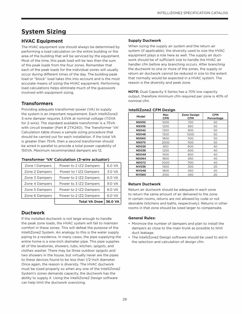
29
INTELLIZONE2 SPECIFICATION CATALOG
System Sizing
HVAC EquipmentThe HVAC equipment size should always be determined by
performing a load calculation on the entire building or the
area of the building that will be serviced by the equipment.
Most of the time, this peak load will be less than the sum
of the peak loads from the four zones. Remember that
each of the peak loads for the individual zones will usually
occur during different times of the day. The building peak
load or “block” load takes this into account and is the most
accurate means of sizing the HVAC equipment. Performing
load calculations helps eliminate much of the guesswork
involved with equipment sizing.
TransformersProviding adequate transformer power (VA) to supply
the system is an important requirement. Each IntelliZone2
3-wire damper requires 3.0VA at nominal voltage (7.0VA
for 2-wire). The standard available transformer is a 75VA
with circuit breaker (Part # ZTK240). The Transformer 'VA'
Calculation table shows a sample sizing procedure that
should be carried out for each installation. If the total VA
is greater than 75VA, then a second transformer should
be wired in parallel to provide a total power capability of
150VA. Maximum recommended dampers are 12.
Transformer ‘VA’ Calculation (3-wire actuator)
Zone 1 Dampers Power to 2 IZ2 Dampers 6.0 VA
Zone 2 Dampers Power to 1 IZ2 Dampers 3.0 VA
Zone 3 Dampers Power to 2 IZ2 Dampers 6.0 VA
Zone 4 Dampers Power to 3 IZ2 Dampers 9.0 VA
Zone 5 Dampers Power to 2 IZ2 Dampers 6.0 VA
Zone 6 Dampers Power to 2 IZ2 Dampers 6.0 VA
Total VA Draw 36.0 VA
Ductwork If the installed ductwork is not large enough to handle
the peak zone loads, the HVAC system will fail to maintain
comfort in these zones. This will defeat the purpose of the
IntelliZone2 System. An analogy to this is the water supply
piping to a residence. In many cases, the pipe supplying the
entire home is a one-inch diameter pipe. This pipe supplies
all of the lavatories, showers, tubs, kitchen, spigots, and
clothes washer. There may be three outdoor spigots and
two showers in the house, but virtually never are the pipes
to these devices found to be less than 1/2-inch diameter.
Once again, the reason is diversity. The HVAC ductwork
must be sized properly so when any one of the IntelliZone2
System's zones demands capacity, the ductwork has the
ability to supply it. Using the IntelliZone2 Design software
can help limit the ductwork oversizing.
Supply Ductwork
When sizing the supply air system and the return air
system (if applicable), the diversity used to size the HVAC
equipment plays a role here as well. The supply air duct-
work should be of sufficient size to handle the HVAC air
handler cfm before any branching occurs. After branching
the ductwork to one or more of the zones, the supply or
return air ductwork cannot be reduced in size to the extent
that normally would be expected in a HVAC system. The
reason is the diversity and peak zone.
NOTE: Dual Capacity 5 Series has a 70% low capacity
output, therefore minimum cfm required per zone is 40% of
nominal cfm.
IntelliZone2 CFM Design
ModelMaxCFM
Zone Design CFM
CFMPercentage
NS030 1000 700 50
NS036 1200 850 50
NS042 1300 900 50
NS048 1500 1000 50
NS060 1800 1100 50
NS070 2000 1100 50
ND026 800 600 40
ND038 1200 600 40
ND049 1500 800 40
ND064 1800 950 40
ND072 2000 1100 40
NV036 1500 300 20
NV048 1800 450 20
NV060 2100 450 20
Return Ductwork
Return air ductwork should be adequate in each zone
to return the same amount of air delivered to the zone.
In certain rooms, returns are not allowed by code or not
desirable (kitchens and baths, respectively). Returns in other
rooms in that zone should be sized larger to compensate.
General Rules:
• Minimize the number of dampers and plan to install the
dampers as close to the main trunk as possible to limit
duct leakage.
• The IntelliZone2 Design software should be used to aid in
the selection and calculation of design cfm.

30
INTELLIZONE2 SPECIFICATION CATALOG
System Sizing cont.Four Zone Ductwork Example (Delivery cfm)
MasterBedroom
Bath
Bath
Bedroom
Bedroom
Kitchen
Living Room
FamilyRoom
UtilityRoom
Dining ToBasement
DamperSupply Ductwork
78 90 118 249 175
120
120
2139090
147600
126
126175
General Installation Guidelines General rules to follow when installing a zone system:
CAUTION: When installing the IntelliZone2 in a structure with fossil fuel (oil, gas, propane) appliances, it is important that both supply and return dampers are used in each zone to avoid potential backdrafting of fossil-fueled appliances.
• Up to six zones with variable speed (four with dual
capacity and two with single-speed units)
• All dampers should be located as close to the main trunk
as possible to limit the amount of pressurized trunkline
and thus limit air leakage.
• No less than three branch runs in a zone to prevent a
single branch obstruction (curtains or clothes etc.) from
affecting unit airfow.
• Insulate and seal around rectangular dampers to
prevent leakage.
• All dampers must be wired with 18-gauge wire. (Note:
Crimp connections should never be used on solid
conductor wire.)
• Ensure that the transformer can handle the power
requirements of the system.
• No more than three dampers per zone.
• Ductboard-mounted dampers should be supported
within six inches of the damper due to the weight and
stress on the ductboard.

31
INTELLIZONE2 SPECIFICATION CATALOG
IntelliZone2 with SAH Air Handler

32
INTELLIZONE2 SPECIFICATION CATALOG
IntelliZone2 Split OperationFor the split system to be compatible with IntelliZone2 there must be either an AXB in the compressor section or an AHB in the SAH Air Handler. As always an ABC board must be in the comressor section as well.
Upon a call (or calls) from the zones, the IntelliZone2 “weighs” each zone based upon two components: 1) the level of call (Y1, Y2, Y3) coming from the zone; and 2) the size of the zone (zone % selected). This gives a very accurate picture of not only overall heating or cooling requirements (as in other control methods), but also how much heating or cooling is really required for each separate zone.
This, in turn, defines how much compressor (1st or 2nd stage), blower and auxiliary heat should be engaged for each particular situation. The result is a system that utilizes lower compressor speed more often for improved comfort and energy savings, while relying upon auxiliary heat less often for more energy savings than non-zoned systems.
The variable speed ECM motor allows 6 air flow levels with IntelliZone2 while the 5 Speed ECM will allow 4 air flow levels. Althought the 5 speed ECM works with the IntelliZone2 the additional available air flow levels and air flow adjustability make the variable speed ECM the better option for zoning.
Heating, Unit 1st stage (Single/Dual Capacity Compressor and Variable Speed ECM)
Operation as stated above with separate zone call levels of YI, Y2, and W being translated into unit call 1st stage (Y1). Blower speed will be the ‘L’ setting of the ECM which is set up at the heat pump control.
Heating, Unit 1st stage (Single/Dual Capacity Compressor and 5-Speed ECM)
Operation as stated above with separate zone call levels of YI, Y2, and W being translated into unit call 1st stage (Y1). Blower speed will be the ‘Y1’ setting of the 5-Speed ECM which is set at the motor.
Heating, Unit 2nd stage(Single/Dual Capacity Compressor and Variable Speed ECM)
Operation as stated above with separate zone call levels of YI, Y2, and W being translated into unit call 2nd stage (Y1, Y2). Blower speed will be the ‘H’ setting of the ECM which
is set up at the heat pump control.
Heating, Unit 2nd stage(Single/Dual Capacity Compressor and 5-Speed ECM)
Operation as stated above with separate zone call levels of YI, Y2, and W being translated into unit call 2nd stage (Y1, Y2). Blower speed will be the ‘Y2’ setting of the 5-Speed
ECM which is set at the motor.
Heating, Unit 3rd Stage(Single/Dual Capacity Compressor and Variable Speed ECM)
Operation as stated above with separate zone call levels of YI, Y2, and W being translated into unit call 3rd stage (Y1, Y2, W). Blower speed will be the ‘H’ (Premier control) or ‘Aux’ (ABC control) setting of the ECM which is set up at
the heat pump control.
Heating, Unit 3rd Stage(Single/Dual Capacity Compressor and 5-Speed ECM)
Operation as stated above with separate zone call levels of YI, Y2, and W being translated into unit call 3rd stage (Y1, Y2, W). Blower speed will be the ‘W’ setting of the 5-Speed
ECM which is set at the motor.
Cooling, Unit 1st stage(Single/Dual Capacity Compressor and Variable Speed ECM)
Operation as stated above with separate zone call levels of YI, Y2, and O being translated into unit call 1st stage (Y1, O). Blower speed will be the ‘L’ setting of the ECM which is set up at the heat pump control.
Cooling, Unit 1st stage(Single/Dual Capacity Compressor and 5-Speed ECM)
Operation as stated above with separate zone call levels of YI, Y2, and O being translated into unit call 1st stage (Y1, O). Blower speed will be the ‘Y1’ setting of the 5-Speed ECM which is set at the motor.
Cooling, Unit 2nd stage(Single/Dual Capacity Compressor and Variable Speed ECM)
Operation as stated above with separate zone call levels of YI, Y2, and O being translated into unit call 2nd stage (Y1, Y2, O). Blower speed will be the ‘H’ setting of the ECM which is set up at the heat pump control.
Cooling, Unit 2nd stage(Single/Dual Capacity Compressor and 5-Speed ECM)
Operation as stated above with separate zone call levels of YI, Y2, and O being translated into unit call 2nd stage (Y1, Y2, O). Blower speed will be the ‘Y2’ setting of the 5-Speed ECM which is set at the motor.
Dehumidification (Variable Speed ECM)If dehumidification is desired it is set via the AID Tool on the ABC control by selecting -5% to -15% in the cooling airflow setup or by setting SW2-4 to OFF on the Premier control (85% of normal CFM). Not available with 5-Speed ECM
Description of Operation - Split System
33
INTELLIZONE2 SPECIFICATION CATALOG
Description of Operation cont.Emergency HeatEmergency heat mode may be engaged by selecting at the MasterStat. All zone thermostat fault LED's begin to flash two quick flashes, followed by a pause, indicating that emergency heat mode has been activated. The temperature of the structure will be controlled by the zone 1 MasterStat while other zones are ignored. When a demand for heat occurs at the MasterStat all zone dampers are opened and emergency heat is energized. Emergency heat will continue to operate until the MasterStat demand is satisfied.
Emergency heat mode may be exited by selecting OFF (or one of the other mode selections) at the MasterStat, as well as all zone thermostat fault LED's stop flashing, indicating emergency heat mode has been deactivated and normal IntelliZone2 operation may resume.
Continuous BlowerAll dampers are open and the unit's blower will be operated while heating or cooling is suspended for any zone(s) selected for continuous blower operation at the zone thermostat. Upon any heating or cooling call to the unit, all continuous blower operation ceases.
Lockout Mode(Single/Dual Speed Compressor)
During the unit lockout mode, the appropriate Fault code will be communicated to the MasterStat and the blower will operate continuously. If the collective zones translate into a > 24% heating call, emergency heat operation will
occur and all zone dampers will open. Blower speed will be
highest selected speed setting at the heat pump.
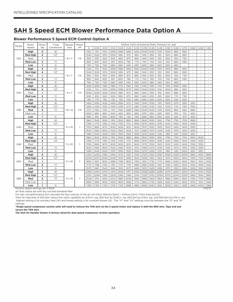
34
INTELLIZONE2 SPECIFICATION CATALOG
SAH 5 Speed ECM Blower Performance Data Option A
ModelMotor Speed
Motor Tap
T’stat Connection
Blower Size
Motor HP
Airflow (cfm) at External Static Pressure (in. wg)
0 0.05 0.10 0.15 0.20 0.25 0.30 0.35 0.40 0.45 0.50 0.60 0.70 0.80 0.90 1.00
022
High 5 W
9 x 7 1/2
1130 1115 1100 1090 1080 1065 1050 1040 1030 1015 1000 980 950 - - -
Med High 4 Y2* 1040 1025 1010 1000 990 975 960 945 930 915 900 880 850 - - -
Med 3 950 935 920 905 890 875 860 845 830 815 800 760 730 - - -
Med Low 2 Y1 860 845 830 815 800 785 770 755 740 720 700 660 590 - - -
Low 1 G 740 720 700 680 660 645 630 605 580 540 500 460 - - - -
026
High 5 W
9 x 7 1/2
1130 1115 1100 1090 1080 1065 1050 1040 1030 1015 1000 980 950 - - -
Med High 4 Y2* 1040 1025 1010 1000 990 975 960 945 930 915 900 880 850 - - -
Med 3 950 935 920 905 890 875 860 845 830 815 800 760 730 - - -
Med Low 2 Y1 860 845 830 815 800 785 770 755 740 720 700 660 590 - - -
Low 1 G 740 720 700 680 660 645 630 605 580 540 500 460 - - - -
030
High 5 W
9 x 7 1/2
1220 1205 1190 1180 1170 1160 1150 1140 1130 1115 1100 1050 930 - - -
Med High 4 Y2* 1130 1115 1100 1090 1080 1070 1060 1045 1030 1015 1000 980 950 - - -
Med 3 1040 1030 1020 1005 990 975 960 945 930 915 900 890 850 - - -
Med Low 2 Y1 950 935 920 905 890 875 860 845 830 815 800 770 730 - - -
Low 1 G 790 770 750 735 720 700 680 660 640 620 600 530 500 - - -
036
High 5 W
10 x 8 1/2
1450 1435 1420 1405 1390 1375 1360 1345 1330 1315 1300 1270 1250 1210 - -
Med High 4 Y2* 1350 1335 1320 1305 1290 1275 1260 1245 1230 1215 1200 1170 1140 1100 - -
Med 3 Y1 1170 1150 1130 1115 1100 1080 1060 1045 1030 1015 1000 960 920 880 - -
Med Low 2 1000 980 960 940 920 905 890 870 850 825 800 760 710 650 - -
Low 1 G 990 915 840 800 760 730 700 680 660 630 600 520 470 430 - -
042
High 5 W
11 x 10 1
1960 1945 1930 1915 1900 1880 1860 1845 1830 1810 1790 1750 1700 1660 - -
Med High 4 Y2* 1790 1775 1760 1745 1730 1710 1690 1670 1650 1535 1420 1560 1500 1450 - -
Med 3 1700 1685 1670 1650 1630 1615 1600 1575 1550 1525 1500 1450 1400 1350 - -
Med Low 2 Y1 1630 1560 1600 1520 1560 1535 1510 1490 1470 1445 1420 1370 1300 1250 - -
Low 1 G 1490 1445 1400 1375 1350 1325 1300 1270 1240 1210 1180 1120 1000 930 - -
048
High 5 W
11 x 10 1
1960 1945 1930 1915 1900 1880 1860 1845 1830 1810 1790 1750 1700 1660 1600 -
Med High 4 Y2* 1790 1775 1760 1745 1730 1710 1690 1670 1650 1535 1420 1560 1500 1450 1450 -
Med 3 1700 1685 1670 1650 1630 1615 1600 1575 1550 1525 1500 1450 1400 1350 1350
Med Low 2 Y1 1630 1560 1600 1520 1560 1535 1510 1490 1470 1445 1420 1370 1300 1250 1250 -
Low 1 G 1490 1445 1400 1375 1350 1325 1300 1270 1240 1210 1180 1120 1000 930 930 -
060
High 5 W
11 x 10 1
2210 2230 2190 2194 2170 2155 2130 2120 2100 2087 2060 2020 2000 1960 1920 1890
Med High 4 Y2* 2030 2073 2000 2035 1970 1995 1940 1958 1910 1922 1870 1840 1800 1760 1720 1680
Med 3 1850 1931 1820 1889 1790 1850 1760 1812 1730 1774 1680 1640 1600 1560 1510 1450
Med Low 2 Y1 1770 1796 1740 1761 1710 1718 1680 1682 1630 1651 1590 1560 1500 1450 1400 1340
Low 1 G 1570 1661 1540 1616 1510 1573 1460 1533 1420 1495 1370 1320 1250 1200 1100 1020
066
High 5 W
11 x 10 1
2390 2454 2370 2414 2340 2371 2320 2328 2290 2289 2270 2230 2200 2170 2140 2100
Med High 4 Y2* 2210 2248 2180 2205 2160 2166 2140 2129 2100 2094 2070 2040 2000 1960 1940 1890
Med 3 Y1 2030 2115 2010 2072 1980 2030 1950 1996 1900 1965 1880 1840 1800 1760 1720 1680
Med Low 2 1860 1985 1830 1939 1800 1898 1770 1862 1730 1828 1690 1640 1600 1570 1510 1460
Low 1 G 1780 1784 1750 1742 1720 1696 1680 1656 1640 1625 1600 1550 1500 1460 1400 1380Factory speed settings are in BoldAir flow values are with dry coil and standard filterFor wet coil performance first calculate the face velocity of the air coil (Face Velocity [fpm] = Airflow [cfm] / Face Area [sq ft]). Then for velocities of 200 fpm reduce the static capability by 0.03 in. wg, 300 fpm by 0.08 in. wg, 400 fpm by 0.12in. wg., and 500 fpm by 0.16 in. wg. Highest setting is for auxiliary heat (W) and lowest setting is for constant blower (G). The “Y1” and “Y2” settings must be between the “G” and “W” settings.*Single speed compressor section units will need to remove the TAN wire on the 5 speed motor and replace it with the RED wire. Tape end and secure the TAN wire.The SAH Air Handler blower is factory wired for dual speed compressor section operation.
1/10/17
Blower Performance 5 Speed ECM Control Option A

35
INTELLIZONE2 SPECIFICATION CATALOG
SAH 5 Speed ECM Blower Performance Data Option A cont.5-Speed ECM Constant Torque MotorsThe 5-Speed ECM is a 'Constant Torque' ECM motor and
delivers air flow similar to a PSC but operates as efficiently
as an ECM Motor. Because it's an ECM Motor, the 5-Speed
ECM can ramp slowly up to down like the ECM motor. There
are 5 possible speed taps available on the 5-Speed ECM
motor with #1 being the lowest airflow and #5 being the
highest airflow. These speed selections are preset at the
time of manufacture and are easily changed in the field if
necessary.
If more than one tap are energized at the same time, built
in logic gives precedence to the highest tap number and
allows air flow to change with G, Y1, Y2 and W signals. Each
of those 5 speeds has a specific 'Torque' value programmed
into the motor for each speed selection. As static pressure
increases, airflow decreases resulting in less torque on the
rotor. The motor responds only to changes in torque and
adjusts its speed accordingly.
The 5-Speed ECM motor is powered by line voltage but the
motor speed is energized by 24 VAC.
5-Speed ECM Benefits:
• High Efficiency
• Soft Start
• 5 speeds with up to 4 speeds on-line
• Built-in logic allows air flow to change with G, Y1, Y2
and W signals
• Super efficient low airflow continuous blower setting.
Setting Blower Speed - 5-Speed ECM5-Speed ECM blower motors have five (5) speeds of which
three (3) are selectable on single speed and four (4) are
selectable on dual capacity.
Caution: Disconnect all power before performing this operation.
L G NC
High VoltageConnections
3/16 in.
1 2 3 4 5G - Blue
Y1 - Red
AUX - Gray
C - Black
L - OrangeG - Green
N - Brown
Low VoltageConnections 1/4 in.
L G NC
1 2 3 4 5 AUX - GrayG - Blue
Y1 - Red Y2 - Tan
C - Black
L - OrangeG - Green
N - Brown
High VoltageConnections
3/16 in.
Low VoltageConnections 1/4 in.
5-Speed ECM Motor Connections - Single Speed Splits
5-Speed ECM Motor Connections - Dual Capacity Splits

36
INTELLIZONE2 SPECIFICATION CATALOG
SAH Blower Performance Data Option C
5 Series - Single Speed Split with SAH Air Handler
Split Model
SAH Model
Motor HP MAX ESPVariable Speed ECM Settings with IntelliZone2 Blower Level Percentages
1 2 3 4 5 6 7 8 9 10 11 12
036 036 1/2 0.50 550 650 700800
G850 900 950
1050 L 55%
1100 70%-85%
1200 H 100%
1300 Aux
042 042 1 0.75 650 750 800900
G1000
1150 L 55%
1200 70%
1300 85%
1400 H 100%
1500 16001700 Aux
048 048 1 0.75 650 750 800 9001000
G1150 1200
1300 L 55%
1400 70%
1500 85%
1600 H 100%
1700 Aux
060 060 1 0.75 9501100
G1200 1350
1500 L 55%
1650 70%
17001800 85%
2000 H 100%
2100 Aux
2200
070 066 1 0.75 950 1100
G1200 1350 1500
1650 L 55%
1700 70%
18002000 85%
2100 H 100%
2200 Aux
Blower level percentages are shown with factory recommended blower speed settingsL and H settings MUST be located within boldface CFM range“Aux” is factory setting for auxiliary heat and must be equal to or above the “H” setting as well as at least the minimum required for the auxiliary heat package“G” may be located anywhere within the airflow tableCFM is controlled within 5% up to the maximum ESPMax ESP includes allowance for wet coil and standard filterSAH Air Handler with control option “C”
3/10/2017
5 Series - Dual Capacity Split with SAH Air Handler
Split Model
SAH Model
Motor HP MAX ESPVariable Speed ECM Settings with IntelliZone2 Blower Level Percentages
1 2 3 4 5 6 7 8 9 10 11 12
026 026 1/2 0.50400
G500
600 L 55%
700 70%
800 85%
900 H 100%
1000 11001200 Aux
038 036 1/2 0.50 550 650700
G800
850 L 55%
900950 70%
1050 85%
11001200
H 100%1300 Aux
049 048 1 0.75 650 750800
G900
1000 L 55%
11501200 70%
13001400 85%
15001600
H 100%1700 Aux
064 060 1 0.75950 G
1100 L 55%
12001350 70%
1500 16501700 85%
18002000
H 100%2100 Aux
2200
072 066 1 0.75 9501100
G1200
1350 L 55%
15001650 70%
17001800 85%
20002100
H 100%2200 Aux
Blower level percentages are shown with factory recommended blower speed settingsL and H settings MUST be located within boldface CFM range“Aux” is factory setting for auxiliary heat and must be equal to or above the “H” setting as well as at least the minimum required for the auxiliary heat package“G” may be located anywhere within the airflow tableCFM is controlled within 5% up to the maximum ESPMax ESP includes allowance for wet coil and standard filterSAH Air Handler with control option “C”
3/10/2017

37
INTELLIZONE2 SPECIFICATION CATALOG
Blower Performance Data Option C cont.
ECM Speed Info
1▶ 2 ◀ G 3 4 5 6 7 8 9 10 11 12
Option ◀▶ Enter ◙
ECM Speed Info
1 2 G▶ 3 ◀ Lo 4 5 6 7 8 9 10 11 12
Option ◀▶ Enter ◙
ECM Speed Info
1 2 G 3 Lo 4 5▶ 6 ◀ Hi 7 8 9 10 11 12
Option ◀▶ Enter ◙
ECM Speed Info
1 2 G 3 Lo 4 5 6 Hi 7 8 9▶10 ◀ Aux 11 12
Option ◀▶ Enter ◙
ECM Speed Info
Blower Only Speed 3Lo Compressor 6Hi Compressor 9Aux Heat 10
Want To Change?
YesOption ◀▶
NoEnter ◙
Cooling Airflow Setup
--- ECM Only ---The airflow will be
adjusted by the chosenamount in cooling mode.
Adjustment:-15%
Want To Change?
Yes Option ◀▶
No Enter ◙
Cooling Airflow Setup
--- ECM Only ---The airflow will be
adjusted by the chosenamount in cooling mode.
Adjustment:-15%
Change ▼▲ Enter ◙
Setting Blower Speed - Variable Speed ECM The ABC board’s Yellow Config LED will flash the current
ECM blower speed selections for “G”, low, and high
continuously with a short pause in between. The speeds
can also be confirmed with the AID Tool under the Setup/
ECM Setup screen. The Aux will not be flashed but can be
viewed in the AID Tool. The ECM blower motor speeds can
be field adjusted with or without using an AID Tool.
ECM Setup without an AID Tool
The blower speeds for “G”, Low (Y1), High (Y2), and Aux
can be adjusted directly at the Aurora ABC board which
utilizes the push button (SW1) on the ABC board. This
procedure is outlined in the ECM Configuration Mode
portion of the Aurora ‘Base’ Control System section. The
Aux cannot be set manually without an AID Tool.
ECM Setup with an AID Tool
A much easier method utilizes the AID Tool to change
the airflow using the procedure below. First navigate to
the Setup screen and then select ECM Setup. This screen
displays the current ECM settings. It allows the technician
to enter the setup screens to change the ECM settings.
Change the highlighted item using the ◀ and ▶ buttons and
then press the ◙ button to select the item.
Selecting YES will enter ECM
speed setup, while selecting NO
will return to the previous screen.
ECM Speed Setup - These screens allow the technician to
select the “G”, low, high, and auxiliary heat blower speed for
the ECM blower motor. Change the highlighted item using
the ▲ and ▼ buttons. Press the ◙ button to select the speed.
After the auxiliary heat speed setting is selected the AID
Tool will automatically transfer back to the ECM Setup screen.
Cooling Airflow Setup - These screens allow the technician
to select -15%, -10%, -5%, None or +5%. Change the
adjustment percentage using the ▲ and ▼ buttons. Press
the ◙ button to save the change.

38
INTELLIZONE2 SPECIFICATION CATALOG
Wiring SchematicSplit Units
A+
R
C
B-
P11 –
Zon
e 1Ma
sterS
tat
A+
R
C
B-
P12 –
Zon
e 2
A+
R
C
B-
P13 –
Zon
e 3
A+
R
C
B-
P14 –
Zon
e 4
A+
R
C
B-
P15 –
Zon
e 5
A+
R
C
B-
P16 –
Zon
e 6
A+
R
C
B-
P3 –
Maste
rStat
Loca
l
C
B-
A+
R
P17 –
Hea
t Pum
p
NO NO
NCCom
Close
Zone 1 Dmpr
Open
P5
NO NO
NCCom
Close
Zone 2 Dmpr
Open
P6
NO NO
NCCom
Close
Zone 3 Dmpr
Open
P7
NO NO
NCCom
Close
Zone 4 Dmpr
Open
P8
NO NO
NCCom
Close
Zone 5 Dmpr
Open
P9
NO NO
NCCom
Close
Zone 6 Dmpr
Open
P10
LAS – Outdoor Air Sensor
P1
G G G
RR B Y
G G G
Zone 1
Zone 2
Heating Cooling
Zone 3
Zone 4 Zone 6
Zone 5
FanAlarm/Status
R
C
P18Damper Power
F1 DamperFuse
F2 Relay Board Fuse
IntelliZone2 Relay Board
DX+
R
C
DX-
Zone
1Ma
sterS
tatMasterStat
A+
R
C
B-
Zone
3 St
atOn32 1
Zone 3 code shown
A+
R
C
B-
Zone
5 St
atOn32 1
Zone 5 code shown
ZoneStat
SensorStat/SensorStat- Remote-Kit
MasterStat is always Zone 1
+
R
C
-
P7 -
Zone
Aurora AXB or Air Handler AHB
Aurora ABC
Split Heat Pump
For Temporary Config or T-ShootZ2TK Kit
Damper Transformer
24V
Blue – 240V
Black - Com
Red – 208V
2-Wire Damper
1-Com
3-Close
2-Open
Drive Close/Spring Open
Drive Open/Drive Close
3-Wire Damper
Zone ID must be set for each Zone 2-6. ID can be confirmed on ZoneStat by pressing cancel button for 5 sec. ID shown on display. See Zone ID Codes.
Zone ID must be set for each Zone 2-6. ID cannot be confirmed on Zone Sensor Stat. See Zone ID Codes.
AID Tool
TSU02Optional Outdoor
Temp Sensor
Black/White
Yellow5A Fuse
3A Fuse
Light emitting diode - Green
Polarized connector
Low voltage wiring
Internal junction
Fuse
Legend
Relay Contacts-N.O., N.C.
G
132PScrew Terminal Strip
Com
Close
Open
On32 1
On32 1
On32 1
Zone 4 Zone 5Zone 3On
32 1
Zone 2On
32 1
Zone 6
Zone ID Codes
1) Zone ID must be set for each Zone 2-6. ID can be confirmed on ZoneStat by pressing cancel button for 5 sec. ID shown on display.2) Small screw driver can be used to set ID thru protective plastic skin!3) MasterStat always Zone 1. Zone ID not necessary4) TPCC32U01 zone is set thru touchscreen.
NOTES:
R
+
-
C
Harness Supplied withIntelliZone2 then wire
nut to stat wire
Wire nut
1-Com
2-Close
S1
S2 Optio
nal
Remo
te Se
nsor
Microprocessor and other
Components
TPCC32U01 DX+
R
C
DX-(Note 4)
S1
S2 Optio
nal
Remo
te Se
nsor
Note: Shorting a thermostat R/C input
will blow the ABC fuse not this fuse
75VA kit mounted in heat pump or Air Handler (PN ZTK240)

39
INTELLIZONE2 SPECIFICATION CATALOG
IntelliZone2 with AHB and Variable Speed ECM
IntelliZone2 with Split ABC/AXB and SAH AHB and Variable Speed ECM
Wiring Schematic cont.

40
INTELLIZONE2 SPECIFICATION CATALOG
Wiring Schematic cont.Split Units AXB and 5 Speed ECM
CFM
P13
P4
SW1
P5JW2
P9
LO
O/B
Y2WDH
P8 P7
RS485 NET RS485 NET
P6
RS485 EXP
P3
SW2
On
Future Use L Output Type
CC – Dual/SingleAcc – Dip 5Acc – Dip 4
RV – B/OFP2 – 15°F/30°FFP1 – 15°F/30°F
Com1LED5
Com2LED5
Test Mode
F1-3A
P1
C
PWM
12345678
ALMALGACC COMACC NOACC NC
RC
GY1
EH2CEH1CCOC R - +C R - +
Off
FaultLED1
R
StatusLED3
ConfigLED2
CC2 CC F C R F FG CC CCGCC2HI
CC2LO
CC2G REV REV FP1 FP1 FP2 FP2 LPS LPS HPS HPS
Aurora Base Control(ABC) in Compressor Section
K1-RV Relay
K2-CC Relay
K3-CC2 Relay
K4-Fan RelayK5-Alarm Relay
K6-Acc Relay
F
R
C
CCGY1C
R
ESLS
P2
EH1
YG G
G
To TB R
To TB C
To TB W1
To TB Y2
To TB Y1
To TB G
A+
R
C
B- P17 –
Hea
t Pum
p+
R
C
-
P7 -
Zone
Aurora AXB in Compressor Section
R
+
-
C
Harness Supplied withIntelliZone2 then wire
nut to stat wire
IntelliZone2 Relay Panel
P9
ABCC R (-) (+)
+5

41
INTELLIZONE2 SPECIFICATION CATALOG
GL2L1
208-230/60/1
Light emitting diode - Green
208-230V Relay coil
Electric Heat Contactor
Polarized connector
Factory Low voltage wiringFactory Line voltage wiringField low voltage wiringField line voltage wiringOptional blockDC Voltage PCB tracesInternal junctionQuick connect terminal
Thermal Limit Switch
Field wire lug
Ground
HE -
PB -
Heater element
Power block
Legend
N.O., N.C.
G
L1
ER1 to ER4 - Aux heat stage relays
1 2 3P
EHC
EHC
Breaker
TS
Notes:1 – To operate in 208V mode replace the blue transformer wire connected to PB-L2 with red transformer wire.
2 – Low voltage wiring CLASS 2.
SAH Air Handler Section
Transformer
Blk/WhYellow
24V
L2L1
PB
Black
Blue
Red NOTE 1 Orange
Brown
1
2
3
L N G
5 SpeedECM
BlowerMotor
C
4
5
O
C
Y1
G
S
W1
L
X2
X1
R
Y2
TB
Black
Blue
Red
Tan
Grey
`
3/31/17
Green/Yellow
Wiring Schematic cont.Split Units AXB and 5 Speed ECM

42
INTELLIZONE2 SPECIFICATION CATALOG
Notes

43
INTELLIZONE2 SPECIFICATION CATALOG
Revision Guide
Pages: Description: Date: By:
Misc. Updated Schematics, Added new Air Handler information 10 Mar 2017 JM
Misc. Minor Revisions & Added SensorState Remote Kit 24 May 2016 JM
Misc. Minor Revisions to Configuration section 03 Nov 2015 MA
13-14 Added 'Dual Fuel' Description 07 April 2015 MA
All Minor revisions, added AWL Information 12 Feb 2015 MA
All Software Update 04 June 2014 MA
8 Added Outdoor Sensor to Components 29 Apr 2014 DS
10-11 Updated Staging Descriptions and Features 29 Apr 2014 DS
19 Updated Dual Capacity Blower Table 29 Apr 2014 DS
29 Revision Table Added 29 Apr 2014 DS

Manufactured by
WaterFurnace International, Inc.
9000 Conservation Way
Fort Wayne, IN 46809
www.waterfurnace.com
©2017 WaterFurnace International, Inc., 9000 Conservation Way, Fort Wayne, IN 46809-9794. WaterFurnace has a policy of continual product research and development and reserves the right to change design and specifi cations without notice. SC1578EW 05/17
Product: IntelliZone2
Type: Comfort Zoning System
Size: Six Zone Capability
Document: Specification Catalog and Design Guide