Embed Size (px)
Citation preview

Revision: 1.1Order Number: D51397-003
Intel® Virtualization Technology for Directed I/OArchitecture Specification
September 2007

Intel® Virtualization Technology for Directed I/OArchitecture Specification - Rev 1.1 September 20072 Order Number: D51397-003
Legal Lines and DisclaimersCopyright © 2007, Intel Corporation. All Rights Reserved.
Intel and Itanium are trademarks or registered trademarks of Intel Corporation or its subsidiaries in the United States and other countries.
*Other names and brands may be claimed as the property of others.
INFORMATION IN THIS DOCUMENT IS PROVIDED IN CONNECTION WITH INTEL® PRODUCTS. NO LICENSE, EXPRESS OR IMPLIED, BY ESTOPPEL OR OTHERWISE, TO ANY INTELLECTUAL PROPERTY RIGHTS IS GRANTED BY THIS DOCUMENT. EXCEPT AS PROVIDED IN INTEL'S TERMS AND CONDITIONS OF SALE FOR SUCH PRODUCTS, INTEL ASSUMES NO LIABILITY WHATSOEVER, AND INTEL DISCLAIMS ANY EXPRESS OR IMPLIED WARRANTY, RELATING TO SALE AND/OR USE OF INTEL PRODUCTS INCLUDING LIABILITY OR WARRANTIES RELATING TO FITNESS FOR A PARTICULAR PURPOSE, MERCHANTABILITY, OR INFRINGEMENT OF ANY PATENT, COPYRIGHT OR OTHER INTELLECTUAL PROPERTY RIGHT. Intel products are not intended for use in medical, life saving, life sustaining, critical control or safety systems, or in nuclear facility applications.
Intel may make changes to specifications and product descriptions at any time, without notice.
Designers must not rely on the absence or characteristics of any features or instructions marked "reserved" or "undefined." Intel reserves these for future definition and shall have no responsibility whatsoever for conflicts or incompatibilities arising from future changes to them.
The information here is subject to change without notice. Do not finalize a design with this information. The products described in this document may contain design defects or errors known as errata which may cause the product to deviate from published specifications. Current characterized errata are available on request.
Contact your local Intel sales office or your distributor to obtain the latest specifications and before placing your product order.
Copies of documents which have an order number and are referenced in this document, or other Intel literature may be obtained by calling 1-800-548-4725 or by visiting Intel's website at http://www.intel.com.
This document contains information on products in the design phase of development.
64-bit computing on Intel architecture requires a computer system with a processor, chipset, BIOS, operating system, device drivers and applications enabled for Intel® 64 architecture. Performance will vary depending on your hardware and software configurations. Consult with your system vendor for more information.
Intel® Virtualization Technology requires a computer system with an enabled Intel® processor, BIOS, virtual machine monitor (VMM) and, for some uses, certain platform software enabled for it. Functionality, performance or other benefits will vary depending on hardware and software configurations and may require a BIOS update. Software applications may not be compatible with all operating systems. Please check with your application vendor.
Intel Corporation may have patents or pending patent applications, trademarks, copyrights, or other intellectual property rights that relate to the presented subject matter. The furnishing of documents and other materials and information does not provide any license, express or implied, by estoppel or otherwise, to any such patents, trademarks, copyrights, or other intellectual property rights.

Intel® Virtualization Technology for Directed I/OSeptember 2007 Architecture Specification - Rev 1.1Order Number: D51397-003 3
Contents—Intel® Virtualization Technology for Directed I/O
Contents
1 Introduction1.1 Audience........................................................................................................ 2-91.2 Glossary ...................................................................................................... 2-101.3 References ................................................................................................... 2-11
2 Overview2.1 Intel® Virtualization Technology Overview ........................................................ 3-122.2 VMM and Virtual Machines .............................................................................. 3-122.3 Hardware Support for Processor Virtualization ................................................... 3-122.4 I/O Virtualization........................................................................................... 3-132.5 Intel® Virtualization Technology For Directed I/O Overview................................. 3-13
2.5.1 Hardware Support for DMA Remapping................................................... 3-142.5.1.1 OS Usages of DMA Remapping................................................. 3-142.5.1.2 VMM Usages of DMA Remapping .............................................. 3-152.5.1.3 DMA Remapping Usages by Guests........................................... 3-152.5.1.4 Interaction with Processor Virtualization.................................... 3-16
2.5.2 Hardware Support for Interrupt Remapping ............................................ 3-172.5.2.1 Interrupt Isolation ................................................................. 3-172.5.2.2 Interrupt Migration................................................................. 3-172.5.2.3 x2APIC Support ..................................................................... 3-17
3 DMA Remapping3.1 Domains and Address Translation .................................................................... 4-183.2 Remapping Hardware - Software View.............................................................. 4-193.3 Mapping Devices to Domains .......................................................................... 4-19
3.3.1 Source Identifier ................................................................................. 4-203.3.2 Root-Entry ......................................................................................... 4-203.3.3 Context-Entry ..................................................................................... 4-21
3.3.3.1 Context Caching .................................................................... 4-223.4 Address Translation ....................................................................................... 4-22
3.4.1 Multi-Level Page Table ......................................................................... 4-223.4.2 Adjusted Guest Address Width (AGAW) .................................................. 4-243.4.3 Multi-level Page Table Translation.......................................................... 4-243.4.4 I/O Translation Lookaside Buffer (IOTLB)................................................ 4-25
3.5 DMA Remapping Fault Conditions .................................................................... 4-253.5.1 Hardware Handling of Faulting DMA Requests.......................................... 4-25
3.6 DMA Remapping - Usage Considerations........................................................... 4-273.6.1 Identifying Origination of DMA Requests................................................. 4-27
3.6.1.1 Devices Behind PCI Express to PCI/PCI-X Bridges....................... 4-273.6.1.2 Devices Behind Conventional PCI Bridges .................................. 4-273.6.1.3 Root-Complex Integrated Devices ............................................ 4-273.6.1.4 PCI Express Devices Using Phantom Functions ........................... 4-27
3.6.2 Handling DMA Requests Crossing Page Boundaries................................... 4-283.6.3 Handling of Zero-Length Reads ............................................................. 4-283.6.4 Handling DMA to Reserved System Memory ............................................ 4-283.6.5 Root-Complex Peer to Peer Considerations.............................................. 4-293.6.6 Handling of Isochronous DMA ............................................................... 4-29
4 Support For Device-IOTLBs4.1 Hardware Handling of ATS.............................................................................. 5-31
4.1.1 Handling of ATS Protocol Errors............................................................. 5-314.1.2 Root Port Handling of ATS .................................................................... 5-324.1.3 Handling of ATS When Remapping Hardware Disabled .............................. 5-32

Intel® Virtualization Technology for Directed I/O—Contents
Intel® Virtualization Technology for Directed I/OArchitecture Specification - Rev 1.1 September 20074 Order Number: D51397-003
4.1.4 Handling of Translation Requests ...........................................................5-324.1.4.1 Translation Requests for Multiple Translations ............................5-34
4.1.5 Handling of Translated Requests ............................................................5-344.2 Handling of Device-IOTLB Invalidations............................................................. 5-35
5 Interrupt Remapping5.1 Overview...................................................................................................... 6-375.2 Identifying Origination of Interrupt Requests ..................................................... 6-375.3 Interrupt Processing On Intel®64 Platforms ...................................................... 6-39
5.3.1 Interrupt Requests in Intel®64 Compatibility Format................................6-395.3.2 Interrupt Requests in Remappable Format ..............................................6-40
5.3.2.1 Interrupt Remapping Table ......................................................6-415.3.3 Overview of Interrupt Remapping On Intel®64 Platforms..........................6-41
5.3.3.1 Interrupt Remapping Fault Conditions .......................................6-435.4 Interrupt Requests on ItaniumTM Platforms....................................................... 6-445.5 Programming Interrupt Sources To Generate Remappable Interrupts .................... 6-45
5.5.1 I/OxAPIC Programming ........................................................................6-455.5.2 MSI and MSI-X Register Programming ....................................................6-46
5.6 Remapping Hardware - Interrupt Programming.................................................. 6-475.6.1 Programming in Intel®64 xAPIC Mode ....................................................6-475.6.2 Programming in Intel®64 x2APIC Mode ..................................................6-485.6.3 Programming on ItaniumTM Platforms.....................................................6-49
5.7 Handling of Platform Events ............................................................................ 6-49
6 Hardware Caching Details6.1 Caching Mode................................................................................................ 7-51
6.1.1 Context Caching ..................................................................................7-516.1.2 IOTLB Caching ....................................................................................7-526.1.3 Page Directory Entry (PDE) Caching .......................................................7-526.1.4 Interrupt Entry Caching ........................................................................7-52
6.2 Cache Invalidations........................................................................................ 7-536.2.1 Register Based Invalidation Interface .....................................................7-53
6.2.1.1 Context Command Register: ....................................................7-536.2.1.2 IOTLB Registers .....................................................................7-53
6.2.2 Queued Invalidation Interface ...............................................................7-546.2.2.1 Context Cache Invalidate Descriptor .........................................7-556.2.2.2 IOTLB Invalidate Descriptor .....................................................7-566.2.2.3 Device-IOTLB Invalidate Descriptor...........................................7-576.2.2.4 Interrupt Entry Cache Invalidate Descriptor ...............................7-586.2.2.5 Invalidation Wait Descriptor.....................................................7-596.2.2.6 Hardware Generation of Invalidation Completion Events ..............7-596.2.2.7 Hardware Handling of Queued Invalidation Interface Errors..........7-606.2.2.8 Queued Invalidation Ordering Considerations .............................7-60
6.3 DMA Draining................................................................................................ 7-616.4 Interrupt Draining.......................................................................................... 7-62
7 Hardware Fault Handling Details7.1 Fault Categories ............................................................................................ 8-637.2 Fault Logging ................................................................................................ 8-63
7.2.1 Primary Fault Logging ..........................................................................8-637.2.2 Advanced Fault Logging........................................................................8-64
7.3 Fault Reporting.............................................................................................. 8-65
8 BIOS Considerations8.1 DMA Remapping Reporting Structure................................................................ 9-678.2 Remapping Structure Types ............................................................................ 9-688.3 DMA Remapping Hardware Unit Definition Structure ........................................... 9-69

Intel® Virtualization Technology for Directed I/OSeptember 2007 Architecture Specification - Rev 1.1Order Number: D51397-003 5
Contents—Intel® Virtualization Technology for Directed I/O
8.3.1 Device Scope Structure ........................................................................ 9-708.3.1.1 Reporting Scope for I/OxAPICs ................................................ 9-728.3.1.2 Reporting Scope for MSI Capable HPET Device........................... 9-728.3.1.3 Device Scope Example............................................................ 9-72
8.4 Reserved Memory Region Reporting Structure................................................... 9-748.5 Root Port ATS Capability Reporting Structure .................................................... 9-75
9 Translation Structure Formats9.1 Root-entry ................................................................................................. 10-769.2 Context-entry ............................................................................................. 10-789.3 Page-Table Entry......................................................................................... 10-819.4 Fault Record ............................................................................................... 10-849.5 Interrupt Remapping Table Entry (IRTE)......................................................... 10-86
10 Register Descriptions10.1 Register Location ........................................................................................ 11-9110.2 Software Access to Registers ........................................................................ 11-9110.3 Register Attributes ...................................................................................... 11-9210.4 Register Descriptions ................................................................................... 11-93
10.4.1 Version Register................................................................................ 11-9510.4.2 Capability Register ............................................................................ 11-9610.4.3 Extended Capability Register..............................................................11-10010.4.4 Global Command Register .................................................................11-10210.4.5 Global Status Register.......................................................................11-10710.4.6 Root-Entry Table Address Register......................................................11-10910.4.7 Context Command Register ...............................................................11-11010.4.8 IOTLB Registers ...............................................................................11-113
10.4.8.1 IOTLB Invalidate Register ....................................................11-11410.4.8.2 Invalidate Address Register ..................................................11-117
10.4.9 Fault Status Register ........................................................................11-11910.4.10Fault Event Control Register ..............................................................11-12110.4.11Fault Event Data Register ..................................................................11-12310.4.12Fault Event Address Register .............................................................11-12410.4.13Fault Event Upper Address Register ....................................................11-12510.4.14Fault Recording Registers [n] .............................................................11-12610.4.15Advanced Fault Log Register ..............................................................11-12810.4.16Protected Memory Enable Register......................................................11-12910.4.17Protected Low-Memory Base Register..................................................11-13110.4.18Protected Low-Memory Limit Register .................................................11-13210.4.19Protected High-Memory Base Register.................................................11-13310.4.20Protected High-Memory Limit Register.................................................11-13410.4.21Invalidation Queue Head Register.......................................................11-13510.4.22Invalidation Queue Tail Register .........................................................11-13610.4.23Invalidation Queue Address Register ...................................................11-13710.4.24Invalidation Completion Status Register ..............................................11-13810.4.25Invalidation Event Control Register .....................................................11-13910.4.26Invalidation Event Data Register ........................................................11-14010.4.27Invalidation Event Address Register ....................................................11-14110.4.28Invalidation Event Upper Address Register...........................................11-14210.4.29Interrupt Remapping Table Address Register........................................11-143
11 Programming Considerations11.1 Write Buffer Flushing .................................................................................. 12-14411.2 Set Root Table Pointer Operation.................................................................. 12-14411.3 Context-Entry Programming ........................................................................ 12-14411.4 Modifying Root and Context Entries .............................................................. 12-145

Intel® Virtualization Technology for Directed I/O—Contents
Intel® Virtualization Technology for Directed I/OArchitecture Specification - Rev 1.1 September 20076 Order Number: D51397-003
11.5 Caching Mode Considerations ...................................................................... 12-14511.6 Serialization Requirements.......................................................................... 12-14511.7 Invalidation Considerations ......................................................................... 12-14511.8 Sharing Remapping Structures Across Hardware Units .................................... 12-14611.9 Set Interrupt Remapping Table Pointer Operation........................................... 12-146
FiguresFigure 1-1. General Platform Topology ......................................................................... 2-9Figure 2-2. Example OS Usage of DMA Remapping .......................................................3-14Figure 2-3. Example Virtualization Usage of DMA Remapping .........................................3-15Figure 2-4. Interaction Between I/O and Processor Virtualization ....................................3-16Figure 3-5. DMA Address Translation ..........................................................................4-19Figure 3-6. Requester Identifier Format.......................................................................4-20Figure 3-7. Device to Domain Mapping Structures.........................................................4-21Figure 3-8. Example Multi-level Page Table ..................................................................4-23Figure 3-9. Example Multi-level Page Table (with 2MB Super Pages)................................4-23Figure 5-10. Compatibility Format Interrupt Request.......................................................6-39Figure 5-11. Remappable Format Interrupt Request........................................................6-40Figure 5-12. Interrupt Requests on ItaniumTM Platforms.................................................6-44Figure 5-13. I/OxAPIC RTE Programming ......................................................................6-45Figure 5-14. MSI-X Programming .................................................................................6-46Figure 5-15. Remapping Hardware Interrupt Programming in Intel®64 xAPIC Mode............6-47Figure 5-16. Remapping Hardware Interrupt Programming in Intel®64 x2APIC Mode ..........6-48Figure 5-17. Remapping Hardware Interrupt Programming on ItaniumTM................................... 6-49
Figure 6-18. Context Cache Invalidate Descriptor ...........................................................7-55Figure 6-19. IOTLB Invalidate Descriptor.......................................................................7-56Figure 6-20. Device-IOTLB Invalidate Descriptor ............................................................7-57Figure 6-21. Interrupt Entry Cache Invalidate Descriptor .................................................7-58Figure 6-22. Invalidation Wait Descriptor ......................................................................7-59Figure 8-23. Hypothetical Platform Configuration............................................................9-73Figure 9-24. Root-Entry Format .................................................................................10-76Figure 9-25. Context-Entry Format .............................................................................10-78Figure 9-26. Page-Table-Entry Format ........................................................................10-81Figure 9-27. Fault-Record Format...............................................................................10-84Figure 9-28. Interrupt Remapping Table Entry Format...................................................10-86Figure 10-29. Version Register ....................................................................................11-95Figure 10-30. Capability Register .................................................................................11-96Figure 10-31. Extended Capability Register ................................................................. 11-100Figure 10-32. Global Command Register ..................................................................... 11-102Figure 10-33. Global Status Register .......................................................................... 11-107Figure 10-34. Root-Entry Table Address Register ......................................................... 11-109Figure 10-35. Context Command Register ................................................................... 11-110Figure 10-36. IOTLB Invalidate Register...................................................................... 11-114Figure 10-37. Invalidate Address Register ................................................................... 11-117Figure 10-38. Fault Status Register ............................................................................ 11-119Figure 10-39. Fault Event Control Register .................................................................. 11-121Figure 10-40. Fault Event Data Register...................................................................... 11-123Figure 10-41. Fault Event Address Register ................................................................. 11-124Figure 10-42. Fault Event Upper Address Register ........................................................ 11-125Figure 10-43. Fault Recording Register ....................................................................... 11-126Figure 10-44. Advanced Fault Log Register.................................................................. 11-128Figure 10-45. Protected Memory Enable Register ......................................................... 11-129Figure 10-46. Protected Low-Memory Base Register ..................................................... 11-131

Intel® Virtualization Technology for Directed I/OSeptember 2007 Architecture Specification - Rev 1.1Order Number: D51397-003 7
Contents—Intel® Virtualization Technology for Directed I/O
Figure 10-47. Protected Low-Memory Limit Register......................................................11-132Figure 10-48. Protected High-Memory Base Register .....................................................11-133Figure 10-49. Protected High-Memory Limit Register .....................................................11-134Figure 10-50. Invalidation Queue Head Register ...........................................................11-135Figure 10-51. Invalidation Queue Tail Register .............................................................11-136Figure 10-52. Invalidation Queue Address Register .......................................................11-137Figure 10-53. Invalidation Completion Status Register...................................................11-138Figure 10-54. Invalidation Event Control Register .........................................................11-139Figure 10-55. Invalidation Event Data Register.............................................................11-140Figure 10-56. Invalidation Event Address Register ........................................................11-141Figure 10-57. Invalidation Event Upper Address Register ...............................................11-142Figure 10-58. Interrupt Remapping Table Address Register ............................................11-143
TablesTable 1. Glossary................................................................................................. 2-10Table 2. References ............................................................................................. 2-11Table 3. Unsuccessful DMA requests....................................................................... 4-26Table 4. Unsuccessful Translation Requests ............................................................. 5-33Table 5. Successful Translation Requests ................................................................ 5-34Table 6. Unsuccessful Translated Requests.............................................................. 5-35Table 7. Address Fields in Remappable Interrupt Request Format ............................... 6-40Table 8. Data Fields in Remappable Interrupt Request Format ................................... 6-41Table 9. Interrupt Remapping Fault Conditions ........................................................ 6-43Table 10. Index Mask Programming ......................................................................... 7-58

Intel® Virtualization Technology for Directed I/O—Revision History
Intel® Virtualization Technology for Directed I/OArchitecture Specification - Rev 1.1 September 20078 Order Number: D51397-003
Revision History
Date Revision Description
March 2006 Draft Preliminary Draft Specification
May 2007 1.0 1.0 Specification
September 2007 1.1 Specification update for x2APIC support

Intel® Virtualization Technology for Directed I/OSeptember 2007 Architecture Specification - Rev 1.1Order Number: D51397-003 9
Introduction—Intel® Virtualization Technology for Directed I/O
1 Introduction
This document describes the Intel® Virtualization Technology for Directed I/O (“Intel® VT for Directed I/O”); specifically, it describes the components supporting I/O virtualization as it applies to platforms that use Intel® processors and core logic chipsets complying with Intel® platform specifications.
Figure 1-1 illustrates the general platform topology.
The document includes the following topics:
• An overview of I/O subsystem hardware functions for virtualization support
• A brief overview of expected usages of the generalized hardware functions
• The theory of operation of hardware, including the programming interface
The following topics are not covered (or are covered in a limited context):
• Intel® Virtualization Technology for Intel®64 Architecture. For more information, refer to the “Intel® 64 Architecture Software Developer's Manual, Volume 3B: System Programming Guide”.
• Intel® Virtualization Technology for Intel® Itanium® Architecture. For more information, refer to the “Intel® Itanium® Architecture software developer's manuals”.
1.1 Audience
This document is aimed at hardware designers developing Intel platforms or core-logic providing hardware support for virtualization. The document is also expected to be used by operating system and virtual machine monitor (VMM) developers utilizing the I/O virtualization hardware functions.
Figure 1-1. General Platform Topology
P rocessor
S ystem B us
N orth B ridge
S outhB ridge
D R A M
P rocessor
P C I E xpress D evices
P C I, LP C ,Legacy dev ices
In tegra ted D ev ices
D M A R em apping

Intel® Virtualization Technology for Directed I/O—Introduction
Intel® Virtualization Technology for Directed I/OArchitecture Specification - Rev 1.1 September 200710 Order Number: D51397-003
1.2 Glossary
The document uses the terms listed in the following table.
Table 1. Glossary
Term Definition
Chipset / Root-Complex
Refers to one or more hardware components that connect processor complexes to the I/O and memory subsystems. The chipset may include a variety of integrated devices.
Context A hardware representation of state that identifies a device and the domain to which the device is assigned.
Context Cache Remapping hardware cache that stores device to domain mappings
DMA Remapping The act of translating the address in a DMA request to a host physical address (HPA).
Domain A collection of physical, logical, or virtual resources that are allocated to work together. Used as a generic term for virtual machines, partitions, etc.
DVA DMA Virtual Address: a virtual address in a DMA request. For certain virtualization usages of remapping, DVA can be the Guest Physical Address (GPA).
GAW Guest Address Width: the DMA virtual addressability limit for a Guest partition.
GPA Guest Physical Address: the view of physical memory from software running in a partition. GPA is used in this document as an example of DVA.
Guest Software running within a virtual machine environment (partition).
HAW Host Address Width: the DMA physical addressability limit for a platform.
HPA Host Physical Address.
IEC Interrupt Entry Cache: A translation cache in remapping hardware unit that caches frequently used interrupt-remapping table entries.
IOTLB I/O Translation Lookaside Buffer: an address translation cache in remapping hardware unit that caches effective translations from DVA (GPA) to HPA.
I/OxAPIC I/O Advanced Programmable Interrupt Controller
Interrupt Remapping The act of translating an interrupt request before it is delivered to the CPU complex.
MGAW Maximum Guest Address Width: the maximum DMA virtual addressability supported by a remapping hardware implementation.
MSI Message Signalled Interrupts.
PDE CachePage Directory Entry cache: address translation caches in a remapping hardware unit that caches page directory entries at the various page-directory levels. Also referred to as non-leaf caches in this document.
Source IDA 16-bit identification number to identify the source of a DMA or interrupt request. For PCI family devices this is the ‘Requester ID’ which consists of PCI Bus number, Device number, and Function number.
VMM Virtual Machine Monitor: a software layer that controls virtualization. Also referred to as hypervisor in this document.
x2APIC The extension of xAPIC architecture to support 32 bit addressability of processors and associated enhancements.

Intel® Virtualization Technology for Directed I/OSeptember 2007 Architecture Specification - Rev 1.1Order Number: D51397-003 11
Introduction—Intel® Virtualization Technology for Directed I/O
1.3 References
For related information, see the documents listed in the following table.
Table 2. References
Description
Intel®64 Architecture Software Developer's Manuals http://developer.intel.com/products/processor/manuals/index.htm
Intel®64 x2APIC Architecture Specification http://developer.intel.com/products/processor/manuals/index.htm
PCI Express* Base Specifications http://www.pcisig.com/specifications/pciexpress
PCI Express Address Translation Services Specification, Revision 1.0http://www.pcisig.com/specifications/iov
PCI Express Alternative Routing-ID Interpretation (ARI) ECNhttp://www.pcisig.com/specifications/pciexpress
ACPI Specificationhttp://www.acpi.info/
PCI Express to PCI/PCI-X Bridge Specification, Revision 1.0http://www.pcisig.com/specifications/pciexpress/bridge

Intel® Virtualization Technology for Directed I/O—Overview
Intel® Virtualization Technology for Directed I/OArchitecture Specification - Rev 1.1 September 200712 Order Number: D51397-003
2 Overview
This chapter provides a brief overview of Intel® VT, the virtualization software ecosystem it enables, and hardware support offered for processor and I/O virtualization.
2.1 Intel® Virtualization Technology Overview
Intel® VT consists of technology components that support virtualization of platforms based on Intel processors, thereby enabling the running of multiple operating systems and applications in independent partitions. Each partition behaves like a virtual machine (VM) and provides isolation and protection across partitions. This hardware-based virtualization solution, along with virtualization software, enables multiple usages such as server consolidation, activity partitioning, workload isolation, embedded management, legacy software migration, and disaster recovery.
2.2 VMM and Virtual Machines
Intel® VT supports virtual machine architectures comprised of two principal classes of software:
• Virtual-Machine Monitor (VMM): A VMM acts as a host and has full control of the processor(s) and other platform hardware. VMM presents guest software (see below) with an abstraction of a virtual processor and allows it to execute directly on a logical processor. A VMM is able to retain selective control of processor resources, physical memory, interrupt management, and I/O.
• Guest Software: Each virtual machine is a guest software environment that supports a stack consisting of an operating system (OS) and application software. Each operates independently of other virtual machines and uses the same interface to processor(s), memory, storage, graphics, and I/O provided by a physical platform. The software stack acts as if it were running on a platform with no VMM. Software executing in a virtual machine must operate with reduced privilege so that the VMM can retain control of platform resources.
The VMM is a key component of the platform infrastructure in virtualization usages. Intel® VT can improve the reliability and supportability of virtualization infrastructure software with programming interfaces to virtualize processor hardware. It also provides a foundation for additional virtualization support for other hardware components in the platform.
2.3 Hardware Support for Processor Virtualization
Hardware support for processor virtualization enables simple, robust and reliable VMM software. VMM software relies on hardware support on operational details for the handling of events, exceptions, and resources allocated to virtual machines.
Intel® VT provides hardware support for processor virtualization. For Intel®64 processors, this support consists of a set of virtual-machine extensions (VMX) that support virtualization of processor hardware for multiple software environments by using virtual machines. An equivalent architecture is defined for processor virtualization of the Intel® Itanium® architecture.

Intel® Virtualization Technology for Directed I/OSeptember 2007 Architecture Specification - Rev 1.1Order Number: D51397-003 13
Overview—Intel® Virtualization Technology for Directed I/O
2.4 I/O Virtualization
A VMM must support virtualization of I/O requests from guest software. I/O virtualization may be supported by a VMM through any of the following models:
• Emulation: A VMM may expose a virtual device to guest software by emulating an existing (legacy) I/O device. VMM emulates the functionality of the I/O device in software over whatever physical devices are available on the physical platform. I/O virtualization through emulation provides good compatibility (by allowing existing device drivers to run within a guest), but pose limitations with performance and functionality.
• New Software Interfaces: This model is similar to I/O emulation, but instead of emulating legacy devices, VMM software exposes a synthetic device interface to guest software. The synthetic device interface is defined to be virtualization-friendly to enable efficient virtualization compared to the overhead associated with I/O emulation. This model provides improved performance over emulation, but has reduced compatibility (due to the need for specialized guest software or drivers utilizing the new software interfaces).
• Assignment: A VMM may directly assign the physical I/O devices to VMs. In this model, the driver for an assigned I/O device runs in the VM to which it is assigned and is allowed to interact directly with the device hardware with minimal or no VMM involvement. Robust I/O assignment requires additional hardware support to ensure the assigned device accesses are isolated and restricted to resources owned by the assigned partition. The I/O assignment model may also be used to create one or more I/O container partitions that support emulation or software interfaces for virtualizing I/O requests from other guests. The I/O-container-based approach removes the need for running the physical device drivers as part of VMM privileged software.
• I/O Device Sharing: In this model, which is an extension to the I/O assignment model, an I/O device supports multiple functional interfaces, each of which may be independently assigned to a VM. The device hardware itself is capable of accepting multiple I/O requests through any of these functional interfaces and processing them utilizing the device's hardware resources.
Depending on the usage requirements, a VMM may support any of the above models for I/O virtualization. For example, I/O emulation may be best suited for virtualizing legacy devices. I/O assignment may provide the best performance when hosting I/O-intensive workloads in a guest. Using new software interfaces makes a trade-off between compatibility and performance, and device I/O sharing provides more virtual devices than the number of physical devices in the platform.
2.5 Intel® Virtualization Technology For Directed I/O Overview
A general requirement for all of above I/O virtualization models is the ability to isolate and restrict device accesses to the resources owned by the partition managing the device. Intel® VT for Directed I/O provides VMM software with the following capabilities:
• I/O device assignment: for flexibly assigning I/O devices to VMs and extending the protection and isolation properties of VMs for I/O operations.
• DMA remapping: for supporting independent address translations for Direct Memory Accesses (DMA) from devices.
• Interrupt remapping: for supporting isolation and routing of interrupts from devices and external interrupt controllers to appropriate VMs.
• Reliability: for recording and reporting to system software DMA and interrupt errors that may otherwise corrupt memory or impact VM isolation.

Intel® Virtualization Technology for Directed I/O—Overview
Intel® Virtualization Technology for Directed I/OArchitecture Specification - Rev 1.1 September 200714 Order Number: D51397-003
2.5.1 Hardware Support for DMA Remapping
To generalize I/O virtualization and make it applicable to different processor architectures and operating systems, this document refers to domains as abstract isolated environments in the platform to which a subset of host physical memory is allocated.
DMA remapping provides hardware support for isolation of device accesses to memory, and enables each device in the system to be assigned to a specific domain through a distinct set of I/O page tables. When the device attempts to access system memory, the DMA-remapping hardware intercepts the access and utilizes the I/O page tables to determine whether the access can be permitted; it also determines the actual location to access. Frequently used I/O page table structures can be cached in hardware. The DMA remapping can be configured independently for each device, or collectively across multiple devices.
2.5.1.1 OS Usages of DMA Remapping
There are several ways in which operating systems can use DMA remapping:
• OS Protection: An OS may define a domain containing its critical code and data structures, and restrict access to this domain from all I/O devices in the system. This allows the OS to limit erroneous or unintended corruption of its data and code through incorrect programming of devices by device drivers, thereby improving OS robustness and reliability.
• Feature Support: An OS may use domains to better manage DMA from legacy devices to high memory (For example, 32-bit PCI devices accessing memory above 4GB). This is achieved by programming the I/O page-tables to remap DMA from these devices to high memory. Without such support, software must resort to data copying through OS “bounce buffers”.
• DMA Isolation: An OS may manage I/O by creating multiple domains and assigning one or more I/O devices to each domain. Each device-driver explicitly registers its I/O buffers with the OS, and the OS assigns these I/O buffers to specific domains, using hardware to enforce DMA domain protection. See Figure 2-2.
Figure 2-2. Example OS Usage of DMA Remapping
Device A
Driver AI/O Buffers
System Memory
Device B
Driver BI/O Buffers
Driver BI/O Buffers
Driver AI/O Buffers
DMA-Remapping Hardware
System Memory
Device DMA isolated using DMA remapping hardware
Domain 1 Domain 2
I/O DevicesDevice DMA without isolation
OS Code &Data
I/O BuffersI/O Buffers
Intel® Virtualization Technology for Directed I/OSeptember 2007 Architecture Specification - Rev 1.1Order Number: D51397-003 15
Overview—Intel® Virtualization Technology for Directed I/O
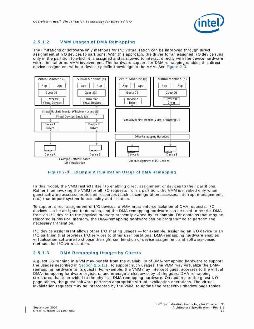
2.5.1.2 VMM Usages of DMA Remapping
The limitations of software-only methods for I/O virtualization can be improved through direct assignment of I/O devices to partitions. With this approach, the driver for an assigned I/O device runs only in the partition to which it is assigned and is allowed to interact directly with the device hardware with minimal or no VMM involvement. The hardware support for DMA remapping enables this direct device assignment without device-specific knowledge in the VMM. See Figure 2-3.
In this model, the VMM restricts itself to enabling direct assignment of devices to their partitions. Rather than invoking the VMM for all I/O requests from a partition, the VMM is invoked only when guest software accesses protected resources (such as configuration accesses, interrupt management, etc.) that impact system functionality and isolation.
To support direct assignment of I/O devices, a VMM must enforce isolation of DMA requests. I/O devices can be assigned to domains, and the DMA-remapping hardware can be used to restrict DMA from an I/O device to the physical memory presently owned by its domain. For domains that may be relocated in physical memory, the DMA-remapping hardware can be programmed to perform the necessary translation.
I/O device assignment allows other I/O sharing usages — for example, assigning an I/O device to an I/O partition that provides I/O services to other user partitions. DMA-remapping hardware enables virtualization software to choose the right combination of device assignment and software-based methods for I/O virtualization.
2.5.1.3 DMA Remapping Usages by Guests
A guest OS running in a VM may benefit from the availability of DMA-remapping hardware to support the usages described in Section 2.5.1.1. To support such usages, the VMM may virtualize the DMA-remapping hardware to its guests. For example, the VMM may intercept guest accesses to the virtual DMA-remapping hardware registers, and manage a shadow copy of the guest DMA-remapping structures that is provided to the physical DMA-remapping hardware. On updates to the guest I/O page tables, the guest software performs appropriate virtual invalidation operations. The virtual invalidation requests may be intercepted by the VMM, to update the respective shadow page tables
Figure 2-3. Example Virtualization Usage of DMA Remapping
VM
0
App App
Virtual Machine Monitor (VMM) or Hosting OS
Physical Host Hardware
Virtual Machine (0)
Guest OS
App App
Device A
Device A Driver
Device B Driver
Virtual Devices Emulation
Driver for Virtual Devices
Device B
VM
0
App App
Virtual Machine (n)
Guest OS
App App
Driver for Virtual Devices
VM
0
App App
Virtual Machine Monitor (VMM) or Hosting OS
Virtual Machine (0)
Guest OS
App App
Device A Device B
VM
0
App App
Virtual Machine (n)
Guest OS
App App
Device A Driver
Device B Driver
Example Software-based I/O Virtualization Direct Assignment of I/O Devices
DMA-Remapping Hardware
Intel® Virtualization Technology for Directed I/O—Overview
Intel® Virtualization Technology for Directed I/OArchitecture Specification - Rev 1.1 September 200716 Order Number: D51397-003
and perform invalidations of remapping hardware. Due to the non-restartability of faulting DMA transactions (unlike CPU memory management virtualization), a VMM cannot perform lazy updates to its shadow DMA-remapping structures. To keep the shadow structures consistent with the guest structures, the VMM may expose virtual remapping hardware with eager pre-fetching behavior (including caching of not-present entries) or use processor memory management mechanisms to write-protect the guest DMA-remapping structures.
2.5.1.4 Interaction with Processor Virtualization
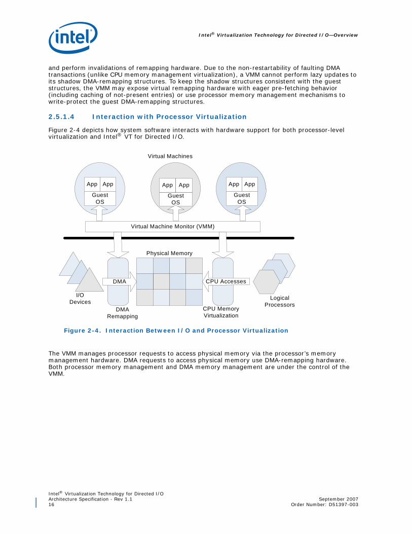
Figure 2-4 depicts how system software interacts with hardware support for both processor-level virtualization and Intel® VT for Directed I/O.
The VMM manages processor requests to access physical memory via the processor’s memory management hardware. DMA requests to access physical memory use DMA-remapping hardware. Both processor memory management and DMA memory management are under the control of the VMM.
Figure 2-4. Interaction Between I/O and Processor Virtualization
Virtual Machine Monitor (VMM)
GuestOS
App App
GuestOS
App App
GuestOS
App App
Physical Memory
CPU Accesses
Logical Processors
DMA
I/O Devices
Virtual Machines
DMA Remapping
CPU Memory Virtualization

Intel® Virtualization Technology for Directed I/OSeptember 2007 Architecture Specification - Rev 1.1Order Number: D51397-003 17
Overview—Intel® Virtualization Technology for Directed I/O
2.5.2 Hardware Support for Interrupt Remapping
Interrupt remapping provides hardware support for remapping and routing of interrupt requests from I/O devices (generated directly or through I/O interrupt controllers). The indirection achieved through remapping enables isolation of interrupts across partitions.
The following usages are envisioned for the interrupt-remapping hardware.
2.5.2.1 Interrupt Isolation
On Intel architecture platforms, interrupt requests are identified by the Root-Complex as write transactions targeting an architectural address range (0xFEEx_xxxxh). The interrupt requests are self-describing (i.e., attributes of the interrupt request are encoded in the request address and data), allowing any DMA initiator to generate interrupt messages with arbitrary attributes.
The interrupt-remapping hardware may be utilized by a Virtual Machine Monitor (VMM) to improve the isolation of external interrupt requests across domains. For example, the VMM may utilize the interrupt-remapping hardware to distinguish interrupt requests from specific devices and route them to the appropriate VMs to which the respective devices are assigned. The VMM may also utilize the interrupt-remapping hardware to control the attributes of these interrupt requests (such as destination CPU, interrupt vector, delivery mode etc.).
Another example usage is for the VMM to use the interrupt-remapping hardware to disambiguate external interrupts from the VMM owned inter-processor interrupts (IPIs). Software may enforce this by ensuring none of the remapped external interrupts have attributes (such as vector number) that matches the attributes of the VMM IPIs.
2.5.2.2 Interrupt Migration
The interrupt-remapping architecture may be used to support dynamic re-direction of interrupts when the target for an interrupt request is migrated from one logical processor to another logical processor. Without interrupt-remapping hardware support, re-balancing of interrupts require software to re-program the interrupt sources. However re-programming of these resources are non-atomic (requires multiple registers to be re-programmed), often complex (may require temporary masking of interrupt source), and dependent on interrupt source characteristics (e.g. no masking capability for some interrupt sources; edge interrupts may be lost when masked on some sources, etc.)
Interrupt-remapping enables software to efficiently re-direct interrupts without re-programming the interrupt configuration at the sources. Interrupt migration may be used by OS software for balancing load across processors (such as when running I/O intensive workloads), or by the VMM when it migrates virtual CPUs of a partition with assigned devices across physical processors to improve CPU utilization.
2.5.2.3 x2APIC Support
Intel®64 x2APIC architecture extends the APIC addressability to 32-bits (from 8-bits). Refer to Intel®64 x2APIC Architecture Specification for details.
Interrupt remapping enables x2APICs to support the expanded APIC addressability for external interrupts without requiring hardware changes to interrupt sources (such as I/OxAPICs and MSI/MSI-X devices).
Intel® Virtualization Technology for Directed I/O—DMA Remapping
Intel® Virtualization Technology for Directed I/OArchitecture Specification - Rev 1.1 September 200718 Order Number: D51397-003
3 DMA Remapping
This chapter describes the hardware architecture for DMA remapping. The architecture envisions DMA-remapping hardware to be implemented in Root-Complex components, such as the memory controller hub (MCH) or I/O hub (IOH).
3.1 Domains and Address Translation
A domain is abstractly defined as an isolated environment in the platform, to which a subset of the host physical memory is allocated. I/O devices that are allowed to access physical memory directly are allocated to a domain and are referred to as the domain’s assigned devices.
The isolation property of a domain is achieved by blocking access to its physical memory from resources not assigned to it. Multiple isolated domains are supported in a system by ensuring that all I/O devices are assigned to some domain (possibly a null domain), and that they can only access the physical resources allocated to their domain. The DMA remapping architecture facilitates flexible assignment of I/O devices to an arbitrary number of domains. Each domain has a view of physical address space that may be different than the host physical address space. DMA remapping treats the address specified in a DMA request as a DMA-Virtual Address (DVA). Depending on the software usage model, the DMA virtual address space may be the same as the Guest-Physical Address (GPA) space of the domain to which the I/O device is assigned, or a purely virtual address space defined by software. In either case, DMA remapping transforms the address in a DMA request issued by an I/O device to its corresponding Host-Physical Address (HPA).
For simplicity, this document refers to an address in a DMA request as a GPA and the translated address as an HPA.
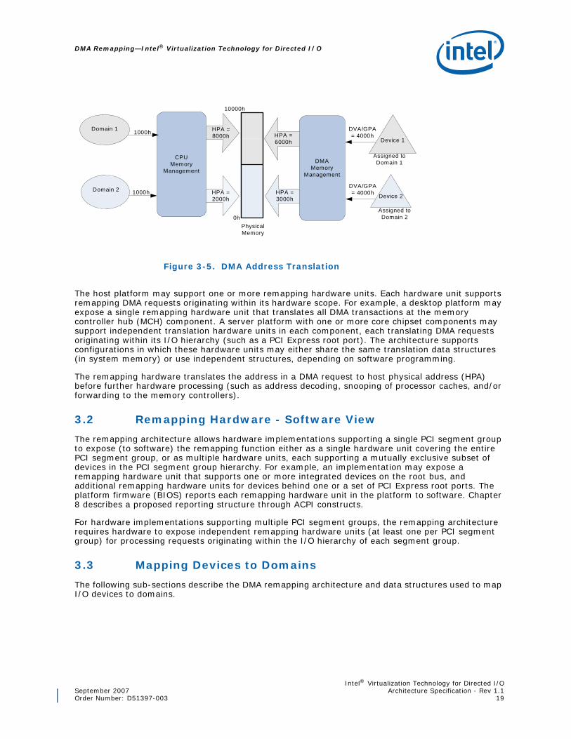
Figure 3-5 illustrates DMA address translation. I/O devices 1 and 2 are assigned to domains 1 and 2, respectively. The software responsible for creating and managing the domains allocates system physical memory for both domains and sets up the DMA address translation function. GPAs in DMA requests initiated by devices 1 & 2 are translated to appropriate HPAs by the DMA-remapping hardware.
Intel® Virtualization Technology for Directed I/OSeptember 2007 Architecture Specification - Rev 1.1Order Number: D51397-003 19
DMA Remapping—Intel® Virtualization Technology for Directed I/O
The host platform may support one or more remapping hardware units. Each hardware unit supports remapping DMA requests originating within its hardware scope. For example, a desktop platform may expose a single remapping hardware unit that translates all DMA transactions at the memory controller hub (MCH) component. A server platform with one or more core chipset components may support independent translation hardware units in each component, each translating DMA requests originating within its I/O hierarchy (such as a PCI Express root port). The architecture supports configurations in which these hardware units may either share the same translation data structures (in system memory) or use independent structures, depending on software programming.
The remapping hardware translates the address in a DMA request to host physical address (HPA) before further hardware processing (such as address decoding, snooping of processor caches, and/or forwarding to the memory controllers).
3.2 Remapping Hardware - Software View
The remapping architecture allows hardware implementations supporting a single PCI segment group to expose (to software) the remapping function either as a single hardware unit covering the entire PCI segment group, or as multiple hardware units, each supporting a mutually exclusive subset of devices in the PCI segment group hierarchy. For example, an implementation may expose a remapping hardware unit that supports one or more integrated devices on the root bus, and additional remapping hardware units for devices behind one or a set of PCI Express root ports. The platform firmware (BIOS) reports each remapping hardware unit in the platform to software. Chapter 8 describes a proposed reporting structure through ACPI constructs.
For hardware implementations supporting multiple PCI segment groups, the remapping architecture requires hardware to expose independent remapping hardware units (at least one per PCI segment group) for processing requests originating within the I/O hierarchy of each segment group.
3.3 Mapping Devices to Domains
The following sub-sections describe the DMA remapping architecture and data structures used to map I/O devices to domains.
Figure 3-5. DMA Address Translation
HPA = 8000h HPA =
6000h
Assigned to Domain 1
HPA = 2000h
Domain 2
Domain 1
0h
10000h
Assigned to Domain 2
DVA/GPA = 4000h
Physical Memory
HPA = 3000h
CPU Memory
Management
Device 2
Device 1
DMA Memory
Management
1000h
DVA/GPA = 4000h1000h

Intel® Virtualization Technology for Directed I/O—DMA Remapping
Intel® Virtualization Technology for Directed I/OArchitecture Specification - Rev 1.1 September 200720 Order Number: D51397-003
3.3.1 Source Identifier
DMA and interrupt requests appearing at the address-translation hardware is required to identify the device originating the request. The attribute identifying the originator of an I/O transaction is referred to as the “source-id” in this document. The remapping hardware may determine the source-id of a transaction in implementation-specific ways. For example, some I/O bus protocols may provide the originating device identity as part of each I/O transaction. In other cases (for Root-Complex integrated devices, for example), the source-id may be derived based on the Root-Complex internal implementation.
For PCI Express devices, the source-id is the requester identifier in the PCI Express transaction layer header. The requester identifier of a device, which is composed of its PCI Bus/Device/Function number, is assigned by configuration software and uniquely identifies the hardware function that initiated the request. Figure 3-6 illustrates the requester-id1 as defined by the PCI Express Specification.
The following sections describe the data structures for mapping I/O devices to domains.
3.3.2 Root-Entry
The root-entry functions as the top level structure to map devices on a specific PCI bus to their respective domains. Each root-entry structure contains the following fields:
• Present flag: The present field is used by software to indicate to hardware whether the root-entry is present and initialized. Software may Clear the present field for root entries corresponding to bus numbers that are either not present in the platform, or don’t have any downstream devices attached. If the present field of a root-entry used to process a DMA request is Clear, the DMA request is blocked, resulting in a translation fault.
• Context-entry table pointer: The context-entry table pointer references the context-entry table for devices on the bus identified by the root-entry. Section 3.3.3 describes context entries in further detail.
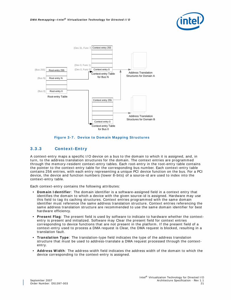
Section 9.1 illustrates the root-entry format. The root entries are programmed through the root-entry table. The location of the root-entry table in system memory is programmed through the Root-entry Table Address register. The root-entry table is 4KB in size and accommodates 256 root entries to cover the PCI bus number space (0-255). In the case of a PCI device, the bus number (upper 8-bits) encoded in a DMA transaction’s source-id field is used to index into the root-entry structure. Figure 3-7 illustrates how these tables are used to map devices to domains.
1. For PCI Express devices supporting Alternative Routing-ID Interpretation (ARI), bits traditionally used for the Device Number field in the Requester-id are used instead to expand the Function Number field.
Figure 3-6. Requester Identifier Format
0237815
Bus # Device # Function #
Intel® Virtualization Technology for Directed I/OSeptember 2007 Architecture Specification - Rev 1.1Order Number: D51397-003 21
DMA Remapping—Intel® Virtualization Technology for Directed I/O
3.3.3 Context-Entry
A context-entry maps a specific I/O device on a bus to the domain to which it is assigned, and, in turn, to the address translation structures for the domain. The context entries are programmed through the memory-resident context-entry tables. Each root-entry in the root-entry table contains the pointer to the context-entry table for the corresponding bus number. Each context-entry table contains 256 entries, with each entry representing a unique PCI device function on the bus. For a PCI device, the device and function numbers (lower 8-bits) of a source-id are used to index into the context-entry table.
Each context-entry contains the following attributes:
• Domain Identifier: The domain identifier is a software-assigned field in a context entry that identifies the domain to which a device with the given source-id is assigned. Hardware may use this field to tag its caching structures. Context entries programmed with the same domain identifier must reference the same address translation structure. Context entries referencing the same address translation structure are recommended to use the same domain identifier for best hardware efficiency.
• Present Flag: The present field is used by software to indicate to hardware whether the context-entry is present and initialized. Software may Clear the present field for context entries corresponding to device functions that are not present in the platform. If the present field of a context-entry used to process a DMA request is Clear, the DMA request is blocked, resulting in a translation fault.
• Translation Type: The translation-type field indicates the type of the address translation structure that must be used to address-translate a DMA request processed through the context-entry.
• Address Width: The address-width field indicates the address width of the domain to which the device corresponding to the context-entry is assigned.
Figure 3-7. Device to Domain Mapping Structures
Root-entry Table
Context-entry Tablefor Bus N
Context-entry Tablefor Bus 0
Root entry 0
Root entry N
Root entry 255Address Translation
Structures for Domain A
Address TranslationStructures for Domain B
Context entry 0
Context entry 255
(Dev 0, Func 0)
(Dev 31, Func 7)
(Dev 0, Func 1)
Context entry 255
Context entry 0
(Bus 0)
(Bus 255)
(Bus N)

Intel® Virtualization Technology for Directed I/O—DMA Remapping
Intel® Virtualization Technology for Directed I/OArchitecture Specification - Rev 1.1 September 200722 Order Number: D51397-003
• Address Space Root: The address-space-root field provides the host physical address of the address translation structure in memory to be used for address-translating DMA requests processed through the context-entry.
• Fault Processing Disable Flag: The fault-processing-disable field enables software to selectively disable recording and reporting of remapping faults detected for DMA requests processed through the context-entry.
Section 9.2 illustrates the exact context-entry format. Multiple devices may be assigned to the same domain by programming the context entries for the devices to reference the same translation structures, and programming them with the same domain identifier.
3.3.3.1 Context Caching
The DMA remapping architecture enables hardware to cache root-entries and context-entries in a context-cache to minimize the overhead incurred for fetching them from memory. Hardware manages the context-cache and supports context-cache invalidation requests by software.
When modifying device-to-domain mapping structures referenced by multiple remapping hardware units in a platform, software is responsible for explicitly invalidating the caches at each of the hardware units. Section 6.1.1 provides more details on the hardware caching behavior.
3.4 Address Translation
DMA remapping uses a multi-level, page-table-based address-translation structure.
3.4.1 Multi-Level Page Table
The multi-level page tables allow software to manage host physical memory at page (4KB) granularity and set up a hierarchical structure with page directories and page tables. Hardware implements the page-walk logic and traverses these structures using the address from the DMA request. The maximum number of page-table levels that need to be traversed is a function of the address width of the domain (specified in the corresponding context-entry).
The architecture defines the following features for the multi-level page table structure:
• Super Pages
— The super-page field in page-table entries enables larger page allocations. When a page-table entry with the super-page field set is encountered by hardware on a page-table walk, the translated address is formed immediately by combining the page base address in the page-table entry with the unused guest-physical address bits.
— The architecture defines super-pages of size 221, 230, 239 and 248. Implementations indicate support for specific super-page sizes through the Capability register. Hardware implementations may optionally support these super-page sizes.
• DMA Access Controls
— DMA access controls make it possible to control DMA accesses to specific regions within a domain’s address space. These controls are defined through the Read and Write permission fields.
— If hardware encounters a page-table entry with the Read field Clear as part of address-translating a DMA read request, the request is blocked1.
— If hardware encounters a page-table entry with the Write field Clear as part of address translating a DMA write request, the request is blocked.
1. Refer to Section 3.6.3 for handling Zero-Length DMA read requests to present pages without read-permissions.

Intel® Virtualization Technology for Directed I/OSeptember 2007 Architecture Specification - Rev 1.1Order Number: D51397-003 23
DMA Remapping—Intel® Virtualization Technology for Directed I/O
Figure 3-8 shows a multi-level (3-level) page-table structure with 4KB page mappings and 4KB page tables. Figure 3-9 shows a 2-level page-table structure with 2MB super pages.
Figure 3-8. Example Multi-level Page Table
Figure 3-9. Example Multi-level Page Table (with 2MB Super Pages)
DMA with address bits 63:39 validated to be 0s
38
12
11 0
SP =0
ContextEntry
ASR
30
,
+
<< 3 +
+
+
20
21
29
9-bi
ts
9-bi
ts
9-bi
ts
4KB page table ,4KB page table
4KB page table
4KB page
12-b
its127
12
63 0
<< 3
<< 3
0s
63
39
SP = 0
SP = 0
38
12
11 0
ContextEntry
ASR
30
,
+
<< 3
<< 3
+
+
20
21
29
9-bi
ts
9-bi
ts
4KB page table,4KB page table
2MB page
21-b
its
127
12
63 0
0s
63
39 DMA with address bits
63:39 validated to be 0s
SP = 0
SP = 1

Intel® Virtualization Technology for Directed I/O—DMA Remapping
Intel® Virtualization Technology for Directed I/OArchitecture Specification - Rev 1.1 September 200724 Order Number: D51397-003
3.4.2 Adjusted Guest Address Width (AGAW)
To allow page-table walks with 9-bit stride, the Adjusted Guest Address Width (AGAW) value for a domain is defined as its Guest Address Width (GAW) value adjusted, such that (AGAW-12) is a multiple of 9. For example, a domain to which 2GB of memory is allocated has a GAW of 31, and an AGAW of 39. AGAW is calculated as follows:
R = (GAW - 12) MOD 9;if (R == 0) {
AGAW = GAW;} else {
AGAW = GAW + 9 - R;}if (AGAW > 64)
AGAW = 64;
The AGAW indicates the number of levels of page-walk. Hardware implementations report the supported AGAWs through the Capability register. Software must ensure that it uses an AGAW supported by the underlying hardware implementation when setting up page tables for a domain.
3.4.3 Multi-level Page Table Translation
Address translation of DMA requests processed through a context-entry specifying use of multi-level page tables is handled by remapping hardware as follows:
1. If the GPA in the DMA request is to an address above the maximum guest address width supported by the remapping hardware (as reported through the MGAW field in the Capability register), the DMA request is blocked.
2. If the address-width (AW) field programmed in the context-entry is not one of the AGAWs supported by hardware (as reported through the SGAW field in the Capability register), the DMA request is blocked.
3. The address of the DMA request is validated to be within the adjusted address width of the domain to which the device is assigned. DMA requests attempting to access memory locations above address (2X - 1) are blocked, where X is the AGAW corresponding to the address-width programmed in the context-entry used to process this DMA request.
4. The adjusted address of the DMA request is translated through the multi-level page table referenced by the context-entry. Based on the programming of the page-table entries1 (Super-page, Read, Write attributes), either the adjusted address is successfully translated to a Host Physical Address (HPA), or the DMA request is blocked.
5. For successful address translations, hardware performs the normal processing (address decoding, etc.) of the DMA request as if it was targeting the translated HPA.
1. Software must ensure the DMA-remapping page tables are programmed not to remap regular DMA requests to the interrupt address range (0xFEEx_xxxx). Hardware behavior is undefined for DMA requests remapped to the interrupt address range.

Intel® Virtualization Technology for Directed I/OSeptember 2007 Architecture Specification - Rev 1.1Order Number: D51397-003 25
DMA Remapping—Intel® Virtualization Technology for Directed I/O
3.4.4 I/O Translation Lookaside Buffer (IOTLB)
The DMA remapping architecture defines support for caching effective translations1 for improved address translation performance. The cache of effective translations is referred to as the I/O translation look-aside buffer (IOTLB). Similar to the context-cache, hardware manages the IOTLB, and supports IOTLB invalidation requests by software. Details of the hardware caching and invalidation behavior are described in Section 6.1.2.
3.5 DMA Remapping Fault Conditions
Table 3 enumerates the various conditions resulting in faults when processing DMA requests with untranslated2 address. A fault condition is considered ‘qualified’ if its reported to software only when the Fault Processing Disable (FPD) field in the context-entry used to process the faulting request is Clear.
3.5.1 Hardware Handling of Faulting DMA Requests
DMA requests that result in remapping faults must be blocked by hardware. The exact method of DMA blocking is implementation-specific. For example:
• Faulting DMA write requests may be handled in much the same way as hardware handles write requests to non-existent memory. For example, the DMA request is discarded in a manner convenient for implementations (such as by dropping the cycle, completing the write request to memory with all byte enables masked off, re-directed to a dummy memory location, etc.).
• Faulting DMA read requests may be handled in much the same way as hardware handles read requests to non-existent memory. For example, the request may be redirected to a dummy memory location, returned as all 0’s or 1’s in a manner convenient to the implementation, or the request may be completed with an explicit error indication (preferred). For faulting DMA read requests from PCI Express devices, hardware must indicate “Unsupported Request” (UR) in the completion status field of the PCI Express read completion.3
1. When inserting a leaf page-table entry into the IOTLB, hardware caches the Read (R) and Write (W) attributes as the logical AND of all the respective R and W fields encountered in the page walk reaching up to this leaf entry.
2. For PCI Express, DMA requests with untranslated (default) address are identified by the Address Type (AT) field value of 00b in the Transaction Layer Packet (TLP) header.
3. For PCI Express, a DMA read completion with an error status may cause hardware to generate a PCI Express un-correctable, non-fatal (ERR_NONFATAL) error message.

Intel® Virtualization Technology for Directed I/O—DMA Remapping
Intel® Virtualization Technology for Directed I/OArchitecture Specification - Rev 1.1 September 200726 Order Number: D51397-003
Table 3. Unsuccessful DMA requests
Fault Conditions1 Fault Reason Qualified Behavior
The Present (P) field in the root-entry used to process the DMA request is Clear. 1h No
Unsupported Request
The Present (P) field in the context-entry used to process the DMA request is Clear. 2h
Yes
Hardware detected invalid programming of a context-entry. For example:• The Address-Width (AW) field was programmed with an value
not supported by the hardware implementation.• The Translation-Type (T) field was programmed to indicate a
translation type not supported by the hardware implementation.• Hardware attempt to access the page-table base through the
Address Space Root (ASR) field of the context-entry resulted in error.
3h
The DMA request attempted to access an address2 beyond (2X - 1), where X is the minimum of the MGAW reported in the Capability register and the value in the address-width (AW) field of the context-entry used to process the request.
4h
The Write (W) field in a page-table entry used to remap the DMA write request is Clear. 5h
The Read (R) field in a page-table entry used to remap the DMA read request is Clear. For implementations reporting ZLR field as set in the Capability register, this fault condition is not applicable for zero-length DMA read requests to write-only pages.
6h
Hardware attempt to access the next level page table through the Address (ADDR) field of the page-table entry resulted in error. 7h
Hardware attempt to access the root-entry table through the root-table address (RTA) field in the Root-entry Table Address register resulted in error.
8h
NoHardware attempt to access context-table through context-entry table pointer (CTP) field resulted in error. 9h
Hardware detected non-zero reserved fields in a root-entry with Present (P) field Set. Ah
Hardware detected non-zero reserved fields in a context-entry with Present (P) field Set. Bh
YesHardware detected non-zero reserved fields in a page-table entry with at least one of the Read (R) and Write (W) fields Set. Ch
1. Non-recoverable error conditions encountered by the remapping hardware are not treated as DMA-remappingfault conditions. These are treated as platform hardware errors and reported through existing error reportingmethods such as NMI, MCA etc.
2. DMA requests to addresses beyond the maximum guest address width (MGAW) supported by hardware may bereported through other means such as through PCI Express Advanced Error Reporting (AER) at a PCI Expressroot port.

Intel® Virtualization Technology for Directed I/OSeptember 2007 Architecture Specification - Rev 1.1Order Number: D51397-003 27
DMA Remapping—Intel® Virtualization Technology for Directed I/O
3.6 DMA Remapping - Usage Considerations
This section describes the various DMA-remapping hardware usage considerations.
3.6.1 Identifying Origination of DMA Requests
In order to support isolation usages, the platform must be capable of uniquely identifying the requestor (Source-Id) for each DMA request. The DMA sources in a platform and use of source-id in these requests may be categorized as below.
3.6.1.1 Devices Behind PCI Express to PCI/PCI-X Bridges
The PCI Express-to-PCI/PCI-X bridges may generate a different requester-id and tag combination in some instances for transactions forwarded to the bridge’s PCI Express interface. The action of replacing the original transaction’s requester-id with one assigned by the bridge is generally referred to as taking ‘ownership’ of the transaction. If the bridge generates a new requester-id for a transaction forwarded from the secondary interface to the primary interface, the bridge assigns the PCI Express requester-id using the secondary interface’s bus number, and sets both the device number and function number fields to zero. Refer to the PCI Express-to-PCI/PCI-X bridge specifications for more details.
For remapping requests from devices behind PCI Express-to-PCI/PCI-X bridges, software must consider the possibility of requests arriving with the source-id in the original PCI-X transaction or the source-id provided by the bridge. Devices behind these bridges can only be collectively assigned to a single domain. When setting up DMA-remapping structures for these devices, software must program multiple context entries, each corresponding to the possible set of source-ids. Each of these context-entries must be programmed identically to ensure the DMA requests with any of these source-ids are processed identically.
3.6.1.2 Devices Behind Conventional PCI Bridges
For devices behind conventional PCI bridges, the source-id in the DMA requests is the requester-id of the bridge device. For remapping requests from devices behind conventional PCI bridges, software must program the context-entry corresponding to the bridge device. Devices behind these bridges can only be collectively assigned to a single domain.
3.6.1.3 Root-Complex Integrated Devices
Transactions generated by all root-complex integrated devices must be uniquely identifiable through its source-id (PCI requester-id). This enables any root-complex integrated endpoint device (PCI or PCI-Express) to be independently assigned to a domain.
3.6.1.4 PCI Express Devices Using Phantom Functions
To increase the maximum possible number of outstanding requests requiring completion, PCI Express allows a device to use function numbers not assigned to implemented functions to logically extend the Tag identifier. Unclaimed function numbers are referred to as Phantom Function Numbers (PhFN). A device reports its support for phantom functions through the Device Capability configuration register, and requires software to explicitly enable use of phantom functions through the Device Control configuration register.
Since the function number is part of the requester-id used to locate the context-entry for processing a DMA request, when assigning PCI Express devices with phantom functions enabled, software must program multiple context entries, each corresponding to the PhFN enabled for use by the device function. Each of these context-entries must be programmed identically to ensure the DMA requests with any of these requester-ids are processed identically.

Intel® Virtualization Technology for Directed I/O—DMA Remapping
Intel® Virtualization Technology for Directed I/OArchitecture Specification - Rev 1.1 September 200728 Order Number: D51397-003
3.6.2 Handling DMA Requests Crossing Page Boundaries
PCI Express memory requests are specified to disallow address/length combinations which cause a memory space access to cross a page (4KB) boundary. However, the PCI Express Specification defines checking for violations of this rule at the receivers as optional. If checked, violations are treated as malformed transaction layer packets and reported as PCI Express errors. Checking for violations from Root-Complex integrated devices is typically platform-dependent.
Platforms supporting DMA remapping are expected to check for violations of the rule in one of the following ways:
• The platform hardware checks for violations and explicitly blocks them. For PCI Express memory requests, this may be implemented by hardware that checks for the condition at the PCI Express receivers and handles violations as PCI Express errors. DMA requests from other devices (such as Root-Complex integrated devices) that violate the rule (and hence are blocked by hardware) may be handled in platform-specific ways. In this model, the remapping hardware units never receive DMA requests that cross page boundaries.
• If the platform hardware cannot check for violations, the remapping hardware units must perform these checks and re-map the requests as if they were multiple independent DMA requests.
3.6.3 Handling of Zero-Length Reads
A memory read request of one double-word with no bytes enabled (“zero-length read”) is typically used by devices as a type of flush request. For a requester, the semantics of the flush request allow a device to ensure that previously issued posted writes in the same traffic class have been completed at its destination.
Zero-length read requests are handled as follows by remapping hardware:
• Implementations reporting ZLR field as Clear in the Capability register process zero-length read requests like any other read requests. Specifically, zero-length read requests are address-translated based on the programming of the DMA-remapping structures. Zero-length reads translated to memory are completed in the coherency domain with all byte enables off. Unsuccessful translations result in DMA-remapping faults. For example, zero-length read requests to write-only pages are blocked due to read permission violation.
• Implementations reporting ZLR field as Set in the Capability register handles zero-length read requests same as above, except if it is to a write-only page. Zero-length read requests to write-only pages that do not encounter any faulting conditions other than read permission violation are successfully remapped and completed. Zero-length reads translated to memory complete in the coherency domain with all byte enables off. Data returned in the read completion is obfuscated.
DMA remapping hardware implementations are recommended to report ZLR field as Set and support the associated hardware behavior.
3.6.4 Handling DMA to Reserved System Memory
Reserved system memory regions are typically allocated by BIOS at boot time and reported to OS as reserved address ranges in the system memory map. DMA to these reserved regions may either occur as a result of operations performed by the system software driver (for example in the case of DMA from UMA graphics controllers to graphics reserved memory), or may be initiated by non system software (for example in case of DMA performed by a USB controller under BIOS SMM control for legacy keyboard emulation). For proper functioning of these legacy reserved memory usages, when system software enables DMA remapping, the DMA-remapping page tables for the respective devices are expected to be setup to provide identity mapping for the specified reserved memory regions with DMA read and write permissions.

Intel® Virtualization Technology for Directed I/OSeptember 2007 Architecture Specification - Rev 1.1Order Number: D51397-003 29
DMA Remapping—Intel® Virtualization Technology for Directed I/O
Platform implementations supporting reserved memory must carefully consider the system software and security implications of its usages. These usages are beyond the scope of this specification. Platform hardware may use implementation-specific methods to distinguish accesses to system reserved memory. These methods must not depend on simple address-based decoding since DMA virtual addresses can indeed overlap with the host physical addresses of reserved system memory.
For platforms that cannot distinguish between DMA to OS-visible system memory and DMA to reserved system memory, the architecture defines a standard reporting method to inform system software about the reserved system memory address ranges and the specific devices that require DMA access to these ranges for proper operation. Refer to Section 8.4 for details on the reporting of reserved memory regions.
For legacy compatibility, system software is expected to setup identity mapping (with read and write privileges) for these reserved address ranges, for the specified devices1. For these devices, the system software is also responsible for ensuring that the DMA virtual addresses generated by the system software do not overlap with the reserved system memory address ranges.
3.6.5 Root-Complex Peer to Peer Considerations
When DMA remapping is enabled, peer-to-peer requests through the Root-Complex must be handled as follows:
• The address in the DMA request must be treated as a DMA virtual address and address-translated to an HPA. The address decoding for peer addresses must be done only on the translated HPA. Hardware implementations are free to further limit peer-to-peer accesses to specific host physical address regions (or to completely disallow peer-forwarding of translated requests).
• Since address translation changes the contents (address field) of the PCI Express Transaction Layer Packet (TLP), for PCI Express peer-to-peer requests with ECRC, the Root-Complex hardware must use the new ECRC (re-computed with the translated address) if it decides to forward the TLP as a peer request.
• Root-ports may support additional peer-to-peer control features by supporting PCI Express Access Control Services (ACS) capability. Refer to ACS ECR from PCI-SIG for additional details.
3.6.6 Handling of Isochronous DMA
PC platforms support varying classes of isochronous DMA traffic to support different real-time usages and devices. Examples of isochronous traffic supported by current PC platforms include:
• Legacy Isochrony: Legacy isochronous traffic refers to the support typically provided to applications that use legacy audio and USB controllers.
• PCI Express Isochrony: The PCI Express specification defines support for isochronous traffic to support real-time and Quality of Service (QoS) usages. An example of this class of isochrony is applications that use high-definition audio controllers.
• Integrated Graphics Isochrony: This applies to traffic generated by integrated graphics subsystems which typically have multiple real-time DMA streams for display, overlay, cursor, and legacy VGA usages.
There may be other classes of differentiated DMA streams in the platform to support future usages. Different classes of isochrony are typically implemented through traffic classification, Virtual Channels (VC), and priority mechanisms. DMA remapping of critical isochronous traffic may require special handling since the remapping process potentially adds additional latency to the isochronous paths.
Hardware recommendations and software requirements for efficient remapping of isochronous traffic are described below. The classes of isochrony that need to be subject to these requirements are platform-specific.
1. USB controllers and UMA integrated graphics devices are the only legacy device usages identified that depend on DMA to reserved system memory.

Intel® Virtualization Technology for Directed I/O—DMA Remapping
Intel® Virtualization Technology for Directed I/OArchitecture Specification - Rev 1.1 September 200730 Order Number: D51397-003
• Root-Complex hardware may utilize dedicated resources to support remapping of DMA accesses from isochronous devices. This may occur through dedicated remapping hardware units for isochronous devices, or through reservation of hardware resources (such as entries in various remapping caching structures) for remapping isochronous DMA.
• DMA-remapping units supporting isochronous traffic may pre-fetch and cache valid address translations. Under normal operation, to maintain isochronous guarantees, software should avoid invalidating mappings that are in-use by isochronous DMA requests active at the time of invalidation. The Capability register of each DMA-remapping unit indicates to software if the remapping unit manages critical isochronous DMA.

Intel® Virtualization Technology for Directed I/OSeptember 2007 Architecture Specification - Rev 1.1Order Number: D51397-003 31
Support For Device-IOTLBs—Intel® Virtualization Technology for Directed I/O
4 Support For Device-IOTLBs
The DMA remapping architecture described in previous chapter supports address translation of DMA requests received by the Root-Complex. Section 3.4.4 described the use of IOTLBs in these core logic components to cache frequently used I/O page-table entries to improve the DMA address translation performance. IOTLBs improve DMA remapping performance by avoiding the multiple memory accesses required to access the I/O page-tables for DMA address translation. However, the efficiency of IOTLBs in the core logic may depend on the address locality in DMA streams and the number of simultaneously active DMA streams in the platform.
One approach to scaling IOTLBs is to enable I/O devices to participate in the DMA remapping with IOTLBs implemented at the devices. The Device-IOTLBs alleviate pressure for IOTLB resources in the core logic, and provide opportunities for devices to improve performance by pre-fetching address translations before issuing DMA requests. This may be useful for devices with strict DMA latency requirements (such as isochronous devices), and for devices that have large DMA working set or multiple active DMA streams. Additionally, Device-IOTLBs may be utilized by devices to support device-specific I/O page faults.
Device-IOTLB support requires standardized mechanisms for:
• I/O devices to request and receive translations from the Root-Complex
• I/O devices to indicate if a DMA request has translated or un-translated addresses
• Translations cached at Device-IOTLBs to be invalidated
Refer to the Address Translation Services (ATS) specification from the PCI-SIG for extensions to PCI Express to support Device-IOTLBs. DMA-remapping implementations report Device-IOTLB support through the Extended Capability register.
4.1 Hardware Handling of ATS
ATS specification defines an ‘Address Type’ (AT) field in the PCI Express transaction layer header for memory requests. The AT field indicates if the transaction is a ‘Translation Request’, memory request with ‘Translated’ address, or memory request with ‘Untranslated’ address. ATS also defines new messages for Device-IOTLB ‘Invalidation Requests’ and ‘Invalidation Completion’.
4.1.1 Handling of ATS Protocol Errors
The following upstream transactions are always handled as malformed packets:
• Memory read or write request with an AT field value of ‘Reserved’.
• Memory write request with an AT field value of ‘Translation Request’.
• Memory read request with AT field value of ‘Translation Request’ with any of the following:
— Length field specifying odd number of DWORDs (i.e. least significant bit of length field is non-zero)
— Length field greater than N/4 DWORDs where N is the Read Completion Boundary (RCB) value (in bytes) supported by the Root-Complex.
— First and last DWORD byte enable (BE) fields not equal to 1111b.
• ATS ‘Invalidation Request’ message.

Intel® Virtualization Technology for Directed I/O—Support For Device-IOTLBs
Intel® Virtualization Technology for Directed I/OArchitecture Specification - Rev 1.1 September 200732 Order Number: D51397-003
4.1.2 Root Port Handling of ATS
Root ports supporting Access Control Services (ACS) capability may support ‘Translation Blocking’ ability to block upstream memory requests with non-zero value in AT field. When enabled, such requests are reported as ACS violation associated with the receiving port. Refer to the ACS ECR from PCI-SIG for more details. Upstream requests that cause ACS violations are blocked at the root port and not presented to remapping hardware.
4.1.3 Handling of ATS When Remapping Hardware Disabled
When DMA-remapping hardware is not enabled (TES field Clear in Global Status register), following upstream transactions are treated as Unsupported Request (UR).
• Memory requests with non-zero AT field (i.e. AT field not ‘Untranslated’).
• ATS ‘Invalidation Completion’ messages.
4.1.4 Handling of Translation Requests
This section describes the handling of translation requests when remapping hardware is enabled.
• Table 4 illustrates the hardware handling of various error conditions leading to an unsuccessful translation request. These errors are treated as remapping faults. A fault condition is considered ‘qualified’ if its reported to software only when the Fault Processing Disable (FPD) field in the context-entry used to process the faulting request is Clear.
• When none of the error conditions in Table 4 is detected, hardware handles the successful translation requests as illustrated in Table 4-2.

Intel® Virtualization Technology for Directed I/OSeptember 2007 Architecture Specification - Rev 1.1Order Number: D51397-003 33
Support For Device-IOTLBs—Intel® Virtualization Technology for Directed I/O
Table 4. Unsuccessful Translation Requests
Unsuccessful Translation Request Conditions Fault Reason Qualified
Translation Completion
Status
Conditions that explicitly block the translation request:
• Present (P) field in the root-entry used to process the translation request is Clear. 1h No
Unsupported Request
• Present (P) field in the context-entry used to the process translation request is Clear. 2h
Yes• Present context-entry used to process translation request
specifies blocking of Translation Requests (Translation Type (T) field value not equal to 01b).
Dh
Erroneous conditions detected by hardware:
• Hardware detected invalid programming of a context-entry. For example:
• The address width (AW) field programmed with a value not supported by the hardware implementation.
• The translation-type (T) field programmed to indicate a translation type not supported by the hardware imple-mentation.
• Hardware attempt to access the page table base through the Address Space Root (ASR) field of the context-entry resulted in error.
3h
Yes
Completer Abort1
1. ATS specification requires Completer Abort (CA) to be returned for unsuccessful translation requests dueto remapping hardware error. Errors due to improper programming of remapping structures are treatedsimilarly and return CA.
• Hardware attempt to access the next level page-table through the Address (ADDR) field of the page-table entry resulted in error.
7h
• Hardware attempt to access the root-entry table through the Root Table Address (RTA) field in the Root-entry Table Address register resulted in error.
8h
No• Hardware attempt to access context-entry table through Context Table Pointer (CTP) field resulted in error. 9h
• Hardware detected reserved field(s) not initialized to zero in root-entry with Present (P) field Set. Ah
• Hardware detected reserved field(s) not initialized to zero in context-entry with Present (P) field Set. Bh
Yes• Hardware detected reserved field(s) not initialized to zero in a page-table entry with at least one of Read (R) and Write (W) field Set.
Ch

Intel® Virtualization Technology for Directed I/O—Support For Device-IOTLBs
Intel® Virtualization Technology for Directed I/OArchitecture Specification - Rev 1.1 September 200734 Order Number: D51397-003
4.1.4.1 Translation Requests for Multiple Translations
Translation Requests for multiple mappings indicate a length field greater than 2 DWORDs. Hardware implementations may handle these requests in any one of the following ways:
• Always return single translation
— Hardware fetches translation only for the starting address specified in the translation request, and a translation completion is returned depending on the result of this processing. In this case the translation completion has a Length of 2 DWORDs, Byte Count of 8, and the Lower Address indicates a value of RCB minus 8.
• Return multiple translations
— Hardware fetches translations starting with the address specified in the translation request, until a CA or UR condition is detected, or until a translation with different page-size than the previous translation in this request is detected. Hardware is also allowed to limit fetching of translations to those that are resident within a cacheline. When returning multiple translations (which may be less than the number of translation requested), hardware must ensure that successive translations must apply to the untranslated address range that abuts the previous translation in the same completion. Refer to the ATS specification for requirements for translation completions returning multiple mappings in one or two packets.
4.1.5 Handling of Translated Requests
This section describes the handling of Translated requests when remapping hardware is enabled.
Table 5. Successful Translation Requests
Successful Translation Request Conditions Translation Completion
Hardware detected address in the translation request is to the interrupt address range (0xFEEx_xxxx). The special handling to interrupt address range is to comprehend potential endpoint device ATS behavior of issuing translation requests to all of its memory transactions including its message signalled interrupt (MSI) posted writes.
Success (R=0,W=1,U=1,
S=0 in translation
completion data entry)
Conditions where hardware could not find a translation for address specified in translation request, or the requested translation lacked both read and write permissions. • The translation request had an address beyond (2X - 1), where X is the
minimum of the maximum guest address width (MGAW) reported through the Capability register and the value in the address-width (AW) field of the context-entry used to process the DMA request.
• Hardware found a not-present (R=W=0b) page-directory (non-leaf) entry along the page-walk for the address specified in the translation request, and hence could not complete page-walk.
• Hardware found the cumulative R and cumulative W bits to be both Clear along the page-walk on behalf of the translation request.
Success (R=W=U=S=0,in translation
completion data entry)
Hardware successfully fetched the effective translations requested and it has at least one of Read and Write permissions. • The R and W bits in the translation completion data entry are the effective
(cumulative) permissions for this translation. • The N and U bits are derived from the SNP and TM bits from the leaf page-table
entry for the translation.• Translations corresponding to 4KB pages indicate S bit in the translation
completion data entry as 0. Translations corresponding to super-pages indicate S bit as Set with low-order bits of the translated address field encoded to indicate the appropriate super-page size. See ATS specification for details on encoding.
• If U field is Clear, the address in the translation completion data entry is the translated address. If the U field is Set, the address in the translation completion data entry is not specified. The R and W fields returned in the translation completion data entry are not affected by the value of U field.
Success (with translation completion data entries per ATS specification)

Intel® Virtualization Technology for Directed I/OSeptember 2007 Architecture Specification - Rev 1.1Order Number: D51397-003 35
Support For Device-IOTLBs—Intel® Virtualization Technology for Directed I/O
• Translated writes to the interrupt address range (0xFEEx_xxxx) are treated as UR. Translated (and untranslated) reads to the interrupt address range always return UR.
• Table 6 illustrates the hardware handling of various error conditions leading to a failed Translated request. In these cases the request is blocked (handled as UR) and treated as remapping fault. A fault condition is considered ‘qualified’ if its reported to software only when the Fault Processing Disable (FPD) field in the context-entry used to process the faulting request is Clear.
• When none of the error conditions in Table 6 is detected, the Translated request is processed as pass-through (i.e. bypasses address translation).
4.2 Handling of Device-IOTLB Invalidations
The Address Translation Services (ATS) extensions to PCI Express defines the needed wire protocol for the Root-Complex to issue a Device-IOTLB invalidation request to an endpoint and to receive the Device-IOTLB invalidation completion responses from the endpoint.
For DMA-remapping implementations supporting Device-IOTLBs, software submits the Device-IOTLB invalidation requests through the invalidation queue interface of the remapping hardware. Section 6.2.2 describes the queued invalidation interface details.
Hardware processes a Device-IOTLB invalidation request as follows:
• Hardware allocates a free invalidation tag (ITag). ITags are used to uniquely identify an invalidation request issued to an endpoint. If there are no free ITags in hardware, the Device-IOTLB invalidation request is deferred until a free ITag is available. For each allocated ITag, hardware stores a counter (InvCmpCnt) to track the number of invalidation completions received with this ITag.
Table 6. Unsuccessful Translated Requests
Unsuccessful Translated Request Conditions Fault Reason Qualified Behavior
Present (P) field in the root-entry used to process the translation request is Clear. 1h No
Unsupported Request
Present (P) field in the context-entry used to the process translation request is Clear. 2h
Yes
Hardware detected invalid programming of a context-entry. For example:• The address width (AW) field programmed with a value not
supported by the hardware implementation.• The translation-type (T) field programmed to indicate a
translation type not supported by the hardware implementation.
3h
Hardware attempt to access the root-entry table through the Root Table Address (RTA) field in the Root-entry Table Address register resulted in error.
8h
NoHardware attempt to access context-entry table through Context Table Pointer (CTP) field resulted in error. 9h
Hardware detected reserved field(s) not initialized to zero in root-entry with Present (P) field Set. Ah
Hardware detected reserved field(s) not initialized to zero in context-entry with Present (P) field Set. Bh
YesPresent context-entry used to process translation request specifies blocking of Translation Requests (Translation Type (T) field value not equal to 01b).
Dh

Intel® Virtualization Technology for Directed I/O—Support For Device-IOTLBs
Intel® Virtualization Technology for Directed I/OArchitecture Specification - Rev 1.1 September 200736 Order Number: D51397-003
• Hardware starts an invalidation completion timer for this ITag, and issues the invalidation request message to the specified endpoint. The invalidation completion time-out value is recommended to be sufficiently larger than the PCI Express read completion time-outs.
Hardware processes a Device-IOTLB invalidation response received as follows:
• ITag-vector in the invalidation completion response indicates the ITags corresponding to completed Device-IOTLB invalidation requests. The completion count in the invalidation response indicates the number of invalidation completion messages expected with the same ITag-vector and completion count.
• For each ITag Set in the ITag-vector, hardware checks if it is a valid (currently allocated) ITag for the source-id in the invalidation completion response. If hardware detects an invalid ITag, the invalidation completion message is dropped by hardware. The error condition is reported by setting the Invalidation Completion Error (ICE) field in the Fault Status register, and depending on the programming of the Fault Control register a fault event may be generated.
• If above checks are completed successfully, for each ITag in the ITag-vector, the corresponding InvCmpCnt counter is incremented and compared with the ‘completion count’ value in the invalidation response (‘completion count’ value of 0 indicates 8 invalidation completions). If the comparison matches, the Device-IOTLB invalidation request corresponding to the ITag is considered completed, and the ITag is freed.
• If the invalidation completion time-out expires for an ITag before the invalidation response is received, hardware frees the ITag and reports it through the ITE field in the Fault Status register. Depending on the programming of the Fault Control register a fault event may be generated. Section 6.2.2.7 describes hardware behavior on invalidation completion time-outs.

Intel® Virtualization Technology for Directed I/OSeptember 2007 Architecture Specification - Rev 1.1Order Number: D51397-003 37
Interrupt Remapping—Intel® Virtualization Technology for Directed I/O
5 Interrupt Remapping
This chapter discuss architecture and hardware details for interrupt remapping. The interrupt-remapping architecture defined in this chapter is common for both Intel®64 and ItaniumTM architectures.
5.1 Overview
The interrupt-remapping architecture enables system software to control and censor external interrupt requests generated by all sources including those from interrupt controllers (I/OxAPICs), MSI/MSI-X capable devices including endpoints, root-ports and Root-Complex integrated end-points.
Interrupts generated by the remapping hardware itself (Fault Event and Invalidation Completion Events) are not subject to interrupt remapping.
Interrupt requests appear to the Root-Complex as upstream memory write requests to the interrupt-address-range 0xFEEX_XXXXh. Since interrupt requests arrive at the Root-Complex as write requests, interrupt-remapping is co-located with the DMA-remapping hardware units. The interrupt-remapping capability is reported through the Extended Capability register.
5.2 Identifying Origination of Interrupt Requests
To support domain-isolation usages, the platform hardware must be capable of uniquely identifying the requestor (Source-Id) for each interrupt message. The interrupt sources in a platform and use of source-id in these requests may be categorized as follows:
• Message Signaled Interrupts from PCI Express Devices
— For message-signaled interrupt requests from PCI Express devices, the source-id is the requester identifier in the PCI Express transaction header. The requester-id of a device is composed of its PCI Bus/Device/Function number assigned by configuration software and uniquely identifies the hardware function that initiated the I/O request. Section 3.3.1 illustrates the requester-id as defined by the PCI Express specification. Section 3.6.1.4 describes use of source-id field by PCI Express devices using phantom functions.
• Message Signaled Interrupts from Root Complex Integrated Devices
— For message-signaled interrupt requests from root-complex integrated PCI or PCI Express devices, the source-id is its PCI requester-id.
• Message Signaled Interrupts from Devices behind PCI Express to PCI/PCI-X Bridges
— For message-signaled interrupt requests from devices behind PCI Express-to-PCI/PCI-X bridges, the requester identifier in those interrupt requests may be that of the interrupting device or the requester-id with the bus number field equal to the bridge’s secondary interface’s bus number and device and function number fields value of zero. Section 3.6.1.1 describes legacy behavior of these bridges. Due to this aliasing, interrupt-remapping hardware does not isolate interrupts from individual devices behind such bridges.
• Message Signaled Interrupts from Devices behind Conventional PCI bridges
— For message-signaled interrupt requests from devices behind conventional PCI bridges, the source-id in those interrupt requests is the requestor-id of the legacy bridge device. Section 3.6.1.2 describes legacy behavior of these bridges. Due to this, interrupt-remapping
Intel® Virtualization Technology for Directed I/O—Interrupt Remapping
Intel® Virtualization Technology for Directed I/OArchitecture Specification - Rev 1.1 September 200738 Order Number: D51397-003
hardware does not isolate message-signaled interrupt requests from individual devices behind such bridges.
• Legacy pin interrupts
— For devices that use legacy methods for interrupt routing (such as either through direct wiring to the I/OxAPIC input pins, or through INTx messages), the I/OxAPIC hardware generates the interrupt-request transaction. To identify the source of interrupt requests generated by I/OxAPICs, the interrupt-remapping hardware requires each I/OxAPIC in the platform (enumerated through the ACPI Multiple APIC Descriptor Tables (MADT)) to include a unique 16-bit source-id in its requests. BIOS reports the source-id for these I/OxAPICs via ACPI structures to system software. Refer to Section 8.3.1.1 for more details on I/OxAPIC identity reporting.
• Other Message Signaled Interrupts
— For any other platform devices that are not PCI discoverable and yet capable of generating message-signaled interrupt requests (such as the integrated High Precision Event Timer - HPET devices), the platform must assign unique source-ids that do not conflict with any other source-ids on the platform. BIOS must report the 16-bit source-id for these via ACPI structures described in Section 8.3.1.2.

Intel® Virtualization Technology for Directed I/OSeptember 2007 Architecture Specification - Rev 1.1Order Number: D51397-003 39
Interrupt Remapping—Intel® Virtualization Technology for Directed I/O
5.3 Interrupt Processing On Intel®64 Platforms
Interrupt-remapping on Intel®64 platforms support two interrupt request formats. These are described in the following sub-sections.
5.3.1 Interrupt Requests in Intel®64 Compatibility Format
Figure 5-10 illustrates the interrupt request in Compatibility format for Intel®64 platforms. The Interrupt Format field (Address bit 4) is Clear in Compatibility format requests. Refer to the Intel®64 Architecture software developer’s manuals for details on other fields in the Compatibility format interrupt requests. Intel®64 platforms without the interrupt-remapping capability support interrupt requests only in the Compatibility format.
Figure 5-10. Compatibility Format Interrupt Request
01219
20
XX
4 3
Redirection HintDestination ModeDon’t Care
Destination ID
03
Address
Data
VectorDelivery Mode
11
Reserved
FEEh
11
12
7810
ReservedTrigger Mode LevelTrigger Mode
13
14
15
16
Reserved
5
0
Interrupt Format (0b)
1
13

Intel® Virtualization Technology for Directed I/O—Interrupt Remapping
Intel® Virtualization Technology for Directed I/OArchitecture Specification - Rev 1.1 September 200740 Order Number: D51397-003
5.3.2 Interrupt Requests in Remappable Format
Figure 5-11 illustrates the Remappable interrupt request format. The Interrupt Format field (Address bit 4) is Set for Remappable format interrupt requests. Remappable interrupt requests are applicable only on platforms with interrupt-remapping support.
Table 7 describes the various address fields in the Remappable interrupt request format.
Table 8 describes the various data fields in the Remappable interrupt request format.
Figure 5-11. Remappable Format Interrupt Request
Table 7. Address Fields in Remappable Interrupt Request Format
Address Bits Field Description
31: 20 Interrupt Identifier
DWORD DMA write request with value of FEEh in these bits are decoded as interrupt requests by the Root-Complex.
19: 5 Handle[14:0]
This field along with bit 2 provides a 16-bit Handle. The Handle is used by interrupt-remapping hardware to identify the interrupt request. 16-bit Handle provides 64K unique interrupt requests per interrupt-remapping hardware unit.
4 Interrupt Format This field must have a value of 1b for Remappable format interrupts.
3 SubHandle Valid (SHV)
This field specifies if the interrupt request payload (data) contains a valid Subhandle. Use of Subhandle enables MSI constructs that supports only a single address and multiple data values.
2 Handle[15] This field carries the most significant bit of the 16-bit Handle.
1:0 Don’t Care These bits are ignored by interrupt-remapping hardware.
01219
20
XX
4 3
SHVHANDLE[15]Don’t Care
FEEh
31
031
0h
Address
Data
Reserved (0)
15
1
HANDLE [14:0]
16
SUBHANDLE (if SHV==1)
Interrupt Format
5

Intel® Virtualization Technology for Directed I/OSeptember 2007 Architecture Specification - Rev 1.1Order Number: D51397-003 41
Interrupt Remapping—Intel® Virtualization Technology for Directed I/O
5.3.2.1 Interrupt Remapping Table
Interrupt-remapping hardware utilizes a memory-resident single-level table, called the Interrupt Remapping Table. The interrupt remapping table is expected to be setup by system software, and its base address and size is specified through the Interrupt Remap Table Address register. Each entry in the table is 128-bits in size and is referred to as Interrupt Remapping Table Entry (IRTE).Section 9.5 illustrates the IRTE format.
For interrupt requests in Remappable format, the interrupt-remapping hardware computes the ‘interrupt_index’ as below. The Handle, SHV and Subhandle are respective fields from the interrupt address and data per the Remappable interrupt format.
if (address.SHV == 0) {interrupt_index = address.handle;
} else {interrupt_index = (address.handle + data.subhandle);
}
The Interrupt Remap Table Address register is programmed by software to specify the number of IRTEs in the Interrupt Remapping Table (maximum number of IRTEs in an Interrupt Remapping Table is 64K). Remapping hardware units in the platform may be configured to share interrupt-remapping table or use independent tables. The interrupt_index is used to index the appropriate IRTE in the interrupt-remapping table. If the interrupt_index value computed is equal to or larger than the number of IRTEs in the remapping table, hardware treats the interrupt request as error.
Unlike the Compatibility interrupt format where all the interrupt attributes are encoded in the interrupt request address/data, the Remappable interrupt format specifies only the fields needed to compute the interrupt_index. The attributes of the remapped interrupt request is specified through the IRTE referenced by the interrupt_index.The interrupt-remapping architecture defines support for hardware to cache frequently used IRTEs for improved performance. For usages where software may need to dynamically update the IRTE, architecture defines commands to invalidate the IEC. Chapter 6 describes the caching constructs and associated invalidation commands.
5.3.3 Overview of Interrupt Remapping On Intel®64 Platforms
The following provides a functional overview of the interrupt-remapping hardware:
• An interrupt request is identified by hardware as a write request to interrupt address ranges 0xFEEx_xxxx.
• When interrupt-remapping is not enabled (IRES field Clear in Global Status register), all interrupt requests are processed per the Compatibility interrupt request format described in Section 5.3.1.
• When interrupt-remapping is enabled (IRES field Set in Global Status register), interrupt requests are processed as follows:
— Interrupt requests in the Compatibility format (i.e requests with Interrupt Format field Clear) are processed as follows:
Table 8. Data Fields in Remappable Interrupt Request Format
Data Bits Field Description
31:16 Reserved
When SHV field in the interrupt request address is Set, this field treated as reserved (0) by hardware.When SHV field in the interrupt request address is Clear, this field is ignored by hardware.
15:0 Subhandle
When SHV field in the interrupt request address is Set, this field contains the 16-bit Subhandle.When SHV field in the interrupt request address is Clear, this field is ignored by hardware.

Intel® Virtualization Technology for Directed I/O—Interrupt Remapping
Intel® Virtualization Technology for Directed I/OArchitecture Specification - Rev 1.1 September 200742 Order Number: D51397-003
• If Extended Interrupt Mode is enabled (EIME field in Interrupt Remapping Table Addressregister is Set), or if the Compatibility format interrupts are disabled (CFIS field in theGlobal Status register is Clear), the Compatibility format interrupts are blocked.
• Else, Compatibility format interrupts are processed as pass-through (bypasses interrupt-remapping).
— Interrupt requests in the Remappable format (i.e. request with Interrupt Format field Set) are subject to interrupt-remapping as follows:
• The reserved fields in the Remappable interrupt requests are checked to be zero. If thereserved field checking fails, the interrupt request is blocked. Else, the Source-id, Handle,SHV, and Subhandle fields are retrieved from the interrupt request.
• Hardware computes the interrupt_index per the algorithm described in Section 5.3.2.1.The computed interrupt_index is validated to be less than the interrupt-remapping tablesize configured in the Interrupt Remap Table Address register. If the bounds check fails,the interrupt request is blocked.
• If the above bounds check succeeds, the IRTE corresponding to the interrupt_index valueis either retrieved from the Interrupt Entry Cache, or fetched from the interrupt-remapping table. If the Coherent (C) field is reported as Clear in the Extended Capabilityregister, the IRTE fetch from memory will not snoop the processor caches. If the Present(P) field in the IRTE is Clear, the interrupt request is blocked and treated as fault. If theIRTE is present, hardware checks if the IRTE is programmed correctly. If an invalidprogramming of IRTE is detected, the interrupt request is blocked.
• If the above checks are successful, hardware performs verification of the interruptrequester per the programming of the SVT, SID and SQ fields in the IRTE as described inSection 9.5. If the source-id checking fails, the interrupt request is blocked.
• If all of the above checks succeed, a remapped interrupt request is generated per theprogramming of the IRTE fields1.
• Any of the above checks that result in interrupt request to be blocked is treated as a interrupt-remapping fault condition. The interrupt-remapping fault conditions are enumerated in the following section.
1. When forwarding the remapped interrupt request to the system bus, the ‘Trigger Mode Level’ field in the interrupt request on the system bus is always set to “asserted” (1b).

Intel® Virtualization Technology for Directed I/OSeptember 2007 Architecture Specification - Rev 1.1Order Number: D51397-003 43
Interrupt Remapping—Intel® Virtualization Technology for Directed I/O
5.3.3.1 Interrupt Remapping Fault Conditions
The following table enumerates the various conditions resulting in faults when processing interrupt requests. A fault conditions is treated as ‘qualified’ if the fault is reported to software only when the Fault Processing Disable (FPD) field is Clear in the IRTE used to process the faulting interrupt request.
Table 9. Interrupt Remapping Fault Conditions
Interrupt Remapping Fault Conditions Fault Reason Qualified Behavior
Decoding of the interrupt request per the Remappable request format detected one or more reserved fields as Set. 20h No
Unsupported Request
The interrupt_index value computed for the Remappable interrupt request is greater than the maximum allowed for the interrupt-remapping table size configured by software.
21h No
The present (P) field in the IRTE entry corresponding to the interrupt_index of the interrupt request is Clear. 22h Yes
Hardware attempt to access the interrupt-remapping table through the interrupt-remapping table address (IRTA) field in the Interrupt Remap Table Address register resulted in error.
23h No
Hardware detected one ore more reserved field(s) that are not initialized to zero in an IRTE. This also includes cases where software programmed various conditional reserved fields wrongly.
24h Yes
On Intel®64 platforms, hardware blocked an interrupt request in Compatibility format either due to extended interrupt mode enabled (EIME field Set in Interrupt Remapping Table Address register) or Compatibility format interrupts disabled (CFIS field Clear in Global Status register).On ItaniumTM platforms, hardware blocked an interrupt request in Compatibility format.
25h No
Hardware blocked a Remappable interrupt request due to verification failure of the interrupt requester’s source-id per the programming of SID, SVT and SQ fields in the corresponding IRTE.
26h Yes

Intel® Virtualization Technology for Directed I/O—Interrupt Remapping
Intel® Virtualization Technology for Directed I/OArchitecture Specification - Rev 1.1 September 200744 Order Number: D51397-003
5.4 Interrupt Requests on ItaniumTM Platforms
On ItaniumTM platforms, interrupt requests are handled as follows:
• When interrupt-remapping hardware is disabled (IRES field Clear in Global Status register), all interrupt requests are processed per the format illustrated in Figure 5-12. Refer to the ItaniumTM Architecture software developer’s manuals for details on the fields.
• When interrupt-remapping hardware is enabled (IRES field Set in Global Status register), all interrupt requests are remapped per the Remappable interrupt request format described in Section 5.3.2.
Figure 5-12. Interrupt Requests on ItaniumTM Platforms
01219
20
XX
4 3
Redirection HintDestination ModeDon’t Care
Destination ID
31
031
Address
Data
VectorDelivery Mode
11
Extended Destination ID
FEEh
11
12
7810
ReservedTrigger Mode LevelTrigger Mode
13
14
15
16
Reserved
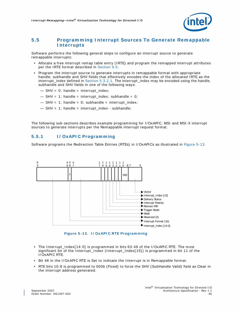
Intel® Virtualization Technology for Directed I/OSeptember 2007 Architecture Specification - Rev 1.1Order Number: D51397-003 45
Interrupt Remapping—Intel® Virtualization Technology for Directed I/O
5.5 Programming Interrupt Sources To Generate Remappable Interrupts
Software performs the following general steps to configure an interrupt source to generate remappable interrupts:
• Allocate a free interrupt remap table entry (IRTE) and program the remapped interrupt attributes per the IRTE format described in Section 9.5.
• Program the interrupt source to generate interrupts in remappable format with appropriate handle, subhandle and SHV fields that effectively encodes the index of the allocated IRTE as the interrupt_index defined in Section 5.3.2.1. The interrupt_index may be encoded using the handle, subhandle and SHV fields in one of the following ways:
— SHV = 0; handle = interrupt_index;
— SHV = 1; handle = interrupt_index; subhandle = 0;
— SHV = 1; handle = 0; subhandle = interrupt_index;
— SHV = 1; handle = interrupt_index - subhandle;
The following sub-sections describes example programming for I/OxAPIC, MSI and MSI-X interrupt sources to generate interrupts per the Remappable interrupt request format.
5.5.1 I/OxAPIC Programming
Software programs the Redirection Table Entries (RTEs) in I/OxAPICs as illustrated in Figure 5-13.
• The Interrupt_Index[14:0] is programmed in bits 63:49 of the I/OxAPIC RTE. The most significant bit of the Interrupt_Index (Interrupt_Index[15]) is programmed in bit 11 of the I/OxAPIC RTE.
• Bit 48 in the I/OxAPIC RTE is Set to indicate the Interrupt is in Remappable format.
• RTE bits 10:8 is programmed to 000b (Fixed) to force the SHV (SubHandle Valid) field as Clear in the interrupt address generated.
Figure 5-13. I/OxAPIC RTE Programming
Delivery Status
0
Interrupt_Index [15]
Trigger Mode
Vector
Mask
48
Remote IRR
63
Interrupt Polarity
7816
Reserved (0)
17
Interrupt_Index [14:0]
47
15
14
13
12
000
11
10
49
1
Interrupt Format (1b)
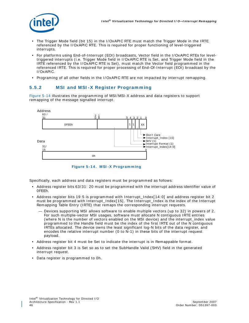
Intel® Virtualization Technology for Directed I/O—Interrupt Remapping
Intel® Virtualization Technology for Directed I/OArchitecture Specification - Rev 1.1 September 200746 Order Number: D51397-003
• The Trigger Mode field (bit 15) in the I/OxAPIC RTE must match the Trigger Mode in the IRTE referenced by the I/OxAPIC RTE. This is required for proper functioning of level-triggered interrupts.
• For platforms using End-of-Interrupt (EOI) broadcasts, Vector field in the I/OxAPIC RTEs for level-triggered interrupts (i.e. Trigger Mode field in I/OxAPIC RTE is Set, and Trigger Mode field in the IRTE referenced by the I/OxAPIC RTE is Set), must match the Vector field programmed in the referenced IRTE. This is required for proper processing of End-Of-Interrupt (EOI) broadcast by the I/OxAPIC.
• Programing of all other fields in the I/OxAPIC RTE are not impacted by interrupt remapping.
5.5.2 MSI and MSI-X Register Programming
Figure 5-14 illustrates the programming of MSI/MSI-X address and data registers to support remapping of the message signalled interrupt.
Specifically, each address and data registers must be programmed as follows:
• Address register bits 63/31: 20 must be programmed with the interrupt address identifier value of 0FEEh.
• Address register bits 19:5 is programmed with Interrupt_Index[14:0] and address register bit 2 must be programmed with Interrupt_Index[15]. The Interrupt_Index is the index of the Interrupt Remapping Table Entry (IRTE) that remaps the corresponding interrupt requests.
— Devices supporting MSI allows software to enable multiple vectors (up to 32) in powers of 2. For such multiple-vector MSI usages, software must allocate N contiguous IRTE entries (where N is the number of vectors enabled on the MSI device) and the interrupt_index value programmed to the Handle field must be the index of the first IRTE out of the N contiguous IRTEs allocated. The device owns the least significant log-N bits of the data register, and encodes the relative interrupt number (0 to N-1) in these bits of the interrupt request payload.
• Address register bit 4 must be Set to indicate the interrupt is in Remappable format.
• Address register bit 3 is Set so as to set the SubHandle Valid (SHV) field in the generated interrupt request.
• Data register is programmed to 0h.
Figure 5-14. MSI-X Programming
01219
20
XX
4 3
Don’t Care
0FEEh
63 /31
31/15
Address
Data
1
Interrupt Format (1)
0h
Interrupt_Index [15]SHV (1)
0Interrupt_index[14:0]
1
5

Intel® Virtualization Technology for Directed I/OSeptember 2007 Architecture Specification - Rev 1.1Order Number: D51397-003 47
Interrupt Remapping—Intel® Virtualization Technology for Directed I/O
5.6 Remapping Hardware - Interrupt Programming
Interrupts generated by the remapping hardware itself (Fault Event and Invalidation Completion Events) are not subject to interrupt remapping. The following sections describe the programming of the Fault Event and Invalidation Completion Event data/address registers on Intel®64 platforms and on ItaniumTM platforms.
5.6.1 Programming in Intel®64 xAPIC Mode
Figure 5-15. Remapping Hardware Interrupt Programming in Intel®64 xAPIC Mode
01219
20
XX
4 3
Red irec tion H in tD estina tion M odeD on ’t Ca re
D estina tion ID (AP IC ID 7 :0 )
31
Reserved (0 )
FEEh
11
12
031
0 h
Vecto rD e live ry M ode0: F ixed1: Low est P rio rity
78
Reserved (0 )
031
Reserved (0 )
D a ta R eg iste r
Add ress R eg iste r
U pper Add ress R eg iste r

Intel® Virtualization Technology for Directed I/O—Interrupt Remapping
Intel® Virtualization Technology for Directed I/OArchitecture Specification - Rev 1.1 September 200748 Order Number: D51397-003
5.6.2 Programming in Intel®64 x2APIC Mode1
1. Hardware support for x2APIC mode is reported through the EIM field in the Extended Capability Register. x2APIC mode is enabled through the Interrupt Remapping Table Address Register.
Figure 5-16. Remapping Hardware Interrupt Programming in Intel®64 x2APIC Mode
01219
20
XX
4 3
Red irec tion H in tD estina tion M odeD on ’t Ca re
D estina tion ID (AP IC ID 7 :0 )
31
Reserved (0 )
FEEh
11
12
031
0 h
Vecto rD e live ry M ode0: F ixed1: Low est P rio rity
78
Reserved (0 )
031
Reserved (0 )
D a ta R eg iste r
Add ress R eg iste r
U pper Add ress R eg iste r
78
D estina tion ID (A PIC ID 31 :8 )

Intel® Virtualization Technology for Directed I/OSeptember 2007 Architecture Specification - Rev 1.1Order Number: D51397-003 49
Interrupt Remapping—Intel® Virtualization Technology for Directed I/O
5.6.3 Programming on ItaniumTM Platforms
5.7 Handling of Platform Events
Platforms supporting interrupt remapping are highly recommended to use side-band mechanisms (such as dedicated pins between chipset/board-logic and CPU), or in-band methods (such as platform/vendor defined messages) to deliver platforms events such as SMI/PMI/NMI/INIT/MCA. This is to avoid the dependence on system software to deliver these critical platform events.
Some existing platforms are known to use I/OxAPIC RTEs (Redirection Table Entries) to deliver SMI, PMI and NMI events. There are at least two existing initialization approaches for such platform events delivered through I/OxAPIC RTEs.
• Some existing platforms report to system software the I/OxAPIC RTEs connected to platform event sources through ACPI, enabling system software to explicitly program/enable these RTEs. Examples for this include, the 'NMI Source Reporting' structure in ACPI MADT (for reporting NMI source), and 'Platform Interrupt Source' structure in ACPI MADT (for reporting PMI source in ItaniumTM platforms).
• Alternatively, some existing platforms program the I/OxAPIC RTEs connected to specific platform event sources during BIOS initialization, and depend on system software to explicitly preserve these RTEs in the BIOS initialized state. (For example, some platforms are known to program specific I/OxAPIC RTE for SMI generation through BIOS before handing control to system
Figure 5-17. Remapping Hardware Interrupt Programming on ItaniumTM
01219
20
XX
4 3
Red irection H in tD estina tion M odeD on ’t Care
D est. ID
31
Ext. D est. ID
FEEh
11
12
031
0 h
Vecto rD e live ry M ode
78
Reserved (0 )
031
Reserved (0 )
D a ta Reg iste r
Add ress Reg iste r
U pper Address Reg iste r

Intel® Virtualization Technology for Directed I/O—Interrupt Remapping
Intel® Virtualization Technology for Directed I/OArchitecture Specification - Rev 1.1 September 200750 Order Number: D51397-003
software, and depend on system software preserving the RTEs pre-programmed with SMI delivery mode).
On platforms supporting interrupt-remapping, delivery of SMI, PMI and NMI events through I/OxAPIC RTEs require system software programming the respective RTEs to be properly remapped through the Interrupt Remapping Table. To avoid this management burden on system software, platforms supporting interrupt remapping are highly recommended to avoid delivering platform events through I/OxAPIC RTEs, and instead deliver them through dedicated pins (such as the processor’s xAPIC LINTn input) or through alternative platform-specific messages.

Intel® Virtualization Technology for Directed I/OSeptember 2007 Architecture Specification - Rev 1.1Order Number: D51397-003 51
Hardware Caching Details—Intel® Virtualization Technology for Directed I/O
6 Hardware Caching Details
This chapter describes the architectural behavior associated with the following hardware caches and the associated invalidation operations:
• Context-cache
• IOTLB and PDE (Page Directory Entry) Cache
• Interrupt Entry Cache (IEC)
• Device-IOTLB
6.1 Caching Mode
The Caching Mode (CM) field in Capability register indicates if the underlying implementation caches not-present and erroneous entries. When the CM field is reported as Set, any software updates to the remapping structures (including updates to not-present entries) requires explicit invalidation of the caches.
Hardware implementations of this architecture must support operation corresponding to CM=0. Operation corresponding to CM=1 may be supported by software implementations (emulation) of this architecture for efficient virtualization. DMA-remapping software drivers should be written to handle both caching modes.
Software implementations virtualizing the remapping architecture (such as a VMM emulating remapping hardware to an operating system running within a guest partition) may report CM=1 to efficiently virtualize the hardware. Software virtualization typically requires the remapping structures to be shadowed in software. Reporting the Caching Mode as Set for the virtual hardware requires the guest software to explicitly issue invalidation operations on the virtual hardware for any/all updates to the guest remapping structures. The virtualizing software may trap these virtual invalidation operations to keep the shadow tables consistent to any guest structure modifications, without resorting to other less efficient techniques (such as write-protecting the guest structures through processor page-tables).
6.1.1 Context Caching
For implementations reporting Caching Mode (CM) as Clear in the Capability register, if any of the following fault conditions are encountered as part of accessing a root-entry or a context-entry, the resulting entry is not cached in the context-cache.
• Attempt to access the root table through the RTA field in the Root-entry Table Address register resulted in error.
• Present (P) field of the root-entry is Clear.
• Invalid programming of one or more fields in the present root-entry.
• Attempt to access a context-entry table through the Context Table Pointer (CTP) field in the present root-entry resulted in error.
• Present (P) field of the context-entry is Clear.
• Invalid programming of one or more fields in the present context-entry.
• One or more non-zero reserved fields in the present root-entry or context-entry.

Intel® Virtualization Technology for Directed I/O—Hardware Caching Details
Intel® Virtualization Technology for Directed I/OArchitecture Specification - Rev 1.1 September 200752 Order Number: D51397-003
For implementations reporting Caching Mode (CM) as Set in the Capability register, above conditions may cause caching of the entry that resulted in the fault1.
Since information from the present context-entries (such as domain-id) may be utilized to tag the IOTLB and the page-directory caches, to ensure the updates are visible to hardware, software must invalidate the IOTLB (domain-selectively or globally) after the context-cache invalidation is completed.
6.1.2 IOTLB Caching
IOTLB caches effective translations for a given DMA address, including the cumulative Read and Write permissions from the page-walk leading to this translation.
For implementations reporting Caching Mode (CM) as Clear in the Capability register, IOTLB caches only valid mappings (i.e. results of successful page-walks with effective translations that has at least one of the cumulative Read and Write permissions from the page-walk being Set). Specifically, if any of the following conditions are encountered, the results are not cached in the IOTLB:
• Conditions listed in Section 6.1.1.
• Attempt to access the page directory/table through the ASR field in the context-entry or the ADDR field of the previous page-directory entry in the page walk resulted in error.
• Read (R) and Write (W) fields of a page directory/table entry encountered in a page-walk is Clear (not-present entry).
• Invalid programming of one or more fields in the present page directory/table entry.
• One or more non-zero reserved fields in the present page directory/table entry.
• The cumulative read and write permissions from the page-walk was both Clear (effectively not-present entry).
For implementations reporting Caching Mode (CM) as Set in the Capability register, above conditions may cause caching of erroneous or not-present mappings in the IOTLB.
6.1.3 Page Directory Entry (PDE) Caching
Support for PDE caching is implementation dependent, and transparent to software (except for the Invalidation Hint (IH) in IOTLB invalidation command).
• For implementations reporting Caching Mode (CM) as Clear in the Capability register, if any of the following fault conditions are encountered as part of accessing a page-directory entry, the resulting entry is not cached in the non-leaf cache.
• Attempt to access the page-directory through either the ASR field of context-entry (in case of root page directory), or the ADDR field of the previous page directory entry in the page-walk resulted in error.
• Read (R) and Write (W) fields of the page-directory entry is Clear (not present entry).
• Invalid programming of one ore more fields in the present page directory entry.
• One or more non-zero reserved fields in the present page directory entry.
For implementations reporting Caching Mode (CM) as Set in the Capability register, above conditions may cause caching of the corresponding page-directory entries.
6.1.4 Interrupt Entry Caching
Implementations supporting interrupt remapping may cache frequently used interrupt remapping table entries in the Interrupt Entry Cache (IEC).
1. If a fault was detected without a present context-entry, the reserved domain-id value of 0 is used to tag the cached faulting entry.
Intel® Virtualization Technology for Directed I/OSeptember 2007 Architecture Specification - Rev 1.1Order Number: D51397-003 53
Hardware Caching Details—Intel® Virtualization Technology for Directed I/O
For implementations reporting Caching Mode (CM) as Clear in the Capability register, if any of the interrupt-remapping fault conditions described in Section 5.3.3.1 is encountered, the resulting entry is not cached in the IEC.
For implementations reporting Caching Mode (CM) as Set in the Capability register, interrupt-remapping fault conditions may cause caching of the corresponding interrupt remapping entries.
6.2 Cache Invalidations
For software to invalidate the various caching structures, the architecture supports the following two types of invalidation interfaces:
• Register based invalidation interface
• Queued invalidation interface
All hardware implementations are required to support the register based invalidation interface. Implementations report the queued invalidation support through the Extended Capability Register.
The following sections provides more details on these hardware interfaces.
6.2.1 Register Based Invalidation Interface
The register based invalidations provides a synchronous hardware interface for invalidations. Software is expected to write to the IOTLB registers to submit invalidation command and may poll on these registers to check for invalidation completion. For optimal performance, hardware implementations are recommended to complete an invalidation request with minimal latency.
The following sub-sections describe the invalidation command registers. Hardware implementations must handle commands through these registers irrespective of remapping hardware enable status (i.e irrespective of TES and IES status in the Global Status register).
6.2.1.1 Context Command Register:
Context command register supports invalidating the context cache. The architecture defines the following types of context-cache invalidation requests. Hardware implementations may perform the actual invalidation at a coarser granularity if the requested invalidation granularity is not supported.
• Global Invalidation: All context-cache entries cached at a remapping hardware unit are invalidated through a global invalidate.
• Domain-Selective Invalidation: Context-cache entries corresponding to a specific domain (specified by the domain-id) are invalidated through a domain-selective invalidate.
• Device-Selective Invalidation: Context-cache entries corresponding to a specific device within a domain are invalidated through a device-selective invalidate.
When modifying root or context entries referenced by more than one remapping hardware units in a platform, software is responsible to explicitly invalidate the context-cache at each of these hardware units.
6.2.1.2 IOTLB Registers
IOTLB invalidation is supported through two 64-bit registers; (a) IOTLB Invalidate register and (b) Invalidation Address register. The architecture defines the following types of IOTLB invalidation requests. Hardware implementations may perform the actual invalidation at a coarser granularity if the requested invalidation granularity is not supported.
• Global Invalidation: All entries in the IOTLB are invalidated through a global invalidate.
• Domain-Selective Invalidation: Entries in the IOTLB that corresponds to a specific domain (specified by the domain-id) are invalidated through a domain-selective invalidate.

Intel® Virtualization Technology for Directed I/O—Hardware Caching Details
Intel® Virtualization Technology for Directed I/OArchitecture Specification - Rev 1.1 September 200754 Order Number: D51397-003
• Page-Selective Invalidation: Entries in the IOTLB that corresponds to the specified DMA address(es) of a domain are invalidated through a page-selective invalidate.
When modifying page-table entries referenced by more than one remapping hardware units in a platform, software is responsible to explicitly invalidate the IOTLB at each of these hardware units.
Hardware implementations supporting PDE (non-leaf) caching functions as follows:
• Globally invalidate the PDE-caches on IOTLB global invalidations.
• Domain-selective (or global) invalidation of PDE-caches on IOTLB domain-selective invalidations.
• For IOTLB page-selective invalidations with Invalidation Hint (IH) field Set, hardware implementations are recommended to preserve the cached PDEs.
• For IOTLB page-selective invalidations with IH field Clear, hardware must invalidate the appropriate PDE-cache entries. This may be achieved by invalidating only the cached PDEs corresponding to the mappings specified in the Invalidation Address registers, or through a domain-selective (or global) invalidation of the PDE caches. The actual invalidation granularity reported by hardware in the IOTLB Invalidate register is always the granularity at which the invalidation was performed on the IOTLB.
6.2.2 Queued Invalidation Interface
The queued invalidation provides an advanced interface for software to submit invalidation requests to hardware and to synchronize invalidation completions with hardware. Hardware implementations report queued invalidation support through the Extended Capability register.
The queued invalidations is expected to be most beneficial for the following software usages:
• Usages that frequently map and un-map I/O buffers in the remapping page-tables (causing frequent invalidations).
• Usages where page-selective operation requests frequently span pages that are not virtually contiguous.
• Usages where software can overlap processing with invalidations. (i.e., Usages where software does not always block while an invalidation operation is pending in hardware).
• Invalidation operations that are latency prone (such as invalidating Device-IOTLBs on a device across the PCI Express interconnect).
• Usages of VMM virtualizing remapping hardware, where VMM may improve the virtualization performance by allowing guests to queue invalidation requests (instead of intercepting guest MMIO accesses for each invalidation request as required by the register based interface).
The queued invalidation interface uses a Invalidation Queue (IQ) which is a circular buffer in system memory. Software submits commands by writing Invalidation Descriptors to the IQ. The following registers are defined to configure and manage the IQ:
• Invalidation Queue Address Register: Software programs this register to configure the base address and size of the contiguous memory region in system memory hosting the Invalidation Queue.
• Invalidation Queue Head Register: This register points to the invalidation descriptor in the IQ that hardware will process next. The Invalidation Queue Head register is incremented by hardware after fetching a valid descriptor from the IQ. Hardware interprets the IQ as empty when the head and tail registers are equal.
• Invalidation Queue Tail Register: This register points to the invalidation descriptor in the IQ to be written next by software. Software increments this register after writing one or more invalidation descriptors to the IQ.

Intel® Virtualization Technology for Directed I/OSeptember 2007 Architecture Specification - Rev 1.1Order Number: D51397-003 55
Hardware Caching Details—Intel® Virtualization Technology for Directed I/O
To enable queued invalidations, software must:
• Ensure all invalidation requests submitted to hardware through the IOTLB registers are completed. (i.e. no pending invalidation requests in hardware).
• Setup the IQ address and size through the Invalidation Queue Address register.
• Enable the queued invalidation interface through the Global Command register. When enabled, hardware sets the QIES field in the Global Status register.
When the queued invalidation is enabled, software must submit invalidation commands only through the IQ (and not through any invalidation command registers).
Hardware fetches descriptors from the IQ in FIFO order starting from the Head register whenever all of the following conditions are true. This is independent of the remap hardware enable status (state of TES and IES fields in Global Status Register).
• QIES field in the Global Status register is Set (indicating queued invalidation is enabled)
• IQ is not empty (i.e. Head and Tail pointer registers are not equal)
• There is no pending Invalidation Queue Error or Invalidation Time-out Error (IQE and ITE fields in the Fault Status Register are both Clear)
Hardware implementations may fetch one or more descriptors together. However, hardware must increment the Invalidation Queue Head register only after verifying the fetched descriptor to be valid. Hardware handling of invalidation queue errors are described in Section 6.2.2.7.
Once enabled, to disable the queued invalidation interface, software must:
• Quiesce the invalidation queue. The invalidation queue is considered quiesced when the queue is empty (head and tail registers equal) and the last descriptor completed is an Invalidation Wait Descriptor (which indicates no invalidation requests are pending in hardware).
• Disable queued invalidation. The queued invalidation interface is disabled through the Global Command register. When disabled, hardware clears the QIES field in the Global Status Register.
The following subsections describe the various Invalidation Descriptors. All descriptors are 128-bit sized. Type field (bits 3:0) of each descriptor identifies the descriptor type. Software must program the reserved fields in the descriptors as zero.
6.2.2.1 Context Cache Invalidate Descriptor
The Context Cache Invalidate Descriptor (cc_inv_dsc) allows software to invalidate the context cache. The descriptor includes the following parameters:
Figure 6-18. Context Cache Invalidate Descriptor
01hSource-ID Domain-IDFM
0
G
Rsvd
RsvdRsvd
31 456
15
16
47
48
49
50
63
32
127
64
3

Intel® Virtualization Technology for Directed I/O—Hardware Caching Details
Intel® Virtualization Technology for Directed I/OArchitecture Specification - Rev 1.1 September 200756 Order Number: D51397-003
• Granularity (G): The G field indicates the requested invalidation granularity. The encoding of the G field is same as the CIRG field in the Context Command register (described in Section 10.4.7). Hardware implementations may perform coarser invalidation than the granularity requested.
• Domain-ID (DID): For domain-selective and device-selective invalidations, the DID field indicates the target domain-id.
• Source-ID (SID): For device-selective invalidations, the SID field indicates the target device-id.
• Function Mask (FM): The Function Mask field indicates the bits of the SID field to be masked for device-selective invalidations. The usage and encoding of the FM field is same as the FM field encoding in the Context Command register.
Hardware implementations reporting a write-buffer flushing requirement (RWBF=1 in Capability register) must implicitly perform a write buffer flushing before invalidating the context-cache. Refer to Section 11.1 for write buffer flushing requirements.
Since information from the context-cache may be used to tag the IOTLB, software must always follow a context-cache invalidation with an IOTLB invalidation.
6.2.2.2 IOTLB Invalidate Descriptor
The IOTLB Invalidate Descriptor (iotlb_inv_dsc) allows software to invalidate the IOTLB and PDE-cache. The descriptor includes the following parameters:
• Granularity (G): The G field indicates the requested invalidation granularity (global, domain-selective or page-selective). The encoding of the G field is same as the IIRG field in the IOTLB Invalidate register (described in Section 10.4.8). Hardware implementations may perform coarser invalidation than the granularity requested.
• Drain Reads (DR): Software sets this flag to indicate hardware must drain DMA read requests that are already processed by the remapping hardware, but queued within the Root-Complex to be completed. When this flag is Set, hardware must perform the DMA read drain before the next Invalidation Wait Descriptor (described in Section 6.2.2.5) is completed. Section 6.3 describes hardware support for DMA draining.
• Drain Writes (DW): Software sets this flag to indicate hardware must drain relevant DMA write requests that are already processed by the remapping hardware, but queued within the Root-Complex to be completed. When this flag is Set, hardware must drain the relevant DMA writes before the next Invalidation Wait Descriptor is completed. Section 6.3 describes hardware support for DMA draining.
• Domain-ID (DID): For domain-selective and page-selective invalidations, the DID field indicates the target domain-id. This field is ignored by hardware for global invalidations.
• Invalidation Hint (IH): For page-selective invalidations, the Invalidation Hint specifies if the corresponding entries in the PDE-cache needs to be invalidated or not. For software usages that updates only the leaf PTEs, the PDE-cache can be preserved by specifying the Invalidation Hint.
Figure 6-19. IOTLB Invalidate Descriptor
02hDID
0
GRsvdRsvd
31 456
15
16
63
32
127
64
3
ADDR [63:12] IH AM
69
70
71
Rsvd
75
76
78DR
DW
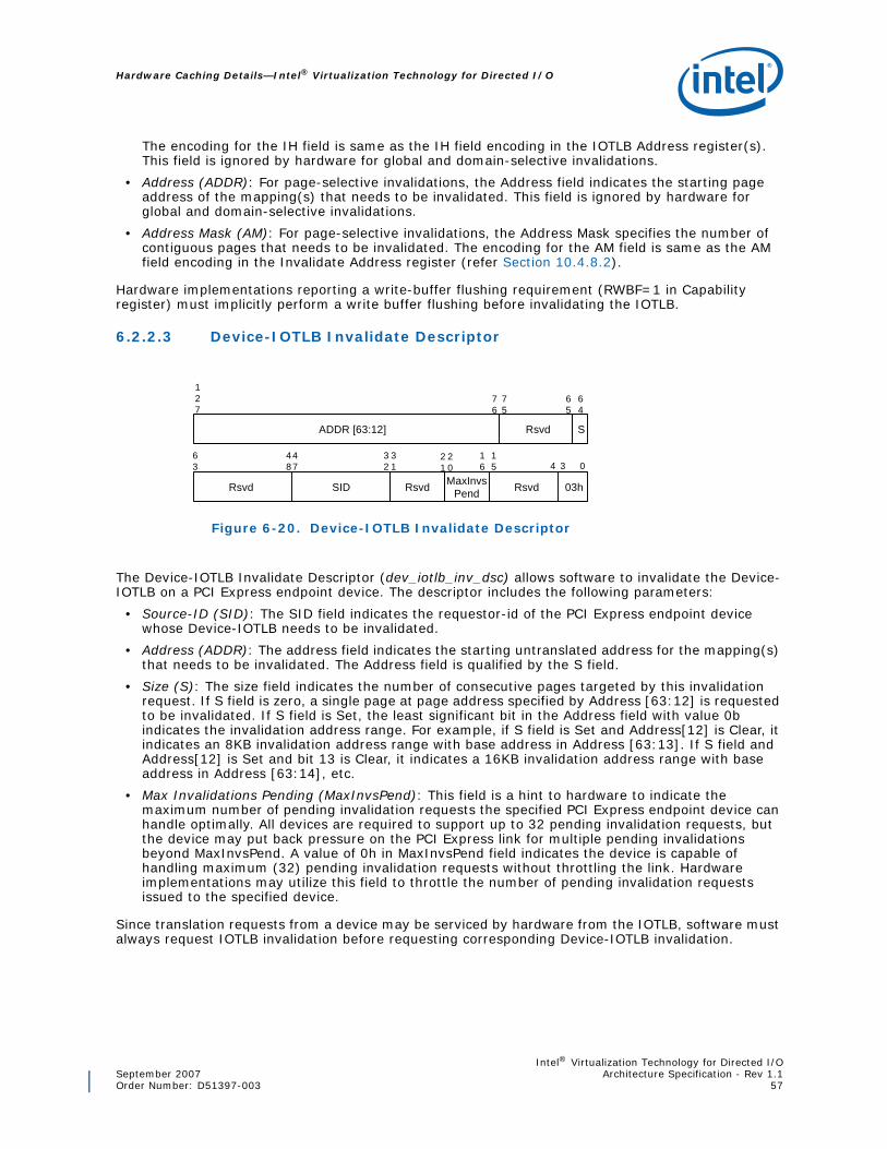
Intel® Virtualization Technology for Directed I/OSeptember 2007 Architecture Specification - Rev 1.1Order Number: D51397-003 57
Hardware Caching Details—Intel® Virtualization Technology for Directed I/O
The encoding for the IH field is same as the IH field encoding in the IOTLB Address register(s). This field is ignored by hardware for global and domain-selective invalidations.
• Address (ADDR): For page-selective invalidations, the Address field indicates the starting page address of the mapping(s) that needs to be invalidated. This field is ignored by hardware for global and domain-selective invalidations.
• Address Mask (AM): For page-selective invalidations, the Address Mask specifies the number of contiguous pages that needs to be invalidated. The encoding for the AM field is same as the AM field encoding in the Invalidate Address register (refer Section 10.4.8.2).
Hardware implementations reporting a write-buffer flushing requirement (RWBF=1 in Capability register) must implicitly perform a write buffer flushing before invalidating the IOTLB.
6.2.2.3 Device-IOTLB Invalidate Descriptor
The Device-IOTLB Invalidate Descriptor (dev_iotlb_inv_dsc) allows software to invalidate the Device-IOTLB on a PCI Express endpoint device. The descriptor includes the following parameters:
• Source-ID (SID): The SID field indicates the requestor-id of the PCI Express endpoint device whose Device-IOTLB needs to be invalidated.
• Address (ADDR): The address field indicates the starting untranslated address for the mapping(s) that needs to be invalidated. The Address field is qualified by the S field.
• Size (S): The size field indicates the number of consecutive pages targeted by this invalidation request. If S field is zero, a single page at page address specified by Address [63:12] is requested to be invalidated. If S field is Set, the least significant bit in the Address field with value 0b indicates the invalidation address range. For example, if S field is Set and Address[12] is Clear, it indicates an 8KB invalidation address range with base address in Address [63:13]. If S field and Address[12] is Set and bit 13 is Clear, it indicates a 16KB invalidation address range with base address in Address [63:14], etc.
• Max Invalidations Pending (MaxInvsPend): This field is a hint to hardware to indicate the maximum number of pending invalidation requests the specified PCI Express endpoint device can handle optimally. All devices are required to support up to 32 pending invalidation requests, but the device may put back pressure on the PCI Express link for multiple pending invalidations beyond MaxInvsPend. A value of 0h in MaxInvsPend field indicates the device is capable of handling maximum (32) pending invalidation requests without throttling the link. Hardware implementations may utilize this field to throttle the number of pending invalidation requests issued to the specified device.
Since translation requests from a device may be serviced by hardware from the IOTLB, software must always request IOTLB invalidation before requesting corresponding Device-IOTLB invalidation.
Figure 6-20. Device-IOTLB Invalidate Descriptor
03hSID
0
Rsvd
31 4
15
16
47
63
32
127
64
3
ADDR [63:12] S
65
75
Rsvd
76
MaxInvsPend
20
Rsvd
21
Rsvd
48

Intel® Virtualization Technology for Directed I/O—Hardware Caching Details
Intel® Virtualization Technology for Directed I/OArchitecture Specification - Rev 1.1 September 200758 Order Number: D51397-003
6.2.2.4 Interrupt Entry Cache Invalidate Descriptor
The Interrupt Entry Cache Invalidate Descriptor (iec_inv_dsc) allows software to invalidate the Interrupt Entry Cache. The descriptor includes the following parameters:
• Granularity (G): This field indicates the granularity of the invalidation request. If Clear, a global invalidation of the interrupt-remapping cache is requested. If Set, a index-selective invalidation is requested.
• Interrupt Index (IIDX): This field specifies the index of the interrupt remapping entry that needs to be invalidated through a index-selective invalidation.
• Index Mask (IM): For index-selective invalidations, the index-mask specifies the number of contiguous interrupt indexes that needs to be invalidated. The encoding for the IM field is described below in Table 10).
As part of IEC invalidation, hardware must drain interrupt requests that are already processed by the remapping hardware, but queued within the Root-Complex to be delivered to the processor. Section 6.4 describes hardware support for interrupt draining.
Hardware implementations reporting a write-buffer flushing requirement (RWBF=1 in Capability register) must implicitly perform a write buffer flushing before invalidating the Interrupt Entry Cache.
Figure 6-21. Interrupt Entry Cache Invalidate Descriptor
Table 10. Index Mask Programming
Index Mask Value
Index bits Masked
Mappings Invalidated
0 None 1
1 0 2
2 1:0 4
3 2:0 8
4 3:0 16
... ... ...
04hIIDX
0
G
Rsvd
RsvdRsvd
31 45
63
32
127
64
347
48
IM
27
26

Intel® Virtualization Technology for Directed I/OSeptember 2007 Architecture Specification - Rev 1.1Order Number: D51397-003 59
Hardware Caching Details—Intel® Virtualization Technology for Directed I/O
6.2.2.5 Invalidation Wait Descriptor
The Invalidation Wait Descriptor (inv_wait_dsc) descriptor allows software to synchronize with hardware for the invalidation request descriptors submitted before the wait descriptor. The descriptor includes the following parameters:
• Status Write (SW): Indicate the invalidation wait descriptor completion by performing a coherent DWORD write of the value in the Status Data field to the address specified in the Status Address field.
• Status Address and Data: Status address and data is used by hardware to perform wait descriptor completion status write when the SW field is Set. Hardware behavior is undefined if the Status Address specified is not an address route-able to memory (such as peer address, interrupt address range of 0xFEEX_XXXX etc.). The Status Address and Data fields are ignored by hardware when the Status Write (SW) field is Clear.
• Interrupt Flag (IF): Indicate the invalidation wait descriptor completion by generating an invalidation completion event per the programming of the Invalidation Completion Event registers. Section 6.2.2.6 describes details on invalidation event generation.
• Fence Flag (FN): Indicate descriptors following the invalidation wait descriptor must be processed by hardware only after the invalidation wait descriptor completes.
Section 6.2.2.8 describes queued invalidation ordering considerations. Hardware completes an invalidation wait command as follows:
• If a status write is specified in the wait descriptor (SW=1), hardware performs a coherent write of the status data to the status address.
• If an interrupt is requested in the wait descriptor (IF=1), hardware sets the IWC field in the Invalidation Completion Status register. An invalidation completion interrupt may be generated as described in the following section.
6.2.2.6 Hardware Generation of Invalidation Completion Events
The invalidation event interrupt generation logic functions as follows:
• At the time hardware sets the IWC field, it checks if the IWC field is already Set to determine if there is a previously reported invalidation completion interrupt condition that is yet to be serviced by software. If IWC field is already Set, the invalidation event interrupt is not generated.
• If the IWC field is not already Set, the Interrupt Pending (IP) field in the Invalidation Event Control register is Set. The Interrupt Mask (IM) field is then checked and one of the following conditions is applied:
— If IM field is Clear, the fault event is generated along with clearing the IP field.
Figure 6-22. Invalidation Wait Descriptor
05h
0
Status Address [63:2]
IF
31 45
63
32
127
64
3
Status Data SW
6
65
66
Rsvd
Rsvd
7FN

Intel® Virtualization Technology for Directed I/O—Hardware Caching Details
Intel® Virtualization Technology for Directed I/OArchitecture Specification - Rev 1.1 September 200760 Order Number: D51397-003
— If IM field is Set, the interrupt is not generated.
The following logic applies for interrupts held pending by hardware in the IP field:
• If IP field was Set when software clears the IM field, the fault event interrupt is generated along with clearing the IP field.
• If IP field was Set when software services the pending interrupt condition (indicated by IWC field in the Invalidation Completion Status register being Clear), the IP field is cleared.
The invalidation completion event interrupt must push any in-flight invalidation completion status writes, including status writes that may have originated from the same inv_wait_dsc for which the interrupt was generated. Similarly, read completions due to software reading any of the remapping hardware registers must push (commit) any in-flight invalidation completion event interrupts and status writes generated by the respective hardware unit.
The invalidation completion event interrupts are never subject to interrupt remapping.
6.2.2.7 Hardware Handling of Queued Invalidation Interface Errors
Hardware handles the various queued invalidation interface error conditions as follows:
• Invalidation Queue Errors: If hardware detects an invalid Tail pointer at the time of fetching a descriptor, or detects an error when fetching a descriptor from the invalidation queue, or detects that the fetched descriptor fetched is invalid, hardware sets the IQE (Invalidation Queue Error) field in the Fault Status register. A fault event may be generated based on the programming of the Fault Event Control register. The Head pointer register is not incremented, and references the descriptor associated with the queue error. No new descriptors are fetched from the Invalidation Queue until software clears the IQE field in the Fault Status register. Tail pointer register updates by software while the IQE field is Set does not cause descriptor fetches by hardware. Any invalidation commands ahead of the invalid descriptor that are already fetched and pending in hardware at the time of detecting the invalid descriptor error are completed by hardware as normal.
• Invalid Device-IOTLB Invalidation Response: If hardware receives an invalid Device-IOTLB invalidation response, hardware sets the Invalidation Completion Error (ICE) field in the Fault Status register. A fault event may be generated based on the programming of the Fault Event Control register. Hardware continues with processing of descriptors from the Invalidation Queue as normal.
• Device-IOTLB Invalidation Response Time-out: If hardware detects a Device-IOTLB invalidation response time-out, hardware frees the corresponding ITag and sets the ITE (Invalidation Time-out Error) field in the Fault Status register. A fault event may be generated based on the programming of the Fault Event Control register. No new descriptors are fetched from the Invalidation Queue until software clears the ITE field in the Fault Status register. Tail pointer register updates by software while the ITE field is Set does not cause descriptor fetches by hardware. At the time ITE field is Set, hardware aborts any inv_wait_dsc commands pending in hardware. Any invalidation responses received while ITE field is Set are processed as normal (as described in Section 4.2). Since the time-out could be for any (one or more) of the pending dev_iotlb_inv_dsc commands, execution of all descriptors including and behind the oldest pending dev_iotlb_inv_dsc is not guaranteed.
6.2.2.8 Queued Invalidation Ordering Considerations
Hardware must support the following ordering considerations when processing descriptors fetched from the invalidation queue:
• Hardware must execute an IOTLB Invalidation Descriptor (iotlb_inv_dsc) only after all Context Cache Invalidation Descriptors (cc_inv_dsc) ahead of it in the Invalidation Queue are completed.
• Hardware must execute a Device-IOTLB Invalidation Descriptor (dev_iotlb_inv_dsc) only after all IOTLB Invalidation Descriptors (iotlb_inv_dsc) and Interrupt Entry Cache Invalidation Descriptors (iec_inv_dsc) ahead of it in the Invalidation Queue are completed.

Intel® Virtualization Technology for Directed I/OSeptember 2007 Architecture Specification - Rev 1.1Order Number: D51397-003 61
Hardware Caching Details—Intel® Virtualization Technology for Directed I/O
• Hardware must report completion of an Invalidation Wait Descriptor (inv_wait_dsc) only after at least all the descriptors ahead of it in the Invalidation Queue and behind the previous inv_wait_dsc are completed.
• If the Fence (FN) flag is Clear in a inv_wait_dsc, hardware may execute descriptors following the inv_wait_dsc before the wait command is completed. If the Fence (FN) flag is Set in a inv_wait_dsc, hardware must execute descriptors following the inv_wait_dsc only after the wait command is completed.
• When a Device-IOTLB invalidation time-out is detected, hardware must not complete any pending inv_wait_dsc commands.
6.3 DMA Draining
DMA requests that are already processed by the remapping hardware, but queued within the Root-Complex to be completed are referred as non-committed DMA requests. DMA draining refers to hardware pushing (committing) these DMA requests to the global ordering point. Hardware implementations report support for DMA draining through the Capability registers.
A DMA write request to system memory is considered drained when the effects of the write are visible to processor accesses to addresses targeted by the DMA write request. A DMA read request to system memory is considered drained when the Root-Complex has finished fetching all of its read response data from memory.
Requirements for DMA draining are described below:
• DMA draining applies only to requests to memory and do not guarantee draining of requests to peer destinations.
• DMA draining applies only for untranslated requests (AT=00b), including those processed as pass-through (Context-entry specifying Translation Type as 10b) by the remapping hardware.
• Draining of translated DMA requests (AT=10b) requires issuing an Device-IOTLB invalidation command to the endpoint device. Endpoint devices supporting Address Translation Services (ATS) are required to wait for pending translated read responses (or keep track of pending translated read requests and discard their read responses when they arrive) before issuing the ATS invalidation completion message. This effectively guarantees DMA read draining of translated requests. The ATS invalidation completion message is issued on the posted channel and pushes all writes from the device (including any translated writes) ahead of it. To ensure proper write draining of translated requests, remapping hardware must process ATS invalidation completion messages per the PCI Express ordering rules (i.e., after processing all posted requests ahead of it).
• Read and write draining of untranslated DMA requests are required when DMA-remapping hardware status changes from disabled to enabled. The draining must be completed before hardware sets the TES field in Global Status register (which indicates DMA remap hardware enabled). Hardware implementations may perform draining of untranslated DMA requests when remapping hardware status changes from enabled to disabled.
• Read and write draining of untranslated DMA requests are performed on IOTLB invalidation requests specifying Drain Read (DR) and Drain Write (DW) flags respectively. For IOTLB invalidations submitted through the IOTLB Invalidate register (IOTLB_REG), DMA draining must be completed before hardware clears the IVT field in the register (which indicates invalidation completed). For IOTLB invalidations submitted through the queued invalidation interface, DMA draining must be completed before the next Invalidation Wait Descriptor (inv_wait_dsc) is completed by hardware.
— For global IOTLB invalidation requests specifying DMA read/write draining, all non-committed DMA read/write requests queued within the Root-Complex are drained.
— For domain-selective IOTLB invalidation requests specifying DMA read/write draining, hardware only guarantees draining of non-committed DMA read/write requests to the domain specified in the invalidation request.

Intel® Virtualization Technology for Directed I/O—Hardware Caching Details
Intel® Virtualization Technology for Directed I/OArchitecture Specification - Rev 1.1 September 200762 Order Number: D51397-003
— For page-selective IOTLB invalidation requests specifying DMA read/write draining, hardware only guarantees draining of non-committed DMA read/write requests with untranslated address overlapping the address range specified in the invalidation request and to the specified domain.
6.4 Interrupt Draining
Interrupt requests that are already processed by the remapping hardware, but queued within the Root-Complex to be completed are referred as non-committed interrupt requests. Interrupt draining refers to hardware pushing (committing) these interrupt requests to the appropriate processor’s interrupt controller (Local xAPIC). An interrupt request is considered drained when the interrupt is accepted by the processor Local xAPIC (for fixed and lowest priority delivery mode interrupts this means the interrupt is at least recorded in the Local xAPIC Interrupt Request Register (IRR)).
Requirements for interrupt draining are described below:
• Interrupt draining applies to all non-committed interrupt requests, including Compatibility format interrupt requests processed as pass-through on Intel®64 platforms.
• Interrupt draining is required when interrupt-remapping hardware status changes from disabled to enabled. The draining must be completed before hardware sets the IES field in Global Status register (indicating interrupt-remapping hardware is enabled). Hardware implementations may perform interrupt draining when interrupt-remapping hardware status changes from enabled to disabled.
• Interrupt draining is performed on Interrupt Entry Cache (IEC) invalidation requests. For IEC invalidations submitted through the queued invalidation interface, interrupt draining must be completed before the next Invalidation Wait Descriptor is completed by hardware.
— For global IEC invalidation requests, all non-committed interrupt requests queued within the Root-Complex are drained.
— For index-selective IEC invalidation requests, hardware only guarantees draining of non-committed interrupt requests referencing interrupt indexes specified in the invalidation request.
• The Root-Complex considers an interrupt request as drained when it receives acknowledgement from the processor complex. Interrupt draining requires processor complex to ensure the interrupt request received is accepted by the Local xAPIC (for fixed interrupts, at least recorded in the IRR) before acknowledging the request to the Root-Complex.

Intel® Virtualization Technology for Directed I/OSeptember 2007 Architecture Specification - Rev 1.1Order Number: D51397-003 63
Hardware Fault Handling Details—Intel® Virtualization Technology for Directed I/O
7 Hardware Fault Handling Details
This section describes the hardware handling of various fault conditions.
7.1 Fault Categories
The fault conditions are broadly categorized as follows:
• DMA-remapping Faults: Error conditions detected when remapping DMA requests are handled as DMA-remapping faults. Table 3, Table 4 and Table 6 described the fault conditions related to untranslated, translation request and translated DMA processing respectively.
• Interrupt-remapping Faults: Error conditions detected when remapping interrupt requests are handled as interrupt-remapping faults. Table 9 described the fault conditions related to interrupt remapping.
7.2 Fault Logging
Faults are processed by logging the fault information and reporting the faults to software through a fault event (interrupt). The architecture defines two types of fault logging facilities: (a) Primary Fault Logging, and (b) Advanced Fault Logging. The primary fault logging method must be supported by all implementations of this architecture. Support for advanced fault logging is optional. Software must not change the fault logging method while hardware is enabled (TES or IRES fields Set in Global Status register).
7.2.1 Primary Fault Logging
The primary method for logging faults is through Fault Recording registers. The number of Fault Recording registers supported is reported through the Capability register. Chapter 10 describes the various Fault registers.
Hardware maintains an internal index to reference the Fault Recording register in which the next fault can be recorded. The index is reset to zero when both DMA and interrupt remapping is disabled (TES and IES fields Clear in Global Status register), and increments whenever a fault is recorded in a Fault Recording register. The index wraps around from N-1 to 0, where N is the number of fault recording registers supported by the remapping hardware unit.
Hardware maintains the Primary Pending Fault (PPF) field in the Fault Status register as the logical “OR” of the Fault (F) fields across all the Fault Recording registers. The PPF field is re-computed by hardware whenever hardware or software updates the F field in any of the Fault Recording registers.
When primary fault recording is active, hardware functions as follows upon detecting a remapping fault:
• Hardware checks the current value of the Primary Fault Overflow (PFO) field in the Fault Status register. If it is already Set, the new fault is not recorded.

Intel® Virtualization Technology for Directed I/O—Hardware Fault Handling Details
Intel® Virtualization Technology for Directed I/OArchitecture Specification - Rev 1.1 September 200764 Order Number: D51397-003
• If hardware supports compression1 of multiple faults from the same requester, it compares the source-id (SID) field of each Fault Recording register with Fault (F) field Set, to the source-id of the currently faulted request. If the check yields a match, the fault information is not recorded.
• If the above check does not yield a match (or if hardware does not support compression of faults), hardware checks the Fault (F) field of the Fault Recording register referenced by the internal index. If that field is already Set, hardware sets the Primary Fault Overflow (PFO) field in the Fault Status register, and the fault information is not recorded.
• If the above check indicates there is no overflow condition, hardware records the current fault information in the Fault Recording register referenced by the internal index. Depending on the current value of the PPF field in the Fault Status register, hardware performs one of the following steps:
— If the PPF field is currently Set (implying there are one or more pending faults), hardware sets the F field of the current Fault Recording register and increments the internal index.
— Else, hardware records the internal index in the Fault Register Index (FRI) field of the Fault Status register and sets the F field of the current Fault Recording register (causing the PPF field also to be Set). Hardware increments the internal index, and an interrupt may be generated based on the hardware interrupt generation logic described in Section 7.3.
Software is expected to process the faults reported through the fault recording registers in a circular FIFO fashion starting from the Fault Recording register referenced by the Fault Recording Index (FRI) field, until it finds a fault recording register with no faults (F field Clear).
To recover from a primary fault overflow condition, software must first process the pending faults in each of the Fault Recording registers, Clear the Fault (F) field in all those registers, and Clear the overflow status by writing a 1 to the Primary Fault Overflow (PFO) field. Once the PFO field is cleared by software, hardware continues to record new faults starting from the Fault Recording register referenced by the current internal index.
7.2.2 Advanced Fault Logging
Advanced fault logging is an optional hardware feature. Hardware implementations supporting advanced fault logging report the feature through the Capability register.
Advanced fault logging uses a memory-resident fault log to record fault information. The base and size of the memory-resident fault log region are programmed by software through the Advanced Fault Log register. Advanced fault logging must be enabled by software through the Global Command register before enabling the remapping hardware. Section 9.4 illustrates the format of the fault record.
When advanced fault recording is active, hardware maintains an internal index into the memory-resident fault log where the next fault can be recorded. The index is reset to zero whenever software programs hardware with a new fault log region through the Global Command register, and increments whenever a fault is logged in the fault log. Whenever the internal index increments, hardware checks for internal index wrap-around condition based on the size of the current fault log. Any internal state used to track the index wrap condition is reset whenever software programs hardware with a new fault log region.
Hardware may compress multiple back-to-back faults from the same DMA requester by maintaining internally the source-id of the last fault record written to the fault log. This internal “source-id from previous fault” state is reset whenever software programs hardware with a new fault log region.
Read completions due to software reading the remapping hardware registers must push (commit) any in-flight fault record writes to the fault log by the respective remapping hardware unit.
1. It is recommended that hardware implementations supporting only a limited number of fault recording registers per remapping hardware unit collapse multiple pending faults from the same requester.

Intel® Virtualization Technology for Directed I/OSeptember 2007 Architecture Specification - Rev 1.1Order Number: D51397-003 65
Hardware Fault Handling Details—Intel® Virtualization Technology for Directed I/O
When a DMA-remapping fault is detected, hardware advanced fault logging functions as follows:
• Hardware checks the current value of the Advanced Fault Overflow (AFO) field in the Fault Status register. If it is already Set, the new fault is not recorded.
• If hardware supports compressing multiple back-to-back faults from same requester, it compares the source-id of the currently faulted DMA request to the internally maintained “source-id from previous fault”. If a match is detected, the fault information is not recorded.
• Otherwise, if the internal index wrap-around condition is Set (implying the fault log is full), hardware sets the AFO field in the Advanced Fault Log register, and the fault information is not recorded.
• If the above step indicates no overflow condition, hardware records the current fault information to the fault record referenced by the internal index. Depending on the current value of the Advanced Pending Fault (APF) field in the Fault Status register and the value of the internal index, hardware performs one of the following steps:
— If APF field is currently Set, or if the current internal index value is not zero (implying there are one or more pending faults in the current fault log), hardware simply increments the internal index (along with the wrap-around condition check).
— Otherwise, hardware sets the APF field and increments the internal index. An interrupt may be generated based on the hardware interrupt generation logic described in Section 7.3.
7.3 Fault Reporting
Fault events are reported to software using a message-signalled interrupt controlled through the Fault Event Control register. The fault event information (such as interrupt vector, delivery mode, address, etc.) is programmed through the Fault Event Data and Fault Event Address registers.
A Fault Event may be generated under the following conditions:
• When primary fault logging is active, recording a fault to a fault recording register causing the Primary Pending Fault (PPF) field in Fault Status register to be Set.
• When advanced fault logging is active, logging a fault in the advanced fault log that causes the Advanced Pending Fault (APF) field in the Fault Status register to be Set.
• When queued invalidation interface is active, an invalidation queue error causing the Invalidation Queue Error (IQE) field in the Fault Status register to be Set.
• Invalid Device-IOTLB invalidation completion response received causing the Invalidation Completion Error (ICE) field in the Fault Status register to be Set.
• Device-IOTLB invalidation completion time-out detected causing the Invalidation Time-out Error (ITE) field in the Fault Status register to be Set.
For these conditions, the Fault Event interrupt generation hardware logic functions as follows:
• Hardware checks if there are any previously reported interrupt conditions that are yet to be serviced by software. Hardware performs this check by evaluating if any of the PPF1, PFO, (APF, AFO if advanced fault logging is active), IQE, ICE and ITE fields in the Fault Status register is Set. If hardware detects any interrupt condition yet to be serviced by software, the Fault Event interrupt is not generated.
• If the above check indicates no interrupt condition yet to be serviced by software, the Interrupt Pending (IP) field in the Fault Event Control register is Set. The Interrupt Mask (IM) field is then checked and one of the following conditions is applied:
— If IM field is Clear, the fault event is generated along with clearing the IP field.
1. The PPF field is computed by hardware as the logical OR of Fault (F) fields across all the Fault Recording Registers of a hardware unit.

Intel® Virtualization Technology for Directed I/O—Hardware Fault Handling Details
Intel® Virtualization Technology for Directed I/OArchitecture Specification - Rev 1.1 September 200766 Order Number: D51397-003
— If IM field is Set, the interrupt is not generated.
The following logic applies for interrupts held pending by hardware in the IP field:
• If IP field was Set when software clears the IM field, the fault event interrupt is generated along with clearing the IP field.
• If IP field was Set when software services all the pending interrupt conditions (indicated by all status fields in the Fault Status register being Clear), the IP field is cleared.
Read completions due to software reading any of the remapping hardware registers must push (commit) any in-flight interrupt messages generated by the respective hardware unit.
The fault event interrupts are never subject to interrupt remapping.

Intel® Virtualization Technology for Directed I/OSeptember 2007 Architecture Specification - Rev 1.1Order Number: D51397-003 67
BIOS Considerations—Intel® Virtualization Technology for Directed I/O
8 BIOS Considerations
The system BIOS is responsible for detecting the remapping hardware functions in the platform and for locating the memory-mapped remapping hardware registers in the host system address space. The BIOS reports the remapping hardware units in a platform to system software through the DMA Remapping Reporting (DMAR) ACPI table described below.
8.1 DMA Remapping Reporting Structure
Field Byte Length
Byte Offset Description
Signature 4 0 “DMAR”. Signature for the DMA Remapping Description table.
Length 4 4Length, in bytes, of the description table including the length of the associated DMA-remapping structures.
Revision 1 8 1
Checksum 1 9 Entire table must sum to zero.
OEMID 6 10 OEM ID
OEM Table ID 8 16 For DMAR description table, the Table ID is the manufacturer model ID.
OEM Revision 4 24 OEM Revision of DMAR Table for OEM Table ID.
Creator ID 4 28 Vendor ID of utility that created the table.
Creator Revision 4 32 Revision of utility that created the table.
Host Address Width 1 36
This field indicates the maximum DMA physical addressability supported by this platform. The system address map reported by the BIOS indicates what portions of this addresses are populated.
The Host Address Width (HAW) of the platform is computed as (N+1), where N is the value reported in this field. For example, for a platform supporting 40 bits of physical addressability, the value of 100111b is reported in this field.
Flags 1 37
• Bit 0: INTR_REMAP - If Clear, the platform does not support interrupt remapping. If Set, the platform supports interrupt remapping.
• Bits 1-7: Reserved.
Reserved 10 38 Reserved (0).
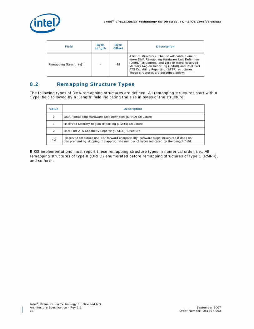
Intel® Virtualization Technology for Directed I/O—BIOS Considerations
Intel® Virtualization Technology for Directed I/OArchitecture Specification - Rev 1.1 September 200768 Order Number: D51397-003
8.2 Remapping Structure Types
The following types of DMA-remapping structures are defined. All remapping structures start with a ‘Type’ field followed by a ‘Length’ field indicating the size in bytes of the structure.
BIOS implementations must report these remapping structure types in numerical order. i.e., All remapping structures of type 0 (DRHD) enumerated before remapping structures of type 1 (RMRR), and so forth.
Remapping Structures[] - 48
A list of structures. The list will contain one or more DMA Remapping Hardware Unit Definition (DRHD) structures, and zero or more Reserved Memory Region Reporting (RMRR) and Root Port ATS Capability Reporting (ATSR) structures. These structures are described below.
Value Description
0 DMA Remapping Hardware Unit Definition (DRHD) Structure
1 Reserved Memory Region Reporting (RMRR) Structure
2 Root Port ATS Capability Reporting (ATSR) Structure
>2 Reserved for future use. For forward compatibility, software skips structures it does not comprehend by skipping the appropriate number of bytes indicated by the Length field.
Field Byte Length
Byte Offset Description
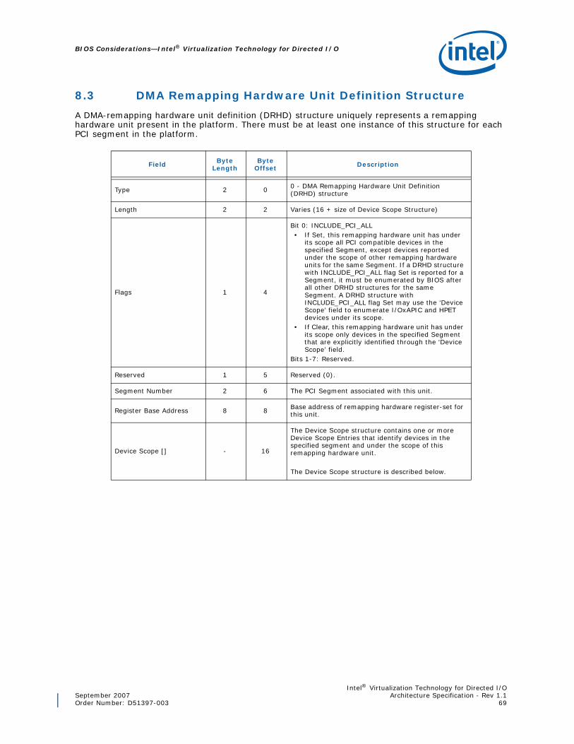
Intel® Virtualization Technology for Directed I/OSeptember 2007 Architecture Specification - Rev 1.1Order Number: D51397-003 69
BIOS Considerations—Intel® Virtualization Technology for Directed I/O
8.3 DMA Remapping Hardware Unit Definition Structure
A DMA-remapping hardware unit definition (DRHD) structure uniquely represents a remapping hardware unit present in the platform. There must be at least one instance of this structure for each PCI segment in the platform.
Field Byte Length
Byte Offset Description
Type 2 0 0 - DMA Remapping Hardware Unit Definition (DRHD) structure
Length 2 2 Varies (16 + size of Device Scope Structure)
Flags 1 4
Bit 0: INCLUDE_PCI_ALL• If Set, this remapping hardware unit has under
its scope all PCI compatible devices in the specified Segment, except devices reported under the scope of other remapping hardware units for the same Segment. If a DRHD structure with INCLUDE_PCI_ALL flag Set is reported for a Segment, it must be enumerated by BIOS after all other DRHD structures for the same Segment. A DRHD structure with INCLUDE_PCI_ALL flag Set may use the ‘Device Scope’ field to enumerate I/OxAPIC and HPET devices under its scope.
• If Clear, this remapping hardware unit has under its scope only devices in the specified Segment that are explicitly identified through the ‘Device Scope’ field.
Bits 1-7: Reserved.
Reserved 1 5 Reserved (0).
Segment Number 2 6 The PCI Segment associated with this unit.
Register Base Address 8 8 Base address of remapping hardware register-set for this unit.
Device Scope [] - 16
The Device Scope structure contains one or more Device Scope Entries that identify devices in the specified segment and under the scope of this remapping hardware unit.
The Device Scope structure is described below.

Intel® Virtualization Technology for Directed I/O—BIOS Considerations
Intel® Virtualization Technology for Directed I/OArchitecture Specification - Rev 1.1 September 200770 Order Number: D51397-003
8.3.1 Device Scope Structure
The Device Scope Structure is made up of one or more Device Scope Entries. Each Device Scope Entry may be used to indicate a PCI endpoint device, a PCI sub-hierarchy, or devices such as I/OxAPICs or HPET (High Precision Event Timer).
In this section, the generic term ‘PCI’ is used to describe conventional PCI, PCI-X, and PCI-Express devices. Similarly, the term ‘PCI-PCI bridge’ is used to refer to conventional PCI bridges, PCI-X bridges, PCI Express root ports, or downstream ports of a PCI Express switch.
A PCI sub-hierarchy is defined as the collection of PCI controllers that are downstream to a specific PCI-PCI bridge. To identify a PCI sub-hierarchy, the Device Scope Entry needs to identify only the parent PCI-PCI bridge of the sub-hierarchy.
Field Byte Length
Byte Offset Description
Type 1 0
The following values are defined for this field.• 0x01: PCI Endpoint Device - The device
identified by the ‘Path’ field is a PCI endpoint device. This type must not be used in Device Scope of DRHD structures with INCLUDE_PCI_ALL flag Set.
• 0x02: PCI Sub-hierarchy - The device identified by the ‘Path’ field is a PCI-PCI bridge. In this case, the specified bridge device and all its downstream devices are included in the scope. This type must not be in Device Scope of DRHD structures with INCLUDE_PCI_ALL flag Set.
• 0x03: IOAPIC - The device identified by the ‘Path’ field is an I/O APIC (or I/O SAPIC) device, enumerated through the ACPI MADT I/O APIC (or I/O SAPIC) structure.
• 0x04: MSI_CAPABLE_HPET1 - The device identified by the ‘Path’ field is an HPET device capable of generating MSI (Message Signaled interrupts). HPET hardware is reported through ACPI HPET structure.
Other values for this field are reserved for future use.
Length 1 1 Length of this Entry in Bytes. (6 + X), where X is the size in bytes of the “Path” field.
Reserved 2 2 Reserved (0).
Enumeration ID 1 4
When the ‘Type’ field indicates ‘IOAPIC’, this field provides the I/O APICID as provided in the I/O APIC (or I/O SAPIC) structure in the ACPI MADT (Multiple APIC Descriptor Table).
This field is treated reserved (0) for all other ‘Type’ fields.
Start Bus Number 1 5
This field describes the bus number (bus number of the first PCI Bus produced by the PCI Host Bridge) under which the device identified by this Device Scope resides.

Intel® Virtualization Technology for Directed I/OSeptember 2007 Architecture Specification - Rev 1.1Order Number: D51397-003 71
BIOS Considerations—Intel® Virtualization Technology for Directed I/O
The following pseudocode describes how to identify the device specified through a Device Scope structure:
n = (DevScope.Length - 6) / 2; // number of entries in the ‘Path’ fieldtype = DevScope.Type; // type of devicebus = DevScope.StartBusNum; // starting bus numberdev = DevScope.Path[0].Device; // starting device numberfunc = DevScope.Path[0].Function; // starting function numberi = 1; while (--n) {
bus = read_secondary_bus_reg(bus, dev, func);// secondary bus# from config reg.dev = DevScope.Path[i].Device; // read next device numberfunc = DevScope.Path[i].Function; // read next function numberi++;
}source_id = {bus, dev, func};target_device = {type, source_id}; // if ‘type’ indicates ‘IOAPIC’, DevScope.EnumID
// provides the I/O APICID as reported in the ACPI MADT
Path 2 * N 6
Describes the hierarchical path from the Host Bridge to the device specified by the Device Scope Entry.
For example, a device in a N-deep hierarchy is identified by N {PCI Device Number, PCI Function Number} pairs, where N is a positive integer. Even offsets contain the Device numbers, and odd offsets contain the Function numbers.
The first {Device, Function} pair resides on the bus identified by the ‘Start Bus Number’ field. Each subsequent pair resides on the bus directly behind the bus of the device identified by the previous pair. The identity (Bus, Device, Function) of the target device is obtained by recursively walking down these N {Device, Function} pairs.
If the ‘Path’ field length is 2 bytes (N=1), the Device Scope Entry identifies a ‘Root-Complex Integrated Device’. The requester-id of ‘Root-Complex Integrated Devices’ are static and not impacted by system software bus rebalancing actions.
If the ‘Path’ field length is more than 2 bytes (N > 1), the Device Scope Entry identifies a device behind one or more system software visible PCI-PCI bridges. Bus rebalancing actions by system software modifying bus assignments of the device’s parent bridge impacts the bus number portion of device’s requester-id.
1. HPET devices not capable of MSI interrupt generation (and instead have their interrupts routed throughI/OxAPIC) are not reported in the Device Scope.
Field Byte Length
Byte Offset Description

Intel® Virtualization Technology for Directed I/O—BIOS Considerations
Intel® Virtualization Technology for Directed I/OArchitecture Specification - Rev 1.1 September 200772 Order Number: D51397-003
8.3.1.1 Reporting Scope for I/OxAPICs
Interrupts from devices that only support (or are only enabled for) legacy interrupts are routed through the I/OxAPICs in the platform. Each I/OxAPIC in the platform is reported to system software through ACPI MADT (Multiple APIC Descriptor Tables). Some platforms may also expose I/OxAPICs as PCI-discoverable devices.
For platforms reporting interrupt remapping capability (INTR_REMAP flag Set in the DMAR structure), each I/OxAPIC in the platform reported through ACPI MADT must be explicitly enumerated under the Device Scope of the appropriate remapping hardware units.
• For I/OxAPICs that are PCI-discoverable, the source-id for such I/OxAPICs (computed using the above pseudocode from its Device Scope structure) must match its PCI requester-id effective at the time of boot.
• For I/OxAPICs that are not PCI-discoverable:
— If the ‘Path’ field in Device Scope has a size of 2 bytes, the corresponding I/OxAPIC is a Root-Complex integrated device. The ‘Start Bus Number’ and ‘Path’ field in the Device Scope structure together provides the unique 16-bit source-id allocated by the platform for the I/OxAPIC. Examples are I/OxAPICs integrated to the IOH and south bridge (ICH) components.
— If the ‘Path’ field in Device Scope has a size greater than 2 bytes, the corresponding I/OxAPIC is behind some software visible PCI-PCI bridge. In this case, the ‘Start Bus Number’ and ‘Path’ field in the Device Scope structure together identifies the PCI-path to the I/OxAPIC device. Bus rebalancing actions by system software modifying bus assignments of the device’s parent bridge impacts the bus number portion of device’s source-id. Examples are I/OxAPICs in PCI-Express-to-PCI-X bridge components in the platform.
8.3.1.2 Reporting Scope for MSI Capable HPET Device
High Precision Event Timer (HPET) device supporting Message Signaled Interrupt (MSI) interrupts may generate interrupt requests directly to the Root-Complex (instead of routing through I/OxAPIC). Platforms supporting interrupt remapping must explicitly enumerate any MSI-capable HPET device in the platform through the Device Scope of the appropriate remapping hardware unit. In this case, the ‘Start Bus Number’ and ‘Path’ field in the Device Scope structure together provides the unique 16-bit source-id allocated by the platform for the MSI-capable HPET device.
8.3.1.3 Device Scope Example
This section provides an example platform configuration with multiple remapping hardware units. The configurations described are hypothetical examples, only intended to illustrate the Device Scope structures.
Figure 8-23 illustrates a platform configuration with a single PCI segment and host bridge (with a starting bus number of 0), and supporting four remapping hardware units as follows:
1. Remapping hardware unit #1 has under its scope all devices downstream to the PCI Express root port located at (dev:func) of (14:0).
2. Remapping hardware unit #2 has under its scope all devices downstream to the PCI Express root port located at (dev:func) of (14:1).
3. Remapping hardware unit #3 has under its scope a Root-Complex integrated endpoint device located at (dev:func) of (29:0).
4. Remapping hardware unit #4 has under its scope all other PCI compatible devices in the platform not explicitly under the scope of the other remapping hardware units. In this example, this includes the integrated device at (dev:func) at (30:0), and all the devices attached to the south bridge component. The I/OxAPIC in the platform (I/O APICID = 0) is under the scope of this remapping hardware unit, and has a BIOS assigned bus/dev/function number of (0,12,0).

Intel® Virtualization Technology for Directed I/OSeptember 2007 Architecture Specification - Rev 1.1Order Number: D51397-003 73
BIOS Considerations—Intel® Virtualization Technology for Directed I/O
This platform requires 4 DRHD structures. The Device Scope fields in each DRHD structure are described as below.
• Device Scope for remapping hardware unit #1 contains only one Device Scope Entry, identified as [2, 8, 0, 0, 0, 14, 0].
— System Software uses the Entry Type field value of 0x02 to conclude that all devices downstream of the PCI-PCI bridge device at PCI Segment 0, Bus 0, Device 14, and Function 0 are within the scope of this remapping hardware unit.
• Device Scope for remapping hardware unit #2 contains only one Device Scope Entry, identified as [2, 8, 0, 0, 0, 14, 1].
— System Software uses the Entry Type field value of 0x02 to conclude that all devices downstream of the PCI-PCI bridge device at PCI Segment 0, Bus 0, Device 14, and Function 1 are within the scope of this remapping hardware unit.
• Device Scope for remapping hardware unit #3 contains only one Device Scope Entry, identified as [1, 8, 0, 0, 0, 29, 0].
— System software uses the Type field value of 0x1 to conclude that the scope of remapping hardware unit #3 includes only the endpoint device at PCI Segment 0, Bus 0, Device 29 and Function 0.
• Device Scope for remapping hardware unit #4 contains only one Device Scope Entry, identified as [3, 8, 0, 1, 0, 12, 0]. Also, the DHRD structure for remapping hardware unit #4 indicates the INCLUDE_PCI_ALL flag. This hardware unit must be the last in the list of hardware unit definition structures reported.
— System software uses the INCLUDE_PCI_ALL flag to conclude that all PCI compatible devices that are not explicitly enumerated under other remapping hardware units are in the scope of remapping unit #4. Also, the Device Scope Entry with Type field value of 0x3 is used to
Figure 8-23. Hypothetical Platform Configuration
Processor
System Bus
South Bridge
DRAM
Processor
PCI Express Devices
DMA Remapping
Unit #1Integrated
DeviceDev [30:0]
PCIe Root Port
Dev [14:0]
PCI, LPC,Legacy devices
DMA Remapping
Unit #2PCIe Root
PortDev [14:1]
DMA Remapping
Unit #3Integrated
DeviceDev [29:0]
DMA Remapping Unit #4
Host Bridge [Bus #0]
I/OxAPIC
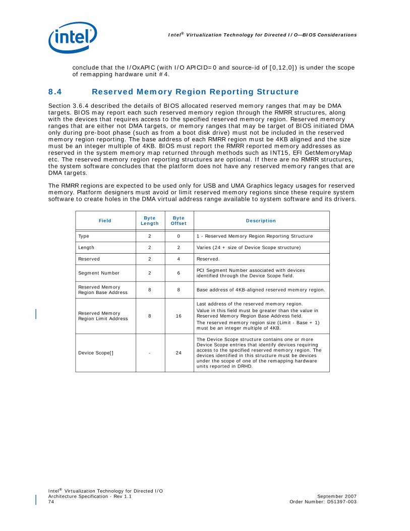
Intel® Virtualization Technology for Directed I/O—BIOS Considerations
Intel® Virtualization Technology for Directed I/OArchitecture Specification - Rev 1.1 September 200774 Order Number: D51397-003
conclude that the I/OxAPIC (with I/O APICID=0 and source-id of [0,12,0]) is under the scope of remapping hardware unit #4.
8.4 Reserved Memory Region Reporting Structure
Section 3.6.4 described the details of BIOS allocated reserved memory ranges that may be DMA targets. BIOS may report each such reserved memory region through the RMRR structures, along with the devices that requires access to the specified reserved memory region. Reserved memory ranges that are either not DMA targets, or memory ranges that may be target of BIOS initiated DMA only during pre-boot phase (such as from a boot disk drive) must not be included in the reserved memory region reporting. The base address of each RMRR region must be 4KB aligned and the size must be an integer multiple of 4KB. BIOS must report the RMRR reported memory addresses as reserved in the system memory map returned through methods such as INT15, EFI GetMemoryMap etc. The reserved memory region reporting structures are optional. If there are no RMRR structures, the system software concludes that the platform does not have any reserved memory ranges that are DMA targets.
The RMRR regions are expected to be used only for USB and UMA Graphics legacy usages for reserved memory. Platform designers must avoid or limit reserved memory regions since these require system software to create holes in the DMA virtual address range available to system software and its drivers.
Field Byte Length
Byte Offset Description
Type 2 0 1 - Reserved Memory Region Reporting Structure
Length 2 2 Varies (24 + size of Device Scope structure)
Reserved 2 4 Reserved.
Segment Number 2 6 PCI Segment Number associated with devices identified through the Device Scope field.
Reserved Memory Region Base Address 8 8 Base address of 4KB-aligned reserved memory region.
Reserved Memory Region Limit Address 8 16
Last address of the reserved memory region.Value in this field must be greater than the value in Reserved Memory Region Base Address field.The reserved memory region size (Limit - Base + 1) must be an integer multiple of 4KB.
Device Scope[] - 24
The Device Scope structure contains one or more Device Scope entries that identify devices requiring access to the specified reserved memory region. The devices identified in this structure must be devices under the scope of one of the remapping hardware units reported in DRHD.

Intel® Virtualization Technology for Directed I/OSeptember 2007 Architecture Specification - Rev 1.1Order Number: D51397-003 75
BIOS Considerations—Intel® Virtualization Technology for Directed I/O
8.5 Root Port ATS Capability Reporting Structure
This structure is applicable only for platforms supporting Device-IOTLBs as reported through the Extended Capability register. For each PCI Segment in the platform that supports Device-IOTLBs, BIOS provides an ATSR structure. The ATSR structures identifies PCI Express Root-Ports supporting Address Translation Services (ATS) transactions. Software must enable ATS on endpoint devices behind a Root Port only if the Root Port is reported as supporting ATS transactions.
Field Byte Length
Byte Offset Description
Type 2 0 2 - Root Port ATS Capability Reporting Structure
Length 2 2 Varies (8 + size of Device Scope Structure)
Flags 1 4
• Bit 0: ALL_PORTS: If Set, indicates all PCI Express Root Ports in the specified PCI Segment supports ATS transactions. If Clear, indicates ATS transactions are supported only on Root Ports identified through the Device Scope field.
• Bits 1-7: Reserved.
Reserved 1 5 Reserved (0).
Segment Number 2 6 The PCI Segment associated with this ATSR structure.
Device Scope [] - 8
If the ALL_PORTS flag is Set, the Device Scope structure is omitted.If ALL_PORTS flag is Clear, the Device Scope structure contains Device Scope Entries that identifies Root Ports supporting ATS transactions. The Device Scope structure is described in Section 8.3.1. All Device Scope Entries in this structure must have a Device Scope Entry Type of 02h.

Intel® Virtualization Technology for Directed I/O—Translation Structure Formats
Intel® Virtualization Technology for Directed I/OArchitecture Specification - Rev 1.1 September 200776 Order Number: D51397-003
9 Translation Structure Formats
This chapter describes the memory-resident structures for DMA and interrupt remapping.
9.1 Root-entry
The following figure and table describe the root-entry.
Figure 9-24. Root-Entry Format
27
Reserved (0)
64
1
0163
12
11
Reserved (0)
CTP
P
HAW HAW -1
Reserved (0)

Intel® Virtualization Technology for Directed I/OSeptember 2007 Architecture Specification - Rev 1.1Order Number: D51397-003 77
Translation Structure Formats—Intel® Virtualization Technology for Directed I/O
Bits Field Description
127:64 R: Reserved Reserved. Must be 0. This field is evaluated by hardware only when the Present (P) field is Set.
63:12 CTP: Context-entry Table Pointer
Pointer to context-entry table for this bus. The context-entry table is 4KB in size and size-aligned.
This field is evaluated by hardware only when the Present (P) field is Set. When evaluated, hardware treats bits 63:HAW as reserved (0), where HAW is the host address width of the platform.
11:1 R: Reserved Reserved. Must be 0. This field is evaluated by hardware only when the Present (P) field is Set.
0 P: Present
This field indicates whether the root-entry is present.• 0: Indicates the root-entry is not present. Hardware blocks
DMA requests processed through root entries with the present field cleared.
• 1: Indicates the root-entry is present. Hardware processes DMA requests per the context-entries referenced by the CTP field.

Intel® Virtualization Technology for Directed I/O—Translation Structure Formats
Intel® Virtualization Technology for Directed I/OArchitecture Specification - Rev 1.1 September 200778 Order Number: D51397-003
9.2 Context-entry
The following figure and table describe the context-entry.
Figure 9-25. Context-Entry Format
27
88
A W
R e se rv e d (0 )
D ID
E H
67
64
187
70
66
R e se rv e d (0 )
17
A V A IL
27
012363
12
11
F P DT
A S R
P
4H A W H A W -1
R e se rv e d (0 )
R e se rv e d (0 )
56
A LH

Intel® Virtualization Technology for Directed I/OSeptember 2007 Architecture Specification - Rev 1.1Order Number: D51397-003 79
Translation Structure Formats—Intel® Virtualization Technology for Directed I/O
Bits Field Description
127:88 R: Reserved Reserved. Must be 0. This field is evaluated by hardware only when the Present (P) field is Set.
87:72 DID: Domain Identifier
Identifier for the domain to which this context-entry maps. Hardware may use the domain identifier to tag its internal caches.
The Capability register reports the domain-id width supported by hardware. For implementations supporting less than 16-bit domain-ids, unused bits of this field are treated as reserved by hardware. For example, for an implementation supporting 8-bit domain-ids, bits 87:80 of this field are treated as reserved.
Context-entries programmed with the same domain identifier must always reference the same address translation structure (through the ASR field). Similarly, context-entries referencing the same address translation structure must be programmed with the same domain id.
This field is evaluated by hardware only when the Present (P) field is Set.
When Caching Mode (CM) field is reported as Set, the domain-id value of zero is architecturally reserved. Software must not use domain-id value of zero when CM is Set.
71 R: Reserved Reserved. Must be 0. This field is evaluated by hardware only when the Present (P) field is Set.
70:67 AVAIL: Available This field is available to software. Hardware always ignores the programming of this field.
66:64 AW: Address Width
When the translation-type (T) field indicates multi-level page tables, this field indicates the adjusted guest-address-width (AGAW) to be used by hardware for the page-table walk. The following encodings are defined for this field: • 000b: 30-bit AGAW (2-level page table)• 001b: 39-bit AGAW (3-level page table)• 010b: 48-bit AGAW (4-level page table)• 011b: 57-bit AGAW (5-level page table)• 100b: 64-bit AGAW (6-level page table)• 101b-111b: Reserved
The value specified in this field must match an AGAW value supported by hardware (as reported in the SAGAW field in the Capability register).
DMA requests processed through this context-entry and accessing DMA virtual addresses above 2X-1 (where X is the AGAW value indicated by this field) are blocked1.
This field is evaluated by hardware only when the Present (P) field is Set.
63:12 ASR: Address Space Root
When the translation-type (T) field indicates multi-level page tables, this field points to the base of the page-table root.
This field is evaluated by hardware only when the Present (P) field is Set. When evaluated, hardware treats bits 63:HAW as reserved, where HAW is the host address width of the platform.
11:6 R: Reserved Reserved. Must be 0. This field is evaluated by hardware only when the Present (P) field is Set.

Intel® Virtualization Technology for Directed I/O—Translation Structure Formats
Intel® Virtualization Technology for Directed I/OArchitecture Specification - Rev 1.1 September 200780 Order Number: D51397-003
5 ALH: Address Locality Hint
This field may be Set by software if DMA requests processed through this context-entry are expected to demonstrate spatial address locality. For usages where DMA address locality can be controlled by software, setting this field is most beneficial and recommended for high-throughput devices with small payload requests (such as NIC devices). Hardware implementations may utilize this hint field to pre-fetch and cache adjacent present mappings for improved performance. Any fault conditions detected on pre-fetched mappings must be ignored by hardware and not reported to software.
This field is treated as reserved by hardware implementations reporting CH (Caching Hints) field as Clear in the Extended Capability register.When supported, this field is evaluated by hardware only when Present (P) field is Set.
4 EH: Eviction Hint
This field may be Set by software to change the IOTLB default eviction policy in hardware.• 0: The default eviction policy of hardware is in effect for IOTLB
entries corresponding to DMA requests processed through this context-entry.
• 1: Hardware may eagerly evict IOTLB entries hosting effective translations with TM field Set. Refer to Page-table Entry format in Section 9.3 for details on TM field. Software may Set the EH field if device commonly uses transient DMA buffers.
This field is treated as reserved by hardware implementations reporting CH (Caching Hints) field as Clear in the Extended Capability register.When supported, this field is evaluated by hardware only when Present (P) field is Set.
3:2 T: Translation Type
• 00b: Indicates ASR field points to a multi-level page-table, and only Untranslated DMA requests are translated through this page-table. Translated DMA requests and Translation Requests are blocked.
• 01b: Indicates ASR field points to a multi-level page-table, and Untranslated, Translated and Translation Requests are supported. This encoding is treated as reserved by hardware implementations not supporting Device- IOTLBs (DI field Clear in Extended Capability register).
• 10b: Indicates DMA requests with Untranslated addresses are processed as pass-through. In this case, the AW and ASR fields are ignored by hardware. Translated and Translation Requests are blocked. This encoding is treated by hardware as reserved for hardware implementations reporting PT (Pass Through) field as Clear in the Extended Capability register.
• 11b: Reserved.This field is evaluated by hardware only when Present (P) field is Set.
1FPD: Fault Processing Disable
Enables or disables recording/reporting of faults caused by DMA requests processed through this context-entry:• 0: Indicates fault recording/reporting is enabled for DMA requests
processed through this context-entry. • 1: Indicates fault recording/reporting is disabled for DMA requests
processed through this context-entry.This field is evaluated by hardware irrespective of the setting of the present (P) field.
0 P: Present• 0: Block DMA processed through this context-entry.• 1: Process DMA through this context-entry based on the
programming of other fields.
1. Untranslated DMA and DMA Translation requests to addresses beyond the Maximum Guest Address Width(MGAW) supported by hardware may be blocked and reported through other means such as PCI ExpressAdvanced Error Reporting (AER). Such errors (referred to as platform errors) may not be reported asDMA-remapping faults and are outside the scope of this specification.
Bits Field Description

Intel® Virtualization Technology for Directed I/OSeptember 2007 Architecture Specification - Rev 1.1Order Number: D51397-003 81
Translation Structure Formats—Intel® Virtualization Technology for Directed I/O
9.3 Page-Table Entry
The following figure and table describe the page-table entry.
Figure 9-26. Page-Table-Entry Format
012663
12
11
RW
SP
ADDR
SNP
78HAW HAW -1
AVAIL
AVAIL
26
16
TMRSVD
10
AVAIL
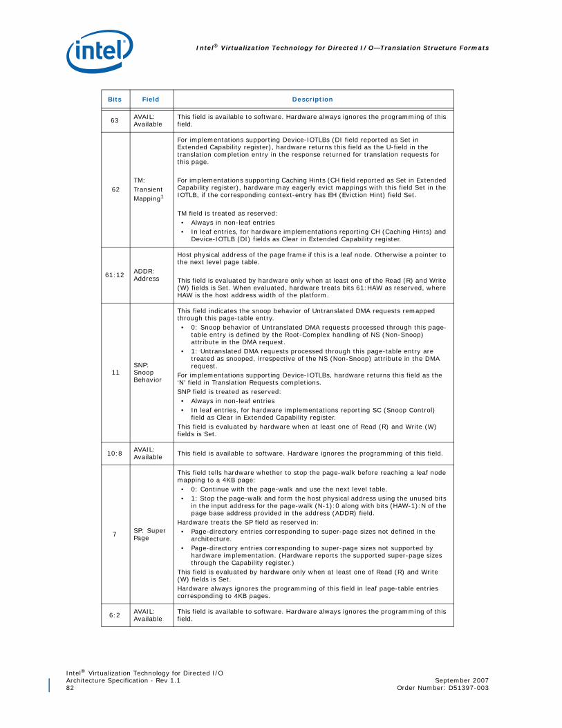
Intel® Virtualization Technology for Directed I/O—Translation Structure Formats
Intel® Virtualization Technology for Directed I/OArchitecture Specification - Rev 1.1 September 200782 Order Number: D51397-003
Bits Field Description
63 AVAIL: Available
This field is available to software. Hardware always ignores the programming of this field.
62TM: Transient Mapping1
For implementations supporting Device-IOTLBs (DI field reported as Set in Extended Capability register), hardware returns this field as the U-field in the translation completion entry in the response returned for translation requests for this page.
For implementations supporting Caching Hints (CH field reported as Set in Extended Capability register), hardware may eagerly evict mappings with this field Set in the IOTLB, if the corresponding context-entry has EH (Eviction Hint) field Set.
TM field is treated as reserved:• Always in non-leaf entries• In leaf entries, for hardware implementations reporting CH (Caching Hints) and
Device-IOTLB (DI) fields as Clear in Extended Capability register.
61:12 ADDR: Address
Host physical address of the page frame if this is a leaf node. Otherwise a pointer to the next level page table.
This field is evaluated by hardware only when at least one of the Read (R) and Write (W) fields is Set. When evaluated, hardware treats bits 61:HAW as reserved, where HAW is the host address width of the platform.
11SNP: Snoop Behavior
This field indicates the snoop behavior of Untranslated DMA requests remapped through this page-table entry. • 0: Snoop behavior of Untranslated DMA requests processed through this page-
table entry is defined by the Root-Complex handling of NS (Non-Snoop) attribute in the DMA request.
• 1: Untranslated DMA requests processed through this page-table entry are treated as snooped, irrespective of the NS (Non-Snoop) attribute in the DMA request.
For implementations supporting Device-IOTLBs, hardware returns this field as the ‘N’ field in Translation Requests completions.SNP field is treated as reserved:• Always in non-leaf entries• In leaf entries, for hardware implementations reporting SC (Snoop Control)
field as Clear in Extended Capability register.This field is evaluated by hardware when at least one of Read (R) and Write (W) fields is Set.
10:8 AVAIL: Available This field is available to software. Hardware ignores the programming of this field.
7 SP: Super Page
This field tells hardware whether to stop the page-walk before reaching a leaf node mapping to a 4KB page:• 0: Continue with the page-walk and use the next level table.• 1: Stop the page-walk and form the host physical address using the unused bits
in the input address for the page-walk (N-1):0 along with bits (HAW-1):N of the page base address provided in the address (ADDR) field.
Hardware treats the SP field as reserved in:• Page-directory entries corresponding to super-page sizes not defined in the
architecture.• Page-directory entries corresponding to super-page sizes not supported by
hardware implementation. (Hardware reports the supported super-page sizes through the Capability register.)
This field is evaluated by hardware only when at least one of Read (R) and Write (W) fields is Set.Hardware always ignores the programming of this field in leaf page-table entries corresponding to 4KB pages.
6:2 AVAIL: Available
This field is available to software. Hardware always ignores the programming of this field.

Intel® Virtualization Technology for Directed I/OSeptember 2007 Architecture Specification - Rev 1.1Order Number: D51397-003 83
Translation Structure Formats—Intel® Virtualization Technology for Directed I/O
1 W: Write
Indicates whether the page is writable for DMA: • 0: Indicates the page is not accessible to DMA write requests.DMA write
requests processed through this page-table entry are blocked. • 1: Indicates the page is accessible to DMA write requests.
0 R: Read
Indicates whether the page is readable for DMA:• 0: Indicates the page is not accessible to DMA read requests. DMA read
requests processed through this page-table entry are blocked. For implementations reporting ZLR field as Set in the Capability register, Read permission is not applicable to zero-length DMA read requests to write-only pages.
• 1: Indicates the page is accessible to DMA read requests.
1. Setting the TM field in a page-table entry does not change software requirements for invalidating the IOTLBwhen modifying the page-table entry.
Bits Field Description

Intel® Virtualization Technology for Directed I/O—Translation Structure Formats
Intel® Virtualization Technology for Directed I/OArchitecture Specification - Rev 1.1 September 200784 Order Number: D51397-003
9.4 Fault Record
The following figure and table describe the fault record format for advanced fault logging.
Figure 9-27. Fault-Record Format
27
F I
64
1
063
FR
S ID
T
R ese rved (0 )
79
80
11
12
95
96
03
04
125
126
1
R ese rved (0 )
R e se rved (0 )
R e se rved (0 )
124
123
1
A T

Intel® Virtualization Technology for Directed I/OSeptember 2007 Architecture Specification - Rev 1.1Order Number: D51397-003 85
Translation Structure Formats—Intel® Virtualization Technology for Directed I/O
Bits Field Description
127 R: Reserved Reserved (0).
126 T: Type
Memory access type of faulted DMA request. This field is valid only when the Fault Reason (FR) indicates one of the DMA-remapping fault conditions.• 0: DMA Write• 1: DMA Read request
125:124 AT: Address TypeAT field in the faulted DMA request. This field is valid only when the Fault Reason (FR) indicates one of the DMA-remapping fault conditions.
123:104 R: Reserved Reserved (0).
103:96 FR: Fault Reason Reason for DMA-remapping fault.
95:80 R: Reserved Reserved (0).
79:64 SID: Source Identifier Requester-id associated with the fault condition.
63:12 FI: Fault Information
When the Fault Reason (FR) field indicates one of the DMA-remapping fault conditions, bits 63:12 of this field contains the page address in the faulted DMA request.When the Fault Reason (FR) field indicates one of the interrupt-remapping fault conditions, bits 63:48 of this field contains the interrupt_index computed for the faulted interrupt request, and bits 48:12 are cleared.
11:0 R: Reserved Reserved (0).

Intel® Virtualization Technology for Directed I/O—Translation Structure Formats
Intel® Virtualization Technology for Directed I/OArchitecture Specification - Rev 1.1 September 200786 Order Number: D51397-003
9.5 Interrupt Remapping Table Entry (IRTE)
The following figure and table describe the interrupt remapping table entry.
Figure 9-28. Interrupt Remapping Table Entry Format
27
Redirection Hint
64
1
01 23
FPD
Destination Mode
AVAIL
P
Vector
431
32
Delivery Mode
63
Trigger Mode
57811
Reserved (0)
SID
SVTReserved (0)
SQ
16
15
23
Destination ID
79
80
81
82
83
84
24
12
Reserved (0)
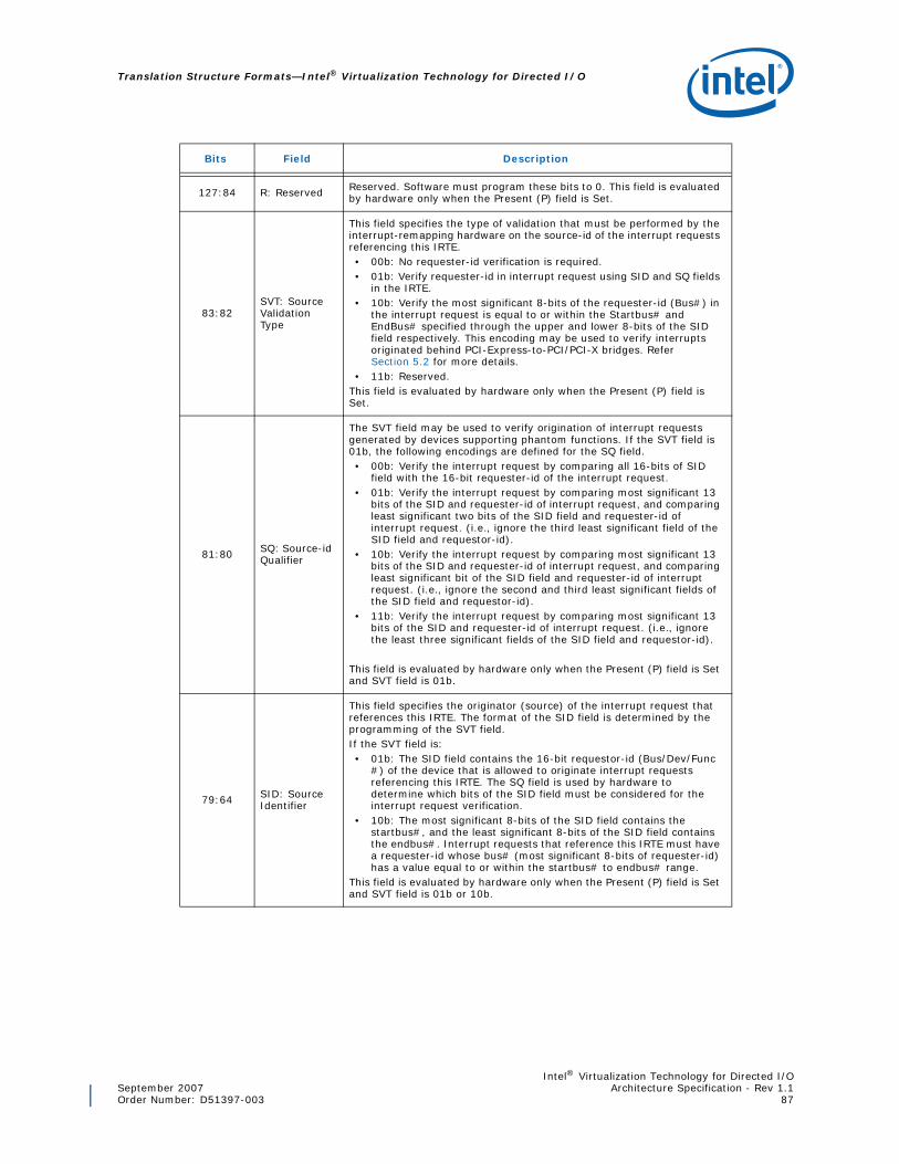
Intel® Virtualization Technology for Directed I/OSeptember 2007 Architecture Specification - Rev 1.1Order Number: D51397-003 87
Translation Structure Formats—Intel® Virtualization Technology for Directed I/O
Bits Field Description
127:84 R: Reserved Reserved. Software must program these bits to 0. This field is evaluated by hardware only when the Present (P) field is Set.
83:82SVT: Source Validation Type
This field specifies the type of validation that must be performed by the interrupt-remapping hardware on the source-id of the interrupt requests referencing this IRTE.• 00b: No requester-id verification is required.• 01b: Verify requester-id in interrupt request using SID and SQ fields
in the IRTE.• 10b: Verify the most significant 8-bits of the requester-id (Bus#) in
the interrupt request is equal to or within the Startbus# and EndBus# specified through the upper and lower 8-bits of the SID field respectively. This encoding may be used to verify interrupts originated behind PCI-Express-to-PCI/PCI-X bridges. Refer Section 5.2 for more details.
• 11b: Reserved.This field is evaluated by hardware only when the Present (P) field is Set.
81:80 SQ: Source-id Qualifier
The SVT field may be used to verify origination of interrupt requests generated by devices supporting phantom functions. If the SVT field is 01b, the following encodings are defined for the SQ field.• 00b: Verify the interrupt request by comparing all 16-bits of SID
field with the 16-bit requester-id of the interrupt request.• 01b: Verify the interrupt request by comparing most significant 13
bits of the SID and requester-id of interrupt request, and comparing least significant two bits of the SID field and requester-id of interrupt request. (i.e., ignore the third least significant field of the SID field and requestor-id).
• 10b: Verify the interrupt request by comparing most significant 13 bits of the SID and requester-id of interrupt request, and comparing least significant bit of the SID field and requester-id of interrupt request. (i.e., ignore the second and third least significant fields of the SID field and requestor-id).
• 11b: Verify the interrupt request by comparing most significant 13 bits of the SID and requester-id of interrupt request. (i.e., ignore the least three significant fields of the SID field and requestor-id).
This field is evaluated by hardware only when the Present (P) field is Set and SVT field is 01b.
79:64 SID: Source Identifier
This field specifies the originator (source) of the interrupt request that references this IRTE. The format of the SID field is determined by the programming of the SVT field.If the SVT field is:• 01b: The SID field contains the 16-bit requestor-id (Bus/Dev/Func
#) of the device that is allowed to originate interrupt requests referencing this IRTE. The SQ field is used by hardware to determine which bits of the SID field must be considered for the interrupt request verification.
• 10b: The most significant 8-bits of the SID field contains the startbus#, and the least significant 8-bits of the SID field contains the endbus#. Interrupt requests that reference this IRTE must have a requester-id whose bus# (most significant 8-bits of requester-id) has a value equal to or within the startbus# to endbus# range.
This field is evaluated by hardware only when the Present (P) field is Set and SVT field is 01b or 10b.
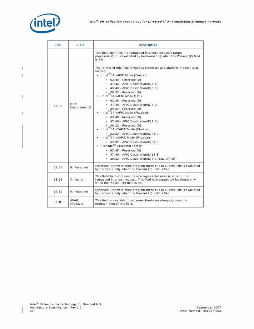
Intel® Virtualization Technology for Directed I/O—Translation Structure Formats
Intel® Virtualization Technology for Directed I/OArchitecture Specification - Rev 1.1 September 200788 Order Number: D51397-003
63:32 DST: Destination ID
This field identifies the remapped interrupt request’s target processor(s). It is evaluated by hardware only when the Present (P) field is Set.
The format of this field in various processor and platform modes1 is as follows:• Intel®64 xAPIC Mode (Cluster):
• 63:48 - Reserved (0)• 47:44 - APIC DestinationID[7:4]• 43:40 - APIC DestinationID[3:0]• 39:32 - Reserved (0)
• Intel®64 xAPIC Mode (Flat):
• 63:48 - Reserved (0)• 47:40 - APIC DestinationID[7:0]• 39:32 - Reserved (0)
• Intel®64 xAPIC Mode (Physical):
• 63:48 - Reserved (0)• 47:40 - APIC DestinationID[7:0]• 39:32 - Reserved (0)
• Intel®64 x2APIC Mode (Cluster):
• 63:32 - APIC DestinationID[31:0]• Intel®64 x2APIC Mode (Physical):
• 63:32 - APIC DestinationID[31:0]• ItaniumTM Processor Family:
• 63:48 - Reserved (0)• 47:40 - APIC DestinationID[15:8]• 39:32 - APIC DestinationID[7:0] (EDID[7:0])
31:24 R: Reserved Reserved. Software must program these bits to 0. This field is evaluated by hardware only when the Present (P) field is Set.
23:16 V: VectorThis 8-bit field contains the interrupt vector associated with the remapped interrupt request. This field is evaluated by hardware only when the Present (P) field is Set.
15:12 R: Reserved Reserved. Software must program these bits to 0. This field is evaluated by hardware only when the Present (P) field is Set.
11:8 AVAIL: Available
This field is available to software. Hardware always ignores the programming of this field.
Bits Field Description

Intel® Virtualization Technology for Directed I/OSeptember 2007 Architecture Specification - Rev 1.1Order Number: D51397-003 89
Translation Structure Formats—Intel® Virtualization Technology for Directed I/O
7:5 DLM: Delivery Mode
This 3-bit field specifies how the remapped interrupt is handled. Delivery Modes operate only in conjunction with specified Trigger Modes (TM). Correct Trigger Modes must be guaranteed by software. Restrictions are indicated below:• 000b (Fixed Mode) – Deliver the interrupt to all the agents indicated
by the Destination ID field. The Trigger Mode for fixed delivery mode can be edge or level.
• 001b (Lowest Priority) – Deliver the interrupt to one (and only one) of the agents indicated by the Destination ID field (the algorithm to pick the target agent is component specific and could include priority based algorithm). The Trigger Mode can be edge or level.
• 010b (System Management Interrupt or SMI): SMI is an edge triggered interrupt regardless of the setting of the Trigger Mode (TM) field. For systems that rely on SMI semantics, the vector field is ignored, but must be programmed to all zeroes for future compatibility. (Support for this delivery mode is implementation specific. Platforms supporting interrupt remapping are expected to generate SMI through dedicated pin or platform-specific special messages)2
• 100b (NMI) – Deliver the signal to all the agents listed in the destination field. The vector information is ignored. NMI is an edge triggered interrupt regardless of the Trigger Mode (TM) setting. (Platforms supporting interrupt remapping are recommended to generate NMI through dedicated pin or platform-specific special messages)2
• 101b (INIT) – Deliver this signal to all the agents indicated by the Destination ID field. The vector information is ignored. INIT is an edge triggered interrupt regardless of the Trigger Mode (TM) setting. (Support for this delivery mode is implementation specific. Platforms supporting interrupt remapping are expected to generate INIT through dedicated pin or platform-specific special messages)2
• 111b (ExtINT) – Deliver the signal to the INTR signal of all agents indicated by the Destination ID field (as an interrupt that originated from an 8259A compatible interrupt controller). The vector is supplied by the INTA cycle issued by the activation of the ExtINT. ExtINT is an edge triggered interrupt regardless of the Trigger Mode (TM) setting.
This field is evaluated by hardware only when the Present (P) field is Set.
4 TM: Trigger Mode
This field indicates the signal type of the interrupt that uses the IRTE.• 0: Indicates edge sensitive.• 1: Indicates level sensitive.
This field is evaluated by hardware only when the Present (P) field is Set.
3RH: Redirection Hint
This bit indicates whether the remapped interrupt request should be directed to one among N processors specified in Destination ID field, under hardware control.• 0: When RH is 0, the remapped interrupt is directed to the
processor listed in the Destination ID field.• 1: When RH is 1, the remapped interrupt is directed to 1 of N
processors specified in the Destination ID field.This field is evaluated by hardware only when the present (P) field is Set.
2DM: Destination Mode
This field indicates whether the Destination ID field in an IRTE should be interpreted as logical or physical APIC ID. • 0: Physical• 1: Logical
This field is evaluated by hardware only when the present (P) field is Set.
Bits Field Description

Intel® Virtualization Technology for Directed I/O—Translation Structure Formats
Intel® Virtualization Technology for Directed I/OArchitecture Specification - Rev 1.1 September 200790 Order Number: D51397-003
1FPD: Fault Processing Disable
Enables or disables recording/reporting of faults caused by interrupt messages requests processed through this entry.• 0: Indicates fault recording/reporting is enabled for interrupt
requests processed through this entry. • 1: Indicates fault recording/reporting is disabled for interrupt
requests processed through this entry.This field is evaluated by hardware irrespective of the setting of the Present (P) field.
0 P: Present
The P field is used by software to indicate to hardware if the corresponding IRTE is present and initialized. • 0: Indicates the IRTE is not currently allocated to any interrupt
sources. Block interrupt requests referencing this IRTE. • 1: Process interrupt requests referencing this IRTE per the
programming of other fields in this IRTE.
1. The various processor and platform interrupt modes (like Intel®64 xAPIC mode, Intel®64 x2APIC modeand ItaniumTM processor mode) are determined by platform/processor specific mechanisms and areoutside the scope of this specification.
2. Refer Section 5.7 for hardware considerations for handling platform events.
Bits Field Description

Intel® Virtualization Technology for Directed I/OSeptember 2007 Architecture Specification - Rev 1.1Order Number: D51397-003 91
Register Descriptions—Intel® Virtualization Technology for Directed I/O
10 Register Descriptions
This chapter describes the structure and use of the remapping registers.
10.1 Register Location
The register set for each remapping hardware unit in the platform is placed at a 4KB-aligned memory-mapped location. The exact location of the register region is implementation-dependent, and is communicated to system software by BIOS through the ACPI DMA-remapping hardware reporting structures (described in Chapter 8). For security, hardware implementations that support relocating these registers in the system address map must provide ability to lock its location by hardware specific secure initialization software.
10.2 Software Access to Registers
Software interacts with the remapping hardware by reading and writing its memory-mapped registers. The following requirements are defined for software access to these registers.
• Software is expected to access 32-bit registers as aligned doublewords. For example, to modify a field (e.g., bit or byte) in a 32-bit register, the entire doubleword is read, the appropriate field(s) are modified, and the entire doubleword is written back.
• Software must access 64-bit and 128-bit registers as either aligned quadwords or aligned doublewords. Hardware may disassemble a quadword register access as two double-word accesses. In such cases, hardware is required to complete the quad-word read or write request in a single clock in order (lower doubleword first, upper double-word second).
• When updating registers through multiple accesses (whether in software or due to hardware disassembly), certain registers may have specific requirements on how the accesses must be ordered for proper behavior. These are documented as part of the respective register descriptions.
• For compatibility with future extensions or enhancements, software must assign the last read value to all “Reserved and Preserved” (RsvdP) fields when written. In other words, any updates to a register must be read so that the appropriate merge between the RsvdP and updated fields will occur. Also, software must assign a value of zero for “Reserved and Zero” (RsvdZ) fields when written.
• Locked operations to remapping hardware registers are not supported. Software must not issue locked operations to access remapping hardware registers.
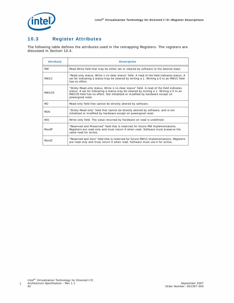
Intel® Virtualization Technology for Directed I/O—Register Descriptions
Intel® Virtualization Technology for Directed I/OArchitecture Specification - Rev 1.1 September 200792 Order Number: D51397-003
10.3 Register Attributes
The following table defines the attributes used in the remapping Registers. The registers are discussed in Section 10.4.
Attribute Description
RW Read-Write field that may be either set or cleared by software to the desired state.
RW1C“Read-only status, Write-1-to-clear status” field. A read of the field indicates status. A set bit indicating a status may be cleared by writing a 1. Writing a 0 to an RW1C field has no effect.
RW1CS
“Sticky Read-only status, Write-1-to-clear status” field. A read of the field indicates status. A set bit indicating a status may be cleared by writing a 1. Writing a 0 to an RW1CS field has no effect. Not initialized or modified by hardware except on powergood reset.
RO Read-only field that cannot be directly altered by software.
ROS “Sticky Read-only” field that cannot be directly altered by software, and is not initialized or modified by hardware except on powergood reset.
WO Write-only field. The value returned by hardware on read is undefined.
RsvdP“Reserved and Preserved” field that is reserved for future RW implementations. Registers are read-only and must return 0 when read. Software must preserve the value read for writes.
RsvdZ “Reserved and Zero” field that is reserved for future RW1C implementations. Registers are read-only and must return 0 when read. Software must use 0 for writes.

Intel® Virtualization Technology for Directed I/OSeptember 2007 Architecture Specification - Rev 1.1Order Number: D51397-003 93
Register Descriptions—Intel® Virtualization Technology for Directed I/O
10.4 Register Descriptions
The following table summarizes the remapping hardware memory-mapped registers.
Offset Register Name Size Description
000h Version Register 32 Architecture version supported by the implementation.
004h Reserved 32 Reserved
008h Capability Register 64 Hardware reporting of capabilities.
010h Extended Capability Register 64 Hardware reporting of extended capabilities.
018h Global Command Register 32 Register controlling general functions.
01Ch Global Status Register 32 Register reporting general status.
020h Root-Entry Table Address Register 64 Register to set up location of root-entry table.
028h Context Command Register 64 Register to manage context-entry cache.
030h Reserved 32 Reserved
034h Fault Status Register 32 Register to report Fault/Error status
038h Fault Event Control Register 32 Interrupt control register for fault events.
03Ch Fault Event Data Register 32 Interrupt message data register for fault events.
040h Fault Event Address Register 32 Interrupt message address register for fault event messages.
044hFault Event Upper Address Register
32 Interrupt message upper address register for fault event messages.
048h Reserved 64 Reserved
050h Reserved 64 Reserved
058hAdvanced Fault Log Register
64 Register to configure and manage advanced fault logging.
060h Reserved 32 Reserved
064h Protected Memory Enable Register 32 Register to enable DMA-protected memory region(s).
068h Protected Low Memory Base Register 32 Register pointing to base of DMA-protected low
memory region.
06Ch Protected Low Memory Limit Register 32 Register pointing to last address (limit) of the
DMA-protected low memory region.
070h Protected High Memory Base Register 64 Register pointing to base of DMA-protected high
memory region.
078h Protected High Memory Limit Register 64 Register pointing to last address (limit) of the
DMA-protected high memory region.
080h Invalidation Queue Head 64 Offset to the invalidation queue entry that will be read next by hardware.
088h Invalidation Queue Tail 64 Offset to the invalidation queue entry that will be written next by software.

Intel® Virtualization Technology for Directed I/O—Register Descriptions
Intel® Virtualization Technology for Directed I/OArchitecture Specification - Rev 1.1 September 200794 Order Number: D51397-003
090h Invalidation Queue Address Register 64 Base address of memory-resident invalidation
queue.
098h Reserved 32 Reserved
09Ch Invalidation Completion Status Register 32 Register to indicate the completion of an
Invalidation Wait Descriptor with IF=1.
0A0h Invalidation Completion Event Control Register 32 Register to control Invalidation Queue Events
0A4h Invalidation Completion Event Data Register 32 Invalidation Queue Event message data register
for Invalidation Queue Events
0A8h Invalidation Completion Event Address Register 32 Invalidation Queue Event message address
register for Invalidation Queue events
0ACh Invalidation Completion Event Upper Address Register 32 Invalidation Queue Event message upper
address register for Invalidation Queue events
0B0h Reserved 64 Reserved
0B8h Interrupt Remapping Table Address Register 64 Register indicating Base Address of Interrupt
Remapping Table.
XXXh IOTLB Registers1 64IOTLB registers consists of two 64-bit registers. Section 10.4.8 describes the format of the registers.
YYYh Fault Recording Registers [n]1 128Registers to record the translation faults. The starting offset of the fault recording registers is reported through the Capability register.
1. Hardware implementations may place IOTLB registers and fault recording registers in any reservedaddresses in the 4KB register space, or place them in adjoined 4KB regions. If one or more adjunct 4KBregions are used, unused addresses in those pages must be treated as reserved by hardware. Location ofthese registers is implementation dependent, and software must read the Capability register to determinetheir offset location.
Offset Register Name Size Description

Intel® Virtualization Technology for Directed I/OSeptember 2007 Architecture Specification - Rev 1.1Order Number: D51397-003 95
Register Descriptions—Intel® Virtualization Technology for Directed I/O
10.4.1 Version Register
Figure 10-29. Version Register
Abbreviation VER_REG
GeneralDescription
Register to report the architecture version supported. Backward compatibility for the architecture is maintained with new revision numbers, allowing software to load remapping hardware drivers written for prior architecture versions.
Register Offset 000h
Bits Access Default Field Description
31:8 RsvdZ 0h R: Reserved Reserved.
7:4 RO 1h MAX: Major Version number Indicates supported architecture version.
3:0 RO 0h MIN: Minor Version number
Indicates supported architecture minor version.
M inM a xR svd
1 8 7 4 3 0 3

Intel® Virtualization Technology for Directed I/O—Register Descriptions
Intel® Virtualization Technology for Directed I/OArchitecture Specification - Rev 1.1 September 200796 Order Number: D51397-003
10.4.2 Capability Register
Figure 10-30. Capability Register
Abbreviation CAP_REG
GeneralDescription Register to report general remapping hardware capabilities
Register Offset 008h
Bits Access Default Field Description
63:56 RsvdZ 0h R: Reserved Reserved.
55 RO X DRD: DMA Read Draining
• 0: Hardware does not support draining of DMA read requests.
• 1: Hardware supports draining of DMA read requests.
Refer Section 6.3 for description of DMA read draining.
54 RO X DWD: DMA Write Draining
• 0: Hardware does not support draining of DMA write requests.
• 1: Hardware supports draining of DMA write requests.
Refer Section 6.3 for description of DMA write draining.
53:48 RO X MAMV: Maximum Address Mask Value
The value in this field indicates the maximum supported value for the Address Mask (AM) field in the Invalidation Address register (IVA_REG) and IOTLB Invalidation Descriptor (iotlb_inv_dsc).
This field is valid only when the PSI field in Capability register is reported as Set.
47:40 RO XNFR: Number of Fault- recording Registers
Number of fault recording registers is computed as N+1, where N is the value reported in this field.
Implementations must support at least one fault recording register (NFR = 0) for each remapping hardware unit in the platform.
The maximum number of fault recording registers per remapping hardware unit is 256.
3 6 5 4 3 8 7 0 9 8 7 4 3 4 3 2 1 6 5 3 2 8 7 6 5 4 3 2 06 5 5 5 5 4 4 4 3 3 3 3 3 2 2 2 2 1 1 1 1
NDAFL
RWBF
PMLR
PMHR
CMSAGAWRsvdMGAW
ZLR
ISOCH
FROSPSRsvd
PSI
NFRMAMVDWD
DRD
Rsvd

Intel® Virtualization Technology for Directed I/OSeptember 2007 Architecture Specification - Rev 1.1Order Number: D51397-003 97
Register Descriptions—Intel® Virtualization Technology for Directed I/O
39 RO X PSI: Page Selective Invalidation
• 0: Hardware supports only global and domain-selective invalidates for IOTLB.
• 1: Hardware supports page-selective, domain-selective, and global invalidates for IOTLB.
Hardware implementations reporting this field as Set are recommended to support a Maximum Address Mask Value (MAMV) value of at least 9.
38 RsvdZ 0h R: Reserved Reserved.
37:34 RO X SPS: Super-Page support
This field indicates the super page sizes supported by hardware.
A value of 1 in any of these bits indicates the corresponding super-page size is supported. The super-page sizes corresponding to various bit positions within this field are: • 0: 21-bit offset to page frame (2MB)• 1: 30-bit offset to page frame (1GB)• 2: 39-bit offset to page frame (512GB)• 3: 48-bit offset to page frame (1TB)
Hardware implementations supporting a specific super-page size must support all smaller super-page sizes. i.e., only valid values for this field are 0001b, 0011b, 0111b, 1111b.
33:24 RO X FRO: Fault-recording Register offset
This field specifies the offset of the first fault recording register relative to the register base address of this remapping hardware unit.
If the register base address is X, and the value reported in this field is Y, the address for the first fault recording register is calculated as X+(16*Y).
23 RO X ISOCH: Isochrony
• 0: Indicates the remapping hardware unit has no critical isochronous requesters in its scope.
• 1: Indicates the remapping hardware unit has one or more critical isochronous requesters in its scope. To guarantee isochronous performance, software must ensure invalidation operations do not impact active DMA streams from such requesters. For example, when isochronous DMA is active, software performs page-selective invalidations (and not coarser invalidations).
22 RO X ZLR: Zero Length Read
• 0: Indicates the remapping hardware unit blocks (and treats as fault) zero length DMA read requests to write-only pages.
• 1: Indicates the remapping hardware unit supports zero length DMA read requests to write-only pages.
DMA remapping hardware implementations are recommended to report ZLR field as Set.
Bits Access Default Field Description

Intel® Virtualization Technology for Directed I/O—Register Descriptions
Intel® Virtualization Technology for Directed I/OArchitecture Specification - Rev 1.1 September 200798 Order Number: D51397-003
21:16 RO X MGAW: Maximum Guest Address Width
This field indicates the maximum DMA virtual addressability supported by remapping hardware. The Maximum Guest Address Width (MGAW) is computed as (N+1), where N is the valued reported in this field. For example, a hardware implementation supporting 48-bit MGAW reports a value of 47 (101111b) in this field.
If the value in this field is X, untranslated and translated DMA requests to addresses above 2(X+1)-1 are always blocked by hardware. Device-IOTLB translation requests to address above 2(X+1)-1 from allowed devices return a null Translation Completion Data Entry with R=W=0.
Guest addressability for a given DMA request is limited to the minimum of the value reported through this field and the adjusted guest address width of the corresponding page-table structure. (Adjusted guest address widths supported by hardware are reported through the SAGAW field).
Implementations are recommended to support MGAW at least equal to the physical addressability (host address width) of the platform.
15:13 RsvdZ 0h R: Reserved Reserved.
12:8 RO XSAGAW: Supported Adjusted Guest Address Widths
This 5-bit field indicates the supported adjusted guest address widths (which in turn represents the levels of page-table walks for the 4KB base page size) supported by the hardware implementation.
A value of 1 in any of these bits indicates the corresponding adjusted guest address width is supported. The adjusted guest address widths corresponding to various bit positions within this field are:• 0: 30-bit AGAW (2-level page-table)• 1: 39-bit AGAW (3-level page-table)• 2: 48-bit AGAW (4-level page-table)• 3: 57-bit AGAW (5-level page-table)• 4: 64-bit AGAW (6-level page-table)
Software must ensure that the adjusted guest address width used to set up the page tables is one of the supported guest address widths reported in this field.
Bits Access Default Field Description

Intel® Virtualization Technology for Directed I/OSeptember 2007 Architecture Specification - Rev 1.1Order Number: D51397-003 99
Register Descriptions—Intel® Virtualization Technology for Directed I/O
7 RO X CM: Caching Mode
• 0: Not-present and erroneous entries are not cached in any of the remapping caches. Invalidations are not required for modifications to individual not present or invalid entries. However, any modifications that result in decreasing the effective permissions or partial permission increases require invalidations for them to be effective.
• 1: Not-present and erroneous mappings may be cached in the remapping caches. Any software updates to the remapping structures (including updates to “not-present” or erroneous entries) require explicit invalidation.
Hardware implementations of this architecture must support a value of 0 in this field. Refer to Section 6.1 for more details on Caching Mode.
6 RO X PHMR: Protected High-Memory Region
• 0: Indicates protected high-memory region is not supported.
• 1: Indicates protected high-memory region is supported.
5 RO XPLMR: Protected Low-Memory Region
• 0: Indicates protected low-memory region is not supported.
• 1: Indicates protected low-memory region is supported.
4 RO X RWBF: Required Write-Buffer Flushing
• 0: Indicates no write-buffer flushing is needed to ensure changes to memory-resident structures are visible to hardware.
• 1: Indicates software must explicitly flush the write buffers to ensure updates made to memory-resident remapping structures are visible to hardware. Refer to Section 11.1 for more details on write buffer flushing requirements.
3 RO X AFL: Advanced Fault Logging
• 0: Indicates advanced fault logging is not supported. Only primary fault logging is supported.
• 1: Indicates advanced fault logging is supported.
2:0 RO X ND: Number of domains supported1
• 000b: Hardware supports 4-bit domain-ids with support for up to 16 domains.
• 001b: Hardware supports 6-bit domain-ids with support for up to 64 domains.
• 010b: Hardware supports 8-bit domain-ids with support for up to 256 domains.
• 011b: Hardware supports 10-bit domain-ids with support for up to 1024 domains.
• 100b: Hardware supports 12-bit domain-ids with support for up to 4K domains.
• 101b: Hardware supports 14-bit domain-ids with support for up to 16K domains.
• 110b: Hardware supports 16-bit domain-ids with support for up to 64K domains.
• 111b: Reserved.
1. Each remapping unit in the platform should support as many number of domains as the maximum numberof independently DMA-remappable devices expected to be attached behind it.
Bits Access Default Field Description
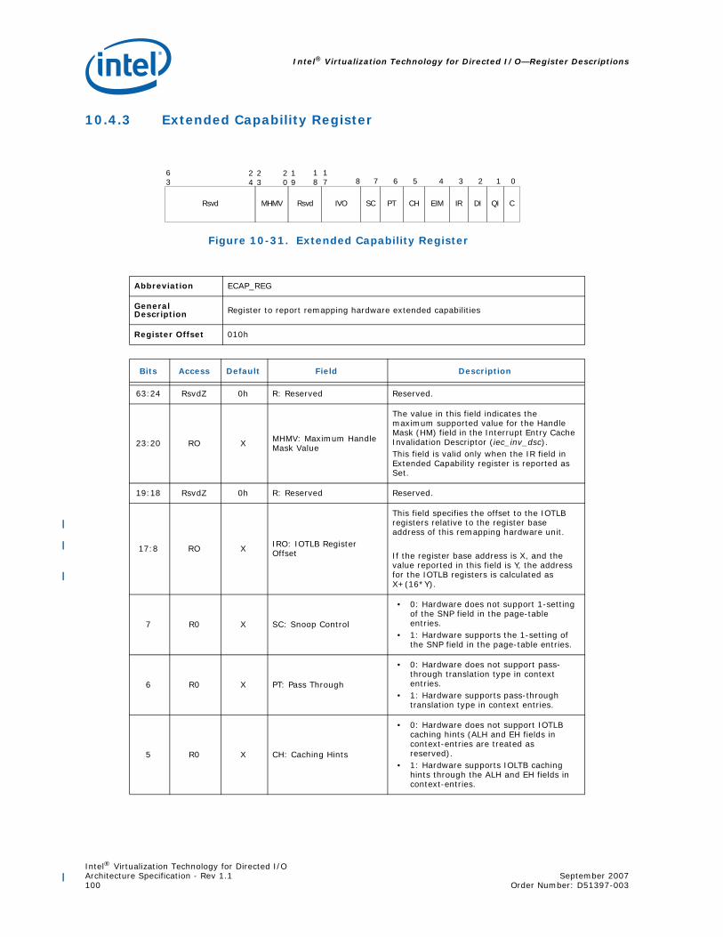
Intel® Virtualization Technology for Directed I/O—Register Descriptions
Intel® Virtualization Technology for Directed I/OArchitecture Specification - Rev 1.1 September 2007100 Order Number: D51397-003
10.4.3 Extended Capability Register
Figure 10-31. Extended Capability Register
Abbreviation ECAP_REG
GeneralDescription Register to report remapping hardware extended capabilities
Register Offset 010h
Bits Access Default Field Description
63:24 RsvdZ 0h R: Reserved Reserved.
23:20 RO X MHMV: Maximum Handle Mask Value
The value in this field indicates the maximum supported value for the Handle Mask (HM) field in the Interrupt Entry Cache Invalidation Descriptor (iec_inv_dsc).This field is valid only when the IR field in Extended Capability register is reported as Set.
19:18 RsvdZ 0h R: Reserved Reserved.
17:8 RO X IRO: IOTLB Register Offset
This field specifies the offset to the IOTLB registers relative to the register base address of this remapping hardware unit.
If the register base address is X, and the value reported in this field is Y, the address for the IOTLB registers is calculated as X+(16*Y).
7 R0 X SC: Snoop Control
• 0: Hardware does not support 1-setting of the SNP field in the page-table entries.
• 1: Hardware supports the 1-setting of the SNP field in the page-table entries.
6 R0 X PT: Pass Through
• 0: Hardware does not support pass-through translation type in context entries.
• 1: Hardware supports pass-through translation type in context entries.
5 R0 X CH: Caching Hints
• 0: Hardware does not support IOTLB caching hints (ALH and EH fields in context-entries are treated as reserved).
• 1: Hardware supports IOLTB caching hints through the ALH and EH fields in context-entries.
01234567817
18
63
19
20
23
24
CQIEIMCHIVORsvd DIIRPTSCRsvdMHMV

Intel® Virtualization Technology for Directed I/OSeptember 2007 Architecture Specification - Rev 1.1Order Number: D51397-003 101
Register Descriptions—Intel® Virtualization Technology for Directed I/O
4 RO 0 EIM: Extended Interrupt Mode
• 0: On Intel®64 platforms, hardware supports only 8-bit APIC-IDs (xAPIC Mode).
• 1: On Intel®64 platforms, hardware supports 32-bit APIC-IDs (x2APIC mode).
This field is valid only on Intel®64 platforms reporting Interrupt Remapping support (IR field Set).ItaniumTM platforms support 16-bit APIC-IDs and always report this field as Clear.
3 RO X IR: Interrupt Remapping support
• 0: Hardware does not support interrupt remapping.
• 1: Hardware supports interrupt remapping.
Implementations reporting this field as Set must also support Queued Invalidation (QI)
2 RO X DI: Device IOTLB support
• 0: Hardware does not support deviceIOTLBs.
• 1: Hardware supports Device-IOTLBs.Implementations reporting this field as Set must also support Queued Invalidation (QI)
1 RO X QI: Queued Invalidation support
• 0: Hardware does not support queued invalidations.
• 1: Hardware supports queued invalidations.
0 RO X C: Coherency
This field indicates if hardware access to the root, context, page-table and interrupt-remap structures are coherent (snooped) or not.• 0:Indicates hardware accesses to
remapping structures are non-coherent.• 1:Indicates hardware accesses to
remapping structures are coherent.Hardware access to advanced fault log and invalidation queue are always coherent.
Bits Access Default Field Description

Intel® Virtualization Technology for Directed I/O—Register Descriptions
Intel® Virtualization Technology for Directed I/OArchitecture Specification - Rev 1.1 September 2007102 Order Number: D51397-003
10.4.4 Global Command Register
Figure 10-32. Global Command Register
Abbreviation GCMD_REG
GeneralDescription
Register to control remapping hardware. If multiple control fields in this register need to be modified, software must serialize the modifications through multiple writes to this register.
Register Offset 018h
Bits Access Default Field Description
31 WO 0 TE: Translation Enable
Software writes to this field to request hardware to enable/disable DMA remapping:• 0: Disable DMA remapping• 1: Enable DMA remapping
Hardware reports the status of the translation enable operation through the TES field in the Global Status register.
There may be active DMA requests in the platform when software updates this field. Hardware must enable or disable remapping logic only at deterministic transaction boundaries, so that any in-flight transaction is either subject to remapping or not at all.
Hardware implementations supporting DMA draining must drain any in-flight DMA read/write requests queued within the Root-Complex before completing the translation enable command and reflecting the status of the command through the TES field in the Global Status register.
The value returned on a read of this field is undefined.
Rsvd
023
SIRTPIREQIEWBFEAFLSFLSRTPTE
31
30
29
28
27
26
25
24
CFI
22

Intel® Virtualization Technology for Directed I/OSeptember 2007 Architecture Specification - Rev 1.1Order Number: D51397-003 103
Register Descriptions—Intel® Virtualization Technology for Directed I/O
30 WO 0 SRTP: Set Root Table Pointer
Software sets this field to set/update the root-entry table pointer used by hardware. The root-entry table pointer is specified through the Root-entry Table Address (RTA_REG) register.
Hardware reports the status of the ‘Set Root Table Pointer’ operation through the RTPS field in the Global Status register.
The ‘Set Root Table Pointer’ operation must be performed before enabling or re-enabling (after disabling) DMA remapping through the TE field.
After a ‘Set Root Table Pointer’ operation, software must globally invalidate the context-cache and then globally invalidate the IOTLB. This is required to ensure hardware uses only the remapping structures referenced by the new root-table pointer, and not stale cached entries.
While DMA remapping is active, software may update the root table pointer through this field. However, to ensure valid in-flight DMA requests are deterministically remapped, software must ensure that the structures referenced by the new root table pointer are programmed to provide the same remapping results as the structures referenced by the previous root-table pointer.
Clearing this bit has no effect. The value returned on a read of this field is undefined.
29 WO 0 SFL: Set Fault Log
This field is valid only for implementations supporting advanced fault logging.
Software sets this field to request hardware to set/update the fault-log pointer used by hardware. The fault-log pointer is specified through Advanced Fault Log register.
Hardware reports the status of the ‘Set Fault Log’ operation through the FLS field in the Global Status register.
The fault log pointer must be set before enabling advanced fault logging (through EAFL field). Once advanced fault logging is enabled, the fault log pointer may be updated through this field while DMA remapping is active.
Clearing this bit has no effect. The value returned on read of this field is undefined.
Bits Access Default Field Description

Intel® Virtualization Technology for Directed I/O—Register Descriptions
Intel® Virtualization Technology for Directed I/OArchitecture Specification - Rev 1.1 September 2007104 Order Number: D51397-003
28 WO 0EAFL: Enable Advanced Fault Logging
This field is valid only for implementations supporting advanced fault logging.
Software writes to this field to request hardware to enable or disable advanced fault logging: • 0: Disable advanced fault logging. In this case,
translation faults are reported through the Fault Recording registers.
• 1: Enable use of memory-resident fault log. When enabled, translation faults are recorded in the memory-resident log. The fault log pointer must be set in hardware (through the SFL field) before enabling advanced fault logging. Hardware reports the status of the advanced fault logging enable operation through the AFLS field in the Global Status register.
The value returned on read of this field is undefined.
27 WO 0 WBF: Write Buffer Flush1
This bit is valid only for implementations requiring write buffer flushing. Software sets this field to request that hardware flush the Root-Complex internal write buffers. This is done to ensure any updates to the memory-resident remapping structures are not held in any internal write posting buffers.Refer to Section 11.1 for details on write-buffer flushing requirements.Hardware reports the status of the write buffer flushing operation through the WBFS field in the Global Status register.Clearing this bit has no effect. The value returned on a read of this field is undefined.
26 WO 0QIE: Queued Invalidation Enable
This field is valid only for implementations supporting queued invalidations.Software writes to this field to enable or disable queued invalidations.• 0: Disable queued invalidations.• 1: Enable use of queued invalidations.
Hardware reports the status of queued invalidation enable operation through QIES field in the Global Status register. Refer to Section 6.2.2 for software requirements for enabling/disabling queued invalidations.The value returned on a read of this field is undefined.
Bits Access Default Field Description
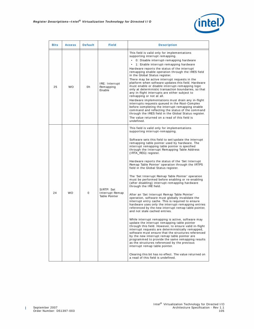
Intel® Virtualization Technology for Directed I/OSeptember 2007 Architecture Specification - Rev 1.1Order Number: D51397-003 105
Register Descriptions—Intel® Virtualization Technology for Directed I/O
25 WO 0hIRE: Interrupt Remapping Enable
This field is valid only for implementations supporting interrupt remapping.• 0: Disable interrupt-remapping hardware• 1: Enable interrupt-remapping hardware
Hardware reports the status of the interrupt remapping enable operation through the IRES field in the Global Status register.There may be active interrupt requests in the platform when software updates this field. Hardware must enable or disable interrupt-remapping logic only at deterministic transaction boundaries, so that any in-flight interrupts are either subject to remapping or not at all.Hardware implementations must drain any in-flight interrupts requests queued in the Root-Complex before completing the interrupt-remapping enable command and reflecting the status of the command through the IRES field in the Global Status register.The value returned on a read of this field is undefined.
24 WO 0SIRTP: Set Interrupt Remap Table Pointer
This field is valid only for implementations supporting interrupt-remapping.
Software sets this field to set/update the interrupt remapping table pointer used by hardware. The interrupt remapping table pointer is specified through the Interrupt Remapping Table Address (IRTA_REG) register.
Hardware reports the status of the ‘Set Interrupt Remap Table Pointer’ operation through the IRTPS field in the Global Status register.
The ‘Set Interrupt Remap Table Pointer’ operation must be performed before enabling or re-enabling (after disabling) interrupt-remapping hardware through the IRE field.
After an ‘Set Interrupt Remap Table Pointer’ operation, software must globally invalidate the interrupt entry cache. This is required to ensure hardware uses only the interrupt-remapping entries referenced by the new interrupt remap table pointer, and not stale cached entries.
While interrupt remapping is active, software may update the interrupt remapping table pointer through this field. However, to ensure valid in-flight interrupt requests are deterministically remapped, software must ensure that the structures referenced by the new interrupt remap table pointer are programmed to provide the same remapping results as the structures referenced by the previous interrupt remap table pointer.
Clearing this bit has no effect. The value returned on a read of this field is undefined.
Bits Access Default Field Description
Intel® Virtualization Technology for Directed I/O—Register Descriptions
Intel® Virtualization Technology for Directed I/OArchitecture Specification - Rev 1.1 September 2007106 Order Number: D51397-003
23 WO 0CFI: Compatibility Format Interrupt
This field is valid only for Intel®64 implementations supporting interrupt-remapping.
Software writes to this field to enable or disable Compatibility Format interrupts on Intel®64 platforms. The value in this field is effective only when interrupt-remapping is enabled and Extended Interrupt Mode (x2APIC mode) is not enabled.• 0: Block Compatibility format interrupts.• 1: Process Compatibility format interrupts as
pass-through (bypass interrupt remapping).
Hardware reports the status of updating this field through the CFIS field in the Global Status register.
Refer to Section 5.3.1 for details on Compatibility Format interrupt requests.
The value returned on a read of this field is undefined.
This field is not implemented on ItaniumTM implementations.
22:0 RsvdZ 0h R: Reserved Reserved.
1. Implementations reporting write-buffer flushing as required in Capability register must perform implicitwrite buffer flushing as a pre-condition to all context-cache and IOTLB invalidation operations.
Bits Access Default Field Description

Intel® Virtualization Technology for Directed I/OSeptember 2007 Architecture Specification - Rev 1.1Order Number: D51397-003 107
Register Descriptions—Intel® Virtualization Technology for Directed I/O
10.4.5 Global Status Register
Figure 10-33. Global Status Register
Abbreviation GSTS_REG
General Description Register to report general remapping hardware status.
Register Offset 01Ch
Bits Access Default Field Description
31 RO 0 TES: Translation Enable Status
This field indicates the status of DMA-remapping hardware.• 0: DMA remapping is not enabled• 1: DMA remapping is enabled
30 RO 0 RTPS: Root Table Pointer Status
This field indicates the status of the root-table pointer in hardware.
This field is cleared by hardware when software sets the SRTP field in the Global Command register. This field is set by hardware when hardware completes the ‘Set Root Table Pointer’ operation using the value provided in the Root-Entry Table Address register.
29 RO 0 FLS: Fault Log Status
This field:• Is cleared by hardware when software Sets the
SFL field in the Global Command register. • Is Set by hardware when hardware completes
the ‘Set Fault Log Pointer’ operation using the value provided in the Advanced Fault Log register.
28 RO 0AFLS: Advanced Fault Logging Status
This field is valid only for implementations supporting advanced fault logging. It indicates the advanced fault logging status:• 0: Advanced Fault Logging is not enabled• 1: Advanced Fault Logging is enabled
27 RO 0WBFS: Write Buffer Flush Status
This field is valid only for implementations requiring write buffer flushing. This field indicates the status of the write buffer flush command. It is • Set by hardware when software sets the WBF
field in the Global Command register. • Cleared by hardware when hardware completes
the write buffer flushing operation.
26 RO 0QIES: Queued Invalidation Enable Status
This field indicates queued invalidation enable status. • 0: queued invalidation is not enabled• 1: queued invalidation is enabled
Rsvd
023
IRTPSIRESQIESWBFSAFLSFLSRTPSTES
31
30
29
28
27
26
25
24
CFIS
22

Intel® Virtualization Technology for Directed I/O—Register Descriptions
Intel® Virtualization Technology for Directed I/OArchitecture Specification - Rev 1.1 September 2007108 Order Number: D51397-003
25 RO 0IRES: Interrupt Remapping Enable Status
This field indicates the status of Interrupt-remapping hardware.• 0: Interrupt-remapping hardware is not enabled• 1:Interrupt-remapping hardware is enabled
24RO
0IRTPS: Interrupt Remapping Table Pointer Status
This field indicates the status of the interrupt remapping table pointer in hardware.
This field is cleared by hardware when software sets the SIRTP field in the Global Command register. This field is Set by hardware when hardware completes the ‘Set Interrupt Remap Table Pointer’ operation using the value provided in the Interrupt Remapping Table Address register.
23 RO 0
CFIS: Compatibility Format Interrupt Status
This field indicates the status of Compatibility format interrupts on Intel®64 implementations supporting interrupt-remapping. The value reported in this field is applicable only when interrupt-remapping is enabled and extended interrupt mode (x2APIC mode) is not enabled.• 0: Compatibility format interrupts are blocked.• 1: Compatibility format interrupts are processed
as pass-through (bypassing interrupt remapping).
22:0 RsvdZ 0h R: Reserved Reserved.
Bits Access Default Field Description

Intel® Virtualization Technology for Directed I/OSeptember 2007 Architecture Specification - Rev 1.1Order Number: D51397-003 109
Register Descriptions—Intel® Virtualization Technology for Directed I/O
10.4.6 Root-Entry Table Address Register
Figure 10-34. Root-Entry Table Address Register
Abbreviation RTADDR_REG
GeneralDescription Register providing the base address of root-entry table.
Register Offset 020h
Bits Access Default Field Description
63:12 RW 0h RTA: Root Table Address
This register points to the base of the page-aligned, 4KB-sized root-entry table in system memory. Hardware ignores and not implement bits 63:HAW, where HAW is the host address width.
Software specifies the base address of the root-entry table through this register, and programs it in hardware through the SRTP field in the Global Command register.
Reads of this register return the value that was last programmed to it.
11:0 RsvdZ 0h R: Reserved Reserved.
RTA
063
12
11
Rsvd

Intel® Virtualization Technology for Directed I/O—Register Descriptions
Intel® Virtualization Technology for Directed I/OArchitecture Specification - Rev 1.1 September 2007110 Order Number: D51397-003
10.4.7 Context Command Register
Figure 10-35. Context Command Register
Abbreviation CCMD_REG
GeneralDescription
Register to manage context cache.The act of writing the uppermost byte of the CCMD_REG with the ICC field Set causes the hardware to perform the context-cache invalidation.
Register Offset 028h
Bits Access Default Field Description
63 RW 0ICC: InvalidateContext-Cache
Software requests invalidation of context-cache by setting this field. Software must also set the requested invalidation granularity by programming the CIRG field. Software must read back and check the ICC field is Clear to confirm the invalidation is complete. Software must not update this register when this field is Set.
Hardware clears the ICC field to indicate the invalidation request is complete.Hardware also indicates the granularity at which the invalidation operation was performed through the CAIG field.
Software must submit a context-cache invalidation request through this field only when there are no invalidation requests pending at this remapping hardware unit. Refer to Chapter 11 for software programming requirements.
Since information from the context-cache may be used by hardware to tag IOTLB entries, software must perform domain-selective (or global) invalidation of IOTLB after the context cache invalidation has completed.
Hardware implementations reporting a write-buffer flushing requirement (RWBF=1 in the Capability register) must implicitly perform a write buffer flush before invalidating the context-cache. Refer to Section 11.1 for write buffer flushing requirements.
0
FM DID
16
15
SIDRsvdCAIGCIRGICC
31
32
33
34
63
62
61
60
59
58

Intel® Virtualization Technology for Directed I/OSeptember 2007 Architecture Specification - Rev 1.1Order Number: D51397-003 111
Register Descriptions—Intel® Virtualization Technology for Directed I/O
62:61 RW 0h
CIRG: ContextInvalidation Request Granularity
Software provides the requested invalidation granularity through this field when setting the ICC field:• 00: Reserved. • 01: Global Invalidation request.• 10: Domain-selective invalidation request. The
target domain-id must be specified in the DID field.
• 11: Device-selective invalidation request. The target source-id(s) must be specified through the SID and FM fields, and the domain-id [that was programmed in the context-entry for these device(s)] must be provided in the DID field.
Hardware implementations may process an invalidation request by performing invalidation at a coarser granularity than requested. Hardware indicates completion of the invalidation request by clearing the ICC field. At this time, hardware also indicates the granularity at which the actual invalidation was performed through the CAIG field.
60:59 RO Xh
CAIG: ContextActual Invalidation Granularity
Hardware reports the granularity at which an invalidation request was processed through the CAIG field at the time of reporting invalidation completion (by clearing the ICC field).
The following are the encodings for this field:• 00: Reserved. • 01: Global Invalidation performed. This could be
in response to a global, domain-selective, or device-selective invalidation request.
• 10: Domain-selective invalidation performed using the domain-id specified by software in the DID field. This could be in response to a domain-selective or device-selective invalidation request.
• 11: Device-selective invalidation performed using the source-id and domain-id specified by software in the SID and FM fields. This can only be in response to a device-selective invalidation request.
58:34 RsvdZ 0h R: Reserved Reserved.
33:32 WO 0h FM: Function Mask
Software may use the Function Mask to perform device-selective invalidations on behalf of devices supporting PCI Express Phantom Functions. This field specifies which bits of the function number portion (least significant three bits) of the SID field to mask when performing device-selective invalidations.The following encodings are defined for this field:• 00: No bits in the SID field masked• 01: Mask bit 2 in the SID field• 10: Mask bits 2:1 in the SID field• 11: Mask bits 2:0 in the SID field
The context-entries corresponding to the source-ids specified through the SID and FM fields must have the domain-id specified in the DID field.
The value returned on a read of this field is undefined.
Bits Access Default Field Description

Intel® Virtualization Technology for Directed I/O—Register Descriptions
Intel® Virtualization Technology for Directed I/OArchitecture Specification - Rev 1.1 September 2007112 Order Number: D51397-003
31:16 WO 0h SID: Source-ID
Indicates the source-id of the device whose corresponding context-entry needs to be selectively invalidated.This field along with the FM field must be programmed by software for device-selective invalidation requests.
The value returned on a read of this field is undefined.
15:0 RW 0h DID: Domain-ID
Indicates the id of the domain whose context-entries need to be selectively invalidated. This field must be programmed by software for both domain-selective and device-selective invalidation requests.
The Capability register reports the domain-id width supported by hardware. Software must ensure that the value written to this field is within this limit. Hardware ignores (and may not implement) bits 15:N, where N is the supported domain-id width reported in the Capability register.
Bits Access Default Field Description

Intel® Virtualization Technology for Directed I/OSeptember 2007 Architecture Specification - Rev 1.1Order Number: D51397-003 113
Register Descriptions—Intel® Virtualization Technology for Directed I/O
10.4.8 IOTLB Registers
IOTLB registers consists of two adjacently placed 64-bit registers:
• IOTLB Invalidate Register (IOTLB_REG)
• Invalidate Address Register (IVA_REG)
These registers are described in the following sub-sections.
Offset Register Name Size Description
XXXh Invalidate Address Register 64
Register to provide the target address for page-selective IOTLB invalidation. The offset of this register is reported through the IVO field in Extended Capability register.
XXXh + 008h IOTLB Invalidate Register 64 Register for IOTLB invalidation command

Intel® Virtualization Technology for Directed I/O—Register Descriptions
Intel® Virtualization Technology for Directed I/OArchitecture Specification - Rev 1.1 September 2007114 Order Number: D51397-003
10.4.8.1 IOTLB Invalidate Register
Figure 10-36. IOTLB Invalidate Register
Abbreviation IOTLB_REG
General Description
Register to invalidate IOTLB. The act of writing the upper byte of the IOTLB_REG with the IVT field Set causes the hardware to perform the IOTLB invalidation.
Register Offset XXXh + 0008h (where XXXh is the location of the IVA_REG)
Bits Access Default Field Description
63 RW 0 IVT: Invalidate IOTLB
Software requests IOTLB invalidation by setting this field. Software must also set the requested invalidation granularity by programming the IIRG field.
Hardware clears the IVT field to indicate the invalidation request is complete. Hardware also indicates the granularity at which the invalidation operation was performed through the IAIG field. Software must not submit another invalidation request through this register while the IVT field is Set, nor update the associated Invalidate Address register.
Software must not submit IOTLB invalidation requests when there is a context-cache invalidation request pending at this remapping hardware unit. Refer to Chapter 11 for software programming requirements.
Hardware implementations reporting a write-buffer flushing requirement (RWBF=1 in Capability register) must implicitly perform a write buffer flushing before invalidating the IOTLB. Refer to Section 11.1 for write buffer flushing requirements.
0
DR Rsvd
31
DIDRsvdIAIGIIRGIVT
32
47
48
49
63
62
60
59
57
56
DW
50

Intel® Virtualization Technology for Directed I/OSeptember 2007 Architecture Specification - Rev 1.1Order Number: D51397-003 115
Register Descriptions—Intel® Virtualization Technology for Directed I/O
62:60 RW 0h
IIRG: IOTLB Invalidation Request Granularity
When requesting hardware to invalidate the IOTLB (by setting the IVT field), software writes the requested invalidation granularity through this field. The following are the encodings for the field. • 000: Reserved.• 001: Global invalidation request.• 010: Domain-selective invalidation request. The
target domain-id must be specified in the DID field.
• 011: Page-selective invalidation request. The target address, mask, and invalidation hint must be specified in the Invalidate Address register, and the domain-id must be provided in the DID field.
• 101 - 111: Reserved.
Hardware implementations may process an invalidation request by performing invalidation at a coarser granularity than requested. Hardware indicates completion of the invalidation request by clearing the IVT field. At that time, the granularity at which actual invalidation was performed is reported through the IAIG field.
59:57 RO Xh
IAIG: IOTLB Actual Invalidation Granularity
Hardware reports the granularity at which an invalidation request was processed through this field when reporting invalidation completion (by clearing the IVT field).
The following are the encodings for this field.• 000: Reserved. This indicates hardware detected
an incorrect invalidation request and ignored the request. Examples of incorrect invalidation requests include detecting an unsupported address mask value in Invalidate Address register for page-selective invalidation requests.
• 001: Global Invalidation performed. This could be in response to a global, domain-selective, or page-selective invalidation request.
• 010: Domain-selective invalidation performed using the domain-id specified by software in the DID field. This could be in response to a domain-selective or a page-selective invalidation request.
• 011: Domain-page-selective invalidation performed using the address, mask and hint specified by software in the Invalidate Address register and domain-id specified in DID field. This can be in response to a page-selective invalidation request.
• 100 - 111: Reserved.
56:50 RsvdZ 0h R: Reserved Reserved.
49 RW 0h DR: Drain Reads
This field is ignored by hardware if the DRD field is reported as Clear in the Capability register. When the DRD field is reported as Set in the Capability register, the following encodings are supported for this field:• 0: Hardware may complete the IOTLB
invalidation without draining DMA read requests.• 1: Hardware must drain DMA read requests.
Refer Section 6.3 for description of DMA draining.
Bits Access Default Field Description
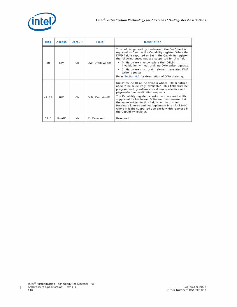
Intel® Virtualization Technology for Directed I/O—Register Descriptions
Intel® Virtualization Technology for Directed I/OArchitecture Specification - Rev 1.1 September 2007116 Order Number: D51397-003
48 RW 0h DW: Drain Writes
This field is ignored by hardware if the DWD field is reported as Clear in the Capability register. When the DWD field is reported as Set in the Capability register, the following encodings are supported for this field:• 0: Hardware may complete the IOTLB
invalidation without draining DMA write requests.• 1: Hardware must drain relevant translated DMA
write requests.Refer Section 6.3 for description of DMA draining.
47:32 RW 0h DID: Domain-ID
Indicates the ID of the domain whose IOTLB entries need to be selectively invalidated. This field must be programmed by software for domain-selective and page-selective invalidation requests.The Capability register reports the domain-id width supported by hardware. Software must ensure that the value written to this field is within this limit. Hardware ignores and not implement bits 47:(32+N), where N is the supported domain-id width reported in the Capability register.
31:0 RsvdP Xh R: Reserved Reserved.
Bits Access Default Field Description

Intel® Virtualization Technology for Directed I/OSeptember 2007 Architecture Specification - Rev 1.1Order Number: D51397-003 117
Register Descriptions—Intel® Virtualization Technology for Directed I/O
10.4.8.2 Invalidate Address Register
Figure 10-37. Invalidate Address Register
Abbreviation IVA_REG
General Description
Register to provide the DMA address whose corresponding IOTLB entry needs to be invalidated through the corresponding IOTLB Invalidate register. This register is a write-only register. A value returned on a read of this register is undefined.
Register Offset XXXh (XXXh is QWORD aligned and reported through the IVO field in the Extended Capability register)
Bits Access Default Field Description
63:12 WO 0h ADDR: Address
Software provides the DMA address that needs to be page-selectively invalidated. To make a page-selective invalidation request to hardware, software must first write the appropriate fields in this register, and then issue the appropriate page-selective invalidate command through the IOTLB_REG. Hardware ignores bits 63:N, where N is the maximum guest address width (MGAW) supported.
A value returned on a read of this field is undefined.
11:7 RsvdZ 0 R: Reserved Reserved.
6 WO 0 IH: Invalidation Hint
The field provides hints to hardware about preserving or flushing the non-leaf (page-directory) entries that may be cached in hardware: • 0: Software may have modified both leaf and
non-leaf page-table entries corresponding to mappings specified in the ADDR and AM fields. On a page-selective invalidation request, hardware must flush both the cached leaf and non-leaf page-table entries corresponding to the mappings specified by ADDR and AM fields.
• 1: Software has not modified any non-leaf page-table entries corresponding to mappings specified in the ADDR and AM fields. On a page-selective invalidation request, hardware may preserve the cached non-leaf page-table entries corresponding to the mappings specified by the ADDR and AM fields.
A value returned on a read of this field is undefined.
0
ADDR Rsvd
63
12
11
IH AM
567
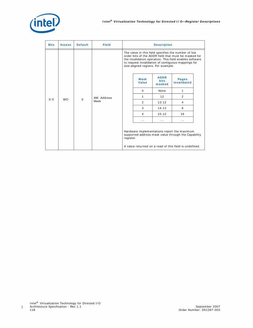
Intel® Virtualization Technology for Directed I/O—Register Descriptions
Intel® Virtualization Technology for Directed I/OArchitecture Specification - Rev 1.1 September 2007118 Order Number: D51397-003
5:0 WO 0 AM: Address Mask
The value in this field specifies the number of low order bits of the ADDR field that must be masked for the invalidation operation. This field enables software to request invalidation of contiguous mappings for size-aligned regions. For example:
Hardware implementations report the maximum supported address mask value through the Capability register.
A value returned on a read of this field is undefined.
Bits Access Default Field Description
Mask Value
ADDR bits
masked
Pages invalidated
0 None 1
1 12 2
2 13:12 4
3 14:12 8
4 15:12 16
... ... ...

Intel® Virtualization Technology for Directed I/OSeptember 2007 Architecture Specification - Rev 1.1Order Number: D51397-003 119
Register Descriptions—Intel® Virtualization Technology for Directed I/O
10.4.9 Fault Status Register
Figure 10-38. Fault Status Register
Abbreviation FSTS_REG
GeneralDescription Register indicating the various error status.
Register Offset 034h
Bits Access Default Field Description
31:16 RsvdZ 0h R: Reserved Reserved.
15:8 ROS 0 FRI: Fault Record Index
This field is valid only when the PPF field is Set.
The FRI field indicates the index (from base) of the fault recording register to which the first pending fault was recorded when the PPF field was Set by hardware.
The value read from this field is undefined when the PPF field is Clear.
7 RsvdZ 0h R: Reserved Reserved.
6 RW1CS 0h ITE: Invalidation Time-out Error
Hardware detected a Device-IOTLB invalidation completion time-out. At this time, a fault event may be generated based on the programming of the Fault Event Control register.
Hardware implementations not supporting Device-IOTLBs implement this bit as RsvdZ.
5 RW1CS 0h ICE: Invalidation Completion Error
Hardware received an unexpected or invalid Device-IOTLB invalidation completion. This could be due to either an invalid ITag or invalid source-id in an invalidation completion response. At this time, a fault event may be generated based on the programming of the Fault Event Control register.
Hardware implementations not supporting Device-IOTLBs implement this bit as RsvdZ.
4 RW1CS 0 IQE: Invalidation Queue Error
Hardware detected an error associated with the invalidation queue. This could be due to either a hardware error while fetching a descriptor from the invalidation queue, or hardware detecting an erroneous or invalid descriptor in the invalidation queue. At this time, a fault event may be generated based on the programming of the Fault Event Control register.
Hardware implementations not supporting queued invalidations implement this bit as RsvdZ.
012347 6 5
PFOPPFAFOAPFIQEICEITEFRIRsvd Rsvd
815
16
31
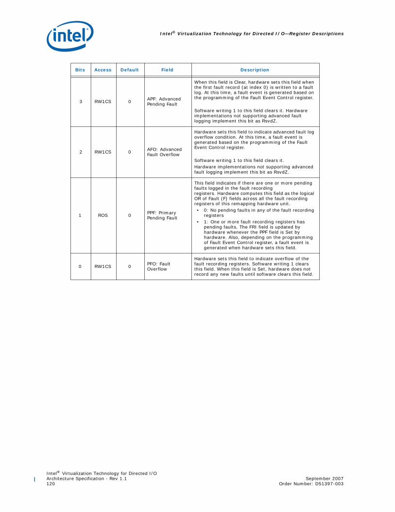
Intel® Virtualization Technology for Directed I/O—Register Descriptions
Intel® Virtualization Technology for Directed I/OArchitecture Specification - Rev 1.1 September 2007120 Order Number: D51397-003
3 RW1CS 0 APF: Advanced Pending Fault
When this field is Clear, hardware sets this field when the first fault record (at index 0) is written to a fault log. At this time, a fault event is generated based on the programming of the Fault Event Control register.
Software writing 1 to this field clears it. Hardware implementations not supporting advanced fault logging implement this bit as RsvdZ.
2 RW1CS 0 AFO: Advanced Fault Overflow
Hardware sets this field to indicate advanced fault log overflow condition. At this time, a fault event is generated based on the programming of the Fault Event Control register.
Software writing 1 to this field clears it.Hardware implementations not supporting advanced fault logging implement this bit as RsvdZ.
1 ROS 0 PPF: Primary Pending Fault
This field indicates if there are one or more pending faults logged in the fault recording registers. Hardware computes this field as the logical OR of Fault (F) fields across all the fault recording registers of this remapping hardware unit. • 0: No pending faults in any of the fault recording
registers• 1: One or more fault recording registers has
pending faults. The FRI field is updated by hardware whenever the PPF field is Set by hardware. Also, depending on the programming of Fault Event Control register, a fault event is generated when hardware sets this field.
0 RW1CS 0 PFO: Fault Overflow
Hardware sets this field to indicate overflow of the fault recording registers. Software writing 1 clears this field. When this field is Set, hardware does not record any new faults until software clears this field.
Bits Access Default Field Description

Intel® Virtualization Technology for Directed I/OSeptember 2007 Architecture Specification - Rev 1.1Order Number: D51397-003 121
Register Descriptions—Intel® Virtualization Technology for Directed I/O
10.4.10 Fault Event Control Register
Figure 10-39. Fault Event Control Register
Abbreviation FECTL_REG
General Description
Register specifying the fault event interrupt message control bits. Section 7.3 describes hardware handling of fault events.
Register Offset 038h
Bits Access Default Field Description
31 RW 1 IM: Interrupt Mask
• 0: No masking of interrupts. When a interrupt condition is detected, hardware issues an interrupt message (using the Fault Event Data and Fault Event Address register values).
• 1: This is the value on reset. Software may mask interrupt message generation by setting this field.Hardware is prohibited from sending the interrupt message when this field is Set.
IM
0
IP Rsvd
31
30
29

Intel® Virtualization Technology for Directed I/O—Register Descriptions
Intel® Virtualization Technology for Directed I/OArchitecture Specification - Rev 1.1 September 2007122 Order Number: D51397-003
30 RO 0 IP: Interrupt Pending
Hardware sets the IP field whenever it detects an interrupt condition, which is defined as:• When primary fault logging is active, an
interrupt condition occurs when hardware records a fault through one of the Fault Recording registers and sets the PPF field in the Fault Status register.
• When advanced fault logging is active, an interrupt condition occurs when hardware records a fault in the first fault record (at index 0) of the current fault log and sets the APF field in the Fault Status register.
• Hardware detected error associated with the Invalidation Queue, setting the IQE field in the Fault Status register.
• Hardware detected invalid Device-IOTLB invalidation completion, setting the ICE field in the Fault Status register.
• Hardware detected Device-IOTLB invalidation completion time-out, setting the ITE field in the Fault Status register.
If any of the status fields in the Fault Status register was already Set at the time of setting any of these fields, it is not treated as a new interrupt condition.
The IP field is kept Set by hardware while the interrupt message is held pending. The interrupt message could be held pending due to the interrupt mask (IM field) being Set or other transient hardware conditions.
The IP field is cleared by hardware as soon as the interrupt message pending condition is serviced. This could be due to either:• Hardware issuing the interrupt message due to
either a change in the transient hardware condition that caused the interrupt message to be held pending, or due to software clearing the IM field.
• Software servicing all the pending interrupt status fields in the Fault Status register as follows.• When primary fault logging is active,
software clearing the Fault (F) field in all the Fault Recording registers with faults, causing the PPF field in the Fault Status register to be evaluated as Clear.
• Software clearing other status fields in the Fault Status register by writing back the value read from the respective fields.
29:0 RsvdP Xh R: Reserved Reserved.
Bits Access Default Field Description

Intel® Virtualization Technology for Directed I/OSeptember 2007 Architecture Specification - Rev 1.1Order Number: D51397-003 123
Register Descriptions—Intel® Virtualization Technology for Directed I/O
10.4.11 Fault Event Data Register
Figure 10-40. Fault Event Data Register
Abbreviation FEDATA_REG
General Description Register specifying the interrupt message data.
Register Offset 03Ch
Bits Access Default Field Description
31:16 RW 0hEIMD: Extended Interrupt Message Data
This field is valid only for implementations supporting 32-bit interrupt data fields.
Hardware implementations supporting only 16-bit interrupt data treat this field as RsvdZ.
15:0 RW 0h IMD: Interrupt Message data
Data value in the interrupt request. Software requirements for programming this register are described in Section 5.6.
EIMD
0
IMD
31
16
15

Intel® Virtualization Technology for Directed I/O—Register Descriptions
Intel® Virtualization Technology for Directed I/OArchitecture Specification - Rev 1.1 September 2007124 Order Number: D51397-003
10.4.12 Fault Event Address Register
Figure 10-41. Fault Event Address Register
Abbreviation FEADDR_REG
General Description Register specifying the interrupt message address.
Register Offset 040h
Bits Access Default Field Description
31:2 RW 0h MA: Message address
When fault events are enabled, the contents of this register specify the DWORD-aligned address (bits 31:2) for the interrupt request.
Software requirements for programming this register are described in Section 5.6.
1:0 RsvdZ 0h R: Reserved Reserved.
0
RsvdMA
31 12

Intel® Virtualization Technology for Directed I/OSeptember 2007 Architecture Specification - Rev 1.1Order Number: D51397-003 125
Register Descriptions—Intel® Virtualization Technology for Directed I/O
10.4.13 Fault Event Upper Address Register
Figure 10-42. Fault Event Upper Address Register
Abbreviation FEUADDR_REG
General Description Register specifying the interrupt message upper address.
Register Offset 044h
Bits Access Default Field Description
31:0 RW 0h MUA: Message upper address
Hardware implementations supporting Extended Interrupt Mode are required to implement this register.
Software requirements for programming this register are described in Section 5.6.
Hardware implementations not supporting Extended Interrupt Mode may treat this field as RsvdZ.
0
MUA
31

Intel® Virtualization Technology for Directed I/O—Register Descriptions
Intel® Virtualization Technology for Directed I/OArchitecture Specification - Rev 1.1 September 2007126 Order Number: D51397-003
10.4.14 Fault Recording Registers [n]
Figure 10-43. Fault Recording Register
Abbreviation FRCD_REG [n]
General Description
Registers to record fault information when primary fault logging is active.Hardware reports the number and location of fault recording registers through the Capability register. This register is relevant only for primary fault logging.
These registers are sticky and can be cleared only through power good reset or by software clearing the RW1C fields by writing a 1.
Register Offset YYYh (YYYh must be 128-bit aligned)
Bits Access Default Field Description
127 RW1CS 0 F: Fault1
Hardware sets this field to indicate a fault is logged in this Fault Recording register. The F field is Set by hardware after the details of the fault is recorded in other fields.
When this field is Set, hardware may collapse additional faults from the same source-id (SID).
Software writes the value read from this field to Clear it.
Refer to Section 7.2.1 for hardware details of primary fault logging.
126 ROS X T: Type
Type of the faulted request: • 0: Write request• 1: Read request
This field is relevant only when the F field is Set, and when the fault reason (FR) indicates one of the DMA-remapping fault conditions.
0
Rsvd
FR SID
FI
RsvdRsvdATTF
63
127
64
124
126
125
123
104
103
96
95
80
79
11
12

Intel® Virtualization Technology for Directed I/OSeptember 2007 Architecture Specification - Rev 1.1Order Number: D51397-003 127
Register Descriptions—Intel® Virtualization Technology for Directed I/O
125:124 ROS Xh AT: Address Type
This field captures the AT field from the faulted DMA request. Hardware implementations not supporting Device-IOTLBs (DI field Clear in Extended Capability register) treat this field as RsvdZ. When supported, this field is valid only when the F field is Set, and when the fault reason (FR) indicates one of the DMA-remapping fault conditions.
123:104 RsvdZ 0h R: Reserved Reserved.
103:96 ROS Xh FR: Fault Reason
Reason for the fault. Appendix A enumerates the various translation fault reason encodings.
This field is relevant only when the F field is Set.
95:80 RsvdZ 0h R: Reserved Reserved.
79:64 ROS Xh SID: Source Identifier
Requester-id associated with the fault condition.This field is relevant only when the F field is Set.
63:12 ROS Xh FI: Fault Info
When the Fault Reason (FR) field indicates one of the DMA-remapping fault conditions, bits 63:12 of this field contains the page address in the faulted DMA request. Hardware treat bits 63:N as reserved (0), where N is the maximum guest address width (MGAW) supported.
When the Fault Reason (FR) field indicates one of the interrupt-remapping fault conditions, bits 63:48 of this field indicate the interrupt_index computed for the faulted interrupt request, and bits 47:12 are cleared.
This field is relevant only when the F field is Set.
11:0 RsvdZ 0h R: Reserved Reserved.
1. Hardware updates to this register may be disassembled as multiple doubleword writes. To ensure consistentdata is read from this register, software must first check the Primary Pending Fault (PPF) field in theFSTS_REG is Set before reading the fault reporting register at offset as indicated in the FRI field ofFSTS_REG. Alternatively, software may read the highest doubleword in a fault recording register and checkif the Fault (F) field is Set before reading the rest of the data fields in that register.
Bits Access Default Field Description

Intel® Virtualization Technology for Directed I/O—Register Descriptions
Intel® Virtualization Technology for Directed I/OArchitecture Specification - Rev 1.1 September 2007128 Order Number: D51397-003
10.4.15 Advanced Fault Log Register
Figure 10-44. Advanced Fault Log Register
Abbreviation AFLOG_REG
General Description
Register to specify the base address of the memory-resident fault-log region. This register is treated as RsvdZ for implementations not supporting advanced translation fault logging (AFL field reported as 0 in the Capability register).
Register Offset 058h
Bits Access Default Field Description
63:12 RW 0h FLA: Fault Log Address
This field specifies the base of 4KB aligned fault-log region in system memory. Hardware ignores and not implement bits 63:HAW, where HAW is the host address width.
Software specifies the base address and size of the fault log region through this register, and programs it in hardware through the SFL field in the Global Command register. When implemented, reads of this field return the value that was last programmed to it.
11:9 RW 0h FLS: Fault Log Size
This field specifies the size of the fault log region pointed by the FLA field. The size of the fault log region is 2X * 4KB, where X is the value programmed in this register.
When implemented, reads of this field return the value that was last programmed to it.
8:0 RsvdZ 0h R: Reserved Reserved.
0
FLA Rsvd
63
12 8
FLS
911

Intel® Virtualization Technology for Directed I/OSeptember 2007 Architecture Specification - Rev 1.1Order Number: D51397-003 129
Register Descriptions—Intel® Virtualization Technology for Directed I/O
10.4.16 Protected Memory Enable Register
Figure 10-45. Protected Memory Enable Register
Abbreviation PMEN_REG
General Description
Register to enable the DMA-protected memory regions set up through the PLMBASE, PLMLIMT, PHMBASE, PHMLIMIT registers. This register is always treated as RO for implementations not supporting protected memory regions (PLMR and PHMR fields reported as Clear in the Capability register).
Protected memory regions may be used by software to securely initialize remapping structures in memory.
Register Offset 064h
Rsvd
0
PRSEPM
31
30 1

Intel® Virtualization Technology for Directed I/O—Register Descriptions
Intel® Virtualization Technology for Directed I/OArchitecture Specification - Rev 1.1 September 2007130 Order Number: D51397-003
Bits Access Default Field Description
31 RW 0hEPM: Enable Protected Memory
This field controls DMA accesses to the protected low-memory and protected high-memory regions. • 0: Protected memory regions are disabled.• 1: Protected memory regions are enabled.
DMA requests accessing protected memory regions are handled as follows:• When DMA remapping is not enabled, all
DMA requests accessing protected memory regions are blocked.
• When DMA remapping is enabled:
• DMA requests processed as pass-through (Translation Type value of 10b in Context-Entry) and accessing the protected memory regions are blocked.
• DMA requests with translated address (AT=10b) and accessing the protected memory regions are blocked.
• DMA requests that are subject to address remapping, and accessing the protected memory regions may or may not be blocked by hardware. For such requests, software must not depend on hardware protection of the protected memory regions, and instead program the DMA-remapping page-tables to block DMA to protected memory regions.
Remapping hardware access to the remapping structures are not subject to protected memory region checks.
DMA requests blocked due to protected memory region violation are not recorded or reported as remapping faults.
Hardware reports the status of the protected memory enable/disable operation through the PRS field in this register. Hardware implementations supporting DMA draining must drain any in-flight translated DMA requests queued within the Root-Complex before indicating the protected memory region as enabled through the PRS field.
30:1 RsvdP Xh R: Reserved Reserved.
0 RO 0h PRS: Protected Region Status
This field indicates the status of protected memory region(s): • 0: Protected memory region(s) disabled.• 1: Protected memory region(s) enabled.

Intel® Virtualization Technology for Directed I/OSeptember 2007 Architecture Specification - Rev 1.1Order Number: D51397-003 131
Register Descriptions—Intel® Virtualization Technology for Directed I/O
10.4.17 Protected Low-Memory Base Register
Figure 10-46. Protected Low-Memory Base Register
Abbreviation PLMBASE_REG
General Description
Register to set up the base address of DMA-protected low-memory region below 4GB. This register must be set up before enabling protected memory through PMEN_REG, and must not be updated when protected memory regions are enabled.
This register is always treated as RO for implementations not supporting protected low memory region (PLMR field reported as Clear in the Capability register).
The alignment of the protected low memory region base depends on the number of reserved bits (N:0) of this register. Software may determine N by writing all 1s to this register, and finding the most significant bit position with 0 in the value read back from the register. Bits N:0 of this register are decoded by hardware as all 0s.
Software must setup the protected low memory region below 4GB. Section 10.4.18 describes the Protected Low-Memory Limit register and hardware decoding of these registers.
Software must not modify this register when protected memory regions are enabled (PRS field Set in PMEN_REG)
Register Offset 068h
Bits Access Default Field Description
31:(N+1) RW 0hPLMB: Protected Low-Memory Base
This register specifies the base of protected low-memory region in system memory.
N:0 RsvdZ 0h R: Reserved Reserved.
0
Rsvd
31 N
PLMB

Intel® Virtualization Technology for Directed I/O—Register Descriptions
Intel® Virtualization Technology for Directed I/OArchitecture Specification - Rev 1.1 September 2007132 Order Number: D51397-003
10.4.18 Protected Low-Memory Limit Register
Figure 10-47. Protected Low-Memory Limit Register
Abbreviation PLMLIMIT_REG
General Description
Register to set up the limit address of DMA-protected low-memory region below 4GB. This register must be set up before enabling protected memory through PMEN_REG, and must not be updated when protected memory regions are enabled.
This register is always treated as RO for implementations not supporting protected low memory region (PLMR field reported as Clear in the Capability register).
The alignment of the protected low memory region limit depends on the number of reserved bits (N:0) of this register. Software may determine N by writing all 1’s to this register, and finding most significant zero bit position with 0 in the value read back from the register. Bits N:0 of the limit register are decoded by hardware as all 1s.
The Protected low-memory base and limit registers function as follows:• Programming the protected low-memory base and limit registers the same
value in bits 31:(N+1) specifies a protected low-memory region of size 2(N+1) bytes.
• Programming the protected low-memory limit register with a value less than the protected low-memory base register disables the protected low-memory region.
Software must not modify this register when protected memory regions are enabled (PRS field Set in PMEN_REG)
Register Offset 06Ch
Bits Access Default Field Description
31:(N+1) RW 0hPLML: Protected Low-Memory Limit
This register specifies the last host physical address of the DMA-protected low-memory region in system memory.
N:0 RsvdZ 0h R: Reserved Reserved.
0
Rsvd
31 N
PLML

Intel® Virtualization Technology for Directed I/OSeptember 2007 Architecture Specification - Rev 1.1Order Number: D51397-003 133
Register Descriptions—Intel® Virtualization Technology for Directed I/O
10.4.19 Protected High-Memory Base Register
Figure 10-48. Protected High-Memory Base Register
Abbreviation PHMBASE_REG
General Description
Register to set up the base address of DMA-protected high-memory region. This register must be set up before enabling protected memory through PMEN_REG, and must not be updated when protected memory regions are enabled.
This register is always treated as RO for implementations not supporting protected high memory region (PHMR field reported as Clear in the Capability register).
The alignment of the protected high memory region base depends on the number of reserved bits (N:0) of this register. Software may determine N by writing all 1’s to this register, and finding most significant zero bit position below host address width (HAW) in the value read back from the register. Bits N:0 of this register are decoded by hardware as all 0s.
Software may setup the protected high memory region either above or below 4GB. Section 10.4.20 describes the Protected High-Memory Limit register and hardware decoding of these registers.
Software must not modify this register when protected memory regions are enabled (PRS field Set in PMEN_REG)
Register Offset 070h
Bits Access Default Field Description
63:(N+1) RW 0hPHMB: Protected High-Memory Base
This register specifies the base of protected (high) memory region in system memory.
Hardware ignore, and not implement, bits 63:HAW, where HAW is the host address width.
N:0 RsvdZ 0h R: Reserved Reserved.
0
Rsvd
63 N
PHMB

Intel® Virtualization Technology for Directed I/O—Register Descriptions
Intel® Virtualization Technology for Directed I/OArchitecture Specification - Rev 1.1 September 2007134 Order Number: D51397-003
10.4.20 Protected High-Memory Limit Register
Figure 10-49. Protected High-Memory Limit Register
Abbreviation PHMLIMIT_REG
General Description
Register to set up the limit address of DMA-protected high-memory region. This register must be set up before enabling protected memory through PMEN_REG, and must not be updated when protected memory regions are enabled.
This register is always treated as RO for implementations not supporting protected high memory region (PHMR field reported as Clear in the Capability register).
The alignment of the protected high memory region limit depends on the number of reserved bits (N:0) of this register. Software may determine N by writing all 1’s to this register, and finding most significant zero bit position below host address width (HAW) in the value read back from the register. Bits N:0 of the limit register are decoded by hardware as all 1s.
The protected high-memory base & limit registers function as follows.• Programming the protected low-memory base and limit registers with the same
value in bits HAW:(N+1) specifies a protected low-memory region of size 2(N+1) bytes.
• Programming the protected high-memory limit register with a value less than the protected high-memory base register disables the protected high-memory region.
Software must not modify this register when protected memory regions are enabled (PRS field Set in PMEN_REG)
Register Offset 078h
Bits Access Default Field Description
63:(N+1) RW 0hPHML: Protected High-Memory Limit
This register specifies the last host physical address of the DMA-protected high-memory region in system memory.
Hardware ignores and not implement bits 63:HAW, where HAW is the host address width.
N:0 RsvdZ 0h R: Reserved Reserved.
0
Rsvd
63 N
PHML

Intel® Virtualization Technology for Directed I/OSeptember 2007 Architecture Specification - Rev 1.1Order Number: D51397-003 135
Register Descriptions—Intel® Virtualization Technology for Directed I/O
10.4.21 Invalidation Queue Head Register
Figure 10-50. Invalidation Queue Head Register
Abbreviation IQH_REG
General Description
Register indicating the invalidation queue head. This register is treated as RsvdZ by implementations reporting Queued Invalidation (QI) as not supported in the Extended Capability register.
Register Offset 080h
Bits Access Default Field Description
63:19 RsvdZ 0h R: Reserved Reserved.
18:4 RO 0h QH: Queue Head
Specifies the offset (128-bit aligned) to the invalidation queue for the command that will be fetched next by hardware.Hardware resets this field to 0 whenever the queued invalidation is disabled (QIES field Clear in the Global Status register).
3:0 RsvdZ 0h R: Reserved Reserved.
Rsvd
0
RsvdQH
63 34
18
19

Intel® Virtualization Technology for Directed I/O—Register Descriptions
Intel® Virtualization Technology for Directed I/OArchitecture Specification - Rev 1.1 September 2007136 Order Number: D51397-003
10.4.22 Invalidation Queue Tail Register
Figure 10-51. Invalidation Queue Tail Register
Abbreviation IQT_REG
General Description
Register indicating the invalidation tail head. This register is treated as RsvdZ by implementations reporting Queued Invalidation (QI) as not supported in the Extended Capability register.
Register Offset 088h
Bits Access Default Field Description
63:19 RsvdZ 0h R: Reserved Reserved.
18:4 RW 0h QT: Queue TailSpecifies the offset (128-bit aligned) to the invalidation queue for the command that will be written next by software.
3:0 RsvdZ 0h R: Reserved Reserved.
Rsvd
0
RsvdQT
63 34
18
19
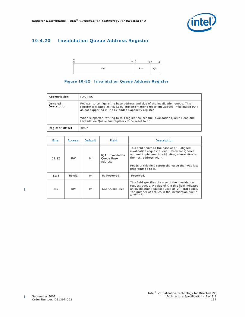
Intel® Virtualization Technology for Directed I/OSeptember 2007 Architecture Specification - Rev 1.1Order Number: D51397-003 137
Register Descriptions—Intel® Virtualization Technology for Directed I/O
10.4.23 Invalidation Queue Address Register
Figure 10-52. Invalidation Queue Address Register
Abbreviation IQA_REG
General Description
Register to configure the base address and size of the invalidation queue. This register is treated as RsvdZ by implementations reporting Queued Invalidation (QI) as not supported in the Extended Capability register.
When supported, writing to this register causes the Invalidation Queue Head and Invalidation Queue Tail registers to be reset to 0h.
Register Offset 090h
Bits Access Default Field Description
63:12 RW 0hIQA: Invalidation Queue Base Address
This field points to the base of 4KB aligned invalidation request queue. Hardware ignores and not implement bits 63:HAW, where HAW is the host address width.
Reads of this field return the value that was last programmed to it.
11:3 RsvdZ 0h R: Reserved Reserved.
2:0 RW 0h QS: Queue Size
This field specifies the size of the invalidation request queue. A value of X in this field indicates an invalidation request queue of (2X) 4KB pages. The number of entries in the invalidation queue is 2(X + 8).
0
IQA Rsvd
63
12 2
QS
311

Intel® Virtualization Technology for Directed I/O—Register Descriptions
Intel® Virtualization Technology for Directed I/OArchitecture Specification - Rev 1.1 September 2007138 Order Number: D51397-003
10.4.24 Invalidation Completion Status Register
Figure 10-53. Invalidation Completion Status Register
Abbreviation ICS_REG
General Description
Register to report completion status of invalidation wait descriptor with Interrupt Flag (IF) Set. This register is treated as RsvdZ by implementations reporting Queued Invalidation (QI) as not supported in the Extended Capability register.
Register Offset 09Ch
Bits Access Default Field Description
31:1 RsvdZ 0h R: Reserved Reserved.
0 RW1CS 0IWC: Invalidation Wait Descriptor Complete
Indicates completion of Invalidation Wait Descriptor with Interrupt Flag (IF) field Set. Hardware implementations not supporting queued invalidations implement this field as RsvdZ.
IWC
0
Rsvd
31 1

Intel® Virtualization Technology for Directed I/OSeptember 2007 Architecture Specification - Rev 1.1Order Number: D51397-003 139
Register Descriptions—Intel® Virtualization Technology for Directed I/O
10.4.25 Invalidation Event Control Register
Figure 10-54. Invalidation Event Control Register
Abbreviation IECTL_REG
General Description
Register specifying the invalidation event interrupt control bits. This register is treated as RsvdZ by implementations reporting Queued Invalidation (QI) as not supported in the Extended Capability register.
Register Offset 0A0h
Bits Access Default Field Description
31 RW 1 IM: Interrupt Mask
• 0: No masking of interrupt. When a invalidation event condition is detected, hardware issues an interrupt message (using the Invalidation Event Data & Invalidation Event Address register values).
• 1: This is the value on reset. Software may mask interrupt message generation by setting this field. Hardware is prohibited from sending the interrupt message when this field is Set.
30 RO 0 IP: Interrupt Pending
Hardware sets the IP field whenever it detects an interrupt condition. Interrupt condition is defined as:• An Invalidation Wait Descriptor with
Interrupt Flag (IF) field Set completed, setting the IWC field in the Invalidation Completion Status register.
• If the IWC field in the Invalidation Completion Status register was already Set at the time of setting this field, it is not treated as a new interrupt condition.
The IP field is kept Set by hardware while the interrupt message is held pending. The interrupt message could be held pending due to interrupt mask (IM field) being Set, or due to other transient hardware conditions. The IP field is cleared by hardware as soon as the interrupt message pending condition is serviced. This could be due to either:• Hardware issuing the interrupt message due
to either change in the transient hardware condition that caused interrupt message to be held pending or due to software clearing the IM field.
• Software servicing the IWC field in the Invalidation Completion Status register.
29:0 RsvdP Xh R: Reserved Reserved.
IM
0
IP Rsvd
31
30
29
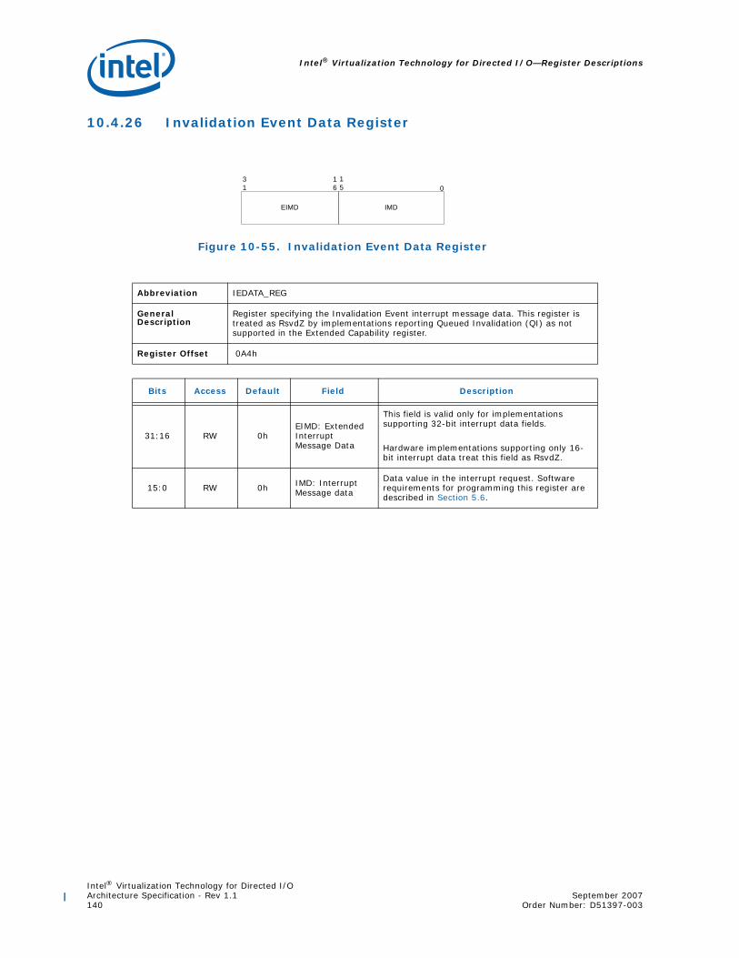
Intel® Virtualization Technology for Directed I/O—Register Descriptions
Intel® Virtualization Technology for Directed I/OArchitecture Specification - Rev 1.1 September 2007140 Order Number: D51397-003
10.4.26 Invalidation Event Data Register
Figure 10-55. Invalidation Event Data Register
Abbreviation IEDATA_REG
General Description
Register specifying the Invalidation Event interrupt message data. This register is treated as RsvdZ by implementations reporting Queued Invalidation (QI) as not supported in the Extended Capability register.
Register Offset 0A4h
Bits Access Default Field Description
31:16 RW 0hEIMD: Extended Interrupt Message Data
This field is valid only for implementations supporting 32-bit interrupt data fields.
Hardware implementations supporting only 16-bit interrupt data treat this field as RsvdZ.
15:0 RW 0h IMD: Interrupt Message data
Data value in the interrupt request. Software requirements for programming this register are described in Section 5.6.
EIMD
0
IMD
31
16
15

Intel® Virtualization Technology for Directed I/OSeptember 2007 Architecture Specification - Rev 1.1Order Number: D51397-003 141
Register Descriptions—Intel® Virtualization Technology for Directed I/O
10.4.27 Invalidation Event Address Register
Figure 10-56. Invalidation Event Address Register
Abbreviation IEADDR_REG
General Description
Register specifying the Invalidation Event Interrupt message address.This register is treated as RsvdZ by implementations reporting Queued Invalidation (QI) as not supported in the Extended Capability register.
Register Offset 0A8h
Bits Access Default Field Description
31:2 RW 0h MA: Message address
When fault events are enabled, the contents of this register specify the DWORD-aligned address (bits 31:2) for the interrupt request.
Software requirements for programming this register are described in Section 5.6.
1:0 RsvdZ 0h R: Reserved Reserved.
0
RsvdMA
31 12

Intel® Virtualization Technology for Directed I/O—Register Descriptions
Intel® Virtualization Technology for Directed I/OArchitecture Specification - Rev 1.1 September 2007142 Order Number: D51397-003
10.4.28 Invalidation Event Upper Address Register
Figure 10-57. Invalidation Event Upper Address Register
Abbreviation IEUADDR_REG
General Description Register specifying the Invalidation Event interrupt message upper address.
Register Offset 0ACh
Bits Access Default Field Description
31:0 RW 0h MUA: Message upper address
Hardware implementations supporting Queued Invalidations and Extended Interrupt Mode are required to implement this register.
Software requirements for programming this register are described in Section 5.6.
Hardware implementations not supporting Queued Invalidations or Extended Interrupt Mode may treat this field as RsvdZ.
0
MUA
31
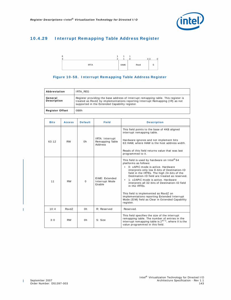
Intel® Virtualization Technology for Directed I/OSeptember 2007 Architecture Specification - Rev 1.1Order Number: D51397-003 143
Register Descriptions—Intel® Virtualization Technology for Directed I/O
10.4.29 Interrupt Remapping Table Address Register
Figure 10-58. Interrupt Remapping Table Address Register
Abbreviation IRTA_REG
General Description
Register providing the base address of Interrupt remapping table. This register is treated as RsvdZ by implementations reporting Interrupt Remapping (IR) as not supported in the Extended Capability register.
Register Offset 0B8h
Bits Access Default Field Description
63:12 RW 0hIRTA: Interrupt Remapping Table Address
This field points to the base of 4KB aligned interrupt remapping table.
Hardware ignores and not implement bits 63:HAW, where HAW is the host address width. Reads of this field returns value that was last programmed to it.
11 RW 0EIME: Extended Interrupt Mode Enable
This field is used by hardware on Intel®64 platforms as follows:• 0: xAPIC mode is active. Hardware
interprets only low 8-bits of Destination-ID field in the IRTEs. The high 24-bits of the Destination-ID field are treated as reserved.
• 1: x2APIC mode is active. Hardware interprets all 32-bits of Destination-ID field in the IRTEs.
This field is implemented as RsvdZ on implementations reporting Extended Interrupt Mode (EIM) field as Clear in Extended Capability register.
10:4 RsvdZ 0h R: Reserved Reserved.
3:0 RW 0h S: Size
This field specifies the size of the interrupt remapping table. The number of entries in the interrupt remapping table is 2X+1, where X is the value programmed in this field.
0
IRTA Rsvd
63
12 3
S
411
EIME
10

Intel® Virtualization Technology for Directed I/O—Programming Considerations
Intel® Virtualization Technology for Directed I/OArchitecture Specification - Rev 1.1 September 2007144 Order Number: D51397-003
11 Programming Considerations
This section summarizes the remapping hardware programming requirements.
11.1 Write Buffer Flushing
For hardware implementations requiring write buffer flushing (RWBF=1 in the Capability register), software updates to memory-resident remapping structures may be held in Root-Complex internal hardware write-buffers, and not implicitly visible to remapping hardware. For such implementations, software must explicitly make these updates visible to hardware through one of two methods below:
• For updates to remapping hardware structures that require context-cache, IOTLB or IEC invalidation operations to flush stale entries from the hardware caches, no additional action is required to make the modifications visible to hardware. This is because, hardware performs an implicit write-buffer-flushing as a pre-condition to context-cache, IOTLB and IEC invalidation operations.
• For updates to remapping hardware structures (such as modifying a currently not-present entry) that do not require context-cache, IOTLB or IEC invalidations, software must explicitly perform write-buffer-flushing to ensure the updated structures are visible to hardware.
11.2 Set Root Table Pointer Operation
Software must always perform a set root table pointer operation before enabling or re-enabling (after disabling) DMA-remapping hardware.
On a root table pointer set operation, software must globally invalidate the context-cache, and after its completion globally invalidate the IOTLB to ensure hardware references only the new structures for further remapping.
If software sets the root table pointer while DMA-remapping hardware is active, software must ensure the structures referenced by the new root table pointer provide identical remapping results as the structures referenced by the previous root table pointer to ensure any valid in-flight DMA requests are properly remapped. This is required since hardware may utilize the old structures or the new structures to remap in-flight DMA requests, until the context-cache and IOTLB invalidations are completed.
11.3 Context-Entry Programming
Software must ensure that, for a given DMA-remapping hardware unit, context-entries programmed with the same domain-id (DID) must be programmed with the same value for the Address Space Root (ASR) field. This is required since hardware implementations are allowed to tag the various DMA-remapping caches with DID. Context entries with the same value in the ASR field are recommended to use the same DID value for best hardware efficiency

Intel® Virtualization Technology for Directed I/OSeptember 2007 Architecture Specification - Rev 1.1Order Number: D51397-003 145
Programming Considerations—Intel® Virtualization Technology for Directed I/O
11.4 Modifying Root and Context Entries
When DMA-remapping hardware is active:
• Software must serially invalidate the context-cache and the IOTLB when updating root-entries or context-entries. The serialization is required since hardware may utilize information from the context-caches to tag new entries inserted to the IOTLB while processing in-flight DMA requests.
• Software must not modify fields other than the Present (P) field of currently present root-entries or context-entries. If modifications to other fields are required, software must first make these entries not-present (P=0), which requires serial invalidation of context-cache and IOTLB, and then transition them to present (P=1) state along with the modifications.
11.5 Caching Mode Considerations
For implementations reporting Caching Mode (CM) as Clear in the Capability register:
• Software is not required to perform context-cache and IOTLB invalidations for modifications to not-present or erroneous root or context-entries for them to be effective.
• Software is not required to perform IOTLB invalidations for modifications to any individual not-present (R and W fields Clear) or erroneous page-directory or page-table entries for them to be effective. Any modifications that result in decreasing the effective permissions (read-write to not-present, read-only to write-only, write-only to read-only, read-only to not-present, write-only to not-present, read-write to read-only, read-write to write only) or partial permission increases (read-only to read-write, write-only to read-write) require software to invalidate the IOTLB for them to be effective.
For implementations reporting Caching Mode (CM) as Set in the Capability register:
• Software is required to invalidate the context-cache for any/all modifications to root or context entries for them to be effective.
• Software is required to invalidate the IOTLB (after the context-cache invalidation completion) for any modifications to present root or context entries for them to be effective.
• Software is required to invalidate the IOTLB for any/all modifications to any active page directory/table entries for them to be effective.
• Software must not use domain-id value of zero as it is reserved on implementations reporting Caching Mode (CM) as Set.
11.6 Serialization Requirements
A register used to submit a command to a remapping unit is owned by hardware while the command is pending in hardware. Software must not update the associated register until hardware indicates the command processing is complete through appropriate status registers.
For each remapping hardware unit, software must serialize commands submitted through the Global Command register, Context Command register, IOTLB registers and Protected Memory Enable register.
For platforms supporting more than one remapping hardware unit, there are no hardware serialization requirements for operations across remapping hardware units.
11.7 Invalidation Considerations
For page-table updates that do not modify PDEs (or if Caching Mode (CM) is Clear, modify only not-present PDEs), software may specify the Invalidation Hint (IH = 1) on page-selective IOTLB invalidations. Hardware may preserve the non-leaf (page-directory) caches on invalidation requests specifying IH=1. Preserving non-leaf caches may improve performance by avoiding the full-length page-walks for in-flight DMA requests.

Intel® Virtualization Technology for Directed I/O—Programming Considerations
Intel® Virtualization Technology for Directed I/OArchitecture Specification - Rev 1.1 September 2007146 Order Number: D51397-003
11.8 Sharing Remapping Structures Across Hardware Units
Software may share (fully or partially) the various remapping structures across multiple hardware units. When the remapping structures are shared across hardware units, software must explicitly perform the invalidation operations on each remapping hardware unit sharing the modified entries. The software requirements described in this section must be individually applied for each such invalidation operation.
11.9 Set Interrupt Remapping Table Pointer Operation
Software must always set the interrupt-remapping table pointer before enabling or re-enabling (after disabling) interrupt-remapping hardware.
Software must always follow the interrupt-remapping table pointer set operation with a global invalidate of the IEC to ensure hardware references the new structures before enabling interrupt remapping.
If software updates the interrupt-remapping table pointer while interrupt-remap hardware is active, software must ensure the structures referenced by the new interrupt-remapping table pointer provide identical remapping results as the structures referenced by the previous interrupt-remapping table pointer to ensure any valid in-flight interrupt requests are properly remapped. This is required since hardware may utilize the old structures or the new structures to remap in-flight interrupt requests, until the IEC invalidation is completed.

Intel® Virtualization Technology for Directed I/OSeptember 2007 Architecture Specification - Rev 1.1Order Number: D51397-003 147
Fault Reason Encodings—Intel® Virtualization Technology for Directed I/O
Appendix A Fault Reason Encodings
The following table describes the meaning of the codes assigned to various faults.
Encoding Fault Reason Description
0h Reserved. Used by software when initializing fault records (for advanced fault logging)
DMA Remapping Fault Conditions
1h The present (P) field in the root-entry used to process the DMA request is Clear.
2h The present (P) field in the context-entry used to process the DMA request is Clear.
3h
Hardware detected invalid programming of a context-entry. For example:• The address width (AW) field programmed with a value not supported by the
hardware implementation.• The translation-type (T) field programmed to indicate a translation type not
supported by the hardware implementation.• Hardware attempt to access the page table base through the Address Space Root
(ASR) field of the context-entry resulted in error.
4h
The DMA request attempted to access an address beyond (2X - 1), where X is the minimum of the maximum guest address width (MGAW) reported through the Capability register and the value in the address-width (AW) field of the context-entry used to process the DMA request.
5h The Write (W) field in a page-table entry used for address translation of the DMA write request is Clear.
6h
The Read (R) field in a page-table entry used for address translation of the DMA read request is Clear. For implementations reporting ZLR field as set in the Capability register, this fault condition is not applicable for zero-length DMA read requests to write-only pages.
7h Hardware attempt to access the next level page table through the Address (ADDR) field of the page-table entry resulted in error.
8h Hardware attempt to access the root-entry table through the root-table address (RTA) field in the Root-entry Table Address register resulted in error.
9h Hardware attempt to access context-entry table through context-entry table pointer (CTP) field resulted in error.
Ah Hardware detected reserved field(s) that are not initialized to zero in a root-entry with present (P) field Set.
Bh Hardware detected reserved field(s) that are not initialized to zero in a context-entry with present (P) field Set.
Ch Hardware detected reserved field(s) that are not initialized to zero in a page-table entry with at least one of read (R) and write (W) field Set.
Dh Translation request or translated DMA explicitly blocked due to the programming of the Translation Type (T) field in the corresponding present context-entry.

Intel® Virtualization Technology for Directed I/O—Fault Reason Encodings
Intel® Virtualization Technology for Directed I/OArchitecture Specification - Rev 1.1 September 2007148 Order Number: D51397-003
Interrupt Remapping Fault Conditions
20h Decoding of the interrupt request per the Remappable request format detected one or more reserved fields as Set.
21h The interrupt_index value computed for the interrupt request is greater than the maximum allowed for the interrupt Remapping table-size configured by software.
22h The present (P) field in the IRTE entry corresponding to the interrupt_index of the interrupt request is Clear.
23h Hardware attempt to access the interrupt Remapping table through the interrupt remapping table address (IRTA) field in the IRTA_REG register resulted in error.
24hHardware detected one ore more reserved field(s) that are not initialized to zero in an IRTE. This includes the case where software programmed various conditional reserved fields wrongly.
25h
On Intel®64 platforms, hardware blocked an interrupt request in Compatibility format either due to extended interrupt mode enabled (EIME field Set in Interrupt Remapping Table Address register) or Compatibility format interrupts disabled (CFIS field Clear in Global Status register).On ItaniumTM platforms, hardware blocked an interrupt request in Compatibility format.
26hHardware blocked a Remappable interrupt request due to verification failure of the interrupt requester’s source-id per the programming of SID, SVT and SQ fields in the corresponding IRTE.
Eh - 1Fh Reserved.
27h - FFh Reserved.
Encoding Fault Reason Description