Embed Size (px)
Citation preview
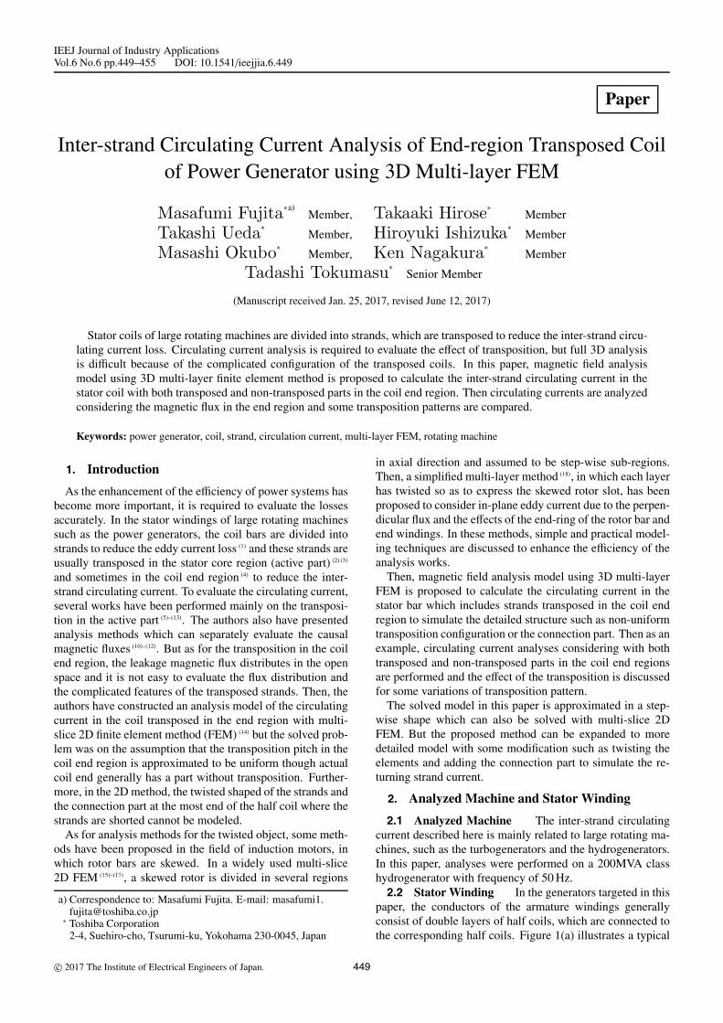
IEEJ Journal of Industry ApplicationsVol.6 No.6 pp.449–455 DOI: 10.1541/ieejjia.6.449
Paper
Inter-strand Circulating Current Analysis of End-region Transposed Coilof Power Generator using 3D Multi-layer FEM
Masafumi Fujita∗a)Member, Takaaki Hirose∗ Member
Takashi Ueda∗ Member, Hiroyuki Ishizuka∗ Member
Masashi Okubo∗ Member, Ken Nagakura∗ Member
Tadashi Tokumasu∗ Senior Member
(Manuscript received Jan. 25, 2017, revised June 12, 2017)
Stator coils of large rotating machines are divided into strands, which are transposed to reduce the inter-strand circu-lating current loss. Circulating current analysis is required to evaluate the effect of transposition, but full 3D analysisis difficult because of the complicated configuration of the transposed coils. In this paper, magnetic field analysismodel using 3D multi-layer finite element method is proposed to calculate the inter-strand circulating current in thestator coil with both transposed and non-transposed parts in the coil end region. Then circulating currents are analyzedconsidering the magnetic flux in the end region and some transposition patterns are compared.
Keywords: power generator, coil, strand, circulation current, multi-layer FEM, rotating machine
1. Introduction
As the enhancement of the efficiency of power systems hasbecome more important, it is required to evaluate the lossesaccurately. In the stator windings of large rotating machinessuch as the power generators, the coil bars are divided intostrands to reduce the eddy current loss (1) and these strands areusually transposed in the stator core region (active part) (2) (3)
and sometimes in the coil end region (4) to reduce the inter-strand circulating current. To evaluate the circulating current,several works have been performed mainly on the transposi-tion in the active part (5)–(13). The authors also have presentedanalysis methods which can separately evaluate the causalmagnetic fluxes (10)–(12). But as for the transposition in the coilend region, the leakage magnetic flux distributes in the openspace and it is not easy to evaluate the flux distribution andthe complicated features of the transposed strands. Then, theauthors have constructed an analysis model of the circulatingcurrent in the coil transposed in the end region with multi-slice 2D finite element method (FEM) (14) but the solved prob-lem was on the assumption that the transposition pitch in thecoil end region is approximated to be uniform though actualcoil end generally has a part without transposition. Further-more, in the 2D method, the twisted shaped of the strands andthe connection part at the most end of the half coil where thestrands are shorted cannot be modeled.
As for analysis methods for the twisted object, some meth-ods have been proposed in the field of induction motors, inwhich rotor bars are skewed. In a widely used multi-slice2D FEM (15)–(17), a skewed rotor is divided in several regions
a) Correspondence to: Masafumi Fujita. E-mail: [email protected]∗ Toshiba Corporation
2-4, Suehiro-cho, Tsurumi-ku, Yokohama 230-0045, Japan
in axial direction and assumed to be step-wise sub-regions.Then, a simplified multi-layer method (18), in which each layerhas twisted so as to express the skewed rotor slot, has beenproposed to consider in-plane eddy current due to the perpen-dicular flux and the effects of the end-ring of the rotor bar andend windings. In these methods, simple and practical model-ing techniques are discussed to enhance the efficiency of theanalysis works.
Then, magnetic field analysis model using 3D multi-layerFEM is proposed to calculate the circulating current in thestator bar which includes strands transposed in the coil endregion to simulate the detailed structure such as non-uniformtransposition configuration or the connection part. Then as anexample, circulating current analyses considering with bothtransposed and non-transposed parts in the coil end regionsare performed and the effect of the transposition is discussedfor some variations of transposition pattern.
The solved model in this paper is approximated in a step-wise shape which can also be solved with multi-slice 2DFEM. But the proposed method can be expanded to moredetailed model with some modification such as twisting theelements and adding the connection part to simulate the re-turning strand current.
2. Analyzed Machine and Stator Winding
2.1 Analyzed Machine The inter-strand circulatingcurrent described here is mainly related to large rotating ma-chines, such as the turbogenerators and the hydrogenerators.In this paper, analyses were performed on a 200MVA classhydrogenerator with frequency of 50 Hz.2.2 Stator Winding In the generators targeted in this
paper, the conductors of the armature windings generallyconsist of double layers of half coils, which are connected tothe corresponding half coils. Figure 1(a) illustrates a typical
c© 2017 The Institute of Electrical Engineers of Japan. 449
Circulating Current Analysis using 3D Multi-layer FEM(Masafumi Fujita et al.)
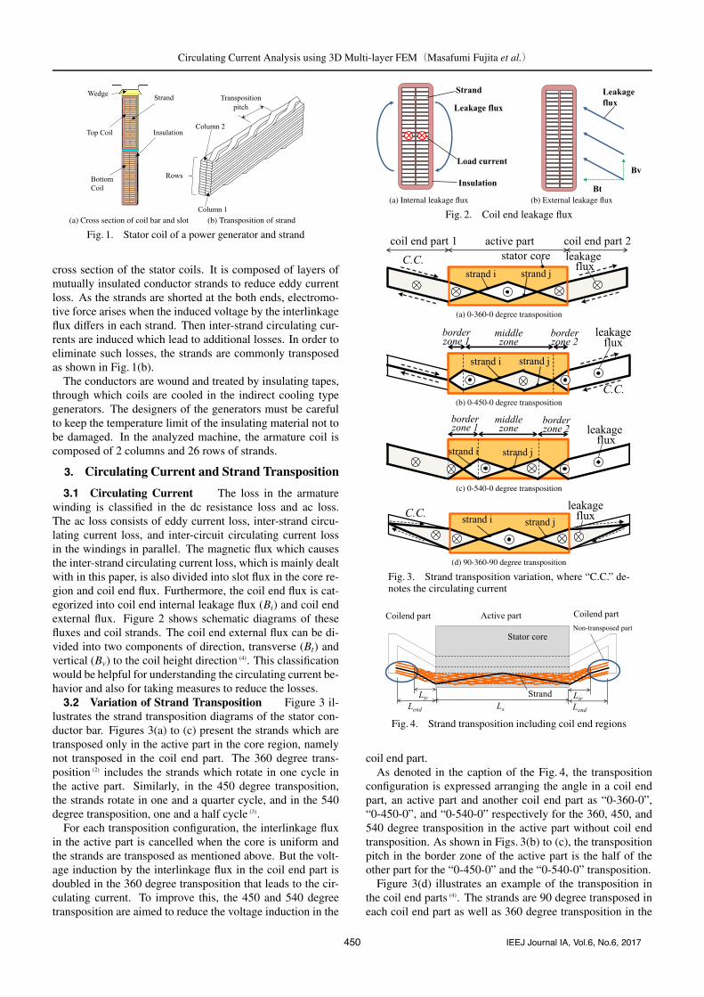
(a) Cross section of coil bar and slot (b) Transposition of strand
Fig. 1. Stator coil of a power generator and strand
cross section of the stator coils. It is composed of layers ofmutually insulated conductor strands to reduce eddy currentloss. As the strands are shorted at the both ends, electromo-tive force arises when the induced voltage by the interlinkageflux differs in each strand. Then inter-strand circulating cur-rents are induced which lead to additional losses. In order toeliminate such losses, the strands are commonly transposedas shown in Fig. 1(b).
The conductors are wound and treated by insulating tapes,through which coils are cooled in the indirect cooling typegenerators. The designers of the generators must be carefulto keep the temperature limit of the insulating material not tobe damaged. In the analyzed machine, the armature coil iscomposed of 2 columns and 26 rows of strands.
3. Circulating Current and Strand Transposition
3.1 Circulating Current The loss in the armaturewinding is classified in the dc resistance loss and ac loss.The ac loss consists of eddy current loss, inter-strand circu-lating current loss, and inter-circuit circulating current lossin the windings in parallel. The magnetic flux which causesthe inter-strand circulating current loss, which is mainly dealtwith in this paper, is also divided into slot flux in the core re-gion and coil end flux. Furthermore, the coil end flux is cat-egorized into coil end internal leakage flux (Bi) and coil endexternal flux. Figure 2 shows schematic diagrams of thesefluxes and coil strands. The coil end external flux can be di-vided into two components of direction, transverse (Bt) andvertical (Bv) to the coil height direction (4). This classificationwould be helpful for understanding the circulating current be-havior and also for taking measures to reduce the losses.3.2 Variation of Strand Transposition Figure 3 il-
lustrates the strand transposition diagrams of the stator con-ductor bar. Figures 3(a) to (c) present the strands which aretransposed only in the active part in the core region, namelynot transposed in the coil end part. The 360 degree trans-position (2) includes the strands which rotate in one cycle inthe active part. Similarly, in the 450 degree transposition,the strands rotate in one and a quarter cycle, and in the 540degree transposition, one and a half cycle (3).
For each transposition configuration, the interlinkage fluxin the active part is cancelled when the core is uniform andthe strands are transposed as mentioned above. But the volt-age induction by the interlinkage flux in the coil end part isdoubled in the 360 degree transposition that leads to the cir-culating current. To improve this, the 450 and 540 degreetransposition are aimed to reduce the voltage induction in the
(a) Internal leakage flux (b) External leakage flux
Fig. 2. Coil end leakage flux
(a) 0-360-0 degree transposition
(b) 0-450-0 degree transposition
(c) 0-540-0 degree transposition
(d) 90-360-90 degree transposition
Fig. 3. Strand transposition variation, where “C.C.” de-notes the circulating current
Fig. 4. Strand transposition including coil end regions
coil end part.As denoted in the caption of the Fig. 4, the transposition
configuration is expressed arranging the angle in a coil endpart, an active part and another coil end part as “0-360-0”,“0-450-0”, and “0-540-0” respectively for the 360, 450, and540 degree transposition in the active part without coil endtransposition. As shown in Figs. 3(b) to (c), the transpositionpitch in the border zone of the active part is the half of theother part for the “0-450-0” and the “0-540-0” transposition.
Figure 3(d) illustrates an example of the transposition inthe coil end parts (4). The strands are 90 degree transposed ineach coil end part as well as 360 degree transposition in the
450 IEEJ Journal IA, Vol.6, No.6, 2017

Circulating Current Analysis using 3D Multi-layer FEM(Masafumi Fujita et al.)
active part so as to reduce the voltage induction. This type oftransposition is expressed as “90-360-90” in this paper.
Figure 4 shows an example of the coil end transposition inthe top coil. In this figure, the strands are transposed partlyin the coil end region and the transposed area is in the sta-tor core side of the coil end. In this paper, the ratio of thetransposed length Ltr to the coil end length Lend is defined as;
Rtr =Ltr
Lend· · · · · · · · · · · · · · · · · · · · · · · · · · · · · · · · · · · · · · (1)
The relation between Rtr and the circulating current loss isstudied in this paper.
4. Analysis Model
4.1 Analysis Model Corresponding to Leakage FluxAs described in the former chapter, the leakage fluxes
which produce circulating currents are classified accordingto their region and their current source. The circulating cur-rent can be analyzed separately due to the inducing leakageflux.
The analysis flow is expressed in Fig. 5. First, in the activepart, as the coils are surrounded by the magnetic material ex-cept at the slot opening, magnetic reluctance to the leakageflux is small and the direction of the leakage flux is mostly re-stricted to a transverse direction. The radial flux could be ne-glected especially for the indirectly cooled generators whoseslot is much deeper than is wide. Therefore, the circulatingcurrent due to the leakage flux in the active part (Ia
c ) is calcu-lated by solving network equations on the strand currents (12).
The circulating current due to the leakage flux in the coilend part (Ii
c, Itc Iv
c ), is calculated separately according to thecategorized components in section 3.1. The external flux (Bt,Bv) is calculated by another coil end magnetic field analysisconsidering the 3D geometry of the coil end region (11).
Then ac analysis is performed using a complex analysis oneach categorized flux (10). The FE analysis model with the coilend region of both sides is analyzed simultaneously with theresistance and the inductance of the strand in the active part.4.2 2D Method (without Coil End Transposition)The 2D analysis model considering the coil end flux with-
out coil end transposition is described in (10) and (11). Thestrands in the coil end region are modeled with 2D meshesand 2 analysis regions represent coil end region 1 and 2 re-spectively as shown in Fig. 6(a). In each region, a constraintcondition is imposed so that the strand current is the same incorresponding strand mesh regions and the flux of all the re-gions is calculated simultaneously (19) (20). The FE mesh aroundthe coil is depicted in Fig. 6(b). In the figure, the strand num-ber is also indicated.
The governing equation is
rot
(1μ
rotA)= − jωσA − σgradφ · · · · · · · · · · · · · · · · (2)
where A is the magnetic vector potential, φ is the electricscalar potential, μ is permeability and σ is conductivity. Inthe 2D problem, A has only z component and can be writtenas Az.
The functional is shown in (3), where Y is the admittancematrix corresponding to the resistance and the inductance of
Fig. 5. Analysis flow
(a) analysis model with 2 mesh regions
(b) mesh around the coil
Fig. 6. FE mesh and strand number
the strand in the active part, β is the element of the cut set ma-trix which corresponds to the connection between the strands,C is variable corresponding to the strand current, n is the rownumber of the strands and the suffix k and l corresponding tothe strand number. L is the longitudinal length of the anal-ysis region and useful to consider the difference of the coilend length of each end (20). Note that some of 2D commercialsoftware cannot deal with the analysis regions whose longi-tudinal lengths are different.
χ =
∫ ⎧⎪⎪⎨⎪⎪⎩(rotAz)
2
2μ+
jωσ2
⎛⎜⎜⎜⎜⎜⎝Az −∑
k
βknCk
L
⎞⎟⎟⎟⎟⎟⎠2⎫⎪⎪⎬⎪⎪⎭ dS L
+ jω∑k,l
YklCkCl · · · · · · · · · · · · · · · · · · · · · · · · · · · (3)
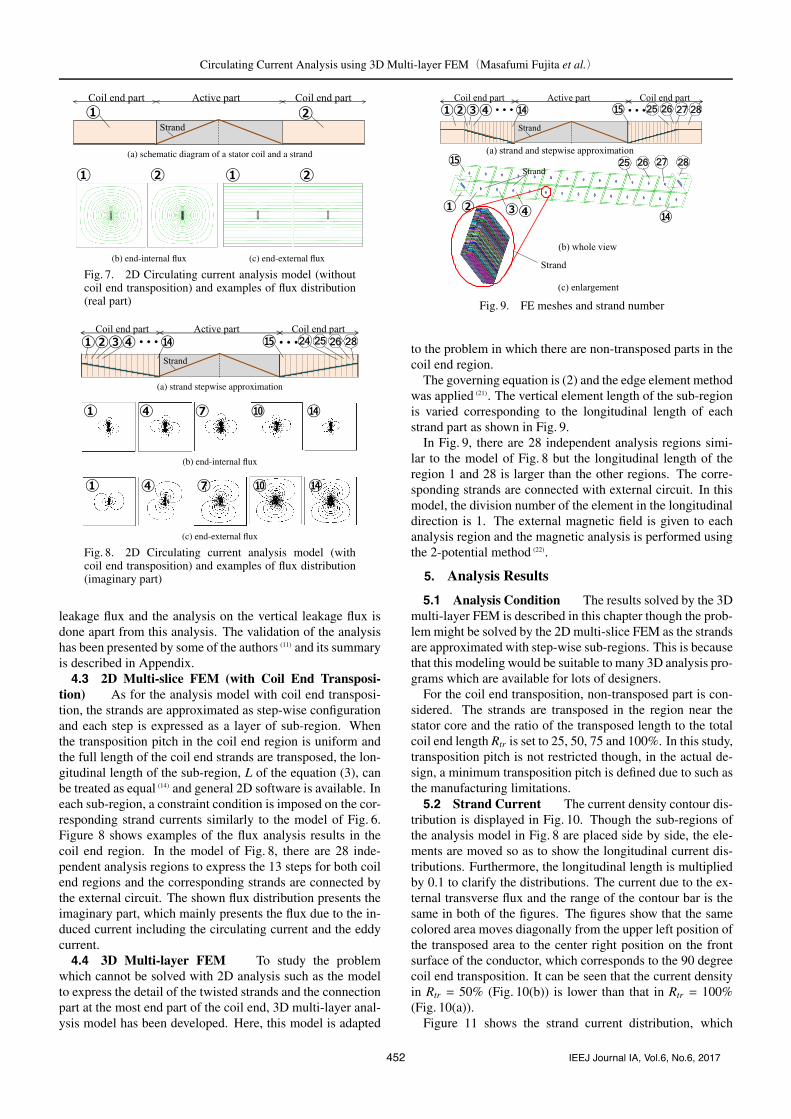
Examples of the flux distribution are shown in Fig. 7. Fig-ures 7(b) and 7(c) include 2 analysis regions. As both fluxdistributions present real part of the complex analysis, whichrepresent the source of magnetic flux. Figure 7(b) illustratesthe internal fluxes which originate in the coil current itself.In this model, the total coil current is given and the analysisis done so as the sum of the strand current becomes the to-tal current. Figure 7(c) denotes the end-external fluxes whichoriginate in the flux by the other coils, the rotor coil and themagnetic structures. This analysis deals with the transverse
451 IEEJ Journal IA, Vol.6, No.6, 2017
Circulating Current Analysis using 3D Multi-layer FEM(Masafumi Fujita et al.)
(a) schematic diagram of a stator coil and a strand
(b) end-internal flux (c) end-external flux
Fig. 7. 2D Circulating current analysis model (withoutcoil end transposition) and examples of flux distribution(real part)
(a) strand stepwise approximation
(b) end-internal flux
(c) end-external flux
Fig. 8. 2D Circulating current analysis model (withcoil end transposition) and examples of flux distribution(imaginary part)
leakage flux and the analysis on the vertical leakage flux isdone apart from this analysis. The validation of the analysishas been presented by some of the authors (11) and its summaryis described in Appendix.4.3 2D Multi-slice FEM (with Coil End Transposi-
tion) As for the analysis model with coil end transposi-tion, the strands are approximated as step-wise configurationand each step is expressed as a layer of sub-region. Whenthe transposition pitch in the coil end region is uniform andthe full length of the coil end strands are transposed, the lon-gitudinal length of the sub-region, L of the equation (3), canbe treated as equal (14) and general 2D software is available. Ineach sub-region, a constraint condition is imposed on the cor-responding strand currents similarly to the model of Fig. 6.Figure 8 shows examples of the flux analysis results in thecoil end region. In the model of Fig. 8, there are 28 inde-pendent analysis regions to express the 13 steps for both coilend regions and the corresponding strands are connected bythe external circuit. The shown flux distribution presents theimaginary part, which mainly presents the flux due to the in-duced current including the circulating current and the eddycurrent.4.4 3D Multi-layer FEM To study the problem
which cannot be solved with 2D analysis such as the modelto express the detail of the twisted strands and the connectionpart at the most end part of the coil end, 3D multi-layer anal-ysis model has been developed. Here, this model is adapted
Fig. 9. FE meshes and strand number
to the problem in which there are non-transposed parts in thecoil end region.
The governing equation is (2) and the edge element methodwas applied (21). The vertical element length of the sub-regionis varied corresponding to the longitudinal length of eachstrand part as shown in Fig. 9.
In Fig. 9, there are 28 independent analysis regions simi-lar to the model of Fig. 8 but the longitudinal length of theregion 1 and 28 is larger than the other regions. The corre-sponding strands are connected with external circuit. In thismodel, the division number of the element in the longitudinaldirection is 1. The external magnetic field is given to eachanalysis region and the magnetic analysis is performed usingthe 2-potential method (22).
5. Analysis Results
5.1 Analysis Condition The results solved by the 3Dmulti-layer FEM is described in this chapter though the prob-lem might be solved by the 2D multi-slice FEM as the strandsare approximated with step-wise sub-regions. This is becausethat this modeling would be suitable to many 3D analysis pro-grams which are available for lots of designers.
For the coil end transposition, non-transposed part is con-sidered. The strands are transposed in the region near thestator core and the ratio of the transposed length to the totalcoil end length Rtr is set to 25, 50, 75 and 100%. In this study,transposition pitch is not restricted though, in the actual de-sign, a minimum transposition pitch is defined due to such asthe manufacturing limitations.5.2 Strand Current The current density contour dis-
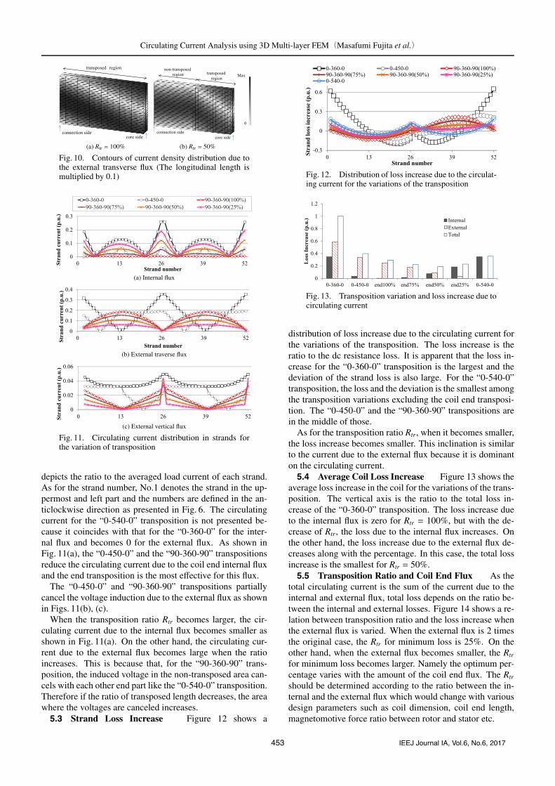
tribution is displayed in Fig. 10. Though the sub-regions ofthe analysis model in Fig. 8 are placed side by side, the ele-ments are moved so as to show the longitudinal current dis-tributions. Furthermore, the longitudinal length is multipliedby 0.1 to clarify the distributions. The current due to the ex-ternal transverse flux and the range of the contour bar is thesame in both of the figures. The figures show that the samecolored area moves diagonally from the upper left position ofthe transposed area to the center right position on the frontsurface of the conductor, which corresponds to the 90 degreecoil end transposition. It can be seen that the current densityin Rtr = 50% (Fig. 10(b)) is lower than that in Rtr = 100%(Fig. 10(a)).
Figure 11 shows the strand current distribution, which
452 IEEJ Journal IA, Vol.6, No.6, 2017
Circulating Current Analysis using 3D Multi-layer FEM(Masafumi Fujita et al.)
(a) Rtr = 100% (b) Rtr = 50%
Fig. 10. Contours of current density distribution due tothe external transverse flux (The longitudinal length ismultiplied by 0.1)
(a) Internal flux
(b) External traverse flux
(c) External vertical flux
Fig. 11. Circulating current distribution in strands forthe variation of transposition
depicts the ratio to the averaged load current of each strand.As for the strand number, No.1 denotes the strand in the up-permost and left part and the numbers are defined in the an-ticlockwise direction as presented in Fig. 6. The circulatingcurrent for the “0-540-0” transposition is not presented be-cause it coincides with that for the “0-360-0” for the inter-nal flux and becomes 0 for the external flux. As shown inFig. 11(a), the “0-450-0” and the “90-360-90” transpositionsreduce the circulating current due to the coil end internal fluxand the end transposition is the most effective for this flux.
The “0-450-0” and “90-360-90” transpositions partiallycancel the voltage induction due to the external flux as shownin Figs. 11(b), (c).
When the transposition ratio Rtr becomes larger, the cir-culating current due to the internal flux becomes smaller asshown in Fig. 11(a). On the other hand, the circulating cur-rent due to the external flux becomes large when the ratioincreases. This is because that, for the “90-360-90” trans-position, the induced voltage in the non-transposed area can-cels with each other end part like the “0-540-0” transposition.Therefore if the ratio of transposed length decreases, the areawhere the voltages are canceled increases.5.3 Strand Loss Increase Figure 12 shows a
Fig. 12. Distribution of loss increase due to the circulat-ing current for the variations of the transposition
Fig. 13. Transposition variation and loss increase due tocirculating current
distribution of loss increase due to the circulating current forthe variations of the transposition. The loss increase is theratio to the dc resistance loss. It is apparent that the loss in-crease for the “0-360-0” transposition is the largest and thedeviation of the strand loss is also large. For the “0-540-0”transposition, the loss and the deviation is the smallest amongthe transposition variations excluding the coil end transposi-tion. The “0-450-0” and the “90-360-90” transpositions arein the middle of those.
As for the transposition ratio Rtr, when it becomes smaller,the loss increase becomes smaller. This inclination is similarto the current due to the external flux because it is dominanton the circulating current.5.4 Average Coil Loss Increase Figure 13 shows the
average loss increase in the coil for the variations of the trans-position. The vertical axis is the ratio to the total loss in-crease of the “0-360-0” transposition. The loss increase dueto the internal flux is zero for Rtr = 100%, but with the de-crease of Rtr, the loss due to the internal flux increases. Onthe other hand, the loss increase due to the external flux de-creases along with the percentage. In this case, the total lossincrease is the smallest for Rtr = 50%.5.5 Transposition Ratio and Coil End Flux As the
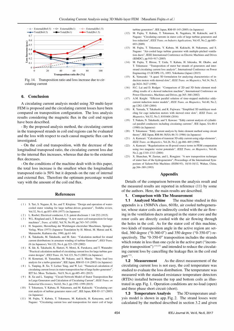
total circulating current is the sum of the current due to theinternal and external flux, total loss depends on the ratio be-tween the internal and external losses. Figure 14 shows a re-lation between transposition ratio and the loss increase whenthe external flux is varied. When the external flux is 2 timesthe original case, the Rtr for minimum loss is 25%. On theother hand, when the external flux becomes smaller, the Rtr
for minimum loss becomes larger. Namely the optimum per-centage varies with the amount of the coil end flux. The Rtr
should be determined according to the ratio between the in-ternal and the external flux which would change with variousdesign parameters such as coil dimension, coil end length,magnetomotive force ratio between rotor and stator etc.
453 IEEJ Journal IA, Vol.6, No.6, 2017
Circulating Current Analysis using 3D Multi-layer FEM(Masafumi Fujita et al.)
Fig. 14. Transposition ratio and loss increase due to cir-culating current
6. Conclusion
A circulating current analysis model using 3D multi-layerFEM is proposed and the circulating current losses have beencompared on transposition configuration. The loss analysisresults considering the magnetic flux in the coil end regionhave been described.
- By the proposed analysis method, the circulating currentin the transposed strands in coil end regions can be evaluatedand the loss with respect to each causal magnetic flux can beinvestigated.
- On the coil end transposition, with the decrease of thelongitudinal transposed ratio, the circulating current loss dueto the internal flux increases, whereas that due to the externalflux decreases.
- On the conditions of the machine dealt with in this paper,the total loss increase is the smallest when the longitudinaltransposed ratio is 50% but it depends on the rate of internaland external flux. Therefore the optimum percentage wouldvary with the amount of the coil end flux.
References
( 1 ) S. Tari, S. Nagano, K. Ito, and T. Kitajima: “Design and operation of water-cooled stator winding for large turbine-driven generator”, Toshiba review,Vol.32, No.4, pp.853–858 (1977) (in Japanese)
( 2 ) L. Roebel, Electrical conductor, U.S. patent disclosure 1 144 252 (1915)( 3 ) W.L. Ringland and L.T. Rosenberg: “A new stator coil transposition for large
machines”, Trans. of AIEE, Vol.78, No.99, pp.743–747 (1959)( 4 ) H. Sequentz, Herstellung der Wicklungen electrisher Maschinen, Springer-
Verlag, Wien (1973) (Japanese Translation by H. Mitsui, M. Matsui and K.Matsunobe, Kaihatsu-sha, 1990, pp.61–64)
( 5 ) K. Takahashi, M. Takahashi, and M. Sato: “Calculation method for strandcurrent distributions in armature winding of turbine Generator”, IEEJ Trans.IA (in Japanese), Vol.122, No.4, pp.323–329 (2002)
( 6 ) K. Ide, K. Takahashi, K. Hattori, N. Motoi, K. Furukawa, and T. Watanabe:“Practical calculation method of circulating current loss for large turbine gen-erator designs”, IEEJ Trans. IA, Vol.123, No.5 (2003) (in Japanese)
( 7 ) H. Kometani, H. Yamashita, M. Nakano, and S. Maeda: “Stray load lossanalysis for a turbo-generator”, IEE Japan, RM-03-114 (2003) (in Japanese)
( 8 ) L. Yanping, B. Xu, Y. Lichao Yang, and W. Lei: “Numerical calculation ofcirculating current losses in stator transposition bar of large hydro-generator”,IET Sci. Meas. Technolo., Vol.9, No.4, pp.485–491 (2015)
( 9 ) B. Xu and L. Yanping: “Circuit Network Model of Stator Transposition Barin Large Generators and Calculation of Circulating Current”, IEEE Trans. onIndustrial Electronics, Vol.62, No.3, pp.1392–1399 (2015)
(10) T. Tokumasu, Y. Kabata, H. Nakamura, and M. Kakiuchi: “Circulating cur-rent analysis of turbine generator stator coil”, IEE Japan, RM-03-117 (2003)(in Japanese)
(11) M. Fujita, Y. Kabata, T. Tokumasu, M. Kakiuchi, H. Katayama, and S.Nagano: “Circulating current loss and transposition for stator coil of large
turbine generators”, IEE Japan, RM-05-145 (2005) (in Japanese)(12) M. Fujita, Y. Kabata, T. Tokumasu, K. Nagakura, M. Kakiuchi, and S.
Nagano: “Circulating currents in stator coils of large turbine generators andloss reduction”, IEEE Trans. on Industry Applications, Vol.45, No.2, pp.685–693 (2009)
(13) M. Fujita, T. Tokumasu, Y. Kabata, M. Kakiuchi, H. Nakamura, and S.Nagano: “Air-cooled large turbine generator with multiple-pitched ventila-tion ducts”, IEEE International Conference on Electric Machines and Drives(IEMDC), pp.910–917 (2005)
(14) M. Fujita, T. Hirose, T. Ueda, Y. Kabata, H. Ishizuka, M. Okubo, andT. Tokumasu: “Transposition of stator bar strands of generators and inter-strand circulating current loss analysis”, International Conference on PowerEngineering-15 (ICOPE-15), 1093, Yokohama (Japan) (2015)
(15) K. Yamazaki: “A quasi 3D formulation for analyzing characteristics of in-duction motors with skewed slots”, IEEE Trans. on Magnetics, Vol.34, No.5,pp.3624–3627 (1998)
(16) H.C. Lai and D. Rodger: “Comparison of 2D and 3D finite element mod-elling results of a skewed induction machine”, International Conference onPower Electronics, Machines and Drives, pp.365–368 (2002)
(17) A.M. Knight: “Efficient parallel solution of time-stepped multislice eddy-current induction motor models”, IEEE Trans. on Magnetics, Vol.40, No.2,pp.1282–1285 (2004)
(18) K. Yamada, Y. Takahashi, and K. Fujiwara: “Simplified 3D multilayer mod-eling for cage induction motors with skewed rotor slots”, IEEE Trans. onMagnetics, Vol.52, No.3, 8101604 (2016)
(19) T. Nakata, N. Takahashi, and Y. Kawase: “Eddy current analysis of cylindri-cal parallel conductors including circulating currents”, IEE Japan, SA-80-4(1980) (in Japanese)
(20) T. Tokumasu: “Eddy current analysis by finite element method using circuittheory”, IEE Japan, RM-86-38/SA-86-31 (1986) (in Japanese)
(21) A. Kameari: “Calculation of transient 3D eddy current using edge-elements”,IEEE Trans. on Magnetics, Vol.26, No.2, pp.466–469 (1990)
(22) A. Kameari: “Regularization on ill-posed source terms in FEM computationusing two magnetic vector potentials”, IEEE Trans. on Magnetics, Vol.40,No.2, pp.1310–1313 (2004)
(23) X. Shanchun, W. Zuotan, and L. Rongjien: “A new transposition techniqueof stator bars of the hydrogenerator”, Proceedings of the International Sym-posium of Salient-Pole Machines (ISSM-93), 10/10-10/12, Wuhan, China,pp.384–389 (1993)
Appendix
Details of the comparison between the analysis result andthe measured results are reported in reference (11) by someof the authors. Here, the main results are described.1. Comparison with The Measurement1.1 Analyzed Machine The machine studied in this
appendix is a 150MVA class, 60 Hz, air cooled turbogenera-tor, whose stator coils are indirectly cooled with the air flow-ing in the ventilation ducts arranged in the stator core and therotor coils are directly cooled with the air flowing throughthe holes in the coil. As for the stator coil of this machine,two kinds of transposition angle in the active region are set-tled, 360 degree (“0-360-0”) and 350 degree (“0-350-0”) re-spectively. The “0-350-0” transposition includes the strandswhich rotate in less than one cycle in the active part (“incom-plete transposition”) (13) (23) and intended to reduce the circulat-ing current loss by cancelling the leakage flux in the coil endpart (12).1.2 Measurement As the direct measurement of the
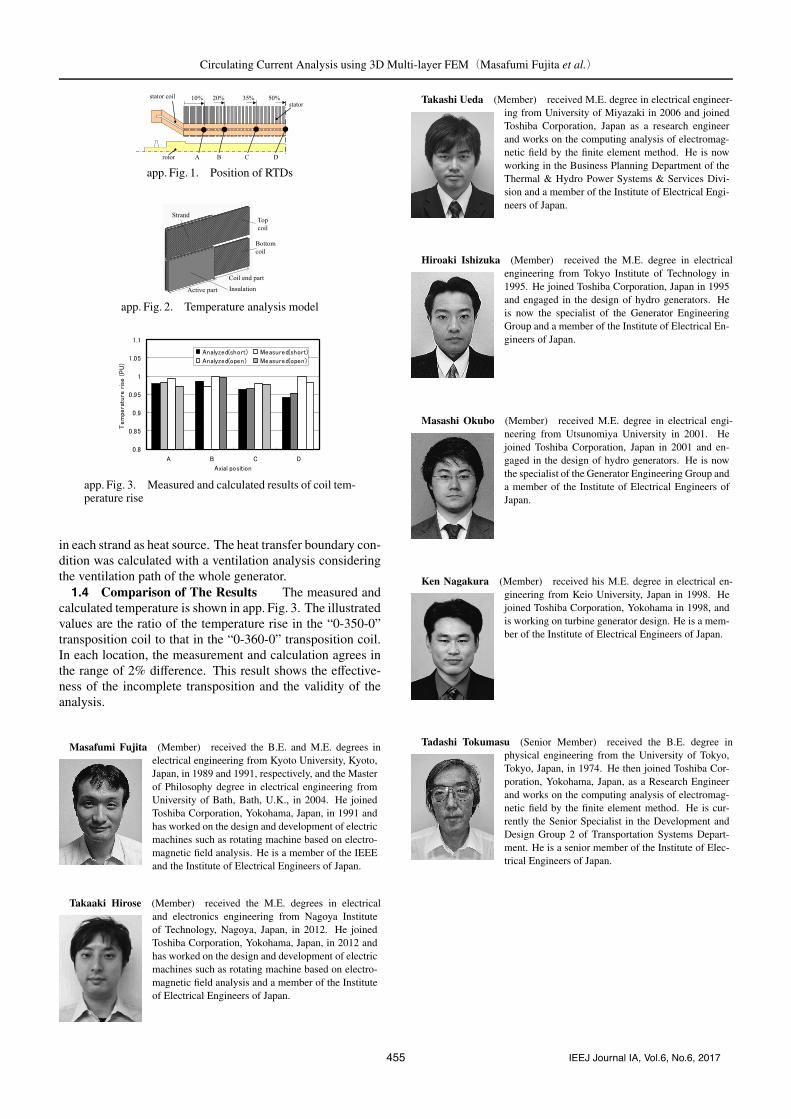
circulating current loss is not easy, the coil temperature wasstudied to evaluate the loss distribution. The temperature wasmeasured with the standard resistance temperature detectors(RTDs) installed between the top and bottom coils as illus-trated in app. Fig. 1. Operation conditions are no-load (open)and three phase short circuit (short).1.3 Temperature Analysis The 3D temperature anal-
ysis model is shown in app. Fig. 2. The strand losses werecalculated by the method described in section 3.2 and given
454 IEEJ Journal IA, Vol.6, No.6, 2017
Circulating Current Analysis using 3D Multi-layer FEM(Masafumi Fujita et al.)
app. Fig. 1. Position of RTDs
app. Fig. 2. Temperature analysis model
app. Fig. 3. Measured and calculated results of coil tem-perature rise
in each strand as heat source. The heat transfer boundary con-dition was calculated with a ventilation analysis consideringthe ventilation path of the whole generator.1.4 Comparison of The Results The measured and
calculated temperature is shown in app. Fig. 3. The illustratedvalues are the ratio of the temperature rise in the “0-350-0”transposition coil to that in the “0-360-0” transposition coil.In each location, the measurement and calculation agrees inthe range of 2% difference. This result shows the effective-ness of the incomplete transposition and the validity of theanalysis.
Masafumi Fujita (Member) received the B.E. and M.E. degrees inelectrical engineering from Kyoto University, Kyoto,Japan, in 1989 and 1991, respectively, and the Masterof Philosophy degree in electrical engineering fromUniversity of Bath, Bath, U.K., in 2004. He joinedToshiba Corporation, Yokohama, Japan, in 1991 andhas worked on the design and development of electricmachines such as rotating machine based on electro-magnetic field analysis. He is a member of the IEEEand the Institute of Electrical Engineers of Japan.
Takaaki Hirose (Member) received the M.E. degrees in electricaland electronics engineering from Nagoya Instituteof Technology, Nagoya, Japan, in 2012. He joinedToshiba Corporation, Yokohama, Japan, in 2012 andhas worked on the design and development of electricmachines such as rotating machine based on electro-magnetic field analysis and a member of the Instituteof Electrical Engineers of Japan.
Takashi Ueda (Member) received M.E. degree in electrical engineer-ing from University of Miyazaki in 2006 and joinedToshiba Corporation, Japan as a research engineerand works on the computing analysis of electromag-netic field by the finite element method. He is nowworking in the Business Planning Department of theThermal & Hydro Power Systems & Services Divi-sion and a member of the Institute of Electrical Engi-neers of Japan.
Hiroaki Ishizuka (Member) received the M.E. degree in electricalengineering from Tokyo Institute of Technology in1995. He joined Toshiba Corporation, Japan in 1995and engaged in the design of hydro generators. Heis now the specialist of the Generator EngineeringGroup and a member of the Institute of Electrical En-gineers of Japan.
Masashi Okubo (Member) received M.E. degree in electrical engi-neering from Utsunomiya University in 2001. Hejoined Toshiba Corporation, Japan in 2001 and en-gaged in the design of hydro generators. He is nowthe specialist of the Generator Engineering Group anda member of the Institute of Electrical Engineers ofJapan.
Ken Nagakura (Member) received his M.E. degree in electrical en-gineering from Keio University, Japan in 1998. Hejoined Toshiba Corporation, Yokohama in 1998, andis working on turbine generator design. He is a mem-ber of the Institute of Electrical Engineers of Japan.
Tadashi Tokumasu (Senior Member) received the B.E. degree inphysical engineering from the University of Tokyo,Tokyo, Japan, in 1974. He then joined Toshiba Cor-poration, Yokohama, Japan, as a Research Engineerand works on the computing analysis of electromag-netic field by the finite element method. He is cur-rently the Senior Specialist in the Development andDesign Group 2 of Transportation Systems Depart-ment. He is a senior member of the Institute of Elec-trical Engineers of Japan.
455 IEEJ Journal IA, Vol.6, No.6, 2017


![Winding Losses Calculation for a 10 MW Ironless stator ... · causing circulating eddy current losses [4]. The current within each strand is the sum of two components [5]: i. input](https://img.pdfslide.net/doc/110x75/5e78bf04acfedb704e6e08e9/winding-losses-calculation-for-a-10-mw-ironless-stator-causing-circulating-eddy.jpg)