Embed Size (px)
Citation preview
MD-111
Prof. Dr. Siegfried SchmauderIMWF, Universität Stuttgart
• Theory
• EAM Potentials
• Frenkel Defects
• Interaction between dislocations and phase boundaries
Molecular Dynamics (Part I)
MD-112
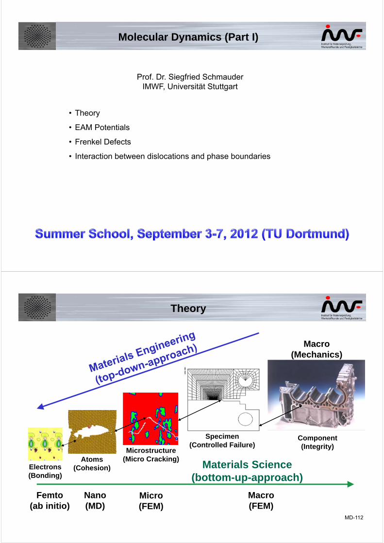
Macro(Mechanics)
Electrons(Bonding)
Atoms(Cohesion)
Microstructure(Micro Cracking)
Specimen(Controlled Failure)
Component(Integrity)
Micro(FEM)
Nano(MD)
Femto(ab initio)
Macro(FEM)
Materials Science(bottom-up-approach)
Theory
MD-113
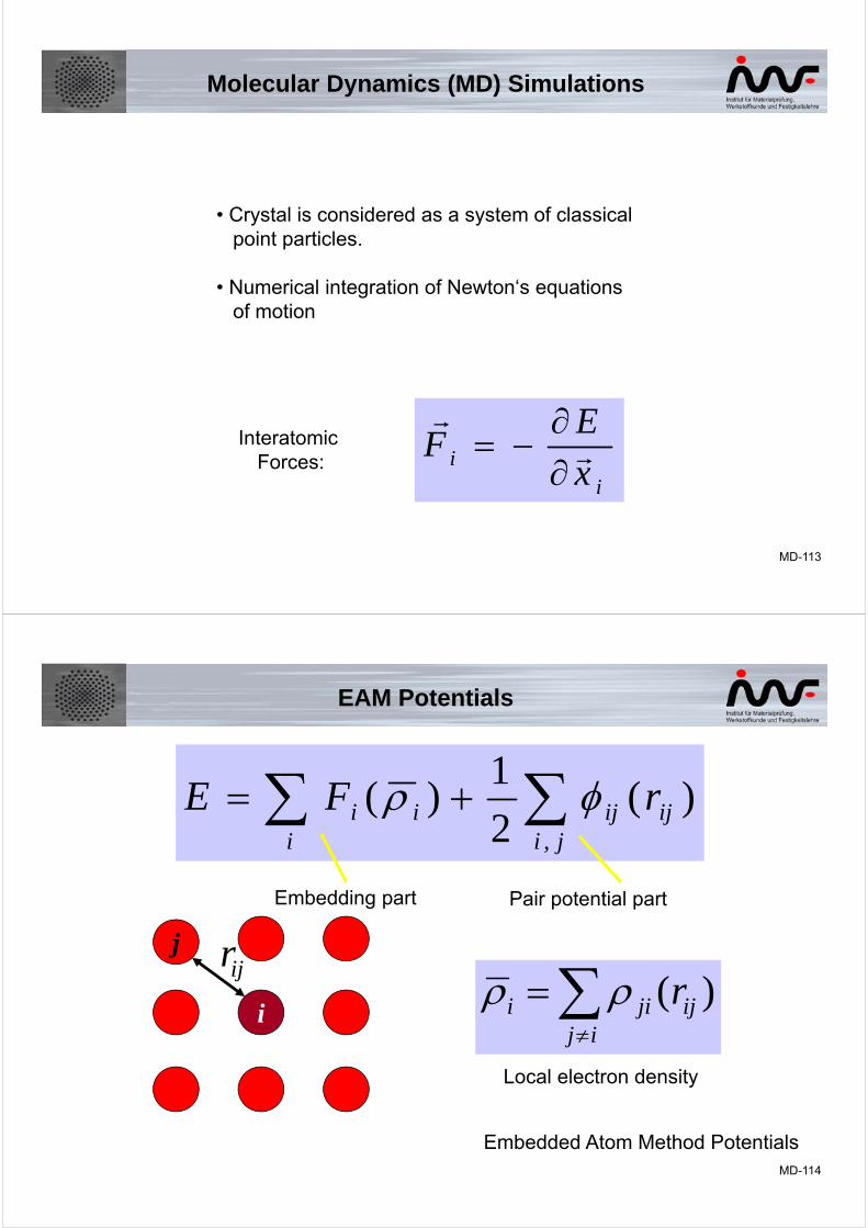
Molecular Dynamics (MD) Simulations
• Crystal is considered as a system of classical point particles.
• Numerical integration of Newton‘s equationsof motion
ii x
EF
Interatomic Forces:
MD-114
EAM Potentials
)(2
1)(
,
jiijiji
ii rFE
)( ijij
jii r
j
i
ijr
Embedding part Pair potential part
Local electron density
Embedded Atom Method Potentials

MD-115
Ideal LatticeOne Fe atom
replaced by a void
One Fe atom
replaced by a H atomFe-Lattice
(1 1 0)
(1 -1 0)
Not deformed
deformed
(36%)
Hydrogen Embrittlement, Mechanism 1: Weakening of Bonds
MD-116
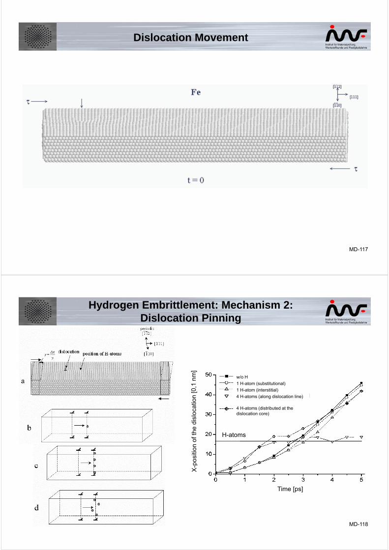
Edge Dislocation Movement
(I Ī 0) slip plane, Burgers Vector ½ [ I I I ]
MD-117
Dislocation Movement
MD-118
Time [ps]
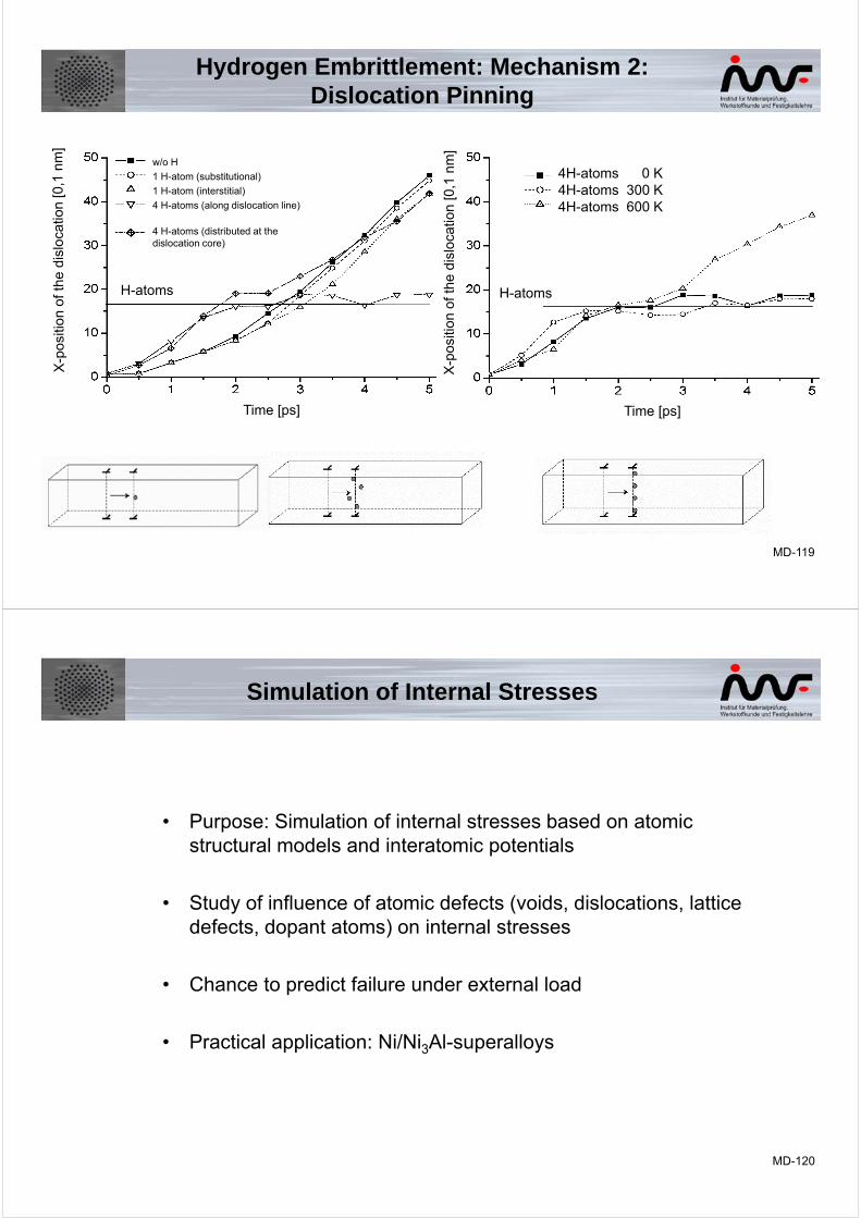
w/o H
1 H-atom (substitutional)
1 H-atom (interstitial)
4 H-atoms (along dislocation line)
4 H-atoms (distributed at the dislocation core)
H-atoms
Hydrogen Embrittlement: Mechanism 2: Dislocation Pinning
MD-119
H-atoms
4H-atoms 0 K4H-atoms 300 K4H-atoms 600 K
Time [ps]
X-p
ositi
on o
f the
dis
loca
tion
[0,1
nm
]
Time [ps]
w/o H
1 H-atom (substitutional)
1 H-atom (interstitial)
4 H-atoms (along dislocation line)
4 H-atoms (distributed at the dislocation core)
H-atoms
Hydrogen Embrittlement: Mechanism 2: Dislocation Pinning
MD-120
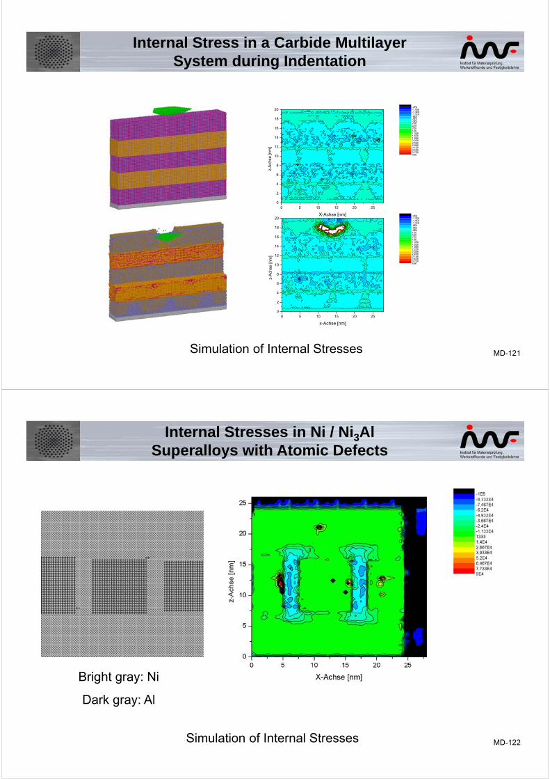
Simulation of Internal Stresses
• Purpose: Simulation of internal stresses based on atomic structural models and interatomic potentials
• Study of influence of atomic defects (voids, dislocations, lattice defects, dopant atoms) on internal stresses
• Chance to predict failure under external load
• Practical application: Ni/Ni3Al-superalloys
MD-121
Internal Stress in a Carbide MultilayerSystem during Indentation
Simulation of Internal Stresses
0 5 10 15 20 250
2
4
6
8
10
12
14
16
18
20
X-Achse [nm]
z-A
chse
[nm
]
-2E6-1,7E6-1,4E6-1,1E6-8E5-5E5-2E51E54E57E51E61,3E61,6E61,9E62,2E62,5E62,8E63,1E63,4E63,7E64E6
0 5 10 15 20 250
2
4
6
8
10
12
14
16
18
20
x-Achse [nm]
z-A
chse
[nm
]
-2E6-1,7E6-1,4E6-1,1E6-8E5-5E5-2E51E54E57E51E61,3E61,6E61,9E62,2E62,5E62,8E63,1E63,4E63,7E64E6
MD-122
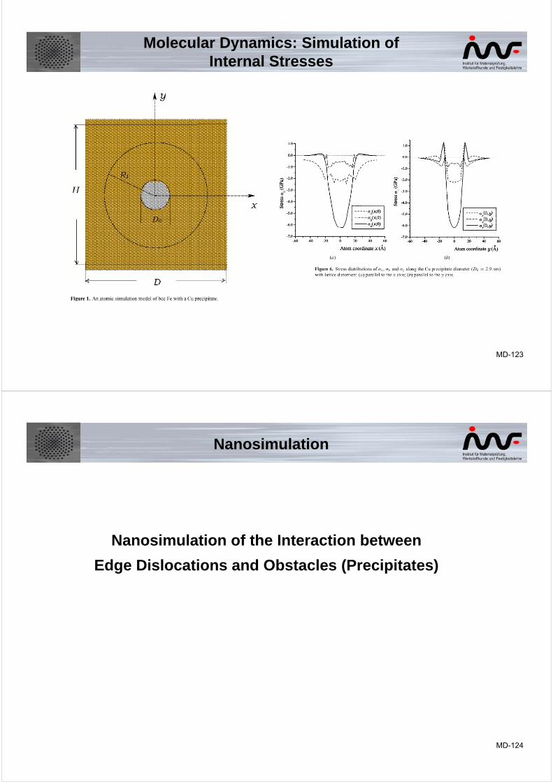
Internal Stresses in Ni / Ni3AlSuperalloys with Atomic Defects
Simulation of Internal Stresses
Bright gray: Ni
Dark gray: Al
MD-123
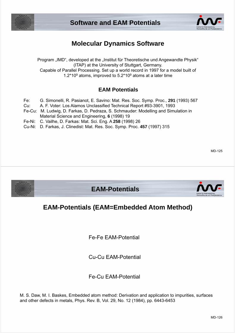
Molecular Dynamics: Simulation ofInternal Stresses
MD-124
Nanosimulation of the Interaction between
Edge Dislocations and Obstacles (Precipitates)
Nanosimulation
MD-125
EAM Potentials
Fe: G. Simonelli, R. Pasianot, E. Savino: Mat. Res. Soc. Symp. Proc., 291 (1993) 567Cu: A. F. Voter: Los Alamos Unclassified Technical Report #93-3901, 1993Fe-Cu: M. Ludwig, D. Farkas, D. Pedraza, S. Schmauder: Modelling and Simulation in
Material Science and Engineering, 6 (1998) 19Fe-Ni: C. Vailhe, D. Farkas: Mat. Sci. Eng. A 258 (1998) 26Cu-Ni: D. Farkas, J. Clinedist: Mat. Res. Soc. Symp. Proc. 457 (1997) 315
Molecular Dynamics Software
Program „IMD“, developed at the „Institut für Theoretische und Angewandte Physik“ (ITAP) at the University of Stuttgart, Germany.
Capable of Parallel Processing. Set up a world record in 1997 for a model built of1.2*109 atoms, improved to 5.2*109 atoms at a later time
Software and EAM Potentials
MD-126
EAM-Potentials
EAM-Potentials (EAM=Embedded Atom Method)
Fe-Fe EAM-Potential
Cu-Cu EAM-Potential
Fe-Cu EAM-Potential
M. S. Daw, M. I. Baskes, Embedded atom method: Derivation and application to impurities, surfaces and other defects in metals, Phys. Rev. B, Vol. 29, No. 12 (1984), pp. 6443-6453
MD-127
)(:)(
)(:)exp(
)(
212
2102
2
1
4
1
3
21
xxxxhxhhxx
xxx
x
xzHzxax
R
FRE
a
i
i
ii
ij
ij
ai
i
i
ji
ijtot
Fe-Fe EAM-Potenital
Param. Experiment Calculateda0 0.2866 nm 0.2876 nmEcoh 4.28 eV 4.28 eVc11 241 GPa 248 GPac12 143 GPa 152 GPac44 118 GPa 113 GPaEv,for 1.8 eV 1.6 eV
Adjusted to: lattice parameter a0, cohesive energy Ecoh, elastic constants cij, vacancy formation energy EV,for
G. Simonelli, R. Pasianot, E. J. Savino, Mat. Res. Soc. Symp. Proc., 291 (1993) 567
MD-128
rra
MRr
M
ij
ij
ai
i
i
ji
ijtot
eer
DeDr
R
FRE
MM
296
2
21
2
1)(
A. F. Voter, Los Alamos Unclassified Technical Report #93-3901, 1993
Param. Experiment Calculateda0 0.3615 nm 0.3615 nmEcoh 3.54 eV 3.54 eVc11 176 GPa 180 GPac12 125 GPa 122 GPac44 82 GPa 82 GPaEv,for 1.3 eV 1.3 eV
Adjusted to: lattice parameter a0, cohesive energy Ecoh, elastic constants cij, vacancy formation energy EV,for
Cu-Cu EAM-Potential
MD-129
Fe-Cu EAM-Potential
fxedxcbxa
R
FRE
Fwithrandr
CuFeFeCu
ij
ij
ji
i
i
ji
ijtot
lCuFe
21
)(
0)(:
21
0
M. Ludwig, D. Farkas, D. Pedraza, S. Schmauder, Modelling and Simulation in Material Science and Engineering, 6, pp. 19-28 (1998)
Point defects in Fe, periodic boundary conditions, constant volume, 686 atoms
x=0...1. Parameter: a=1.0, b=4.7, c=0.99, d=4.095, e=1.0, f=4.961
Param. Experiment CalculatedEV 1.8 eV 1.6 eVECu 1.233 eV 1.236 eVEV-Cu 0.14 eV 0.18 eVE2Cu 0.19 eVEk(2) 0.05 eV 0.01 eV
b
b
b
MD-130
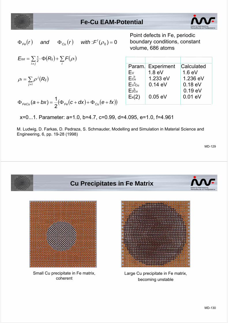
Small Cu precipitate in Fe matrix,coherent
Large Cu precipitate in Fe matrix,
becoming unstable
Cu Precipitates in Fe Matrix
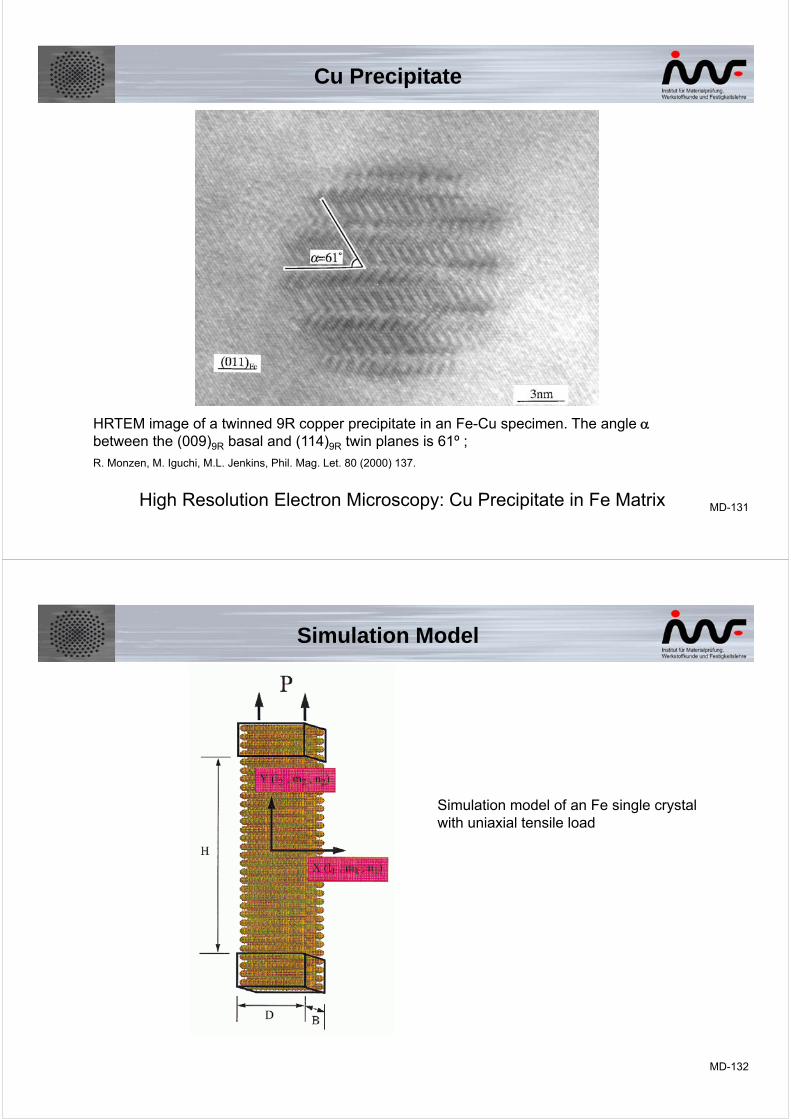
MD-131High Resolution Electron Microscopy: Cu Precipitate in Fe Matrix
HRTEM image of a twinned 9R copper precipitate in an Fe-Cu specimen. The angle between the (009)9R basal and (114)9R twin planes is 61º ;
R. Monzen, M. Iguchi, M.L. Jenkins, Phil. Mag. Let. 80 (2000) 137.
Cu Precipitate
MD-132
Simulation Model
Simulation model of an Fe single crystal with uniaxial tensile load
MD-133
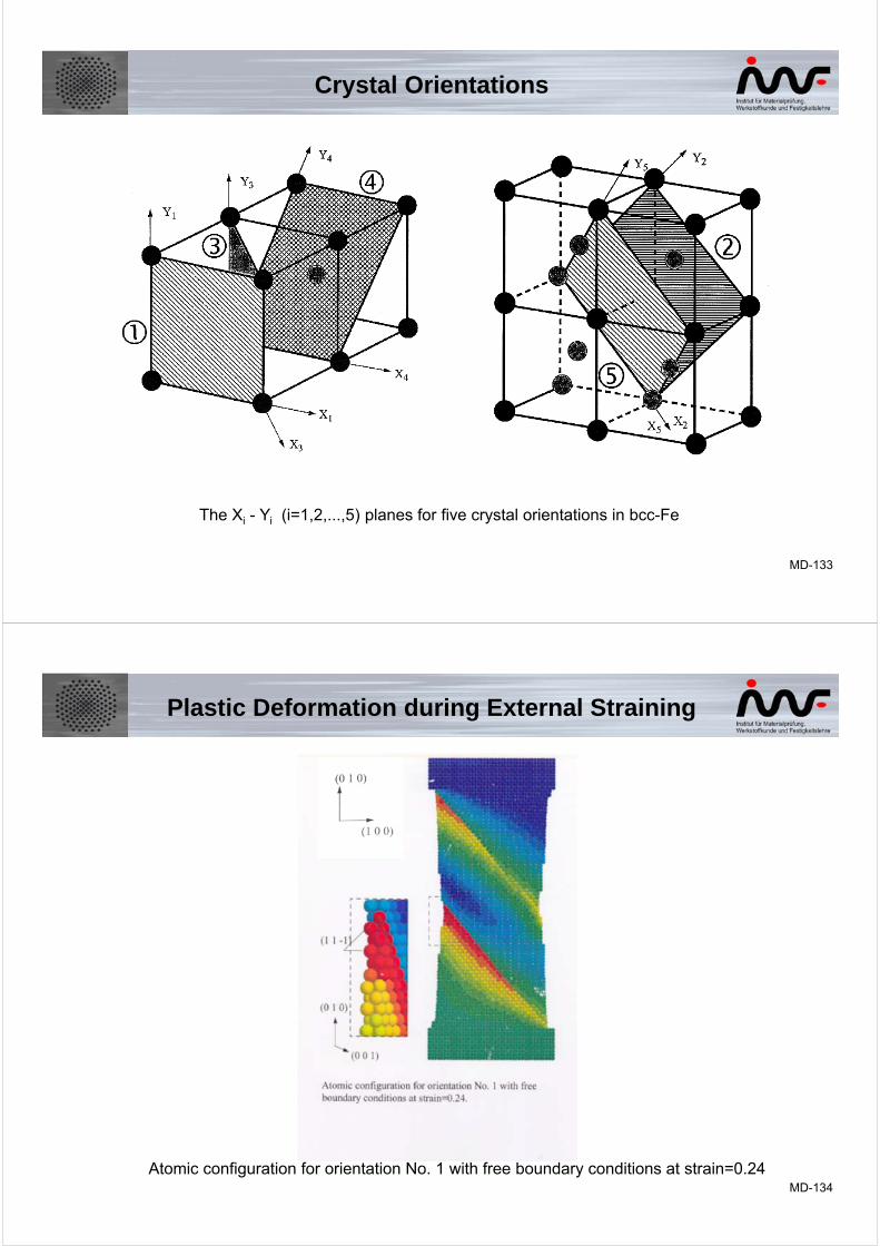
The Xi - Yi (i=1,2,...,5) planes for five crystal orientations in bcc-Fe
Crystal Orientations
MD-134
Atomic configuration for orientation No. 1 with free boundary conditions at strain=0.24
Plastic Deformation during External Straining
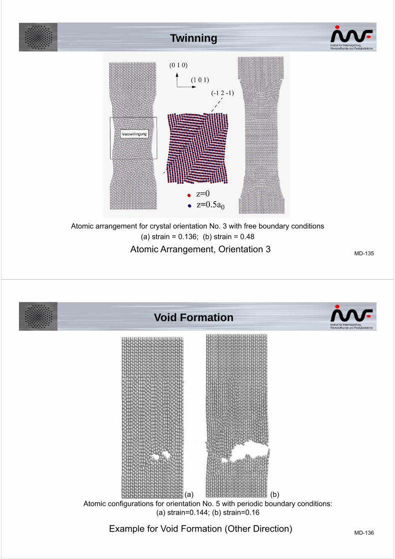
MD-135Atomic Arrangement, Orientation 3
Atomic arrangement for crystal orientation No. 3 with free boundary conditions
(a) strain = 0.136; (b) strain = 0.48
Twinning
MD-136Example for Void Formation (Other Direction)
(a) (b)Atomic configurations for orientation No. 5 with periodic boundary conditions:
(a) strain=0.144; (b) strain=0.16
Void Formation
MD-137
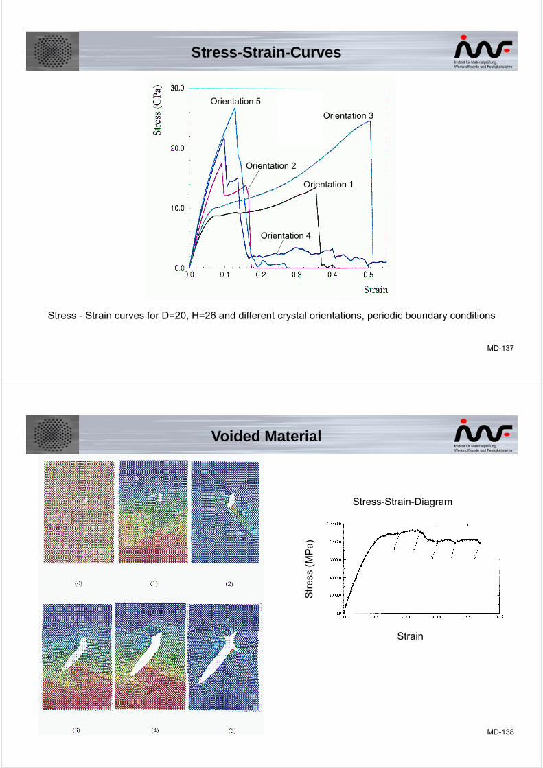
Stress - Strain curves for D=20, H=26 and different crystal orientations, periodic boundary conditions
Stress-Strain-Curves
Orientation 1
Orientation 2
Orientation 4
Orientation 5
Orientation 3
MD-138
Strain
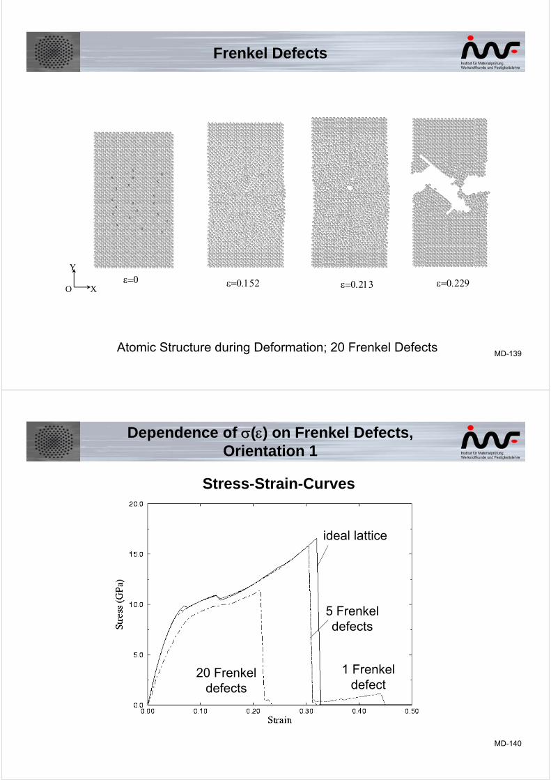
Stress-Strain-Diagram
Voided Material
MD-139
Y
O X
X
X
X
XX
X X
X
XX
XXX
XXX
XX
XX
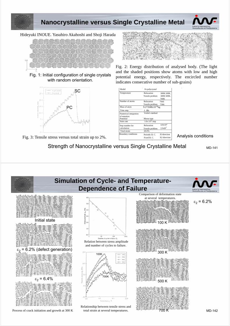
Atomic Structure during Deformation; 20 Frenkel Defects
Frenkel Defects
MD-140
Dependence of () on Frenkel Defects, Orientation 1
Stress-Strain-Curves
ideal lattice
1 Frenkeldefect
20 Frenkeldefects
5 Frenkeldefects
MD-141
Hideyuki INOUE. Yasuhiro Akahoshi and Shoji Harada
Fig. 1: Initial configuration of single crystals with random orientation.
Fig. 2: Energy distribution of analysed body. (The lightand the shaded positions show atoms with low and highpotential energy, respectively. The encircled numberindicates consecutive number of sub-grains)
Fig. 3: Tensile stress versus total strain up to 2%.
Model Fe polycrystal
Temperature RelaxationTensile problem
300K 100K.300K 500K.700K
Number of atoms RelaxationTensile problem
794S7306
Mass of atom 9.273588x10⁻²⁶kgTime step 1 .0 fsNumerical integrationof equation
Verlet's method
Potential Morse typepotentialStain rate 1.0x l.0-1/ step
Step number forcalculation
Relaxation
Tensile problem
4.0x10⁴
2.0xl02
Total strain 20.0%
Boundary conditions Periodic B. C.
Fixed B. C.
X1 direction
X2 direction
Strength of Nanocrystalline versus Single Crystalline Metal
Nanocrystalline versus Single Crystalline Metal
Analysis conditions
SC
PC
MD-142
Simulation of Cycle- and Temperature-Dependence of Failure
Comparison of deformation stateat several temperatures.
Relation between stress amplitude and number of cycles to failure.
Process of crack initiation and growth at 300 KRelationship between tensile stress and
total strain at several temperatures.
700K
100K
Initial state
2 = 6.2% (defect generation)
2 = 6.4%
100 K
300 K
500 K
700 K
2 = 6.2%
MD-143
Schematic representation of a section through the sample, showing the initial position of the edge dislocations and the Cu atoms (grey).
The interaction between a moving edge dislocation in an Fe crystal and a Cu-precipitate is investigated by molecular dynamics (MD) calculations.
In the absence of external stresses, two edge dislocations with the same slip plane and opposite Burgers vectors within a perfect Fe crystal lattice are investigated.
Initial Positions of the Edge Dislocations
Nanosimulation of the Interaction between Edge Dislocations and Obstacles (Precipitates)
MD-144
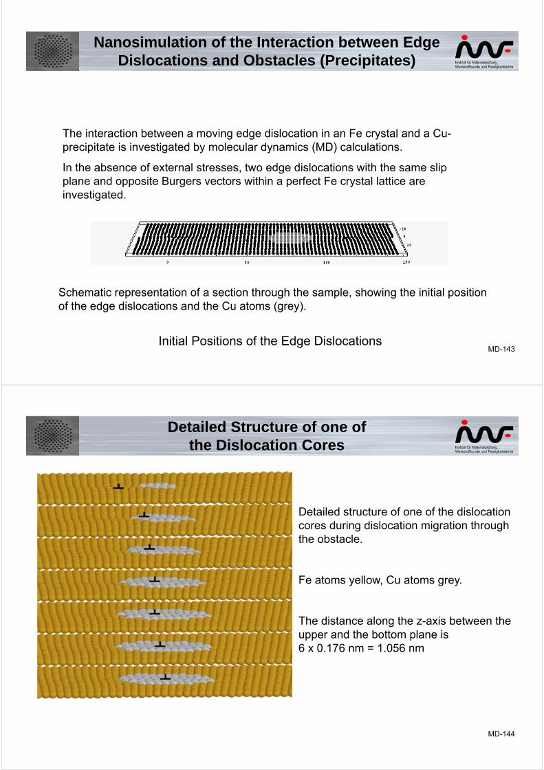
Detailed Structure of one ofthe Dislocation Cores
Detailed structure of one of the dislocation cores during dislocation migration through the obstacle.
Fe atoms yellow, Cu atoms grey.
The distance along the z-axis between the upper and the bottom plane is 6 x 0.176 nm = 1.056 nm
MD-145
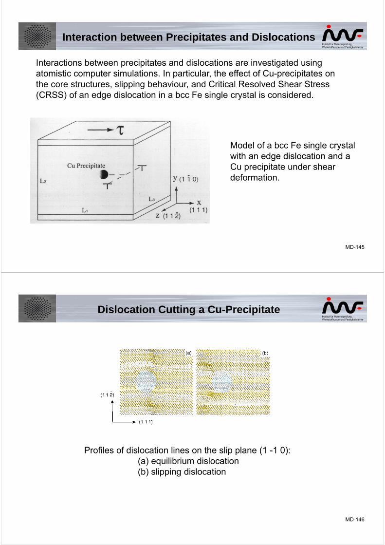
Interactions between precipitates and dislocations are investigated using atomistic computer simulations. In particular, the effect of Cu-precipitates on the core structures, slipping behaviour, and Critical Resolved Shear Stress (CRSS) of an edge dislocation in a bcc Fe single crystal is considered.
Model of a bcc Fe single crystal with an edge dislocation and a Cu precipitate under shear deformation.
Interaction between Precipitates and Dislocations
MD-146
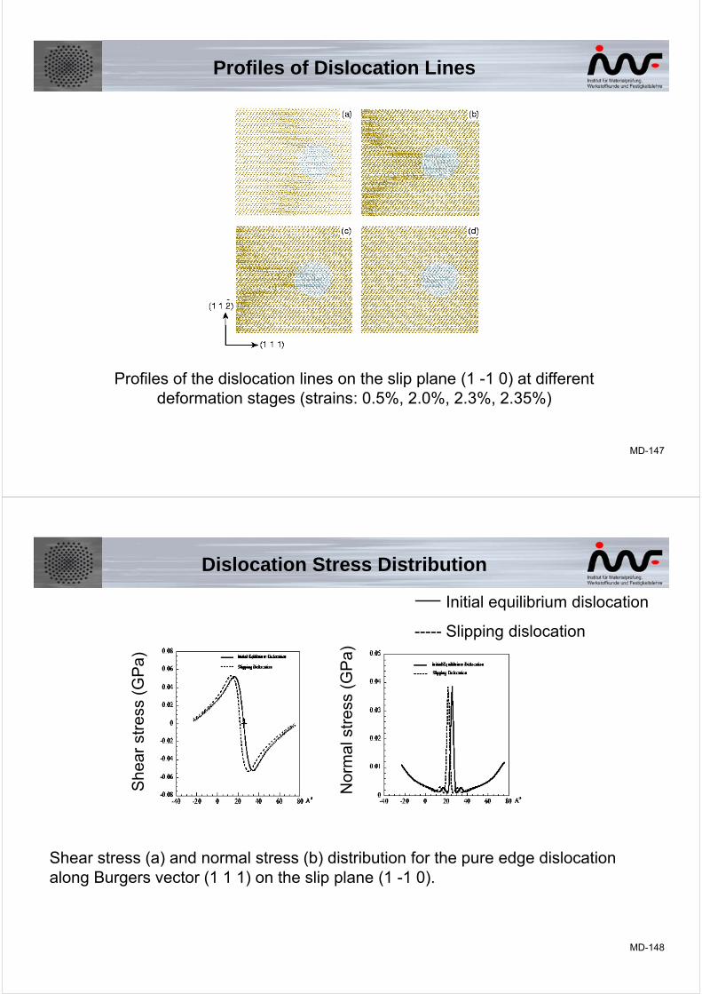
Profiles of dislocation lines on the slip plane (1 -1 0):(a) equilibrium dislocation(b) slipping dislocation
Dislocation Cutting a Cu-Precipitate
MD-147
Profiles of the dislocation lines on the slip plane (1 -1 0) at different deformation stages (strains: 0.5%, 2.0%, 2.3%, 2.35%)
Profiles of Dislocation Lines
MD-148
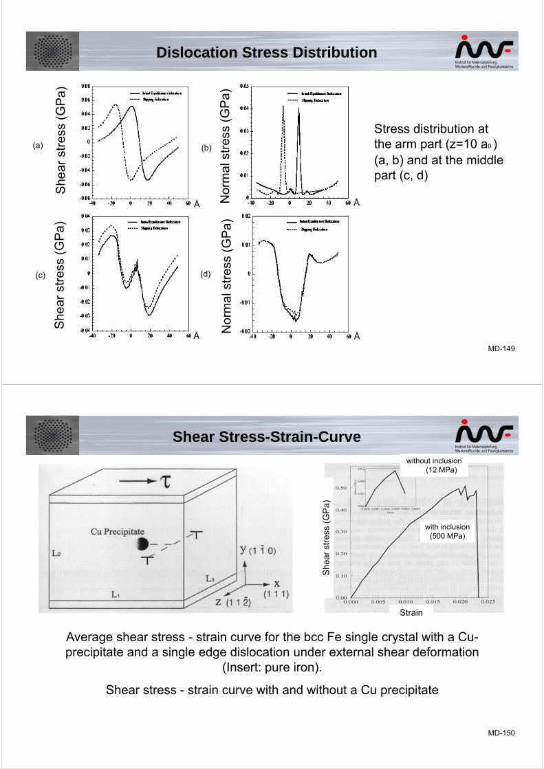
Shear stress (a) and normal stress (b) distribution for the pure edge dislocation along Burgers vector (1 1 1) on the slip plane (1 -1 0).
She
ar s
tres
s (G
Pa)
Nor
mal
str
ess
(GP
a)
Initial equilibrium dislocation
----- Slipping dislocation
Dislocation Stress Distribution
MD-149
Stress distribution atthe arm part (z=10 a0 ) (a, b) and at the middlepart (c, d)
She
ar s
tres
s (G
Pa)
Nor
mal
str
ess
(GP
a)
She
ar s
tres
s (G
Pa)
Nor
mal
str
ess
(GP
a)
(a)
(c)
(b)
(d)
Å
ÅÅ
Å
Dislocation Stress Distribution
MD-150
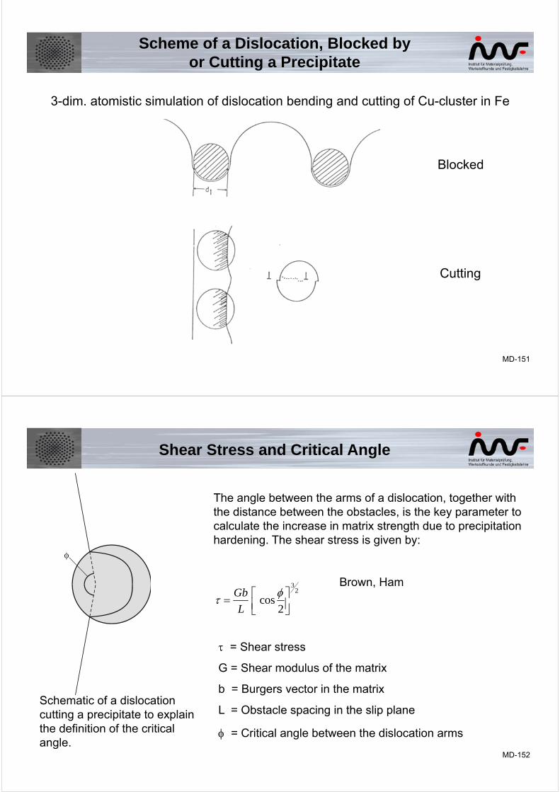
Average shear stress - strain curve for the bcc Fe single crystal with a Cu-precipitate and a single edge dislocation under external shear deformation
(Insert: pure iron).
Shear stress - strain curve with and without a Cu precipitate
Shear Stress-Strain-Curve
She
ar s
tres
s (G
Pa)
Strain
without inclusion(12 MPa)
with inclusion(500 MPa)
MD-151
3-dim. atomistic simulation of dislocation bending and cutting of Cu-cluster in Fe
Scheme of a Dislocation, Blocked byor Cutting a Precipitate
Blocked
Cutting
MD-152
Schematic of a dislocationcutting a precipitate to explainthe definition of the criticalangle.
The angle between the arms of a dislocation, together with the distance between the obstacles, is the key parameter to calculate the increase in matrix strength due to precipitation hardening. The shear stress is given by:
23
2cos
L
GbBrown, Ham
= Shear stress
G = Shear modulus of the matrix
b = Burgers vector in the matrix
L = Obstacle spacing in the slip plane
= Critical angle between the dislocation arms
Shear Stress and Critical Angle
MD-153
23
2cos
L
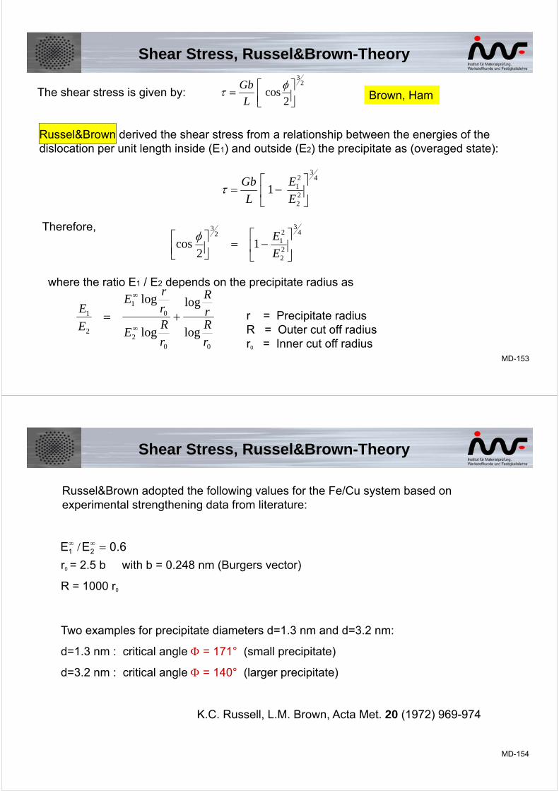
GbBrown, HamThe shear stress is given by:
Russel&Brown derived the shear stress from a relationship between the energies of thedislocation per unit length inside (E1) and outside (E2) the precipitate as (overaged state):
43
22
211
E
E
L
Gb
Therefore,4
3
22
21
23
12
cos
E
E
where the ratio E1 / E2 depends on the precipitate radius as
002
01
2
1
log
log
log
log
rRrR
rR
E
rr
E
E
E
r = Precipitate radius R = Outer cut off radiusr0 = Inner cut off radius
Shear Stress, Russel&Brown-Theory
MD-154
Russel&Brown adopted the following values for the Fe/Cu system based on experimental strengthening data from literature:
r0 = 2.5 b with b = 0.248 nm (Burgers vector)
R = 1000 r0
Two examples for precipitate diameters d=1.3 nm and d=3.2 nm:
d=1.3 nm : critical angle = 171° (small precipitate)
d=3.2 nm : critical angle = 140° (larger precipitate)
K.C. Russell, L.M. Brown, Acta Met. 20 (1972) 969-974
0.6EE 21 /
Shear Stress, Russel&Brown-Theory
MD-155
Larger Precipitate, Diameter 3.04 nm
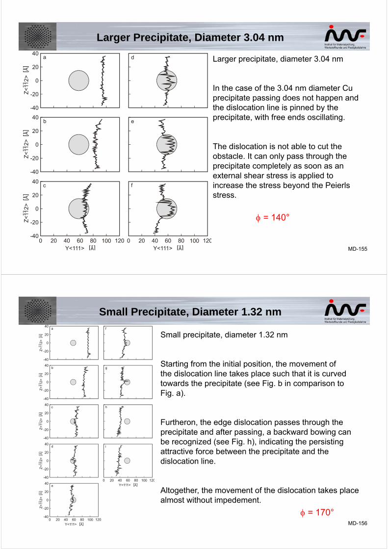
Larger precipitate, diameter 3.04 nm
In the case of the 3.04 nm diameter Cu precipitate passing does not happen and the dislocation line is pinned by the precipitate, with free ends oscillating.
The dislocation is not able to cut the obstacle. It can only pass through the precipitate completely as soon as an external shear stress is applied to increase the stress beyond the Peierls stress.
= 140°
MD-156
Small Precipitate, Diameter 1.32 nm
Small precipitate, diameter 1.32 nm
Starting from the initial position, the movement ofthe dislocation line takes place such that it is curvedtowards the precipitate (see Fig. b in comparison toFig. a).
Furtheron, the edge dislocation passes through theprecipitate and after passing, a backward bowing canbe recognized (see Fig. h), indicating the persistingattractive force between the precipitate and thedislocation line.
Altogether, the movement of the dislocation takes placealmost without impedement.
= 170°