Embed Size (px)
Citation preview
Coules, H. E. (2017). Interaction of surface cracks subjected to non-uniformdistributions of stress. International Journal of Pressure Vessels and Piping,157, 20-29. DOI: 10.1016/j.ijpvp.2017.08.002
Publisher's PDF, also known as Version of record
License (if available):CC BY
Link to published version (if available):10.1016/j.ijpvp.2017.08.002
Link to publication record in Explore Bristol ResearchPDF-document
This is the final published version of the article (version of record). It first appeared online via Elsevier athttp://www.sciencedirect.com/science/article/pii/S0308016117301862. Please refer to any applicable terms ofuse of the publisher.
University of Bristol - Explore Bristol ResearchGeneral rights
This document is made available in accordance with publisher policies. Please cite only the publishedversion using the reference above. Full terms of use are available:http://www.bristol.ac.uk/pure/about/ebr-terms

Take down policy
Explore Bristol Research is a digital archive and the intention is that deposited content should not beremoved. However, if you believe that this version of the work breaches copyright law please [email protected] and include the following information in your message:
• Your contact details• Bibliographic details for the item, including a URL• An outline of the nature of the complaint
On receipt of your message the Open Access Team will immediately investigate your claim, make aninitial judgement of the validity of the claim and, where appropriate, withdraw the item in questionfrom public view.

lable at ScienceDirect
International Journal of Pressure Vessels and Piping 157 (2017) 20e29
Contents lists avai
International Journal of Pressure Vessels and Piping
journal homepage: www.elsevier .com/locate/ i jpvp
Interaction of surface cracks subjected to non-uniform distributions ofstress
H.E. CoulesDepartment of Mechanical Engineering, University of Bristol, Bristol, BS8 1TR, UK
a r t i c l e i n f o
Article history:Received 22 May 2017Received in revised form21 August 2017Accepted 22 August 2017Available online 4 September 2017
Keywords:InteractionSurface crackStructural integrity assessmentResidual stressThermal stress
E-mail address: [email protected].
http://dx.doi.org/10.1016/j.ijpvp.2017.08.0020308-0161/© 2017 The Author. Published by Elsevier
a b s t r a c t
Closely-spaced surface cracks in structures interact with each other when subjected to load. The degreeof interaction depends strongly on the distribution of stress that is applied. In pressure boundarycomponents, thermal shock, residual stress and global bending can all cause load distributions that arenon-uniform through the wall thickness. A wide range of crack pairs subject to various non-uniformstress distributions have been modelled using finite element analysis. Cracks sometimes interact morestrongly under non-uniform loading than when loaded in uniform tension. Consequently, interactioncriteria developed by considering uniform tension may not be inherently conservative for all loadingconditions. A simple weight function method for determining the interaction of twin cracks under anarbitrary through-wall stress is presented, and weight function coefficients for a wide range of crack sizesand aspect ratios are given.
© 2017 The Author. Published by Elsevier Ltd. This is an open access article under the CC BY license(http://creativecommons.org/licenses/by/4.0/).
1. Introduction
Most procedures for structural integrity assessment includerules for establishing whether two or more closely-spaced defectsin a structure interact. When performing an integrity assessment, itis often useful to know whether failure mechanisms that areinitiated by the presence of a defect are influenced by the presenceof other defects nearby. This tells the assessor whether the defectscan be considered individually or whether they will have to beconsidered jointly. If the interaction is significant and the defectsneed to be jointly considered, this can increase the complexity ofthe analysis. It can also introduce additional conservatism if theinteraction can only be accounted for in an approximate manner.
Many structural integrity assessment procedures, including R6[1] and BS 7910 [2], include simplified interaction criteria that arelargely based on Linear Elastic Fracture Mechanics (LEFM). It isassumed that if two crack-like defects are close enough for thestress intensity factor at each to be affected significantly by thepresence of the other, then other failure mechanisms may beaffected likewise. For example, fatigue crack propagation underMode I loading is normally assumed to be controlled by the vari-ation in KI . Therefore, the fatigue crack growth rate at one crack canbe affected by the proximity of another and this can affect how the
Ltd. This is an open access article
cracks coalesce [3e5].Two-dimensional cracks in the through-thickness plane (as
shown in Fig. 1) are a particularly important concern for theintegrity of pressure vessels. The orientation of such defects meansthat they can be subjected to opening-mode stresses due to pres-surisation, thermal shock and welding/cladding residual stresses.Furthermore, defects of this type can be created by solidificationcracking in welds during manufacture or by environmentally-assisted cracking during service. These cracks can be subjected todistributions of stress which vary significantly through the thick-ness of the pressure vessel wall (Fig. 1). Stress distributions thatvary through the wall thickness can be caused by thermal shock,residual stress or local bulging of the pressure vessel. In thick-walled pressure vessels the circumferential stress due to pressur-isation is inherently non-uniform, and is greatest at the internalsurface.
Although it is known that adjacent cracks in a linear-elasticmaterial interact to a greater or lesser degree depending on thethrough-thickness stress distribution, all widely-used code criteriafor judging whether two co-planar cracks will interact are basedpurely on the geometry of the defects and are independent of theirloading mode. This includes the criteria used by the ASME B&PVCSection XI [6], JSME S NA1 [7], API 579e1 [8], R6 [1], BS 7910 [2], GB/T 19624e2004 [9] and SSM 2008:01 [10] assessment procedures.The effect of through-wall variations in stress on crack interactionhas been investigated by several groups of researchers. Using the
under the CC BY license (http://creativecommons.org/licenses/by/4.0/).
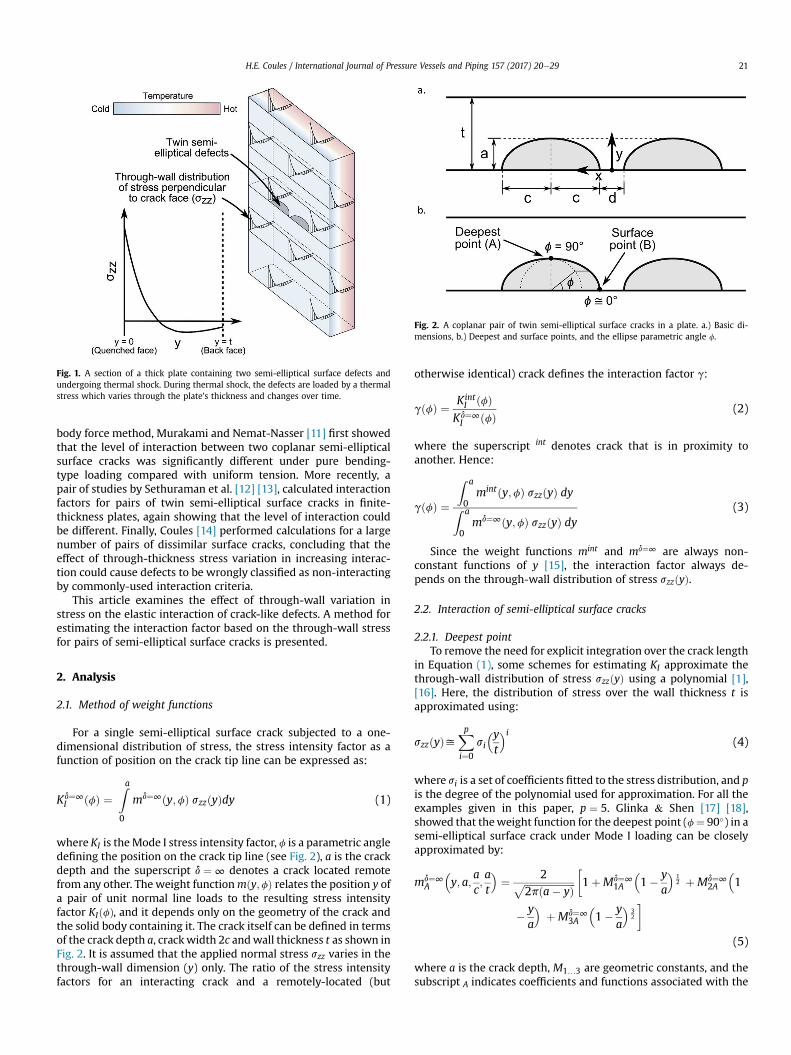
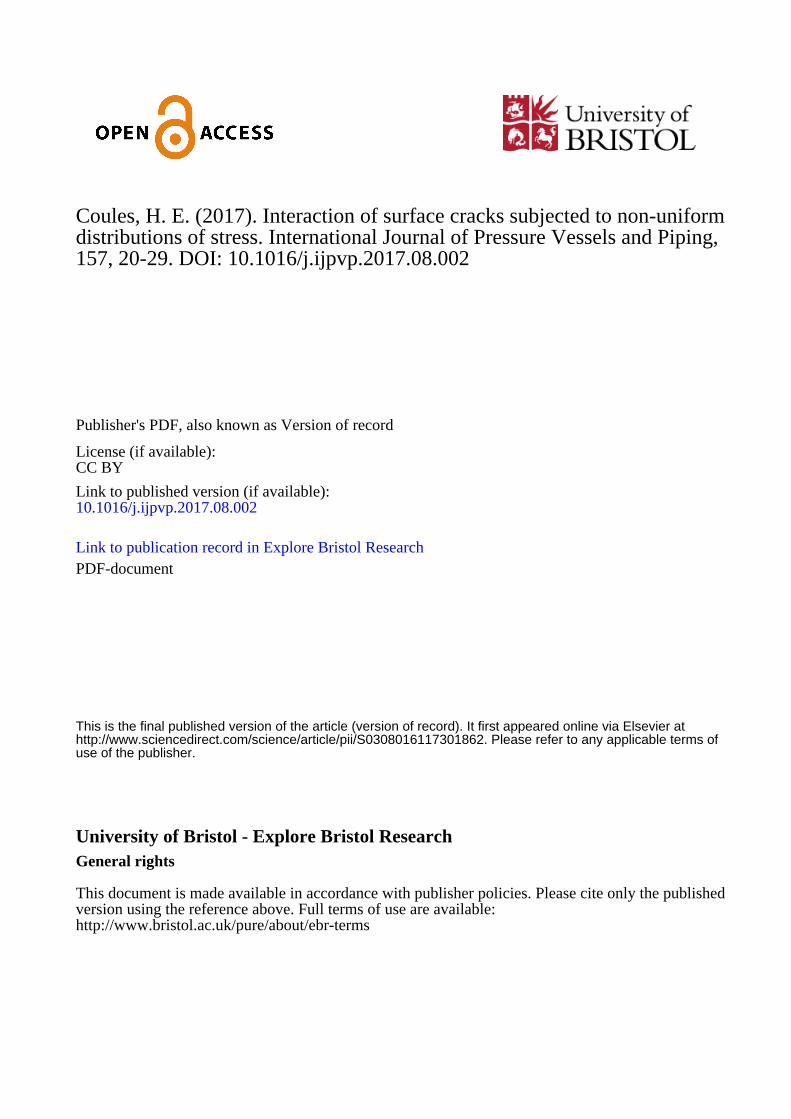
Fig. 1. A section of a thick plate containing two semi-elliptical surface defects andundergoing thermal shock. During thermal shock, the defects are loaded by a thermalstress which varies through the plate's thickness and changes over time.
Fig. 2. A coplanar pair of twin semi-elliptical surface cracks in a plate. a.) Basic di-mensions, b.) Deepest and surface points, and the ellipse parametric angle f.
H.E. Coules / International Journal of Pressure Vessels and Piping 157 (2017) 20e29 21
body force method, Murakami and Nemat-Nasser [11] first showedthat the level of interaction between two coplanar semi-ellipticalsurface cracks was significantly different under pure bending-type loading compared with uniform tension. More recently, apair of studies by Sethuraman et al. [12] [13], calculated interactionfactors for pairs of twin semi-elliptical surface cracks in finite-thickness plates, again showing that the level of interaction couldbe different. Finally, Coules [14] performed calculations for a largenumber of pairs of dissimilar surface cracks, concluding that theeffect of through-thickness stress variation in increasing interac-tion could cause defects to be wrongly classified as non-interactingby commonly-used interaction criteria.
This article examines the effect of through-wall variation instress on the elastic interaction of crack-like defects. A method forestimating the interaction factor based on the through-wall stressfor pairs of semi-elliptical surface cracks is presented.
2. Analysis
2.1. Method of weight functions
For a single semi-elliptical surface crack subjected to a one-dimensional distribution of stress, the stress intensity factor as afunction of position on the crack tip line can be expressed as:
Kd¼∞I ðfÞ ¼
Za
0
md¼∞ðy;fÞ szzðyÞdy (1)
where KI is theMode I stress intensity factor, f is a parametric angledefining the position on the crack tip line (see Fig. 2), a is the crackdepth and the superscript d ¼ ∞ denotes a crack located remotefrom any other. The weight functionmðy;fÞ relates the position y ofa pair of unit normal line loads to the resulting stress intensityfactor KIðfÞ, and it depends only on the geometry of the crack andthe solid body containing it. The crack itself can be defined in termsof the crack depth a, crackwidth 2c andwall thickness t as shown inFig. 2. It is assumed that the applied normal stress szz varies in thethrough-wall dimension (y) only. The ratio of the stress intensityfactors for an interacting crack and a remotely-located (but
otherwise identical) crack defines the interaction factor g:
gðfÞ ¼ KintI ðfÞ
Kd¼∞I ðfÞ (2)
where the superscript int denotes crack that is in proximity toanother. Hence:
gðfÞ ¼
Z a
0mintðy;fÞ szzðyÞ dyZ a
0md¼∞ðy;fÞ szzðyÞ dy
(3)
Since the weight functions mint and md¼∞ are always non-constant functions of y [15], the interaction factor always de-pends on the through-wall distribution of stress szzðyÞ.
2.2. Interaction of semi-elliptical surface cracks
2.2.1. Deepest pointTo remove the need for explicit integration over the crack length
in Equation (1), some schemes for estimating KI approximate thethrough-wall distribution of stress szzðyÞ using a polynomial [1],[16]. Here, the distribution of stress over the wall thickness t isapproximated using:
szzðyÞyXpi¼0
si
�yt
�i(4)
where si is a set of coefficients fitted to the stress distribution, and pis the degree of the polynomial used for approximation. For all theexamples given in this paper, p ¼ 5. Glinka & Shen [17] [18],showed that theweight function for the deepest point (f¼ 90�) in asemi-elliptical surface crack under Mode I loading can be closelyapproximated by:
md¼∞A
�y; a;
ac;at
�¼ 2ffiffiffiffiffiffiffiffiffiffiffiffiffiffiffiffiffiffiffiffiffi
2pða� yÞp�1þMd¼∞
1A
�1� y
a
�12 þMd¼∞
2A
�1
� ya
�þMd¼∞
3A
�1� y
a
�32
�
(5)
where a is the crack depth, M1…3 are geometric constants, and thesubscript A indicates coefficients and functions associated with the
H.E. Coules / International Journal of Pressure Vessels and Piping 157 (2017) 20e2922
deepest point on the crack tip line (see Fig. 2b). This functional formcan also be used to approximate theweight function for the deepestpoint in an interacting pair of twin semi-elliptical surface cracks(Fig. 2):
mintA
�y; a;
ac;at;dt
�¼ 2ffiffiffiffiffiffiffiffiffiffiffiffiffiffiffiffiffiffiffiffiffi
2pða� yÞp�1þMint
1A
�1� y
a
�12 þMint
2A
�1
� ya
�þMint
3A
�1� y
a
�32
�
(6)
The constants M1…3 for a given crack geometry can be deter-mined using two reference values of KI for different through-wallloading conditions [18], [19]. Equation (2) can now be solved togive g in terms of si:
gA ¼Pp
i¼0P3
j¼0
�at
�iAijsiMint
jA
Ppi¼0
P3j¼0
�at
�iAijsiMd¼∞
jA
(7)
where the coefficients Aij are given in Table 1, andMint0A ¼ Md¼∞
0A ¼ 1.Using Equation (7), the interaction factor can be found straight-forwardly from the non-uniform stress distribution szzðyÞ withoutexplicit integration over a. Determining the coefficients Md¼∞
1A ,
Md¼∞2A and Md¼∞
3A requires two numerical models of a single surfacedefect: one in which the crack is subjected to uniform tension andonewhere it is subjected to a linearly-decreasing stress distributionwith a finite stress at the surface and zero stress at the deepestpoint [18]. Similarly, determining the coefficients Mint
1A , Mint2A and
Mint3A requires numerical models of the twin surface cracks under
the same two loading conditions.
2.2.2. Surface pointFor points close to the intersection between the tip of a single
semi-elliptical defect and the surface, Shen & Glinka [18] proposeda weight function in the following form:
md¼∞B
�y; a;
ac;at
�¼ 2ffiffiffiffiffiffi
pyp
�1þMd¼∞
1B
�ya
�12 þMd¼∞
2B
�ya
�
þMd¼∞3B
�ya
�32�
(8)
where the subscript B indicates values/functions associated with asurface point. As above, the same functional form can be used for asurface point in a pair of twin semi-elliptical surface defects. Theweight function for a surface intersection point in-between the twocracks is:
Table 1Coefficients of Aij for determining the interaction factor for the deepest point in apair of semi-elliptical surface cracks.
j
0 1 2 3
i 0 2.000000 1.000000 0.666667 0.5000001 1.333333 0.500000 0.266667 0.1666672 1.066667 0.333333 0.152381 0.0833333 0.914286 0.250000 0.101587 0.0500004 0.812698 0.200000 0.073882 0.0333335 0.738817 0.166667 0.056832 0.023810
mintB
�y; a;
ac;at;dt
�¼ 2ffiffiffiffiffiffi
pyp
�1þMint
1B
�ya
�12 þMint
2B
�ya
�þMint
3B
�ya
�32�
(9)
Equation (3) can now be solved in the same manner as Equation(6) to give:
gB ¼Pp
i¼0P3
j¼0
�at
�iBijsiMint
jB
Ppi¼0
P3j¼0
�at
�iBijsiMd¼∞
jB
(10)
for the surface point. The coefficients Bij are given in Table 2 andMint
0B ¼ Md¼∞0B ¼ 1. For materials with ns0, at the intersection be-
tween the crack tip line and the free surface the strength of thestress singularity deviates from sijðqÞfr�1
2 [18], [20]. This creates aboundary layer close to the free surface where the crack tip stressfield is not characterised by KI. However, while the use of a weightfunction for KI to characterise the crack tip stress field at thislocation is theoretically unsound, the ratio g can still be used toindicate the general effect of crack proximity on the stress fieldwhich does occur.
3. Finite element analysis
3.1. Model description
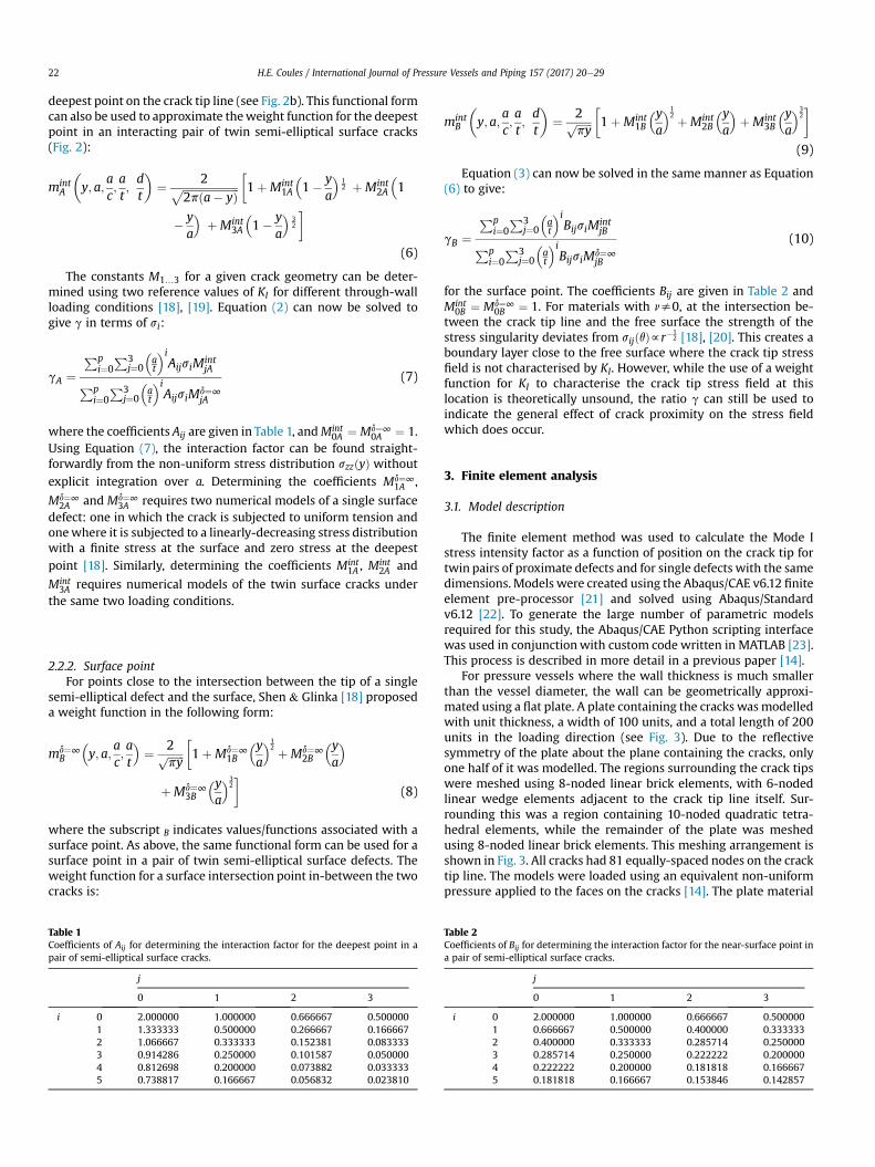
The finite element method was used to calculate the Mode Istress intensity factor as a function of position on the crack tip fortwin pairs of proximate defects and for single defects with the samedimensions. Models were created using the Abaqus/CAE v6.12 finiteelement pre-processor [21] and solved using Abaqus/Standardv6.12 [22]. To generate the large number of parametric modelsrequired for this study, the Abaqus/CAE Python scripting interfacewas used in conjunctionwith custom code written in MATLAB [23].This process is described in more detail in a previous paper [14].
For pressure vessels where the wall thickness is much smallerthan the vessel diameter, the wall can be geometrically approxi-mated using a flat plate. A plate containing the cracks wasmodelledwith unit thickness, a width of 100 units, and a total length of 200units in the loading direction (see Fig. 3). Due to the reflectivesymmetry of the plate about the plane containing the cracks, onlyone half of it was modelled. The regions surrounding the crack tipswere meshed using 8-noded linear brick elements, with 6-nodedlinear wedge elements adjacent to the crack tip line itself. Sur-rounding this was a region containing 10-noded quadratic tetra-hedral elements, while the remainder of the plate was meshedusing 8-noded linear brick elements. This meshing arrangement isshown in Fig. 3. All cracks had 81 equally-spaced nodes on the cracktip line. The models were loaded using an equivalent non-uniformpressure applied to the faces on the cracks [14]. The plate material
Table 2Coefficients of Bij for determining the interaction factor for the near-surface point ina pair of semi-elliptical surface cracks.
j
0 1 2 3
i 0 2.000000 1.000000 0.666667 0.5000001 0.666667 0.500000 0.400000 0.3333332 0.400000 0.333333 0.285714 0.2500003 0.285714 0.250000 0.222222 0.2000004 0.222222 0.200000 0.181818 0.1666675 0.181818 0.166667 0.153846 0.142857

Fig. 3. Meshing arrangement used for finite element analysis of twin surface cracks.
H.E. Coules / International Journal of Pressure Vessels and Piping 157 (2017) 20e29 23
was defined as linear elastic with a Young's modulus of E ¼ 100 GPaand a Poisson's ratio of n ¼ 0:3.
The strain energy release rate was extracted from the finiteelement results using the equivalent domain integral method [24].Since the cracks are under Mode I loading only, the strain energyrelease rate can be related directly to the Mode I stress intensityfactor. For the intersection between the crack tip line and the platesurface, the crack tip node one element away the free surface wasused for stress intensity factor extraction. Using results from boththe single crack and the twin cracks, the interaction factors for thedeepest and surface-intersection points were calculated accordingto Equation (2).
The coefficients needed for the weight function methoddescribed in Section 2.2 were determined from stress intensityfactor results for cracks subjected to uniform tension and purebending. First, superposition was used to determine the stress in-tensity factor for a linearly decreasing stress distribution over thecrack length from the results for tension and pure bending:
KL:D:I ¼ t
2a
�KBend:I �
�1� 2a
t
�KTens:I
�(11)
where KTens:I , KBend:
I , KL:D:I are stress intensity factors for the tension,
bending and linearly decreasing load cases respectively. Theweightfunction coefficients Md¼∞
iA , Md¼∞iB , Mint
iA and MintiB were then deter-
mined using the equations given in Appendix B.
Table 3Parameters used to define 280 models representing pairs of tthe material was defined as n ¼ 0:3.
Parameter
Crack depth at
Crack aspect ratio ac
Normalised separation distance dt
Stress distribution szzðyÞ
3.2. Stress distribution test cases
To test the accuracy of the weight function method, additionalfinite element models were run using three ‘test-case’ stress dis-tributions listed in Table 3. For each of these loading cases, allcombinations of crack depth, aspect ratio and separation distancelisted in Table 3 were modelled. The interaction factors werecalculated directly from the finite element results and thencompared with interaction factors calculated via the weight func-tion method described in Section 2.2.
The first stress distribution listed in Table 4 is taken from thestructural integrity assessment procedure R6 [1]. In that procedure,it is used as a conservative estimate of the distribution of transverseresidual stress in austenitic and ferritic steel plate butt welds. It wasconstructed as an approximate upper bound to a range of measuredand modelled residual stress distributions for such welds. Thesecond test case is the predicted distribution of hoop stress in thewall of aWWER 440Model 213 reactor pressure vessel, 1200 s fromthe start of a thermal shock event initiated by inadvertent openingof the pressuriser safety valve. This distribution was calculated aspart of an IAEA benchmarking study in which six participating or-ganisations independently predicted the through-wall stress dis-tribution using FEA, with good agreement [25]. The 5th-degreepolynomial used to represent it fits closely to the modelled data.The final stress distribution is a simple combination of tension andreverse bending, such that the stress always increases between thesurface y ¼ 0 and the crack tip.
win semi-elliptical surface cracks. The Poisson's ratio of
Values
0.125, 0.25, 0.5, 0.750.3333, 0.5, 0.6667, 1, 1.5, 2, 30.0625, 0.125, 0.25, 0.5, 1
Tension ðszz ¼ 1Þ, Pure bending�szz ¼ 1� 2y
t
�
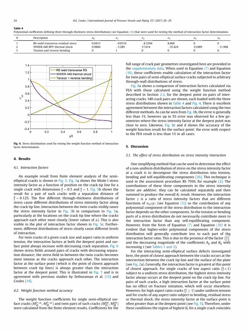
Table 4Polynomial coefficients defining three through-thickness stress distributions (see Equation (4)) that were used for testing the method of interaction factor determination.
# Description s0 s1 s2 s3 s4 s5
1 R6 weld transverse residual stress 0.9415 �0.0319 �8.3394 8.660 0 02 WWER 440 RPV thermal shock 0.9884 �5.289 17.614 �35.424 33.889 �11.9683 Tension and reverse bending 0 1 0 0 0 0
Fig. 4. Stress distributions used for testing the weight function method of interactionfactor determination.
H.E. Coules / International Journal of Pressure Vessels and Piping 157 (2017) 20e2924
4. Results
4.1. Interaction factors
An example result from finite element analysis of the semi-elliptical cracks is shown in Fig. 5. Fig. 5a shows the Mode I stressintensity factor as a function of position on the crack tip line for asingle crack with dimensions a
t ¼ 0:5 and ac ¼ 1. Fig. 5b shows the
result for a pair of such cracks with a separation distance ofdt ¼ 0:125. The five different through-thickness distributions ofstress cause different distributions of stress intensity factor alongthe crack tip line. Interaction between the twin cracks visibly raisesthe stress intensity factor in Fig. 5b in comparison to Fig. 5a,particularly at the locations on the crack tip line where the cracksapproach each other most closely (lower values of f). This is alsovisible in the plot of interaction factor shown in Fig. 5c. Further-more, different distributions of stress clearly cause different levelsof interaction.
For twin cracks of a given crack size and aspect ratio in uniformtension, the interaction factors at both the deepest point and sur-face point always increase with decreasing crack separation. Fig. 6shows stress fields around pairs of cracks with decreasing separa-tion distance; the stress field in-between the twin cracks becomesmore intense as the cracks approach each other. The interactionfactor at the surface point (which is the point of closest approachbetween crack tip lines) is always greater than the interactionfactor at the deepest point. This is illustrated in Fig. 7 and is inagreement with previous studies by Sethuraman et al. [13] andCoules [14].
4.2. Weight function method accuracy
The weight function coefficients for single semi-elliptical sur-face cracks (Md¼∞
iA , Md¼∞iB ) and twin pairs of such cracks (Mint
iA , MintiB )
were calculated from the finite element results. Coefficients for the
full range of crack pair geometries investigated here are provided inthe supplementary data. When used in Equation (7) and Equation(10), these coefficients enable calculation of the interaction factorfor twin pairs of semi-elliptical surface cracks subjected to arbitrarythrough-wall distributions of stress.
Fig. 8a shows a comparison of interaction factors calculated viaFEA with those calculated using the weight function methoddescribed in Section 2.2, for the deepest point on pairs of inter-acting cracks. 140 crack pairs are shown, each loaded with the threestress distributions shown in Table 4 and Fig. 4. There is excellentagreement between the interaction factors calculated using the twodifferentmethods. As can be seen from Fig. 8b, the error is generallyless than 1%, however up to 5% error was observed for a few ge-ometries where the stress intensity factor at the deepest point wasclose to zero. Likewise, Fig. 8c and d shows the accuracy of theweight function result for the surface point: the error with respectto the FEA result is less than 1% in all cases.
5. Discussion
5.1. The effect of stress distribution on stress intensity interaction
One simplifyingmethod that can be used to determine the effectof a non-uniform distribution of stress on the stress intensity factorat a crack is to decompose the stress distribution into tension,bending and self-equilibrating components [26]. This technique isused in the assessment procedure BS 7910, for example [2]. Thecontributions of these three components to the stress intensityfactor are additive: they can be calculated separately and thensummed to produce the overall KI result. However, the interactionfactor g is a ratio of stress intensity factors that are differentfunctions of szzðyÞ (see Equation (3)) so the contribution of anypolynomial component of the stress distribution to the interactionfactor depends on the other components. So the tension or bendingparts of a stress distribution do not necessarily contribute more tothe interaction factor than any self-equilibrating component.However, from the form of Equation (7) and Equation (10) it isevident that higher-order polynomial components of the stressdistribution will generally contribute less to each part of theinteraction factor ratio. This is due to the presence of the factor
�at
�iand the decreasing magnitude of the coefficients Aij and Bij withincreasing i (see Tables 1 and 2).
For the interacting semi-elliptical surface defects investigatedhere, the point of closest approach between the cracks occurs at theintersection between the crack tip line and the surface of the plate(see Fig. 2a). Generally, the interaction factor is greatest at this pointof closest approach. For single cracks of low aspect ratio (ac<1)subject to a uniform stress distribution, the highest stress intensityfactor always occurs at the deepest point on the crack tip line. Forpairs of such cracks, a high interaction factor at the surface pointhas no effect on fracture initiation, which will occur elsewhere.However, for high aspect ratio cracks (ac � 1) under uniform tensionand for cracks of any aspect ratio subject to bending, residual stressor thermal shock, the stress intensity factor at the surface point isoften greater than at the deepest point (see Fig. 5). Therefore, underthese conditions the region of highest KI for a single crack coincides
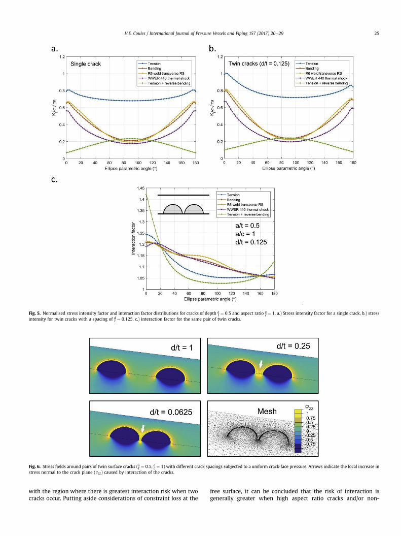
Fig. 5. Normalised stress intensity factor and interaction factor distributions for cracks of depth at ¼ 0:5 and aspect ratio a
c ¼ 1. a.) Stress intensity factor for a single crack, b.) stressintensity for twin cracks with a spacing of d
t ¼ 0:125, c.) interaction factor for the same pair of twin cracks.
Fig. 6. Stress fields around pairs of twin surface cracks (at ¼ 0:5, ac ¼ 1) with different crack spacings subjected to a uniform crack-face pressure. Arrows indicate the local increase instress normal to the crack plane (szz) caused by interaction of the cracks.
H.E. Coules / International Journal of Pressure Vessels and Piping 157 (2017) 20e29 25
with the region where there is greatest interaction risk when twocracks occur. Putting aside considerations of constraint loss at the
free surface, it can be concluded that the risk of interaction isgenerally greater when high aspect ratio cracks and/or non-
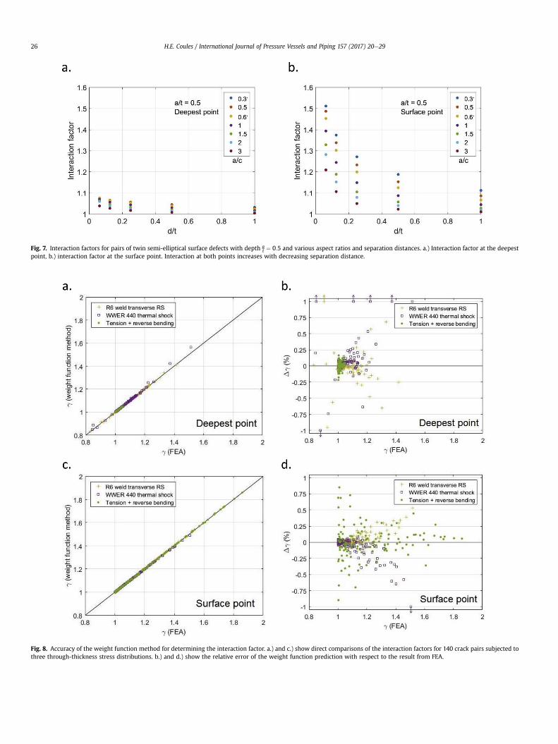
Fig. 7. Interaction factors for pairs of twin semi-elliptical surface defects with depth at ¼ 0:5 and various aspect ratios and separation distances. a.) Interaction factor at the deepest
point, b.) interaction factor at the surface point. Interaction at both points increases with decreasing separation distance.
Fig. 8. Accuracy of the weight function method for determining the interaction factor. a.) and c.) show direct comparisons of the interaction factors for 140 crack pairs subjected tothree through-thickness stress distributions. b.) and d.) show the relative error of the weight function prediction with respect to the result from FEA.
H.E. Coules / International Journal of Pressure Vessels and Piping 157 (2017) 20e2926
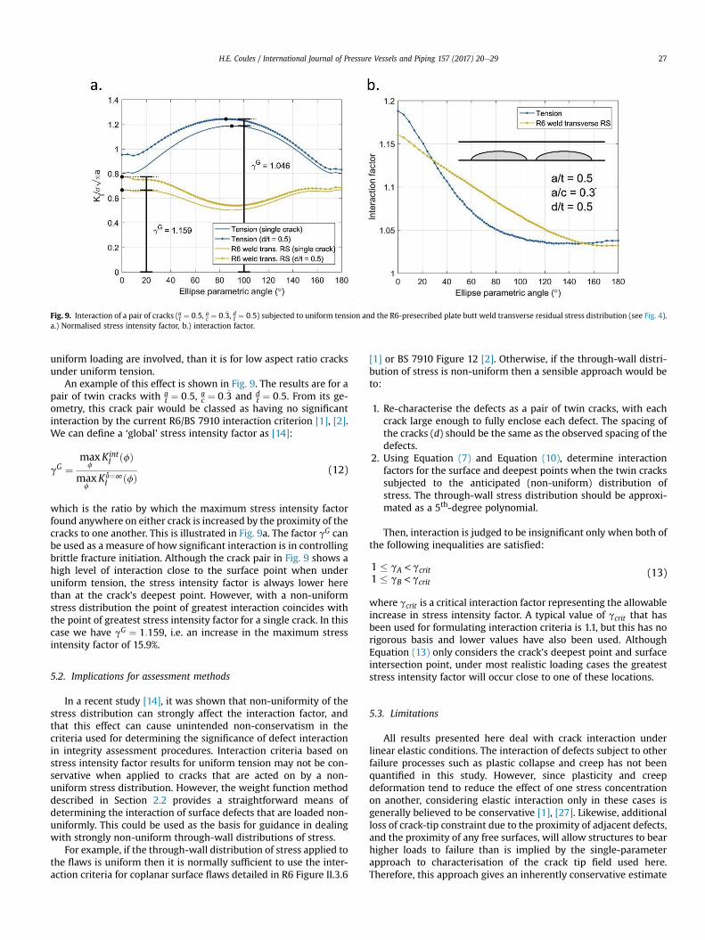
Fig. 9. Interaction of a pair of cracks (at ¼ 0:5, ac ¼ 0: _3, dt ¼ 0:5) subjected to uniform tension and the R6-presecribed plate butt weld transverse residual stress distribution (see Fig. 4).a.) Normalised stress intensity factor, b.) interaction factor.
H.E. Coules / International Journal of Pressure Vessels and Piping 157 (2017) 20e29 27
uniform loading are involved, than it is for low aspect ratio cracksunder uniform tension.
An example of this effect is shown in Fig. 9. The results are for apair of twin cracks with a
t ¼ 0:5, ac ¼ 0: _3 and d
t ¼ 0:5. From its ge-ometry, this crack pair would be classed as having no significantinteraction by the current R6/BS 7910 interaction criterion [1], [2].We can define a ‘global’ stress intensity factor as [14]:
gG ¼max
fKintI ðfÞ
maxf
Kd¼∞I ðfÞ (12)
which is the ratio by which the maximum stress intensity factorfound anywhere on either crack is increased by the proximity of thecracks to one another. This is illustrated in Fig. 9a. The factor gG canbe used as a measure of how significant interaction is in controllingbrittle fracture initiation. Although the crack pair in Fig. 9 shows ahigh level of interaction close to the surface point when underuniform tension, the stress intensity factor is always lower herethan at the crack's deepest point. However, with a non-uniformstress distribution the point of greatest interaction coincides withthe point of greatest stress intensity factor for a single crack. In thiscase we have gG ¼ 1:159, i.e. an increase in the maximum stressintensity factor of 15.9%.
5.2. Implications for assessment methods
In a recent study [14], it was shown that non-uniformity of thestress distribution can strongly affect the interaction factor, andthat this effect can cause unintended non-conservatism in thecriteria used for determining the significance of defect interactionin integrity assessment procedures. Interaction criteria based onstress intensity factor results for uniform tension may not be con-servative when applied to cracks that are acted on by a non-uniform stress distribution. However, the weight function methoddescribed in Section 2.2 provides a straightforward means ofdetermining the interaction of surface defects that are loaded non-uniformly. This could be used as the basis for guidance in dealingwith strongly non-uniform through-wall distributions of stress.
For example, if the through-wall distribution of stress applied tothe flaws is uniform then it is normally sufficient to use the inter-action criteria for coplanar surface flaws detailed in R6 Figure II.3.6
[1] or BS 7910 Figure 12 [2]. Otherwise, if the through-wall distri-bution of stress is non-uniform then a sensible approach would beto:
1. Re-characterise the defects as a pair of twin cracks, with eachcrack large enough to fully enclose each defect. The spacing ofthe cracks (d) should be the same as the observed spacing of thedefects.
2. Using Equation (7) and Equation (10), determine interactionfactors for the surface and deepest points when the twin crackssubjected to the anticipated (non-uniform) distribution ofstress. The through-wall stress distribution should be approxi-mated as a 5th-degree polynomial.
Then, interaction is judged to be insignificant only when both ofthe following inequalities are satisfied:
1 � gA <gcrit1 � gB <gcrit
(13)
where gcrit is a critical interaction factor representing the allowableincrease in stress intensity factor. A typical value of gcrit that hasbeen used for formulating interaction criteria is 1.1, but this has norigorous basis and lower values have also been used. AlthoughEquation (13) only considers the crack's deepest point and surfaceintersection point, under most realistic loading cases the greateststress intensity factor will occur close to one of these locations.
5.3. Limitations
All results presented here deal with crack interaction underlinear elastic conditions. The interaction of defects subject to otherfailure processes such as plastic collapse and creep has not beenquantified in this study. However, since plasticity and creepdeformation tend to reduce the effect of one stress concentrationon another, considering elastic interaction only in these cases isgenerally believed to be conservative [1], [27]. Likewise, additionalloss of crack-tip constraint due to the proximity of adjacent defects,and the proximity of any free surfaces, will allow structures to bearhigher loads to failure than is implied by the single-parameterapproach to characterisation of the crack tip field used here.Therefore, this approach gives an inherently conservative estimate
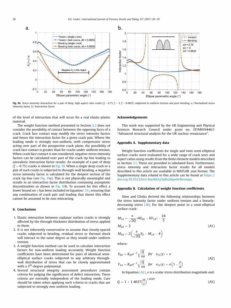
Fig. 10. Stress intensity interaction for a pair of deep, high aspect ratio cracks (at ¼ 0:75, ac ¼ 3, dt ¼ 0:0625) subjected to uniform tension and pure bending. a.) Normalised stressintensity factor, b.) Interaction factor.
H.E. Coules / International Journal of Pressure Vessels and Piping 157 (2017) 20e2928
of the level of interaction that will occur for a real elastic-plasticmaterial.
The weight function method presented in Section 2.2 does notconsider the possibility of contact between the opposing faces of acrack. Crack face contact may modify the stress intensity factorsand hence the interaction factor for a given crack pair. Where theloading mode is strongly non-uniform, with compressive stressacting over part of the prospective crack plane, the possibility ofcrack face contact is greater than for cracks under uniform tension.When crack face contact is not considered, negative stress intensityfactors can be calculated over part of the crack tip line leading tounrealistic interaction factor results. An example of a pair of deep(at ¼ 0:75) cracks is shown in Fig. 10. When a single deep crack or apair of such cracks is subjected to through-wall bending, a negativestress intensity factor is calculated for the deepest section of thecrack tip line (see Fig. 10a). This is not physically meaningful andresults in an interaction factor distribution containing asymptoticdiscontinuities as shown in Fig. 10b. To account for this effect alower bound on g has been included in Equation (13), ensuring thatany combination of crack pair and loading that shows this effectcannot be assumed to be non-interacting.
6. Conclusions
1. Elastic interaction between coplanar surface cracks is stronglyaffected by the through-thickness distribution of stress appliedto them.
2. It is not inherently conservative to assume that closely-spacedcracks subjected to bending, residual stress or thermal shockwill interact to the same degree as they would under uniformtension.
3. A weight function method can be used to calculate interactionfactors for non-uniform loading accurately. Weight functioncoefficients have been determined for pairs of identical semi-elliptical surface cracks subjected to any arbitrary through-wall distribution of stress that can be closely approximatedwith a 5th-degree polynomial.
4. Several structural integrity assessment procedures containcriteria for judging the significance of defect interaction. Thesecriteria are normally independent of the loading mode. Careshould be taken when applying such criteria to cracks that aresubjected to strongly non-uniform loading.
Acknowledgements
This work was supported by the UK Engineering and PhysicalSciences Research Council under grant no. EP/M019446/1“Advanced structural analysis for the UK nuclear renaissance”.
Appendix A. Supplementary data
Weight function coefficients for single and twin semi-ellipticalsurface cracks were evaluated for a wide range of crack sizes andaspect ratios using results from the finite elementmodels describedin Section 3.1. These are provided in tabulated form. Furthermore,stress intensity and interaction factor results for all modelsdescribed in this article are available in MATLAB .mat format. TheSupplementary data related to this article can be found at https://doi.org/10.5523/bris.4ny4i61p5pfn2dqwbeflxvmgv.
Appendix B. Calculation of weight function coefficients
Shen and Glinka derived the following relationships betweenthe stress intensity factor under uniform tension and a linearly-decreasing stress [18]. For the deepest point in a semi-ellipticalsurface crack:
M1A ¼ pffiffiffiffiffiffiffi2Q
p ð4Y0A � 6Y1AÞ �245
M2A ¼ 3
M3A ¼ 2�
pffiffiffiffiffiffiffi2Q
p Y0 �M1A � 4� (A1)
where:
Y0A ¼ KIAs�1
ffiffiffiffiffiffiQpa
rfor szzðyÞ ¼ s
Y1A ¼ KIAs�1
ffiffiffiffiffiffiQpa
rfor szzðyÞ ¼ s
�1� y
a
� (A2)
In Equation (A2), s is a scalar stress distribution magnitude and:
Q ¼ 1þ 1:4637�ac
�1:6507(A3)
H.E. Coules / International Journal of Pressure Vessels and Piping 157 (2017) 20e29 29
Similarly, for a point near the surface intersection in a semi-elliptical surface crack:
M1B ¼ pffiffiffiffiffiffiffi4Q
p ð30Y1B � 18Y0BÞ � 8
M2B ¼ pffiffiffiffiffiffiffi4Q
p ð60Y0B � 90Y1BÞ � 15
M3B ¼ �ð1þM1B þM2BÞ
(A4)
where:
Y0B ¼ KIBs�1
ffiffiffiffiffiffiQpa
rfor szzðyÞ ¼ s
Y1B ¼ KIBs�1
ffiffiffiffiffiffiQpa
rfor szzðyÞ ¼ s
�1� y
a
� (A5)
References
[1] R6: assessment of the integrity of structures containing defects, revision 4,amendment 11. Gloucester: EDF Energy; 2015.
[2] BS 7910:2013þA1 (incorporating corrigenda 2) - guide to methods forassessing the acceptability of flaws in metallic structures. BSi; 2013.
[3] Leek TH, Howard IC. An examination of methods of assessing interactingsurface cracks by comparison with experimental data. Int J Press Vessels Pip1996;vol. 68(2):181e201.
[4] Lin XB, Smith RA. Fatigue growth analysis of interacting and coalescing surfacedefects. Int J Fract 1997;vol. 85(3):283e99.
[5] Soboyejo WO, Knott JF, Walsh MJ, Cropper KR. Fatigue crack propagation ofcoplanar semi-elliptical cracks in pure bending. Eng Fract Mech 1990;vol.37(2):323e40.
[6] 2013 ASME boiler and pressure vessel code section XI. New York, NY, USA:American Society of Mechanical Engineers; 2013.
[7] JSME S NA1e2008 codes for nuclear power generation facilities - rules onfitness-for-service for nuclear power plants. Japanese Society of MechanicalEngineers; 2008.
[8] API 579-1 Fitness-for service. second ed. Washington, DC, USA: AmericanPetroleum Institute; 2007.
[9] GB/T 19624-2004 Safety assessment for in-service pressure vessels containingdefects. Chinese National Standardization Management Committee; 2004.
[10] Dillstr€om P, Bergman M, Brickstad B, Zang W, Sattari-Far I, Andersson P, et al.A combined deterministic and probabilistic procedure for safety assessmentof components with cracks - Handbook. Stråls€akerhetsmyndigheten; 2008.SSM 2008:01.
[11] Murakami Y, Nemat-Nasser S. Interacting dissimilar semi-elliptical surfaceflaws under tension and bending. Eng Fract Mech 1982;vol. 16(3):373e86.
[12] Sethuraman R, Ilango IT. Analysis of interacting semi-elliptical surface cracksin finite thickness plates under remote bending load. Int J Press Vessels Pip2005;vol. 82(7):528e45.
[13] Sethuraman R, Reddy GSS, Ilango IT. Finite element based evaluation of stressintensity factors for interactive semi-elliptic surface cracks. Int J Press VesselsPip 2003;vol. 80(12):843e59.
[14] Coules HE. Stress intensity interaction between dissimilar semi-ellipticalsurface cracks. Int J Press Vessels Pip 2016;vol. 146:55e64.
[15] Bueckner HF. Novel principle for the computation of stress intensity factors.ZAMM Z fur Angew Math Mech 1970;vol. 50(9):529e46.
[16] Chapuliot S. KI formula for pipes with a semi-elliptical longitudinal orcircumferential, internal or external surface crack. CEA Saclay; 2000. Reportno. CEA-R-5900.
[17] Glinka G, Shen G. Universal features of weight functions for cracks in mode I.Eng Fract Mech 1991;vol. 40(6):1135e46.
[18] Shen G, Glinka G. Weight functions for a surface semi-elliptical crack in afinite thickness plate. Theor Appl Fract Mech 1991;vol. 15(3):247e55.
[19] Shen G, Glinka G. Determination of weight functions from reference stressintensity factors. Theor Appl Fract Mech 1991;vol. 15(3):237e45.
[20] Benthem JP. State of stress at the vertex of a quarter-infinite crack in a half-space. Int J Solids Struct 1977;vol. 13(5):479e92.
[21] Abaqus/CAE v6.12. Providence, RI, USA: Dassault Systemes Simulia Corp.;2012.
[22] Abaqus/Standard v6.12. Providence, RI, USA: Dassault Systemes Simulia Corp.;2012.
[23] MATLAB®, version 9.0.0.370719 (R2016a). Natick, USA: The Mathworks Inc.[24] Shih CF, Moran B, Nakamura T. Energy release rate along a three-dimensional
crack front in a thermally stressed body. Int J Fract 1986;vol. 30(2):79e102.[25] IAEA. Pressurized thermal shock in nuclear power plants: good practices for
assessment. IAEA; 2010. Report no. 1627.[26] Dong P. Length scale of secondary stresses in fracture and fatigue. Int J Press
Vessels Pip 2008;vol. 85(3):128e43.[27] Sharples JK, Wilkes MA, Beardsmore DW, Melvin GT, Jackson M. Further
studies of multiple co-planar surface breaking flaws for cleavage fracture. In:Proceedings of the ASME 2016 pressure vessels & piping conference; 2008.p. 61071.