Embed Size (px)
Citation preview
Interactive Augmented Realityby
James R Vallino
Submitted in Partial Fulfillment
of the
Requirements for the Degree
Doctor of Philosophy
Supervised by
Professor Christopher M Brown
Department of Computer ScienceThe College
Arts and Sciences
University of RochesterRochester, New York
1998

ii

iii
Dedication
To my father.
One of the gentlest men I’ve known.
He taught me to always keep looking.
iv
Curriculum Vitae
The author was born in Forest Hills, New York on 26 June 1954. He attendedthe Cooper Union for the Advancement of Arts and Science from 1971 to 1975, andgraduated with a Bachelor of Engineering degree in Mechanical Engineering in 1975.He then attended the University of Wisconsin - Madison from 1975 to 1976, andreceived a Master of Science degree in Electrical Engineering in 1976. From 1976until 1993 he held several positions in industry at AT&T Bell Laboratories, AudioVisual Labs and Siemens Corporate Research. He came to the University ofRochester in the Fall of 1993 and began graduate studies in Computer Science. Hepursued his research in augmented reality under the direction of Professor ChristopherBrown and received the Master of Science degree in Computer Science in 1995.
v
Acknowledgments
I must start by acknowledging the person who has been my closest companionthrough this doctoral experience, Charlene Varnis. Without her emotional andfinancial support I question whether I would have undertaken this journey. She pickedup my slack when I had no time, said the right things to keep me going when I wasdown, and made sure that someone was taking care of me when I wasn't doing itmyself.
And to my friends Marty and Sue. Even though I see them rarely now thatmiles separate us, they were on this journey too. They don't know how many timesmy sanity was saved by viewing the "Wall of Shame" or letting my mind wander backto the Grand Canyon, Switzerland, the Adirondaks or any of the other numerousplaces we have hiked, biked, skied, laughed and generally enjoyed each other's goodcompany.
This thesis is the achievement of a long time goal of mine. I would like tothank my travelling companions Maureen, Art and Bill who were with me through theSummer of 1996 when I achieved another long time goal—bicycling across the U.S.Accomplishing that goal launched me into the final leg of this one.
My parents are responsible for laying the foundation upon which this work isbuilt. I can not thank them enough for that. Even though my father is no longer hereto witness this, I am sure that he is looking down with a smile and carefully checkingmy work to make sure I didn't leave any "holidays".
Your advisor is the person who leads you through the Ph.D. gauntlet. I couldnot ask for a better leader than my advisor, Chris Brown. Our discussions kept meheaded in the right direction and gave me the motivation to continue when I wanted tofold up my tent. His confidence and loyalty were unwavering.
It is only occasionally that you come in contact with a truly creative personwho is a wellspring of interesting, and challenging ideas. Fortunately for me, KyrosKutulakos is such a person and one of his ideas was the spark for this thesis work. Hisassistance could not have been replaced especially during the early part of my workwhen I was clueless about affine geometry.
I would like to thank the other members of my committee, Dana Ballard,Randal Nelson and Murat Tekalp, for their insights and suggestions that have helpedshape this work. And finally, I want to thank the students who started with me back inSeptember of 1993—Garbis, Mark, Zaki, Wagner, Aaron, Colm, Umesh, Mauricio,

vi
Mike and Terry. All of them did not make it through this entire process. But alongthe way having someone with whom I could share my ups, downs, frustrations,accomplishments, and failures made the experience more interesting, challenging,exciting, fun and tolerable for me.
I would like to express grateful appreciation to the following people who havegiven me permission to include images from their work in this thesis:
Figure 5 and Figure 11 - European Computer-Industry Research Centre(ECRC), Fraunhofer Institute for Computer Graphics (IGD),Department Visualization & Virtual Reality (A4), Group forAugmented Reality at ZGDV - work supported by Ove Arup &Partners and Sir Norman Foster & Partners, UK
Figure 7 - Dr. Eric Grimson, Computer Vision Group, MIT AI LabFigure 8 - Courtesy of the Department of Computer Science, University of
North Carolina at Chapel HillFigure 9 - Dr. Simon Gibbs, GMD - German National Research Center for
Information TechnologyFigure 12 - Anu Rastogi, Dr. Paul Milgram, Dr. Julius Grodski, University of
Toronto - work sponsored by the Defence and Civil Institute ofEnvironmental Medicine, Department of National Defence, Canada
Figure 13 - Copyright 1993 by Steven Feiner, Blair MacIntyre, and DoreeSeligmann, Columbia University
Figure 14a - Ulrich Neumann and Youngkwan Cho, Computer ScienceDepartment, University of Southern California
Figure 14b - Dr. David Mizell, The Boeing Company
This material is based upon work supported by the National ScienceFoundation under grant numbers IRI-9306454 and IRI-9406481 and by the NationalInstitutes of Health under grant number 1 P41 RR 09283. Any opinions, findings, andconclusions or recommendations expressed in this material are those of the author anddo not necessarily reflect the views of the NSF or the NIH.
vii
Abstract
Augmented reality is the merging of synthetic sensory information into a user’sperception of a real environment. Until recently, it has presented a passive interface toits human users, who were merely viewers of the scene augmented only with visualinformation. In contrast, practically since its inception, computer graphics—and itsoutgrowth into virtual reality—has presented an interactive environment. It is ourthesis that the augmented reality interface can be made interactive. We present:techniques that can free the user from restrictive requirements such as working incalibrated environments, results with haptic interface technology incorporated intoaugmented reality domains, and systems considerations that underlie the practicalrealization of these interactive augmented reality techniques.
viii
Table of Contents
Dedication..................................................................................................... iiiCurriculum Vitae........................................................................................... ivAcknowledgments.......................................................................................... vAbstract ....................................................................................................... viiTable of Contents........................................................................................ viiiList of Tables ................................................................................................ xiList of Figures.............................................................................................. xiiList of Symbols ........................................................................................... xiv1 Introduction and Motivation........................................................................ 1
1.1 The Interactive Augmented Reality Interface ........................................ 11.2 The Major Challenges for Augmented Reality Systems ......................... 2
2 Augmented Reality: Potential and Challenges .............................................. 52.1 How Does Augmented Reality Differ from Virtual Reality? .................. 62.2 Milgram Reality-Virtuality Continuum.................................................. 82.3 Application Domains for Augmented Reality ........................................ 9
2.3.1 Medical........................................................................................ 102.3.2 Entertainment .............................................................................. 112.3.3 Military........................................................................................ 132.3.4 Engineering Design...................................................................... 152.3.5 Robotics and Telerobotics............................................................ 162.3.6 Manufacturing, Maintenance and Repair ...................................... 172.3.7 Consumer Applications ................................................................ 18
2.4 Performance Goals ............................................................................. 193 Augmented Reality: Technology and Practice ............................................ 21
3.1 System Components ........................................................................... 213.1.1 Augmented reality display technology .......................................... 213.1.2 Haptic Technology....................................................................... 25
3.2 A Taxonomy for Registering the Real and Virtual Images ................... 263.3 Position-based Augmented Reality...................................................... 273.4 Computer Vision for Augmented Reality ............................................ 283.5 Interactive Augmented Reality............................................................ 303.6 Limitations of the Previous Work ....................................................... 31
4 Augmenting Reality using Affine Representations...................................... 33
ix
4.1 Affine Representations for Augmented Reality ....................................334.1.1 Affine camera approximation........................................................334.1.2 Affine object structure..................................................................344.1.3 Affine reprojection .......................................................................354.1.4 Affine projection matrix ...............................................................374.1.5 Virtual object placement...............................................................384.1.6 Virtual object rendering................................................................394.1.7 Visual interactions between objects ..............................................404.1.8 Animation ....................................................................................43
4.2 Static Registration ..............................................................................444.3 Dynamic Registration and System Latency..........................................45
4.3.1 Contributors to system latency .....................................................464.3.2 Overcoming latency .....................................................................47
4.4 Haptic Interface ..................................................................................504.4.1 Haptic-graphic interaction............................................................514.4.2 Haptic demonstrations..................................................................524.4.3 Haptic interactions between real and virtual objects......................534.4.4 Foreground detection for improved visual occlusion.....................54
4.5 System Implementation.......................................................................584.5.1 Tracking subsystem......................................................................584.5.2 Graphics subsystem......................................................................614.5.3 Haptic subsystem .........................................................................624.5.4 Video subsystem..........................................................................634.5.5 Software Architecture ..................................................................65
5 Conclusions...............................................................................................715.1 Affine Representations: an Attractive Alternative ................................71
5.1.1 Tracking as a source of registration errors....................................715.1.2 The affine approximation as a source of registration errors ...........725.1.3 Consequences of a non-Euclidean reference frame........................735.1.4 Feature tracking: the coign of the method.....................................745.1.5 Class of applications best suited for affine augmented reality ........75
5.2 An Exercise in Software Engineering ..................................................755.2.1 Designing for minimum latency ....................................................765.2.2 Incorporating haptic technology...................................................77
5.3 A System that Works Surprisingly Well ..............................................785.3.1 Qualitative comments...................................................................795.3.2 Quantitative registration error studies...........................................80
5.4 The Elusive Augmented Reality Interface............................................806 Summary, Contributions and Future Work.................................................82
6.1 Demonstrated Results .........................................................................826.2 Contributions of this Thesis.................................................................83
6.2.1 Affine representations for augmented reality.................................836.2.2 Realistic interactions with virtual objects ......................................83

x
6.2.3 Analysis of static and dynamic registration errors ......................... 846.2.4 System architecture...................................................................... 84
6.3 Future Work....................................................................................... 84Bibliography................................................................................................. 86

xi
List of Tables
Table 1 - Taxonomy for approaches to registration in augmented reality...................27
xii
List of Figures
Figure 1 - An augmented reality scene........................................................................ 1Figure 2 - Augmented reality coordinate systems ....................................................... 2Figure 3 - Registration in augmented reality. (a) correct registration, (b) incorrect
registration......................................................................................................... 3Figure 4 - Medical domain example of augmented reality ........................................... 5Figure 5 - Preview of a new footbridge using an augmented reality display (Fraunhofer
Institute for Computer Graphics 1997) ............................................................... 6Figure 6 - Milgram's Reality-Virtuality Continuum..................................................... 8Figure 7 - Image guided surgical procedure (Ettinger, Grimson et al. 1998) ............. 10Figure 8 - Ultrasound imaging using augmented reality displays (a (UNC - Chapel Hill
1995); b (UNC - Chapel Hill 1997)) ................................................................. 11Figure 9 - Virtual set technology. (a) virtual set background, (b) live action, (c)
combined video (Gibbs 1995)........................................................................... 12Figure 10 - Video Surveillance and Monitoring (VSAM) scenario............................ 14Figure 11 - Engineering design using an augmented reality display (Breen 1995) ...... 15Figure 12 - Augmented reality in robotics (Rastogi, Milgram et al. 1995) ................. 16Figure 13 - Equipment maintenance application for augmented reality (Feiner,
MacIntyre et al. 1995)...................................................................................... 17Figure 14 - Aircraft manufacturing use of augmented reality ( a) (Neumann and Cho
1997); b) Dr. David Mizell, The Boeing Company) .......................................... 18Figure 15 - Monitor-based augmented reality display ............................................... 22Figure 16 - Video see-through augmented reality display.......................................... 22Figure 17 - Video see-through HMD ....................................................................... 23Figure 18 - Optical see-through augmented reality display........................................ 24Figure 19 - PHANToM™ haptic interface ............................................................... 25Figure 20 - Affine point representation..................................................................... 35Figure 21 - Digitized alignment pattern .................................................................... 40Figure 22 - Transforms for rendering a virtual object................................................ 40Figure 23 - Occlusion in augmented reality scenes.................................................... 41Figure 24 - Gallery of augmented reality images....................................................... 42Figure 25 - Virtual object translations ...................................................................... 43Figure 26 - Positions of the camera in affine space during static registration testing.. 45Figure 27 - Static registration errors at varying camera positions.............................. 46
xiii
Figure 28 - Dynamic registration error experiment....................................................48Figure 29 - Sample registration error data ................................................................49Figure 30 - Effect of forward prediction on Registration Error .................................50Figure 31 - Haptic interactions with a globe .............................................................52Figure 32 - Phantom-graphics coupling ....................................................................53Figure 33 - Interactions with a virtual cube...............................................................53Figure 34 - Foreground mask plane ..........................................................................55Figure 35 - Foreground detection for visual occlusion ..............................................56Figure 36 - System components of an interactive augmented reality system ..............58Figure 37 - Color tracker block diagram...................................................................59Figure 38 - Block diagram for system incorporating a head-mounted display............64Figure 39 - Software architecture diagram................................................................65Figure 40 - Graphic/haptic process main loop...........................................................67Figure 41 - Tracker client process main loop ............................................................68
xiv
List of Symbols
O Object-to-world transformC World-to-camera transformP Camera-to-image plane transform
[ ]x y z ww w w w
T Homogeneous world coordinates of a point inthree-dimensional space
[ ]u v hT Homogeneous coordinates of the projection in the image
plane of a point in three-dimensional spaceΠ Affine projection matrix
[ ]x y z wT Homogeneous affine coordinates of a point in
three-dimensional spacef Focal length of the camera lens viewing the real scenez avg Average distance from camera for a set of points in
three-dimensional spacep pn0 , ,� Collection of points in three-dimensional spaceI i The i-th image in a sequence of imagesχ ψ, Vectors representing the direction of the rows and columns
of the image plane in the affine cameraζ Affine viewing direction
a a a ax y z o, , , Affine coordinates for bounding box enclosing a virtualobject
Tgv Graphics-to-video transform
g g g1 2 3, , Position of alignment marks in graphics image coordinatesystem
i i i1 2 3, , Position of detected alignment marks in tracker imagecoordinate system
a a a a1 2 3 4, , , Homogeneous affine coordinates for four points used toalign Phantom to the global affine coordinate system
Tap Phantom-to-affine transform
1
1 Introduction and Motivation
1.1 The Interactive Augmented Reality Interface
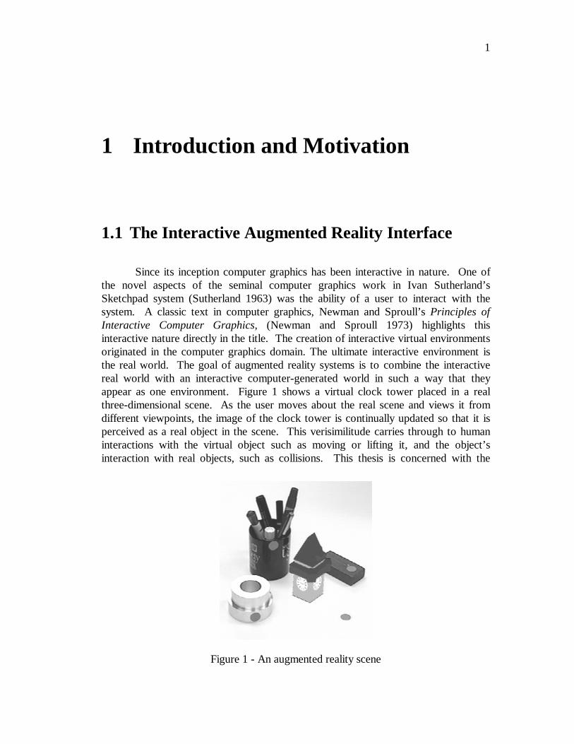
Since its inception computer graphics has been interactive in nature. One ofthe novel aspects of the seminal computer graphics work in Ivan Sutherland’sSketchpad system (Sutherland 1963) was the ability of a user to interact with thesystem. A classic text in computer graphics, Newman and Sproull’s Principles ofInteractive Computer Graphics, (Newman and Sproull 1973) highlights thisinteractive nature directly in the title. The creation of interactive virtual environmentsoriginated in the computer graphics domain. The ultimate interactive environment isthe real world. The goal of augmented reality systems is to combine the interactivereal world with an interactive computer-generated world in such a way that theyappear as one environment. Figure 1 shows a virtual clock tower placed in a realthree-dimensional scene. As the user moves about the real scene and views it fromdifferent viewpoints, the image of the clock tower is continually updated so that it isperceived as a real object in the scene. This verisimilitude carries through to humaninteractions with the virtual object such as moving or lifting it, and the object’sinteraction with real objects, such as collisions. This thesis is concerned with the
Figure 1 - An augmented reality scene
2
visual and haptic (tactile) augmented reality interface. In particular, it addresses theissues of: (1) how to generate the augmented image composed from live video andcomputer-generated images, and (2) how to use a haptic device, the 3+$17R0™, tointeract with the virtual objects.
1.2 The Major Challenges for Augmented RealitySystems
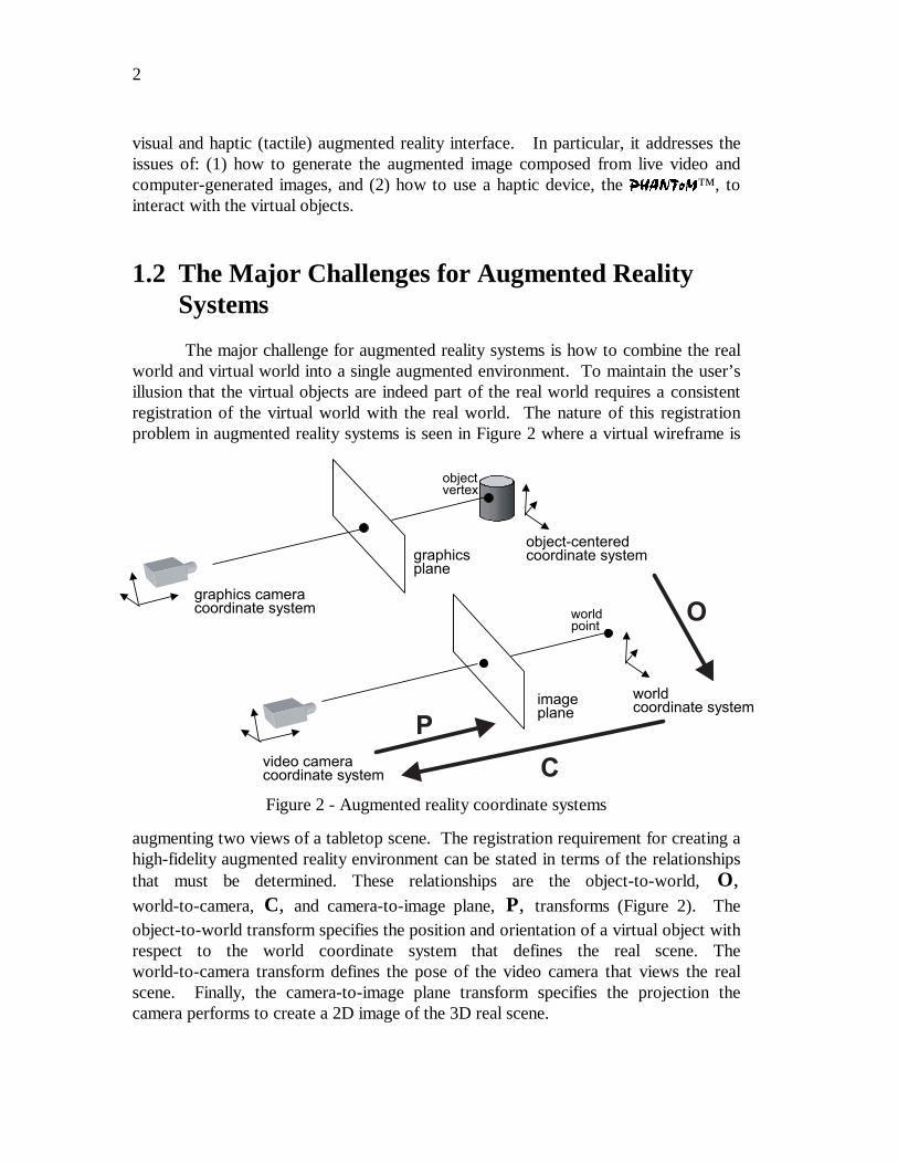
The major challenge for augmented reality systems is how to combine the realworld and virtual world into a single augmented environment. To maintain the user’sillusion that the virtual objects are indeed part of the real world requires a consistentregistration of the virtual world with the real world. The nature of this registrationproblem in augmented reality systems is seen in Figure 2 where a virtual wireframe is
augmenting two views of a tabletop scene. The registration requirement for creating ahigh-fidelity augmented reality environment can be stated in terms of the relationshipsthat must be determined. These relationships are the object-to-world, O,world-to-camera, C, and camera-to-image plane, P, transforms (Figure 2). Theobject-to-world transform specifies the position and orientation of a virtual object withrespect to the world coordinate system that defines the real scene. Theworld-to-camera transform defines the pose of the video camera that views the realscene. Finally, the camera-to-image plane transform specifies the projection thecamera performs to create a 2D image of the 3D real scene.
objectvertex
graphics cameracoordinate system
graphicsplane
object-centeredcoordinate system
video cameracoordinate system
imageplane
worldcoordinate system
worldpoint
C
O
P
Figure 2 - Augmented reality coordinate systems
3
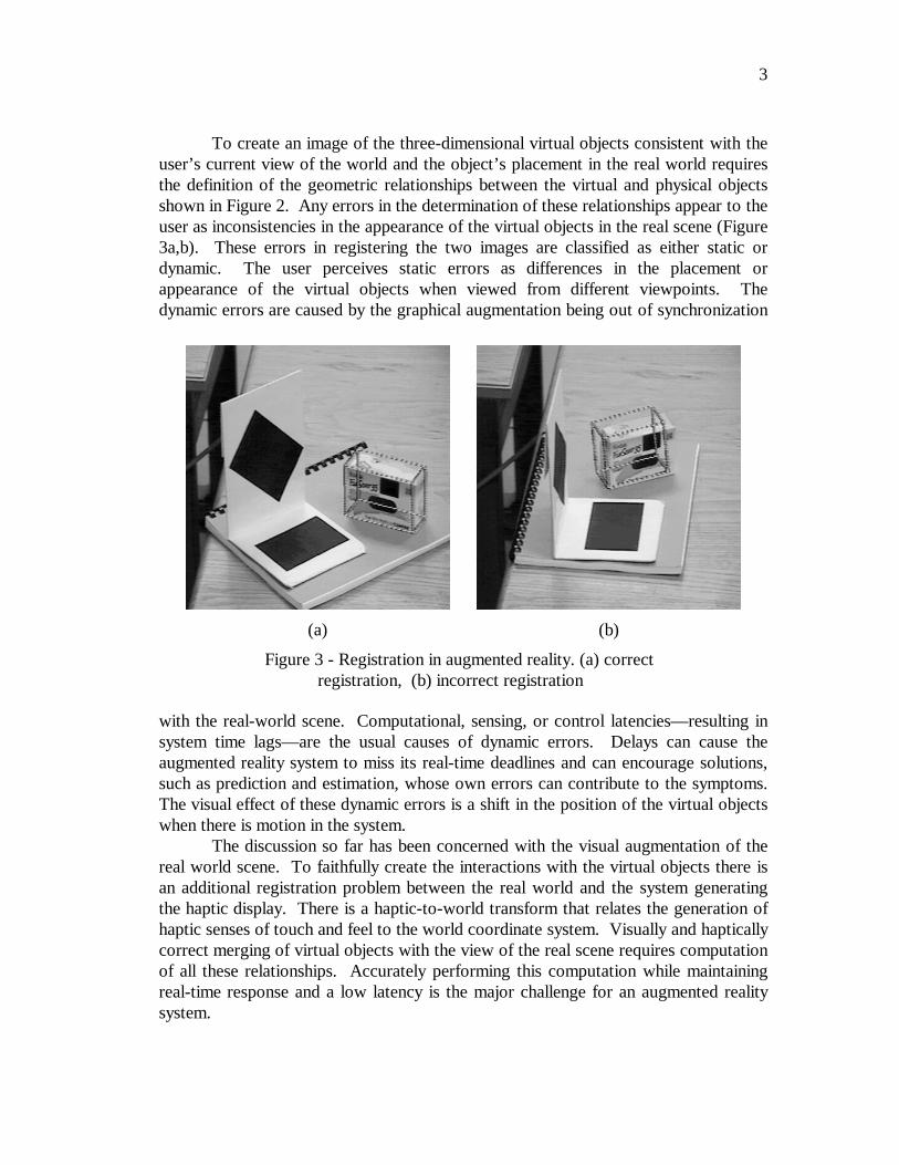
To create an image of the three-dimensional virtual objects consistent with theuser’s current view of the world and the object’s placement in the real world requiresthe definition of the geometric relationships between the virtual and physical objectsshown in Figure 2. Any errors in the determination of these relationships appear to theuser as inconsistencies in the appearance of the virtual objects in the real scene (Figure3a,b). These errors in registering the two images are classified as either static ordynamic. The user perceives static errors as differences in the placement orappearance of the virtual objects when viewed from different viewpoints. Thedynamic errors are caused by the graphical augmentation being out of synchronization
with the real-world scene. Computational, sensing, or control latencies—resulting insystem time lags—are the usual causes of dynamic errors. Delays can cause theaugmented reality system to miss its real-time deadlines and can encourage solutions,such as prediction and estimation, whose own errors can contribute to the symptoms.The visual effect of these dynamic errors is a shift in the position of the virtual objectswhen there is motion in the system.
The discussion so far has been concerned with the visual augmentation of thereal world scene. To faithfully create the interactions with the virtual objects there isan additional registration problem between the real world and the system generatingthe haptic display. There is a haptic-to-world transform that relates the generation ofhaptic senses of touch and feel to the world coordinate system. Visually and hapticallycorrect merging of virtual objects with the view of the real scene requires computationof all these relationships. Accurately performing this computation while maintainingreal-time response and a low latency is the major challenge for an augmented realitysystem.
(a) (b)
Figure 3 - Registration in augmented reality. (a) correctregistration, (b) incorrect registration
4
This thesis provides a solution for the interactive augmented reality interface.The main contributions are:
• A new method to maintain the registration between the graphic display,haptic display and view of the real world. This technique uses affinerepresentations to define a global coordinate system and unlike mostprevious augmented reality systems does not require calibration of thevideo camera viewing the scene or sensing of its position in the real scene.
• A method for the user to interact in a natural manner with the virtualobjects seen in the augmented reality display. This interaction includeshaptic sensing of the virtual objects, virtual objects exhibiting dynamic andgravitational behaviors, and interactions between virtual and real objects.
• An analysis of the static and dynamic registration error using our method ofimage registration and the effect of simple predictive filtering on dynamicerrors.
• A system architecture that allows for the real-time operation of thisinteractive augmented reality system.
The outline of this thesis is as follows. Chapter 2 develops the idea of the ideal
augmented reality system, motivating it by a large variety of current andsafely-predictable near future applications. The challenges that must be overcome toreach this ideal are difficult given the hardware and software technology that existtoday. Chapter 3 first makes explicit the current state of augmented reality hardwareand software technology and follows up with a survey on the technical aspects ofcurrent approaches for solving the problem of augmenting reality. By the end ofChapter 3 we see that current techniques have not fully achieved the requirementsspecified in Chapter 2, and we preview our extensions to previous approaches thatsupport our contributions. Chapters 4 and 5 present our contributions in detail andsuggest promising future applications and research directions. Chapter 6 provides asummary of these contributions and future opportunities.
5
2 Augmented Reality: Potential andChallenges
An augmented reality system is a system that creates a view of a real scene byincorporating computer-generated virtual objects, including those with fullthree-dimensional properties, into the scene. As the user of such a system movesabout the real scene the virtual objects appear as if they actually exist in the scene.Ideally, the virtual objects should interact with the user and real objects in the scene ina natural manner. The application domains described in Section 2.3 reveal thataugmented reality can take on a number of different forms. In all the applications thatare discussed later, augmented reality enhances the user’s performance in andperception of the world.
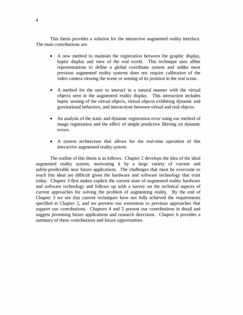
The ultimate goal is to create a system such that the user can not tell thedifference between the real world and the virtual augmentation of it. To the user ofthis ultimate system it would appear that he is working in a single real environment.Figure 4 shows a view of what the user might see while using an augmented reality
system in the medical domain. It depicts the merging and correct registration of datafrom a pre-operative imaging study onto the patient’s head. Providing this view in theoperating theater would enhance the surgeon’s performance and possibly eliminate the
Figure 4 - Medical domain example of augmented reality
6
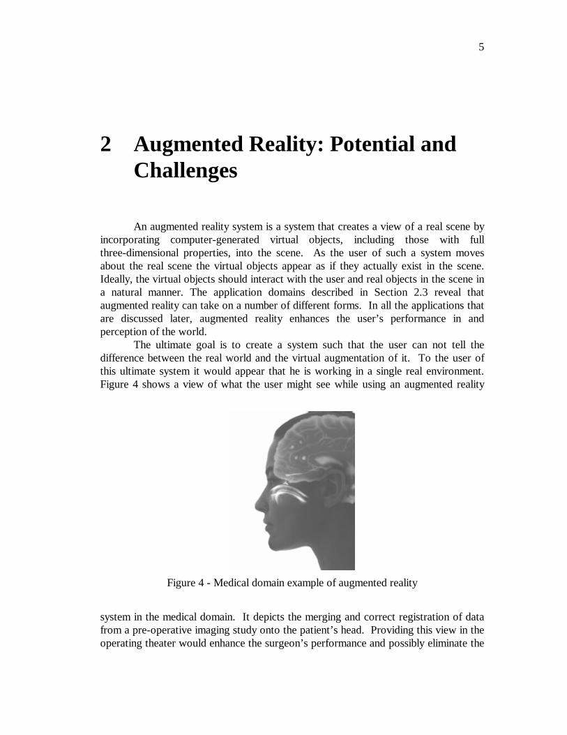
need for any other calibration fixtures during the procedure. Consider anotherapplication scenario as depicted in Figure 5. The city planners want to visualize whatthe landscape will look like when a new footbridge is built. They would go to theproposed site (Figure 5a) and (donning an augmented reality display device) see thearea with the new bridge merged into their view of the landscape (Figure 5b). Ifadjustments were needed they could be performed directly on the visual model of thenew bridge.
2.1 How Does Augmented Reality Differ from VirtualReality?
Virtual reality is a technology that encompasses a broad spectrum of ideas. Itdefines an umbrella under which many researchers and companies express their work.The phrase was originated by Jaron Lanier, the founder of VPL Research—one of theoriginal companies selling virtual reality systems. The term was defined as “acomputer-generated, interactive, three-dimensional environment in which a person isimmersed.” (Aukstakalnis and Blatner 1992). There are three key points in thisdefinition. First, this virtual environment is a computer-generated three-dimensionalscene that requires high performance computer graphics to provide an adequate levelof realism. The second point is that the virtual world is interactive. A user requiresreal-time response from the system to interact with it in an effective manner. The lastpoint is that the user is immersed in this virtual environment. One of the identifyingmarks of a virtual reality system is the head-mounted display often worn by users.These displays block out all the external world and present to the wearer a view that isunder the complete control of the computer. The user is completely immersed in an
(a) (b)
Figure 5 - Preview of a new footbridge using an augmentedreality display (Fraunhofer Institute for ComputerGraphics 1997)
7
artificial world and becomes divorced from the real environment. For this immersionto appear realistic the virtual reality system must accurately sense how the user ismoving and determine what effect that will have on the scene being rendered in thehead mounted display.
In contrast, an augmented reality system generates a composite view for theuser. The user sees an image that is the combination of the real scene being viewedand a computer-generated virtual scene. The virtual scene augments the realenvironment with additional information. There are still the requirements that as theuser moves through the workspace the effect on the computer generated world mustbe determined. Once that is done the operation of combining the virtual scene with thereal scene must be performed.
The discussion above highlights the general similarities and differences betweenvirtual reality and augmented reality systems. A very visible difference between thesetwo types of systems is the immersiveness of the system. Virtual reality strives for atotally immersive environment. The visual, and in some systems aural andproprioceptive, senses are under control of the system. This requires the virtualreality system to model its artificial world completely. Depending on the desired levelof verisimilitude, this is a very complex simulation problem. In contrast, an augmentedreality system augments the real world scene and attempts to maintain the user’s senseof being in the real world. The rationale behind this is twofold. First, realenvironments contain a wealth of information much of which is impossible to modeland simulate by computer. Secondly, if the end goal is to enhance the performance ofa real-world task, it will be performed most naturally if the user still feels immersed inthe task environment. To maintain the user’s immersion in the real world anaugmented reality system merges the virtual images with a view of the real scene tocreate the augmented display. This merging requires a mechanism to combine the realand virtual that is not present in other virtual reality work. Developing the technologyfor merging the real and virtual image streams either optically or in video is an activeresearch topic (Roland, Holloway et al. 1994) that is not addressed in this thesis. Thetechnology is briefly described in Section 3.1.1.
Requiring a means to visually merge the views of the real and virtual worlds isnot the major hurdle brought on by the inclusion of the real world in an augmentedreality system. The nature of the visual interface between computer and user isdifferent. Both virtual reality and augmented reality systems give the user a sense ofimmersion in the virtual environment by ensuring that the user receives a consistent setof sensory inputs. The primary performance goal for a virtual reality system is topresent visual stimuli that are consistent with the changes in body position sensed bythe user. This requires that motions or changes made by the user will result in theappropriate changes in the perceived virtual world. Because the user is looking at avirtual world there is no natural connection between the user’s internal proprioceptivecoordinate system and the virtual world coordinate system. A connection must beartificially created (Azuma 1993). Any inconsistency the user perceives results from amisregistration between the coordinate system the user maintains internally to describe

8
body position and the coordinate system that describes the graphics system’sviewpoint in the virtual scene. Errors are perceived here as conflicts between thevisual system and the kinesthetic or proprioceptive systems. The phenomenon ofvisual capture gives the vision system a stronger influence in our perception (Welch1978). This stronger influence allows a user of a virtual reality system to accept oradjust to the visual stimulus by overriding the discrepancies occurring with input fromthe other sensory systems.
Contrast this to the primary performance goal for an augmented reality systemwhich is to render views of virtual objects that are consistent with the user’s view ofthe real environment containing the objects. In this case, errors of misregistration arebetween two visual stimuli which we are trying to fuse to see as one scene. Theobserver is more sensitive to these errors (Azuma 1993; Azuma 1995). Anyinconsistency, which manifests itself as a difference between two visual stimuli, i.e. thevirtual and real images, derives from a misregistration between the coordinate systemdescribing the user’s viewpoint in the real scene and the graphics system’s viewpoint inthe virtual scene. This imposes a tougher registration requirement on augmentedreality systems compared to virtual reality systems.
2.2 Milgram Reality-Virtuality Continuum
Milgram (Milgram and Kishino 1994; Milgram, Takemura et al. 1994)describes a taxonomy that identifies how augmented reality and virtual reality arerelated. He defines the Reality-Virtuality continuum shown as Figure 6. The real
world and a totally virtual environment are at the two ends of this continuum with themiddle region called Mixed Reality. Augmented reality lies near the real-world end ofthe spectrum with the predominate perception being the real-world augmented bycomputer generated data. Augmented virtuality is a term created by Milgram toidentify systems that are mostly synthetic with some real world imagery added—suchas texture mapping video onto virtual objects. An example of this technology is livevideo texture-mapped onto the graphics image of an avatar—a computer-generated
5HDO(QYLURQPHQW
9LUWXDO(QYLURQPHQW
$XJPHQWHG5HDOLW\ �$5�
$XJPHQWHG9LUWXDOLW\ �$9�
0L[HG 5HDOLW\ �05�
Figure 6 - Milgram's Reality-Virtuality Continuum
9
virtual character that is a stand-in for the user’s presence within a virtual environment(Capin, Noser et al. 1997).
Milgram further defines a taxonomy for the Mixed Reality displays. The threeaxes he suggests for categorizing these systems are: Reproduction Fidelity, Extent ofPresence Metaphor and Extent of World Knowledge. Reproduction Fidelity relates tothe quality of the computer generated imagery ranging from simple wireframeapproximations to complete photorealistic renderings. The real-time constraint onaugmented reality systems forces them to be toward the low end on the ReproductionFidelity spectrum. The current graphics hardware capabilities can not produce real-time photorealistic renderings of the virtual scene. Milgram also places augmentedreality systems on the low end of the Extent of Presence Metaphor. This axismeasures the level of immersion of the user within the displayed scene. Thiscategorization is closely related to the display technology used by the system. Thereare several classes of displays used in augmented reality systems that are discussed inSection 3.1.1. Each of these gives a different sense of immersion in the virtualenvironment presented to the user. In an augmented reality system, some displaytechnologies utilize the user’s direct view of the real world. Immersion in thatenvironment comes from the user simply having his eyes open. It is contrasted tosystems where the merged view is presented to the user on a separate monitor forwhat is sometimes called a “Window on the World” (Feiner, MacIntyre et al. 1993a)view.
The third, and final, dimension that Milgram uses to categorize Mixed Realitydisplays is Extent of World Knowledge. Augmented reality does not simply mean thesuperimposition of a graphic object over a real world scene. This is technically an easytask. To do a realistic merging of virtual objects into a real scene, knowledge aboutthe world is needed. One difficulty in augmenting reality, as defined here, is the needto maintain accurate registration of the virtual objects with the real world image Thisrequires detailed knowledge of the relationship between the frames of reference for thereal world, the camera viewing it and the user as described in Section 1.2. To properlycompute the visual interactions between real and virtual objects, data about theirlocations and orientations in three-dimensional space are needed. Correct dynamicinteractions with virtual objects require knowledge of the dynamic characteristics ofboth the real and virtual objects in the augmented environment. In some domainsmodels for the real and virtual worlds are well known, which makes the task ofaugmenting reality easier or might lead the system designer to use a completely virtualenvironment.
2.3 Application Domains for Augmented Reality
Only recently have the capabilities of real-time video image processing,computer graphic systems and new display and haptic technologies converged to make
10
possible the creation of an augmented environment. In this environment, images ofthree-dimensional virtual objects are correctly registered with the view of the 3Denvironment surrounding the user and the user can interact naturally with the virtualobjects. Researchers working with augmented reality systems have proposed them assolutions in many domains. The literature discusses application areas ranging fromentertainment to military training. Many of the domains, such as medical (Rosen,Laub et al. 1996), are also considered domains for virtual reality systems. This sectionhighlights some of the proposed applications for augmented reality
2.3.1 Medical
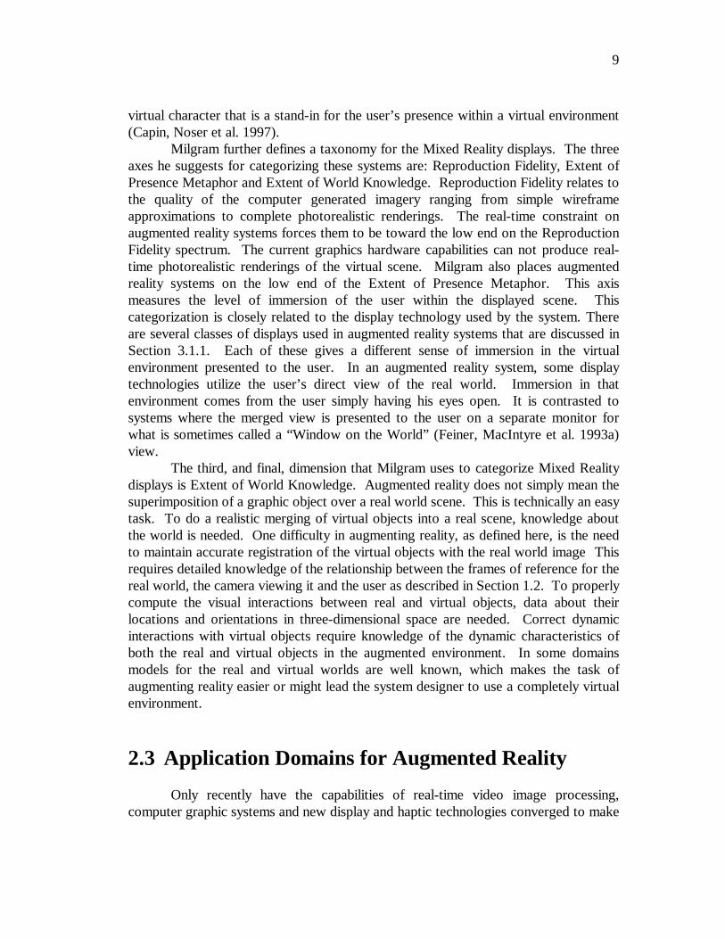
Because imaging technology is so pervasive throughout the medical field, it isnot surprising that this domain is viewed as one of the more important for augmentedreality systems. Most of the medical applications deal with image-guided surgery.Pre-operative imaging studies, such as CT or MRI scans, of the patient provide thesurgeon with the necessary view of the internal anatomy. From these images thesurgery is planned. The surgeon visualizes the path through the anatomy to theaffected area where, for example, a tumor must be removed, by first creating a 3Dmodel from the multiple views and slices in the preoperative study. Through theirextensive training, surgeons become very adept at mentally creating thethree-dimensional visualization that is needed to render a diagnosis. Some newersystems do have the ability to create 3D volume visualizations from the imaging study.Figure 7 shows how augmented reality can be applied so that the surgical team seesthe CT or MRI data correctly registered on the patient in the operating theater whilethe procedure is progressing. Being able to accurately register the images at this pointwill enhance the performance of the surgical team and may eliminate the need for thepainful and cumbersome stereotactic frames (Mellor 1995a) currently used forregistration. Descriptions of other work in the area of image-guided surgery usingaugmented reality can be found in (Lorensen, Cline et al. 1993; Grimson, Lozano-
Figure 7 - Image guided surgical procedure (Ettinger, Grimsonet al. 1998)
11
Perez et al. 1994; Betting, Feldmar et al. 1995; Grimson, Ettinger et al. 1995; Mellor1995a; Uenohara and Kanade 1995; Jannin, Bouliou et al. 1997).
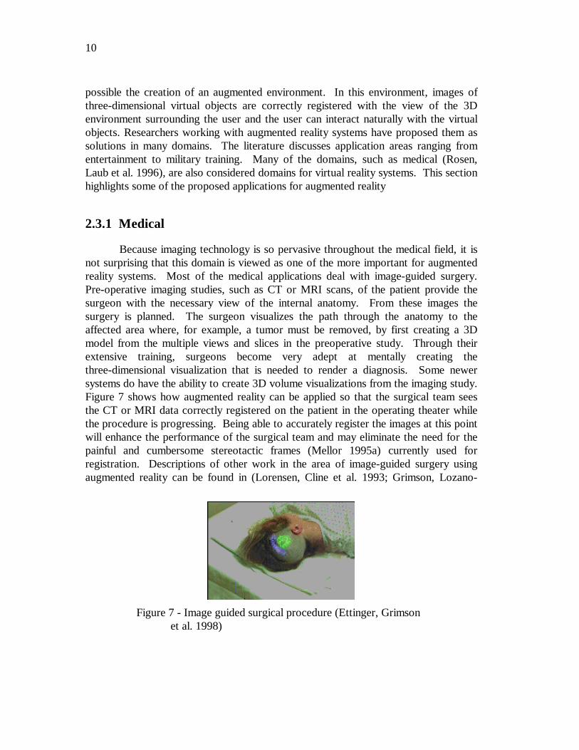
Another application for augmented reality in the medical domain is inultrasound imaging (State, Chen et al. 1994). Using an optical see-through display(Section 3.1.1) the physician can view a volumetric rendered image of the fetusoverlaid on the abdomen of the pregnant woman. The image appears as if it wereinside the abdomen and is correctly rendered as the user moves. Figure 8a shows animage from the system along with a second application in ultrasound imaging seen inFigure 8b. In this second application, the augmented reality image helps the surgeonguide a biopsy needle to the site of a suspected tumor during a mock breast biopsyprocedure. The V-shaped object in the left part of the image is used for registering theultrasound image with the view of the real scene that the surgeon is seeing.
Finally, a future application is the extension of the virtual reality basedcraniofacial surgery visualization and simulation systems (Patel, Vannier et al. 1996;Taylor, Funda et al. 1996) by adding an augmented reality display. These systemscurrently allow the surgeon to experiment, within the safety of a virtual environment,with different treatment approaches for the reconstructive work to be done. Themodel that the surgeon works on is a 3D volume visualization derived from apre-operative CT or MR study. Augmented reality would allow the surgeon to see thefinal results directly on the patient rather than only with the volume visualization.
2.3.2 Entertainment
A simple form of augmented reality has been in use in the entertainment andnews business for quite some time. When you watch an evening weather report theweather reporter often stands in front of changing weather maps. In the studio the
(a) (b)
Figure 8 - Ultrasound imaging using augmented reality displays(a (UNC - Chapel Hill 1995); b (UNC - Chapel Hill1997))
12
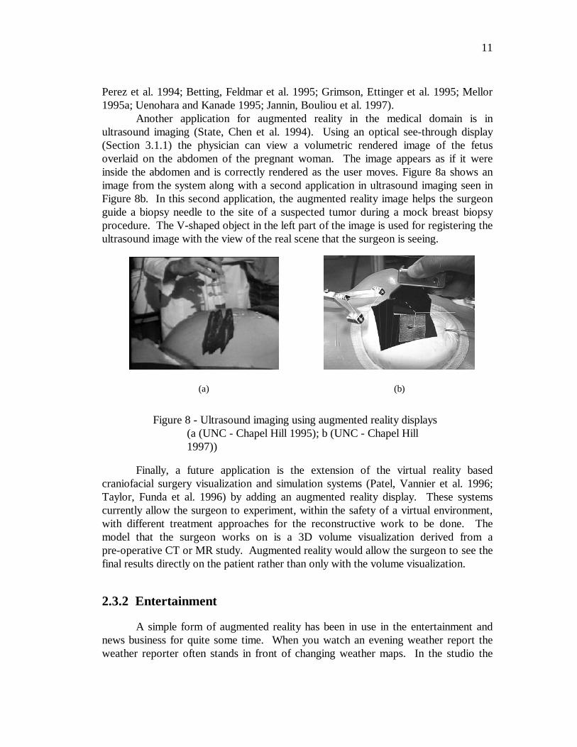
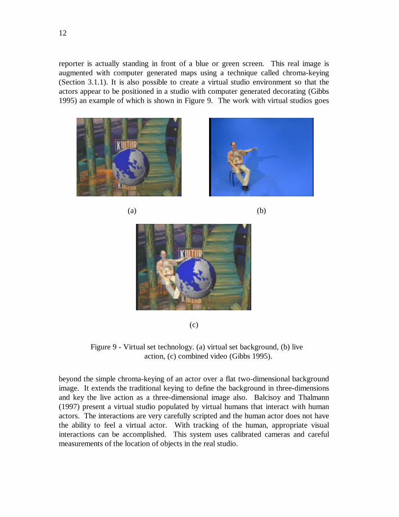
reporter is actually standing in front of a blue or green screen. This real image isaugmented with computer generated maps using a technique called chroma-keying(Section 3.1.1). It is also possible to create a virtual studio environment so that theactors appear to be positioned in a studio with computer generated decorating (Gibbs1995) an example of which is shown in Figure 9. The work with virtual studios goes
beyond the simple chroma-keying of an actor over a flat two-dimensional backgroundimage. It extends the traditional keying to define the background in three-dimensionsand key the live action as a three-dimensional image also. Balcisoy and Thalmann(1997) present a virtual studio populated by virtual humans that interact with humanactors. The interactions are very carefully scripted and the human actor does not havethe ability to feel a virtual actor. With tracking of the human, appropriate visualinteractions can be accomplished. This system uses calibrated cameras and carefulmeasurements of the location of objects in the real studio.
(a) (b)
(c)
Figure 9 - Virtual set technology. (a) virtual set background, (b) liveaction, (c) combined video (Gibbs 1995).
13
Movie special effects make use of digital compositing to create illusions (Pyrosand Goren 1995). Strictly speaking, with current technology, this is not consideredaugmented reality because it is not generated in real-time. Most special effects arecreated off-line, frame by frame with a substantial amount of user interaction andcomputer graphics system rendering. But some work is progressing in computeranalysis of the live action images to determine the camera parameters and use this todrive the generation of the virtual graphics objects to be merged (Zorpette 1994).
Princeton Electronic Billboard has developed an augmented reality system thatallows broadcasters to insert advertisements into specific areas of the broadcast(National Association of Broadcasters 1994). For example, while broadcasting abaseball game this system places an advertisement in the image so that it appears onthe outfield wall of the stadium. The electronic billboard requires calibration to thestadium by taking images from typical camera angles and zoom settings in order tobuild a map of the stadium including the locations in the images where advertisementswill be inserted. By using pre-specified reference points in the stadium, the systemautomatically determines the camera angle being used and referring to the pre-definedstadium map inserts the advertisement into the correct place. The approach used formapping these planar surfaces is similar to that which is presented in Chapter 4 of thisthesis. A French company, Symah Vision, has also developed a similar application.Another application in sports broadcasting is Fox network’s FoxTrax system(Cavallaro 1997) for tracking the path of a hockey puck during a game. The path ofthe puck is overlaid on the image of the hockey rink as a blue streak. The streakchanged color based on the speed of the puck. This system requires a detailedcalibration process for each television camera and the ice ring itself.
Augmented reality can be applied to enhance games that people play. Asystem (Jebara, Eyster et al. 1997) developed for pocket billiards players uses ahead-mounted display and wearable computer to analyze the layout of the table andsuggest possible shots for the player to take. The trajectory of the shot is displayed asaugmented graphics over the image of the pool table. Or consider a futuristic game ofpaintball where players wear augmented reality headsets. The image that the playerssee is not only of the game area and their real opponents but virtual players are alsoplaying along with them.
2.3.3 Military
The military has been using displays in cockpits that present information to thepilot on the windshield of the cockpit or the visor of their flight helmet. This is a formof augmented reality display. SIMNET, a distributed war games simulation system, isalso embracing augmented reality technology. By equipping military personnel withhelmet mounted visor displays or a special purpose rangefinder (Urban 1995) theactivities of other units participating in the exercise are seen. While looking at thehorizon, for example, the display-equipped soldier sees a helicopter rising above the
14
tree line (Metzger 1993). Actually, another participant is flying this helicopter insimulation. In wartime, the display of the real battlefield scene could be augmentedwith annotation information or highlighting to emphasize hidden enemy units.
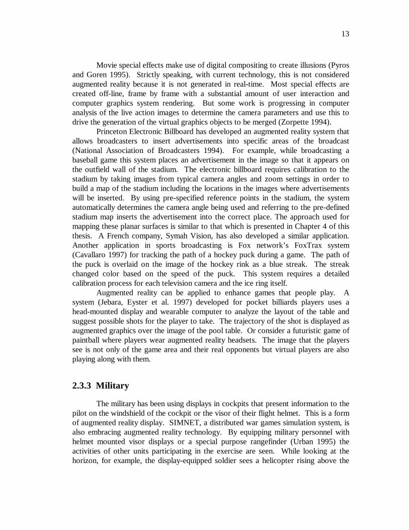
The University of Rochester is participating in the Video Surveillance andMonitoring (VSAM) project funded by the Defense Advance Research ProjectsAgency (DARPA). Figure 10 shows the scenario for using augmented reality in thisproject. Aerial reconnaissance units fly overhead and generate reference marks for
registration. Autonomous ground units with video surveillance equipment monitorsections of the same area. Aerial views augmented by the information from thesurveillance units are generated for strategic command and control. Another scenarioequips ground level warfighter or urban crime/terrorist fighters with special displays.Aerial reconnaissance units identify suspect objects and transmit the location of theseobjects to the ground units. The suspect objects may be hidden from the view of theground forces but will appear in the augmented view on their displays.
Figure 10 - Video Surveillance and Monitoring (VSAM) scenario
15
2.3.4 Engineering Design
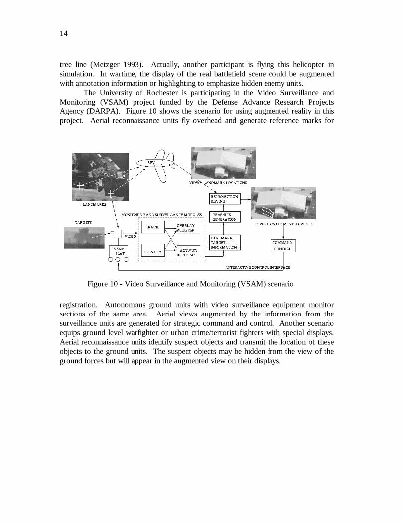
Imagine that a group of designers is working on the model of a complex devicefor their clients. The designers and clients want to do a joint design review eventhough they are physically separated. If each of them had a conference room that wasequipped with an augmented reality display this could be accomplished. The physicalprototype that the designers have mocked up is imaged and displayed in the client’sconference room in 3D. The clients walk around the display looking at differentaspects of it. To hold discussions the client points at the prototype to highlightsections and this is reflected on the real model in the augmented display that thedesigners are using (Figure 11). Or perhaps in an earlier stage of the design, before aprototype is built, the view in each conference room is augmented with a computergenerated image of the current design built from the CAD files describing it. Thisallows real time interaction with elements of the design so that either side can makeadjustments and changes that are reflected in the view seen by both groups (Ahlers,
Kramer et al. 1995). A technique for interactively obtaining a model for 3D objectscalled 3D stenciling that takes advantage of an augmented reality display is beinginvestigated in our department by Kyros Kutulakos (Kutulakos and Vallino 1996a).
Figure 11 - Engineering design using an augmented reality display(Breen 1995)
16
2.3.5 Robotics and Telerobotics
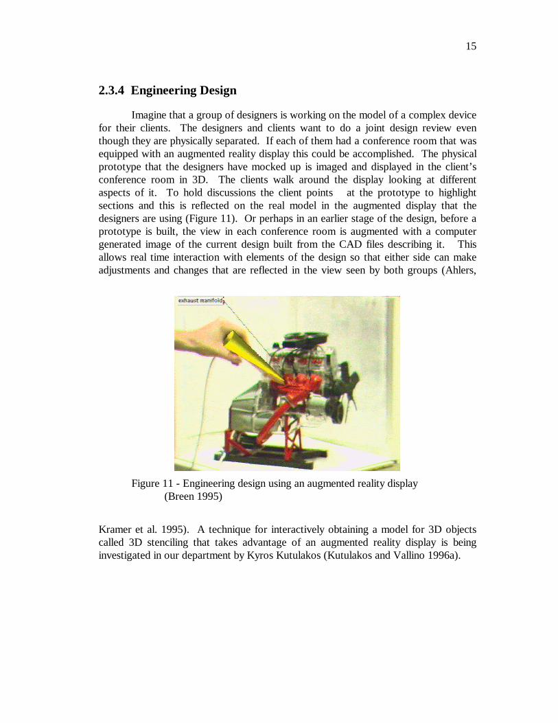
In the domain of robotics and telerobotics an augmented display can assist theuser of the system (Kim, Schenker et al. 1993; Milgram, Zhai et al. 1993). Croby andNafis (1994) describe an augmented reality telemanipulation system for nuclear reactorinspection operations. In a telerobotic system, the operator uses a visual image of theremote workspace to guide the robot. Annotation of the view would still be usefuljust as it is when the scene is in front of the operator. There is an added potentialbenefit. Since often the view of the remote scene is monoscopic, augmentation withwireframe drawings of structures in the view facilitates visualization of the remote 3Dgeometry. If the operator is attempting a motion he first practices it on a virtual robotthat he sees as an augmentation to the real scene (Figure 12). The operator can decideto proceed with the motion after seeing the results. The robot executes the motionpattern directly which in a telerobotics application eliminates the oscillations oftenpresent due to long communication delays to the remote site.
Figure 12 - Augmented reality in robotics (Rastogi, Milgram et al.1995)
17
2.3.6 Manufacturing, Maintenance and Repair
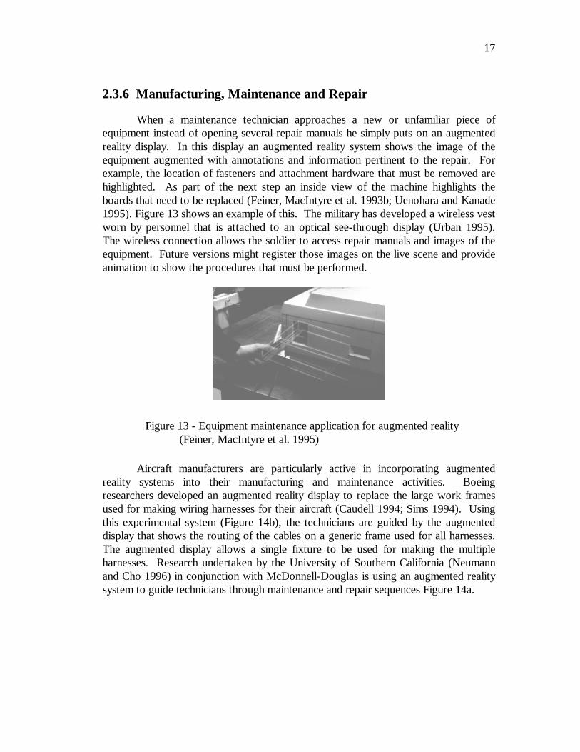
When a maintenance technician approaches a new or unfamiliar piece ofequipment instead of opening several repair manuals he simply puts on an augmentedreality display. In this display an augmented reality system shows the image of theequipment augmented with annotations and information pertinent to the repair. Forexample, the location of fasteners and attachment hardware that must be removed arehighlighted. As part of the next step an inside view of the machine highlights theboards that need to be replaced (Feiner, MacIntyre et al. 1993b; Uenohara and Kanade1995). Figure 13 shows an example of this. The military has developed a wireless vestworn by personnel that is attached to an optical see-through display (Urban 1995).The wireless connection allows the soldier to access repair manuals and images of theequipment. Future versions might register those images on the live scene and provideanimation to show the procedures that must be performed.
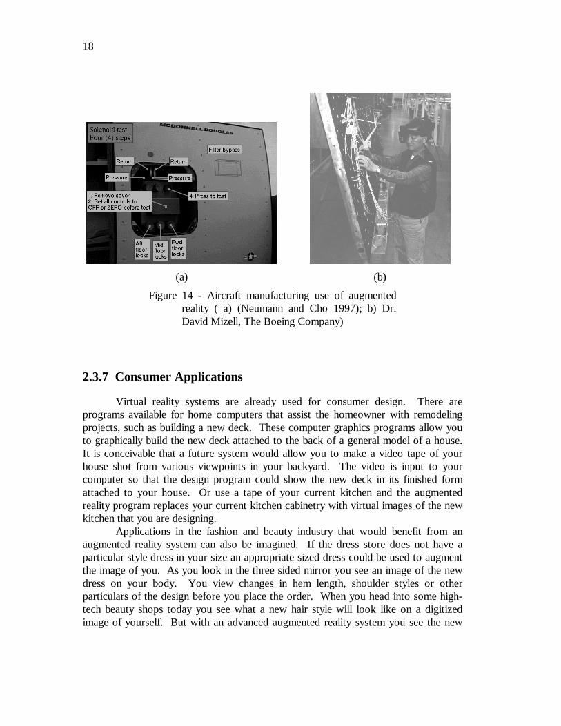
Aircraft manufacturers are particularly active in incorporating augmentedreality systems into their manufacturing and maintenance activities. Boeingresearchers developed an augmented reality display to replace the large work framesused for making wiring harnesses for their aircraft (Caudell 1994; Sims 1994). Usingthis experimental system (Figure 14b), the technicians are guided by the augmenteddisplay that shows the routing of the cables on a generic frame used for all harnesses.The augmented display allows a single fixture to be used for making the multipleharnesses. Research undertaken by the University of Southern California (Neumannand Cho 1996) in conjunction with McDonnell-Douglas is using an augmented realitysystem to guide technicians through maintenance and repair sequences Figure 14a.
Figure 13 - Equipment maintenance application for augmented reality(Feiner, MacIntyre et al. 1995)
18
2.3.7 Consumer Applications
Virtual reality systems are already used for consumer design. There areprograms available for home computers that assist the homeowner with remodelingprojects, such as building a new deck. These computer graphics programs allow youto graphically build the new deck attached to the back of a general model of a house.It is conceivable that a future system would allow you to make a video tape of yourhouse shot from various viewpoints in your backyard. The video is input to yourcomputer so that the design program could show the new deck in its finished formattached to your house. Or use a tape of your current kitchen and the augmentedreality program replaces your current kitchen cabinetry with virtual images of the newkitchen that you are designing.
Applications in the fashion and beauty industry that would benefit from anaugmented reality system can also be imagined. If the dress store does not have aparticular style dress in your size an appropriate sized dress could be used to augmentthe image of you. As you look in the three sided mirror you see an image of the newdress on your body. You view changes in hem length, shoulder styles or otherparticulars of the design before you place the order. When you head into some high-tech beauty shops today you see what a new hair style will look like on a digitizedimage of yourself. But with an advanced augmented reality system you see the new
(a) (b)
Figure 14 - Aircraft manufacturing use of augmentedreality ( a) (Neumann and Cho 1997); b) Dr.David Mizell, The Boeing Company)
19
styling as you move. If the dynamics of hair are included in the description of thevirtual object you also see the motion of your hair as your head moves.
2.4 Performance Goals
The application domains and projects described so far in this chapter motivatethe desire to develop interactive augmented reality systems. These current and futureapplications help to shape the requirements specification for an interactive augmentedreality system. Consider the requirements specified in this section to be the idealrequirements. It is against these requirements that the reader will compare theachievements of the previous approaches to augmenting reality (Chapter 3) and theapproach put forward by this thesis (Chapter 4). These comparisons should betempered somewhat by the particular application under consideration. Someapplications will not demand an “ultimate” augmented reality system.
An augmented reality system with a high degree of verisimilitude and utilitywill possess the following ideal characteristics:
• Constrained cost to allow for broader usage. To allow augmented realitysystems to be deployed in a wide range of applications the cost for thesystem should be constrained. This leads to a goal of using inexpensiveconsumer grade video cameras, personal computer processing and lowerresolution display technology.
• Perfect static registration of virtual objects in the augmented view. Whena virtual object has been placed at a location in the real scene it shouldappear to the user to remain at that same position in 3D space unless anobject has interacted with it. If the system can not meet this goal for allstatic viewpoints, it will not be possible to met the following more difficultdynamic registration requirement.
• Perfect dynamic registration of virtual objects in the augmented view.Visual updates should be performed at a rate of, at least 15 Hz, andpreferably, 30 Hz. Perhaps more importantly, latencies should beminimized. If changes in the rendering of the virtual objects lag behind theuser action triggering them the virtual objects will appear to “swim” aroundin three-dimensional space.
• Perfect registration of visual and haptic scenes. This can be phrased asWYSIWYF or “What you see is what you feel.” The visual image of avirtual object should match with its haptic counterpart. The user should
20
feel the surface of a virtual object at the same time and in the same placethat the augmented view shows the contact.
• Virtual and real objects are visually indistinguishable. In addition tophotorealistic rendering of the virtual objects—the usual consideration forcomputer graphics applications—there are additional requirements specificto interactive augmented reality applications. Visual occlusions betweenvirtual and real objects must occur correctly. This is not only for virtualobjects occluding real ones, but also for the more difficult case of realobjects occluding virtual ones. Lighting in the augmented view must bematched between the real and virtual worlds.
• Virtual objects exhibit standard dynamic behavior. When the userinteracts with a virtual object it should move with the same dynamicbehavior that an equivalent real object would exhibit. This includescorrectly rebounding from collisions between virtual objects or betweenvirtual and real objects. To accommodate this characteristic, the system’sinternal representation of objects should help to compute the graphicsrendering of virtual objects and the interactions and dynamics of all objects.
• The user has unconstrained motion within the workspace. The systemshould allow movement without constraints or limitations. It would beideal to have no mechanical limitations, blind spots or motion constraints.
• Minimal apriori calibration or run-time setup is required. To determinethe location of the viewer many augmented reality systems requirecalibration of the video camera viewing the scene. This calibration processis tedious to perform and will often limit operation to a single focal length.Lenses on standard consumer grade video cameras can not be zoomed in orout because they do not provide feedback of zoom position. Duringstart-up of the system the user should not have to perform extensive setupsuch as measurement of the locations of fiducials, or complicatedprocedures for placing objects into the scene.
To date, no augmented reality system, including the one developed as part ofthis thesis work, has met all of the performance goals for the ideal system. Comparingthese goals against the capabilities of the previous approaches to augmenting realitydescribed in Chapter 3 and the approach using affine representations presented by thisthesis (Chapter 4) the reader can determine how close the state-of-the-art comes toachieving all of the performance goals for the ultimate interactive augmented realitysystem.
21
3 Augmented Reality: Technology andPractice
This chapter describes the technology and practice of augmented realitysystems. There is some unique technology involved upon which augmented realitysystems are built. The first section of this chapter discusses the display and haptictechnology that is available for use in an interactive augmented reality system. Thechapter continues with a discussion of the previous practice for realizing an augmentedreality interface by, first, presenting a simple taxonomy for the methods used toregister the real and virtual images. A review of the prior research in registering thevirtual and real images follows. The chapter concludes with a discussion of the smallamount of haptic work associated with augmented reality interfaces.
3.1 System Components
A system that creates an augmented reality interface is a tightly connected setof components operating in real time. This section describes the components ofaugmented reality systems and highlights the state-of-the-art technology that isavailable for their implementation specifically in the areas of display and haptictechnology.
3.1.1 Augmented reality display technology
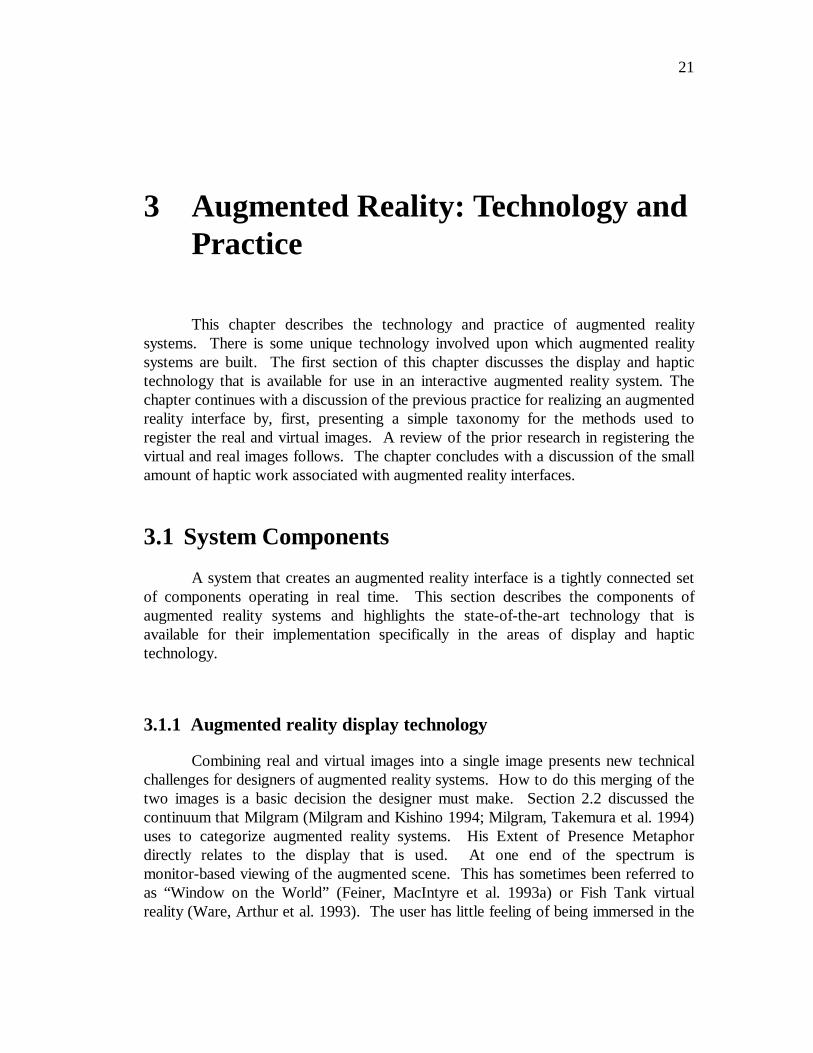
Combining real and virtual images into a single image presents new technicalchallenges for designers of augmented reality systems. How to do this merging of thetwo images is a basic decision the designer must make. Section 2.2 discussed thecontinuum that Milgram (Milgram and Kishino 1994; Milgram, Takemura et al. 1994)uses to categorize augmented reality systems. His Extent of Presence Metaphordirectly relates to the display that is used. At one end of the spectrum ismonitor-based viewing of the augmented scene. This has sometimes been referred toas “Window on the World” (Feiner, MacIntyre et al. 1993a) or Fish Tank virtualreality (Ware, Arthur et al. 1993). The user has little feeling of being immersed in the
22
environment created by the display. This technology, diagrammed in Figure 15, is thesimplest available. It is the primary technology that the work in this thesis uses as doseveral other systems in the literature (Drascic, Grodski et al. 1993; Ahlers, Breen etal. 1994).
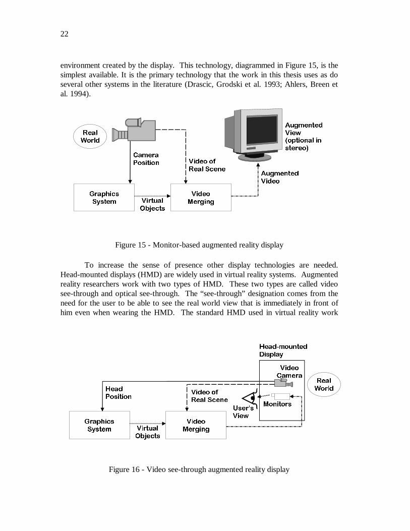
To increase the sense of presence other display technologies are needed.Head-mounted displays (HMD) are widely used in virtual reality systems. Augmentedreality researchers work with two types of HMD. These two types are called videosee-through and optical see-through. The “see-through” designation comes from theneed for the user to be able to see the real world view that is immediately in front ofhim even when wearing the HMD. The standard HMD used in virtual reality work
$XJPHQWHG9LHZ
&DPHUD3RVLWLRQ 9LGHR RI
5HDO 6FHQH
9LGHR
0HUJLQJ
*UDSKLFV6\VWHP 9LUWXDO
2EMHFWV
$XJPHQWHG9LGHR
�RSWLRQDO LQVWHUHR�
5HDO:RUOG
Figure 15 - Monitor-based augmented reality display
+HDG3RVLWLRQ
9LGHR RI5HDO 6FHQH
9LGHR0HUJLQJ
*UDSKLFV6\VWHP 9LUWXDO
2EMHFWV
5HDO:RUOG
0RQLWRUV
9LGHR&DPHUD
+HDG�PRXQWHG'LVSOD\
8VHUV9LHZ
Figure 16 - Video see-through augmented reality display
23
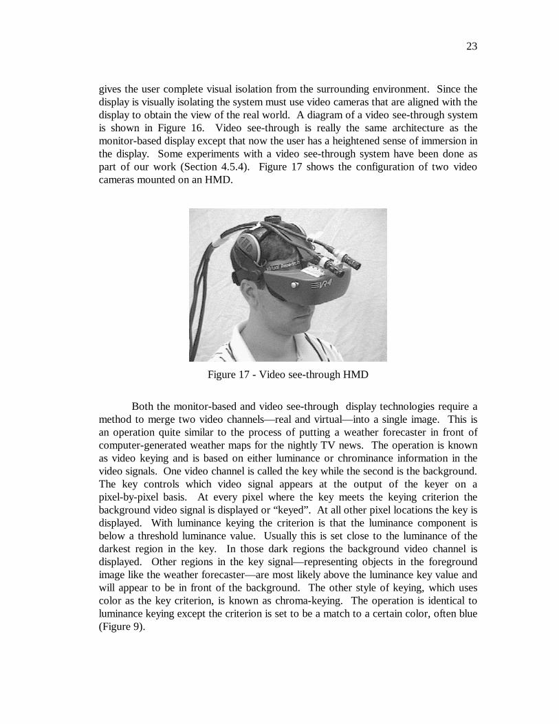
gives the user complete visual isolation from the surrounding environment. Since thedisplay is visually isolating the system must use video cameras that are aligned with thedisplay to obtain the view of the real world. A diagram of a video see-through systemis shown in Figure 16. Video see-through is really the same architecture as themonitor-based display except that now the user has a heightened sense of immersion inthe display. Some experiments with a video see-through system have been done aspart of our work (Section 4.5.4). Figure 17 shows the configuration of two videocameras mounted on an HMD.
Both the monitor-based and video see-through display technologies require amethod to merge two video channels—real and virtual—into a single image. This isan operation quite similar to the process of putting a weather forecaster in front ofcomputer-generated weather maps for the nightly TV news. The operation is knownas video keying and is based on either luminance or chrominance information in thevideo signals. One video channel is called the key while the second is the background.The key controls which video signal appears at the output of the keyer on apixel-by-pixel basis. At every pixel where the key meets the keying criterion thebackground video signal is displayed or “keyed”. At all other pixel locations the key isdisplayed. With luminance keying the criterion is that the luminance component isbelow a threshold luminance value. Usually this is set close to the luminance of thedarkest region in the key. In those dark regions the background video channel isdisplayed. Other regions in the key signal—representing objects in the foregroundimage like the weather forecaster—are most likely above the luminance key value andwill appear to be in front of the background. The other style of keying, which usescolor as the key criterion, is known as chroma-keying. The operation is identical toluminance keying except the criterion is set to be a match to a certain color, often blue(Figure 9).
Figure 17 - Video see-through HMD
24
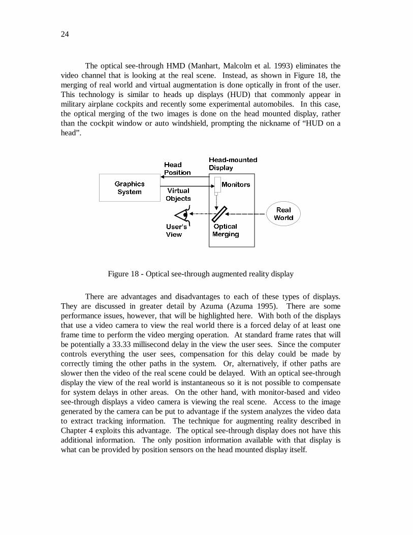
The optical see-through HMD (Manhart, Malcolm et al. 1993) eliminates thevideo channel that is looking at the real scene. Instead, as shown in Figure 18, themerging of real world and virtual augmentation is done optically in front of the user.This technology is similar to heads up displays (HUD) that commonly appear inmilitary airplane cockpits and recently some experimental automobiles. In this case,the optical merging of the two images is done on the head mounted display, ratherthan the cockpit window or auto windshield, prompting the nickname of “HUD on ahead”.
There are advantages and disadvantages to each of these types of displays.They are discussed in greater detail by Azuma (Azuma 1995). There are someperformance issues, however, that will be highlighted here. With both of the displaysthat use a video camera to view the real world there is a forced delay of at least oneframe time to perform the video merging operation. At standard frame rates that willbe potentially a 33.33 millisecond delay in the view the user sees. Since the computercontrols everything the user sees, compensation for this delay could be made bycorrectly timing the other paths in the system. Or, alternatively, if other paths areslower then the video of the real scene could be delayed. With an optical see-throughdisplay the view of the real world is instantaneous so it is not possible to compensatefor system delays in other areas. On the other hand, with monitor-based and videosee-through displays a video camera is viewing the real scene. Access to the imagegenerated by the camera can be put to advantage if the system analyzes the video datato extract tracking information. The technique for augmenting reality described inChapter 4 exploits this advantage. The optical see-through display does not have thisadditional information. The only position information available with that display iswhat can be provided by position sensors on the head mounted display itself.
+HDG�PRXQWHG'LVSOD\
5HDO:RUOG
2SWLFDO0HUJLQJ
0RQLWRUV*UDSKLFV
6\VWHP 9LUWXDO2EMHFWV
+HDG3RVLWLRQ
8VHUV9LHZ
Figure 18 - Optical see-through augmented reality display
25
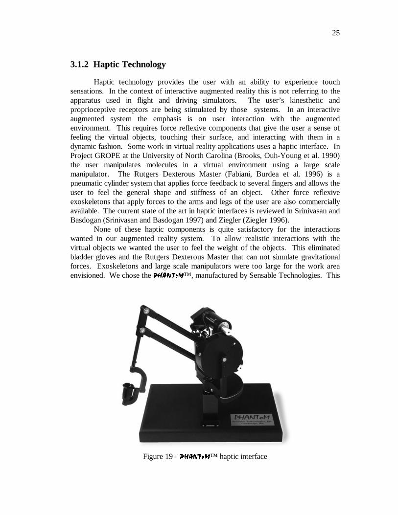
3.1.2 Haptic Technology
Haptic technology provides the user with an ability to experience touchsensations. In the context of interactive augmented reality this is not referring to theapparatus used in flight and driving simulators. The user’s kinesthetic andproprioceptive receptors are being stimulated by those systems. In an interactiveaugmented system the emphasis is on user interaction with the augmentedenvironment. This requires force reflexive components that give the user a sense offeeling the virtual objects, touching their surface, and interacting with them in adynamic fashion. Some work in virtual reality applications uses a haptic interface. InProject GROPE at the University of North Carolina (Brooks, Ouh-Young et al. 1990)the user manipulates molecules in a virtual environment using a large scalemanipulator. The Rutgers Dexterous Master (Fabiani, Burdea et al. 1996) is apneumatic cylinder system that applies force feedback to several fingers and allows theuser to feel the general shape and stiffness of an object. Other force reflexiveexoskeletons that apply forces to the arms and legs of the user are also commerciallyavailable. The current state of the art in haptic interfaces is reviewed in Srinivasan andBasdogan (Srinivasan and Basdogan 1997) and Ziegler (Ziegler 1996).
None of these haptic components is quite satisfactory for the interactionswanted in our augmented reality system. To allow realistic interactions with thevirtual objects we wanted the user to feel the weight of the objects. This eliminatedbladder gloves and the Rutgers Dexterous Master that can not simulate gravitationalforces. Exoskeletons and large scale manipulators were too large for the work areaenvisioned. We chose the 3+$17R0™, manufactured by Sensable Technologies. This
Figure 19 - 3+$17R0™ haptic interface
26
device, shown in Figure 19, looks like a miniature robot arm. In many ways it is.Each joint is driven by a small motor and the controller coordinates the motoroperation to generate force feedback at the end effector. The standard end effector isa thimble into which the user inserts a finger. With the supplied GHOST library thesystem can define a world of objects that create the haptic scene to be rendered. ThePhantom gives the user a very compelling sense of touching these virtual objects.Mass can be assigned to the objects so if the user places his finger under an object andlifts, the weight of the object is felt resting on the finger. It is also possible to simulatecharacteristics such as object surface compliance and texture.
Haptic simulation comes with a high computational load requirement (Mark,Randolph et al. 1996). To provide a veridical sensation, the Phantom low-levelprocessing servo loop requires servicing at a 1 kHz rate. This places a highcomputational load on the processor supporting this haptic device. We use thesmallest device available. It has 3 degree of freedom force feedback and supports therange of motion approximate to hand movement pivoting at the user’s wrist. SensableTechnologies also manufactures larger sized devices and the uninstrumented standardend tool can be replaced with an instrumented stylus tool. This last item provides dataabout the orientation of the user’s grasp at the active end of the Phantom.
3.2 A Taxonomy for Registering the Real and VirtualImages
The primary challenge for an augmented reality system is to determine therelationship between the multiple coordinate systems shown in Figure 2. Only whenthese relationships are known can the images of the virtual objects and the view of thereal scene be correctly registered for merging as a single image. Most of the previouswork has approached this problem in a straightforward manner using position sensingto obtain the location and orientation of the viewer or the camera viewing the scene.This combined with information about the calibration parameters of the cameracompletely defines the relationships between coordinate systems.
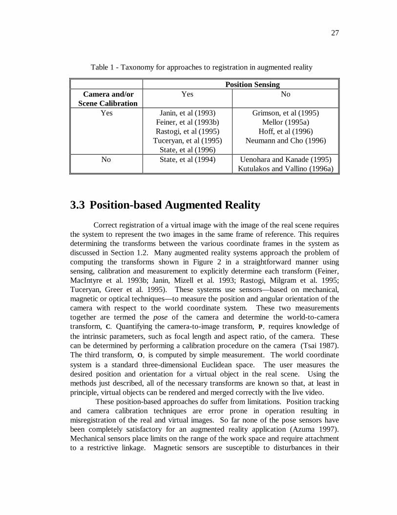
We classify previous approaches in a taxonomy according to their usage ofposition sensing and camera or scene calibration. Table 1 shows this taxonomy.Methods using position sensing typically measure the location of the viewer and/orcamera viewing the scene with a sensor. The Polhemus magnetic sensor (PolhemusCorporation 1996) is typical. The other axis in Table 1 classifies methods based onwhether they require the intrinsic parameters of the camera viewing the scene orknowledge of the metric location of features in the real scene. The intrinsic cameraparameters might include lens focal length, and the height and width of the pixelsensor. The scene calibration is usually the location of fiducial points in the threedimensional real scene. The system detects the fiducials in the image at runtime andfrom their position computes the location of the viewer.
27
3.3 Position-based Augmented Reality
Correct registration of a virtual image with the image of the real scene requiresthe system to represent the two images in the same frame of reference. This requiresdetermining the transforms between the various coordinate frames in the system asdiscussed in Section 1.2. Many augmented reality systems approach the problem ofcomputing the transforms shown in Figure 2 in a straightforward manner usingsensing, calibration and measurement to explicitly determine each transform (Feiner,MacIntyre et al. 1993b; Janin, Mizell et al. 1993; Rastogi, Milgram et al. 1995;Tuceryan, Greer et al. 1995). These systems use sensors—based on mechanical,magnetic or optical techniques—to measure the position and angular orientation of thecamera with respect to the world coordinate system. These two measurementstogether are termed the pose of the camera and determine the world-to-cameratransform, C. Quantifying the camera-to-image transform, P, requires knowledge ofthe intrinsic parameters, such as focal length and aspect ratio, of the camera. Thesecan be determined by performing a calibration procedure on the camera (Tsai 1987).The third transform, O, is computed by simple measurement. The world coordinatesystem is a standard three-dimensional Euclidean space. The user measures thedesired position and orientation for a virtual object in the real scene. Using themethods just described, all of the necessary transforms are known so that, at least inprinciple, virtual objects can be rendered and merged correctly with the live video.
These position-based approaches do suffer from limitations. Position trackingand camera calibration techniques are error prone in operation resulting inmisregistration of the real and virtual images. So far none of the pose sensors havebeen completely satisfactory for an augmented reality application (Azuma 1997).Mechanical sensors place limits on the range of the work space and require attachmentto a restrictive linkage. Magnetic sensors are susceptible to disturbances in their
Table 1 - Taxonomy for approaches to registration in augmented reality
Position SensingCamera and/or
Scene CalibrationYes No
Yes Janin, et al (1993)Feiner, et al (1993b)Rastogi, et al (1995)
Tuceryan, et al (1995)State, et al (1996)
Grimson, et al (1995)Mellor (1995a)
Hoff, et al (1996)Neumann and Cho (1996)
No State, et al (1994) Uenohara and Kanade (1995)Kutulakos and Vallino (1996a)
28
generated magnetic field created by metal objects in the workspace. Calibration forthese distortions can reduce the errors (Byrson 1992). The magnetic sensors also havelatencies that can only be improved with predictive estimation of pose (Azuma andBishop 1994) Techniques for calibrating a camera to determine its intrinsic parametersare available (Tsai 1987) but it is a tedious process to perform. The intrinsicparameters of a camera may change over time, requiring recalibration. In particular,zoom lenses, like those found on common consumer-grade video cameras, may changefocal length either by being intentionally zoomed or because of wear through use.Accurate sensing of zoom setting is not available, so recalibration is required aftereach change in focal length. If cost containment is not a concern then instrumentedzoom lenses can be used, but they require precalibration of the lens at each zoomsetting (and possibly occasional recalibration). Any errors introduced by incorrectpose sensing or camera calibration propagate through the system and appear asmisregistration in the final augmented reality image.
One position-based reference in Table 1 does not require camera or scenecalibration. State, Chen, et. al. (1994) describe the ultrasound visualization systemwhose operation is shown in Figure 8a. Their system uses Polhemus sensors formeasuring the position of the ultrasound imaging wand and the user’s position andorientation while wearing an optical see-through display system. These measurementsare both in the same coordinate system and thus directly provide the relationshipbetween them. There is no camera, per se, in the system so calibration is not needed.
Durlach and Mavor (1995) come to the conclusion that position tracking asused in augmented reality systems will never work well enough to be the sole trackingtechnology because of the inaccuracies and delays in the system. They suggest thatthe most promising technique may combine standard position tracking for grossregistration and an image based method for the final fine tuning. State, Hirota, et. al.(1996) have implemented such a tracking methodology and their work will bediscussed in the next section with other registration methods that apply computervision techniques to the problem.
3.4 Computer Vision for Augmented Reality
The initial approaches to augmented reality discussed in the previous section alloverlook one source of significant information. Computer vision research hasdeveloped techniques for extracting information about the structure of a scene, theintrinsic parameters of the camera, and its pose from images of the scene. Recentaugmented reality systems are applying computer vision methods to improveperformance. Tuceryan et al. (1995) provides a careful analysis of procedures thatrely on computer vision for calibrating a monitor-based augmented reality system.There is a growing number of systems described in the literature that try to mitigate oreliminate the errors due to tracking and calibration by using image processing of the
29
live video data (Bajura and Neumann 1995; Wloka and Anderson 1995). Othersystems (Hoff, Nguyen et al. 1996; Neumann and Cho 1996; Koller, Klinker et al.1997) use knowledge of the intrinsic camera parameters and tracking of fiducialsplaced in known locations in the scene to invert the camera projection operation andobtain an estimate of the viewer pose.
A hybrid method—using fiducial tracking in combination with standardmagnetic position tracking (State, Hirota et al. 1996)—requires an initializationprocedure that determines the intrinsic parameters of the cameras viewing the scene.This system tracks fiducials in two video images. The locations in the scene of thefiducials are known. The position of the viewer is computed by inverting theprojection operation. Position data obtained from a magnetic tracker aides inlocalization of the landmarks. This aide is particularly useful when large motions areencountered between two video frames. Algorithms that rely solely on vision-basedtracking often can not determine the interframe correspondences between fiducialswhen large motions occur between frames. The magnetic tracker position estimatesare also used when occlusions prevent the vision system from seeing the requiredminimum number of fiducials.
A few recent augmented reality systems neither rely on a method for trackingthe position of the camera nor require information about the calibration parameters ofthat camera. These systems solve the problem of registering the virtual objects overthe live video as a pose estimation problem. By tracking feature points in the videoimage these systems invert the projection operation performed by the camera andestimate the camera’s parameters. This does, however, require knowledge of theEuclidean 3D location of the feature points so that the camera parameters can beestimated in a Euclidean frame. For each viewpoint, two of the systems (Grimson,Lozano-Perez et al. 1994; Grimson, Ettinger et al. 1995; Mellor 1995b; Mellor 1995a)use a linear method to solve for the camera’s projection transformation from thepositions of tracked fiducials. The pose—which specifies the 3D position andorientation of the camera—is not directly determined. Instead these systems use thecomputed projection transformation to render the virtual objects. The camera must becalibrated at initialization time and a laser range finder provides the 3D positions of thefiducials in the scene.
One common theme of this previous work is that all the reference frames aredefined in a 3D Euclidean space. To extract this information from the image of thereal scene is an error prone process. By relaxing the requirement that all frames have aEuclidean definition it is possible to eliminate the need for this precise calibration andtracking. An approach similar to the one proposed by this thesis is described byUenohara and Kanade (1995). They visually track features in live video images andrepresent the points on planar overlays as the linear combination of tracked featurepoints. Their work did not consider, however, the placement and rendering ofthree-dimensional virtual objects were not considered however. Chapter 4 describesour method for augmenting reality that requires no a priori metric information aboutthe intrinsic and extrinsic parameters of the camera, where the user is located in the
30
world, or the position of objects in the world. Our method achieves the capacity tooperate with no calibration information by using an affine representation as a commoncoordinate system, and substituting a simple correspondence problem for the metriccalibration problem.
3.5 Interactive Augmented Reality
None of the prior work discussed to this point has included any interactionwith the virtual objects except for the visual changes seen in the augmented realitydisplay whenever the user changed viewpoint. One performance goal for anaugmented reality system is that the user can naturally interact with the virtual objects.This interaction should include not only moving the objects, but also feeling theirsurfaces and the forces applied to them by gravity and by other objects in theenvironment. Haptic relates to the sense of touch. The user of a haptic interfacereceives tactile feedback that adds the ability to feel objects. There is no work in theliterature that describes haptic extensions in augmented reality systems. All theprevious haptic research is in the areas of telemanipulation and virtual reality. We canapply the work in these two areas for haptic interaction with the virtual objects but itdoes not provide insights into the problems of registration with the real scene orinteractions between real and virtual objects. One of the reasons stated by Mine,Brooks, et. al. (1997) for the paucity of virtual-environment applications that have leftthe laboratory setting is the lack of haptic feedback.
Brooks, Ouh-Young, et. al. (1990) describes one of the first examples of ahaptic interface used in virtual reality. This system uses a large sized telemanipulationarm that is driven by motors to give force feedback to the user. Molecular docking isthe application area addressed by the project. The user operates in an immersiveenvironment experimenting with finding positions for bonding two molecules together.The forces of repulsion and attraction for a bonding operation are correctly simulatedand applied to the manipulator. The molecular experts using this system find that thisaddition of haptic sensation greatly improves their ability to discover novel compoundarrangements. Two reported medical applications of haptic interfaces in virtualenvironments are for medical training. Ziegler, Brandt, et. al. (1997) describe asimulator for arthroscopic surgery that uses force feedback in the virtual environmentto train surgeons in the procedure. Using the Rutgers Master II force feedback deviceDinsmore, Langrana, et. al. (1997) built a virtual environment for training physiciansto locate and palpate tumor masses.
The haptic device that is most suited for our augmented reality applications isthe Phantom. Its applicability is due not only to its small size but also for the range ofhaptic feedback that is available. This tabletop device provides force feedback to theuser’s fingertip. Because of its size it is well suited for workspaces that fall into the
31
category of virtual-environment interaction that is “working within arm’s reach”(Mine, Brooks et al. 1997).
The demonstrations of the work of State, Hirota et. al. (1996) show interactionwith virtual objects. Correct visual interactions occur when virtual objects movebehind a real object. Using the metaphor of a magnetic finger, the user is also able toattach a virtual object to his fingertip and move it within the workspace. This is alldone within a framework of hybrid position tracking that requires knowledge of the3D location of fiducial points in the scene. There is neither haptic feedback nordynamic interactions between the virtual and real objects. Using the registrationtechnique of Uenohara and Kanade (1995), Yokokohji, Hollis et. al. (1996)demonstrate a haptic interface for an augmented reality system. They use a Puma 560robot for the force feedback and track a small plane attached to the end effector of therobot. The entire real scene is draped in blue cloth to allow for easy chroma-keying ofthe video image of the user’s arm and hand. The augmented display merges a virtualcube located where the small plane was detected and live video of the user’s arm andhand. There is neither motion of the virtual object nor interactions between virtual andreal objects in their system.
3.6 Limitations of the Previous Work
So far we have seen that most of the techniques used for creating andmaintaining a correctly registered augmented view of the real world require someapriori information about the system. This information takes several forms and anyparticular approach requires one or more of the following pieces of information:
• sensing the position of the video camera viewing the scene,• metric information about the intrinsic parameters of the camera, or• the location of fiducial markers in the scene.
The most commonly used magnetic position sensing is susceptible to magnetic fielddisturbances generated by objects in the workspace and has response times that createunacceptable latencies in system operation (Byrson 1992; Azuma and Bishop 1995).Requiring metric calibration information about the camera adds the calibration step butalso limits the flexibility of inexpensive video cameras that have zoom lenses since achange in focal length requires recalibration. In some application environments it maynot be possible to know measured locations of fiducial markers and so any approachthat relies on that could not be used. Military battlefield applications or, generally,unfamiliar outdoor environments come to mind when considering this limitation. Andfinally, a scant amount of work is reported in the literature for bringing the haptictechnology used in virtual reality applications into augmented reality domains.

32
With those limitations in mind, in the next chapter we present our method ofaugmenting reality with affine representations. It has the advantage that it requiresneither position sensing nor camera calibration to generate properly registeredaugmented reality images and, unlike the work of Uenohara and Kanade (1995), itmerges full three-dimensional virtual models into the image of the real scene. Inaddition, we show how we incorporate haptic technology into the system allowing theuser to naturally interact with virtual objects that exhibit dynamic behaviors.
33
4 Augmenting Reality using AffineRepresentations
4.1 Affine Representations for Augmented Reality
The approach to augmenting reality that we describe in the following sectionsis motivated by recent computer vision research that has determined structure forobjects in a scene and the pose of the camera viewing it without knowledge of theobject-to-world, world-to-camera and camera-to-image plane transforms. Koenderinkand van Doorn (1991) and Ullman and Basri (1991) provide the following observation:
Given a set of four or more non-coplanar 3D points, theprojection of all points in the set can be computed as a linearcombination of the projection of just four of the points.
We use this observation to create a global coordinate system in which weexpress the coordinate systems diagrammed in Figure 2. Additionally, we define thisglobal coordinate system solely from the locations of visible features in the real scenewith no knowledge of the intrinsic parameters and pose of the camera.
4.1.1 Affine camera approximation
Accurate determination of where a point on a virtual object will project in thevideo image is essential for correct registration of the virtual and live-video (Foley, vanDam et al. 1990; Tuceryan, Greer et al. 1995). In homogeneous coordinates, the
projection, [ ]u v hT
, in the video image of a 3D world point [ ]x y z ww w w w
T can be
expressed using the equation:
34
u
v
h
x
y
z
w
w
w
w
w
=
× × ×P C O3 4 4 4 4 4 . (1)
The transforms P3 4× , C4 4× , and O4 4× are shown in Figure 2 and are thecamera-to-image plane, world-to-camera and object-to-world transforms respectively.Equation 1 assumes that object, world and camera coordinate systems areindependently defined. Previous approaches to augmented reality have been based onan explicit determination of each of the transforms that relate the coordinate systems.Our approach represents the three coordinate systems in a single non-Euclideancoordinate system and expresses the projection operation with the equation:
u
v
h
x
y
z
w
=
×Π3 4 , (2)
where [ ]x y z wT
are the new coordinates for the point transformed from
[ ]x y z ww w w w
T.
To fully exploit this simplification and the observation of Koenderink and vanDoorn (1991) and Ullman and Basri (1991) we use weak perspective projection tomodel the camera-to-image plane transformation P (Shapiro, Zisserman et al. 1995)Under a weak perspective approximation, the projections in the image plane of 3Dpoints are determined by first projecting the points along parallel rays orthogonal tothe image plane. The entire image is then scaled by f zavg/ where f is the camera’s
focal length and zavg is the average distance of the points from the image plane. This
approximation is commonly seen in the computer vision literature and holds when thefront to back depth of objects along the viewing direction is small compared to theviewing distance and the object’s distance from the camera is large compared to thecamera lens’s focal length (Thompson and Mundy 1987).
4.1.2 Affine object structure
All points in this system are represented with an affine representation whosecoordinate system is defined using the location of feature points in the image. Thisrepresentation is invariant when an affine transformation, i.e. translation, rotation,non-uniform scaling, is applied to all points. Transforms caused by the motion of a
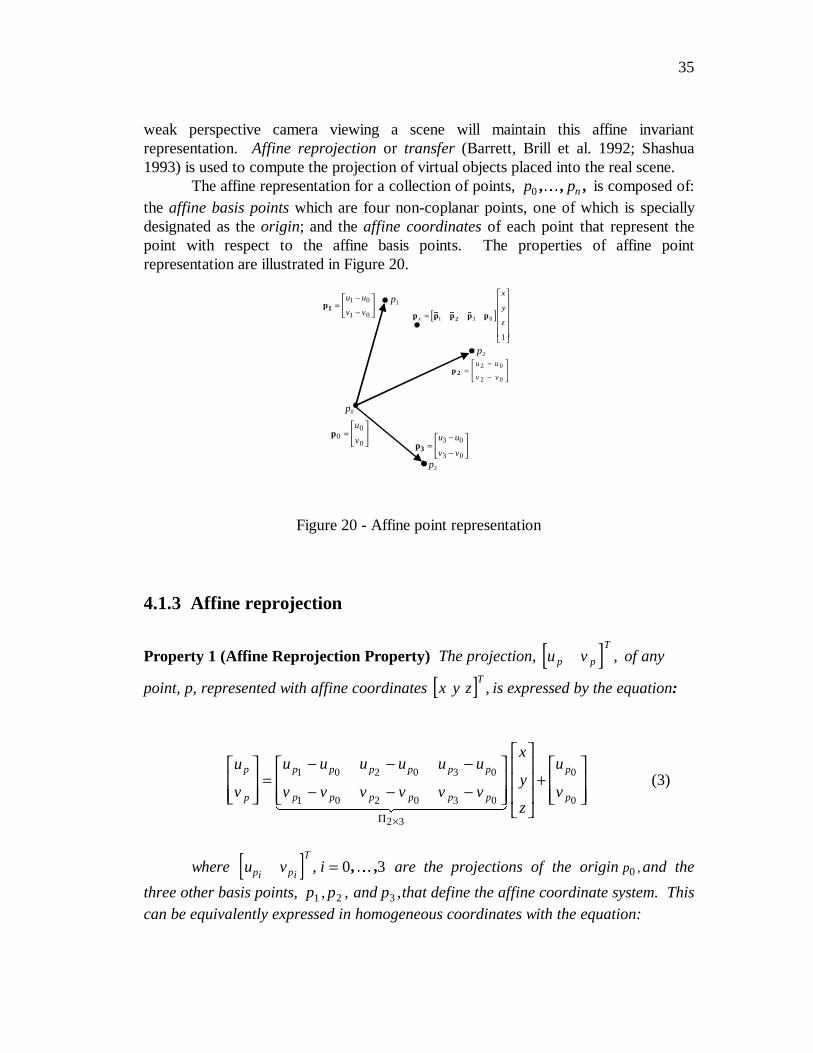
35
weak perspective camera viewing a scene will maintain this affine invariantrepresentation. Affine reprojection or transfer (Barrett, Brill et al. 1992; Shashua1993) is used to compute the projection of virtual objects placed into the real scene.
The affine representation for a collection of points, p pn0 , , ,� is composed of:the affine basis points which are four non-coplanar points, one of which is speciallydesignated as the origin; and the affine coordinates of each point that represent thepoint with respect to the affine basis points. The properties of affine pointrepresentation are illustrated in Figure 20.
4.1.3 Affine reprojection
Property 1 (Affine Reprojection Property) The projection, [ ]u vp p
T, of any
point, p, represented with affine coordinates [ ]x y zT
, is expressed by the equation:
u
v
u u u u u u
v v v v v v
x
y
z
u
v
p
p
p p p p p p
p p p p p p
p
p
=− − −
− − −
+
×
1 0 2 0 3 0
1 0 2 0 3 0
2 3
0
0
������ �������
(3)
where [ ]u v ipi pi
T, = 0 3, ,� are the projections of the origin p0 , and the
three other basis points, p p1 2 3, , and p ,that define the affine coordinate system. Thiscan be equivalently expressed in homogeneous coordinates with the equation:
p1
p2
p3
*
p 2 =−
−
u u
v v
2 0
2 0
*p3 =−
−
u u
v v
3 0
3 0
*p1 =−
−
u u
v v
1 0
1 0 [ ]p p p p p2x
x
y
z=
& & &
1 3 0
1
p0
p00
0=
u
v
Figure 20 - Affine point representation
36
u
v
u u u u u u u
v v v v v v v
x
y
z
p
p
p p p p p p p
p p p p p p p
1 0 0 0 11
1 0 2 0 3 0 0
1 0 2 0 3 0 0
3 4
=
− − −
− − −
×Π �������� ���������
. (4)
Equation 4 provides an explicit definition for the projection matrix Π3 4× seenin Equation 1 and defines the projection of a 3D point in any new image as a linearcombination of the projections of the affine basis points in that image. Calculation ofthe projection of a point on a virtual object has been reduced to knowing the locationof the projections of the affine basis points in a new image and the homogeneous affinecoordinates for the virtual point. The affine basis points will be defined by visuallytracking features in the scene and determining the projections in each new videoimage. The following property provides the technique for determining the affinecoordinates of any 3D point.
Property 2 (Affine Reconstruction Property) The affine coordinates of any pointcan be computed from Equation 4 if its projection in at least two views is known andthe projections of the affine basis points are also known in those views.
This results in an over-determined system of equations based on Equation 4.Given two views, I I1 2, , of a scene in which the projections of the affine basis points,
p p0 3, ,� , are known then the affine coordinates [ ]x y zT
1 for any point p can be
recovered from the solution of the following equation:
u
v
u
v
u u u u u u u
v v v v v v v
u u u u u u u
v v v v v v v
p
p
p
p
p p p p p p p
p p p p p p p
p p p p p p p
p p p p p p p
1
1
2
2
11
01
21
01
31
01
01
11
01
21
01
31
01
01
12
02
22
02
32
02
02
12
02
22
02
32
02
02
=
− − −
− − −
− − −
− − −
x
y
z
1
(5)
where [ ]u vpi
pi T
and [ ]u vp ji
p ji
T
are the projections of point p and affine
basis point pj, respectively, in image Ii.
37
4.1.4 Affine projection matrix
One performance goal for an augmented reality system is the ability to operatein real-time which will often limit the photorealism possible in rendering the virtualobjects. As a minimum the very basic operation of hidden surface removal (Foley, vanDam et al. 1990) must be performed to have a correct visualization of anythree-dimensional virtual object. Hidden surface removal uses a front-to-backordering of surfaces to determine visibility. The front-to-back ordering is obtained byassigning a depth to each rendered point that represents its distance from theviewpoint. The following two properties extend the familiar notions of “image plane”and “viewing direction” to the affine representation. This extension allows for therequired front-to-back ordering of virtual surfaces and use of hardware-supportedrendering via z-buffering. The image plane and viewing direction define a 3Dcoordinate system that describes the orientation of the camera. The graphics systemcan operate entirely within this global affine coordinate system and completely ignorethe original object representation.
Property 3 (Affine Image Plane) Let χ and ψ be the homogeneous vectorscorresponding to the first and second row of Π 2 3× ,respectively. (1) The vectors χand ψ are the directions of the rows and columns of the camera, respectively,expressed in the coordinate frame of the affine basis points. (2) The affine imageplane of the camera is the plane spanned by the vectors χ and ψ .
The unique direction in space along which all points project to a single pixel inthe image defines the viewing direction of a camera under our model of weakperspective projection. In the affine case, this direction is expressed mathematically asthe null-space of the matrix Π 2 3× :
Property 4 (Affine Viewing Direction) When expressed in the coordinate frame ofthe affine basis points, the viewing direction, ζ , of the camera is given by the crossproduct
ζ χ ψ= × . (6)
Property 4 guarantees that the set of points { }p t t+ ∈ℜζ , that defines the line
of sight of a point p will project to the same pixel under Equation 3. The z-buffervalue needed for hidden surface removal that is assigned to every point is the dot
product [ ]ζ T Tp0 ⋅ . The actual magnitude of this value is irrelevant: the important
characteristic is that the front-to-back order of virtual points rendered to the samepixel is correctly maintained along the camera viewing direction.
38
The affine image plane and viewing direction vectors define a 3D coordinatesystem that in general will not be an orthonormal reference frame in Euclidean 3Dspace. Despite this, correct visible surface rendering of any point
[ ]x y zT
1 defined in the global affine coordinate system can be performed by
applying the transformation:
u
v
w
u u u u u u u
v v v v v v v
x
y
z
p p p p p p p
p p p p p p p
T
1
0
1 1
1 0 2 0 3 0 0
1 0 2 0 3 0 0
4 4
=
− − −
− − −
×
ζ
0Π
������� ��������
, (7)
where u and v are the graphic image coordinates of the point and w is its assignedz-buffer value.
Π 4 4× has the same form as the viewing matrix that is commonly used incomputer graphics systems to perform transforms of graphic objects. The structuralsimilarity allows standard graphics hardware to be used for real-time rendering ofobjects defined in the affine coordinate system developed here. In our system, aSilicon Graphics Infinite Reality Engine is directly used to render virtual objects withhardware-supported hidden surface removal.
4.1.5 Virtual object placement
In order to use the affine projection matrix Π4 4× to render the virtual objects,those objects must be represented in the global affine coordinate system defined by thetracked basis points. The 3D object-centered Euclidean coordinate system thatcommonly describes a virtual object must be transformed to the common affinecoordinate system developed in the previous sections. The calculation of thisobject-to-affine transform is done at runtime. In the simplest approach, the userinteractively specifies this transform by placing a real object in the scene that defines abounding box for the virtual object. The bounding box is defined by specifying thelocation of the x, y, z axes and the origin of the bounding box. In two separate viewsof the scene the user specifies these four locations. From these four pointcorrespondences and the affine projection matrices, Π4 4× , computed in the twoimages, the affine coordinates for the points, a a a ax y z o, , , , are computed using the
affine reconstruction property (Section 4.1.3). Assuming that the virtual object’scoordinate system has been scaled to a bounding box of unit size, the object-to-worldtransform, O4 4× , from Figure 2 can be calculated from the solution of
39
[ ]a a a a Ox y z o =
×4 4
1 0 0 0
0 1 0 0
0 0 1 0
1 1 1 1
(8)
In this case, the world coordinate system is the common affine coordinate system. Thecomputed transform handles both the change to the common affine coordinate systemand placement in the 3D scene.
The user can be further supported in the process of interactively placing virtualobjects. By using results from stereo vision, the system can impose constraints onwhere the user is allowed to specify points representing physical locations in 3D space.Once the user specifies a point in one image, the epipolar constraint (Shapiro,Zisserman et al. 1995) determines the line in the second image on which the projectionof this point must lie. The user specification of the point in the second image can be“snapped” to the nearest point on this epipolar line. Additionally, techniques forconstraining points to be collinear or coplanar with physical edges and surfaces areavailable (Kutulakos and Vallino 1996a).
4.1.6 Virtual object rendering
The affine projection matrix Π 4 4× will correctly render virtual objects formerging with the video image provided that those objects are represented in the globalaffine coordinate system. The projected pixel locations are computed in thecoordinate system of the image plane of the feature tracking system. This 2Dcoordinate system needs to be registered with the 2D projection created when thegraphics subsystem renders the virtual objects. There may be an aspect ratioadjustment and translation that needs to be computed. If this transform is computedcorrectly then, given the affine coordinates of a real point, it is possible to render avirtual marker that will exactly overlay the real point in the merged augmented realityimage. This video-to-graphics transform, Tgv , is computed by knowing the locations
of three marks in both the graphics and video images. The graphics subsystem createsan alignment pattern that the tracker subsystem digitizes. Figure 21 shows thealignment pattern we use. After digitizing the image the tracker determines thelocation of the three alignment marks. The graphics subsystem provides the locationof the fiducials in its window and the transform Tgv between digitized image frame
and graphics frame is obtained by solving
[ ] [ ]g g g T i i i1 2 3 1 2 3= gv (9)
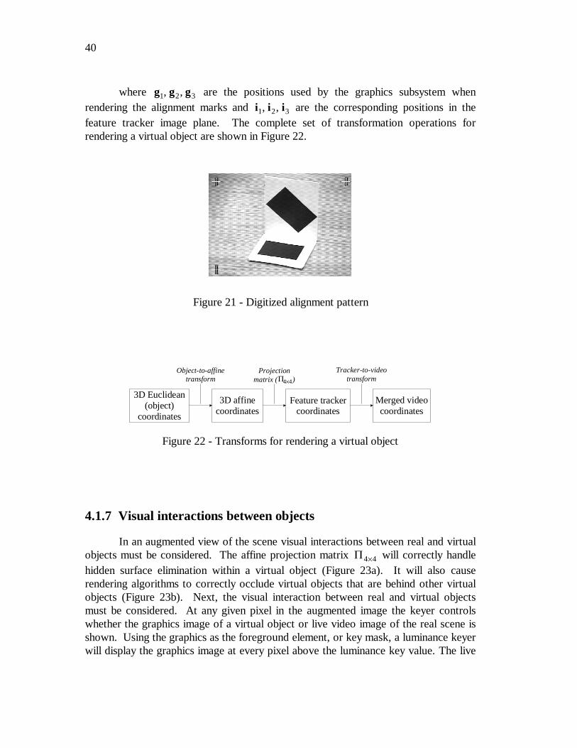
40
where g g g1 2 3, , are the positions used by the graphics subsystem whenrendering the alignment marks and i i i1 2 3, , are the corresponding positions in thefeature tracker image plane. The complete set of transformation operations forrendering a virtual object are shown in Figure 22.
4.1.7 Visual interactions between objects
In an augmented view of the scene visual interactions between real and virtualobjects must be considered. The affine projection matrix Π4 4× will correctly handlehidden surface elimination within a virtual object (Figure 23a). It will also causerendering algorithms to correctly occlude virtual objects that are behind other virtualobjects (Figure 23b). Next, the visual interaction between real and virtual objectsmust be considered. At any given pixel in the augmented image the keyer controlswhether the graphics image of a virtual object or live video image of the real scene isshown. Using the graphics as the foreground element, or key mask, a luminance keyerwill display the graphics image at every pixel above the luminance key value. The live
Figure 21 - Digitized alignment pattern
3D Euclidean(object)
coordinates
3D affinecoordinates
Feature trackercoordinates
Merged videocoordinates
Object-to-affinetransform
Projectionmatrix ( )Π4 4×
Tracker-to-videotransform
Figure 22 - Transforms for rendering a virtual object
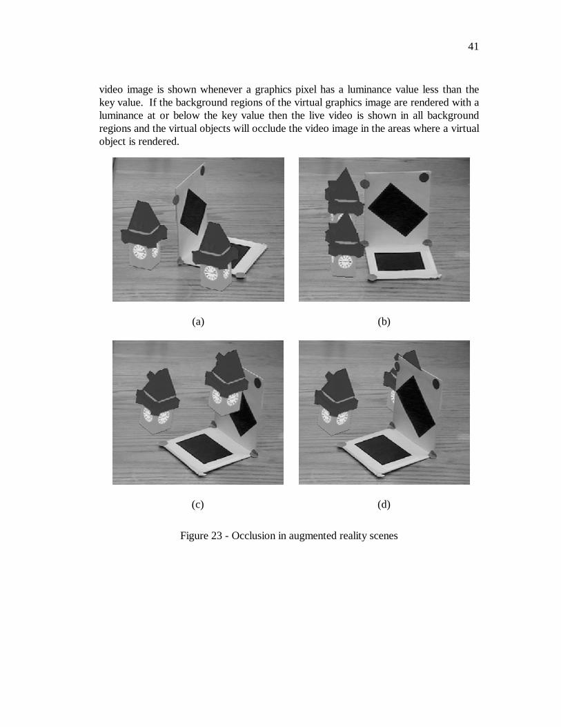
41
video image is shown whenever a graphics pixel has a luminance value less than thekey value. If the background regions of the virtual graphics image are rendered with aluminance at or below the key value then the live video is shown in all backgroundregions and the virtual objects will occlude the video image in the areas where a virtualobject is rendered.
(a) (b)
(c) (d)
Figure 23 - Occlusion in augmented reality scenes
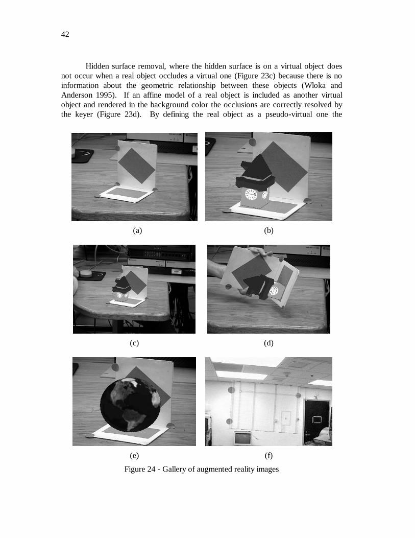
42
Hidden surface removal, where the hidden surface is on a virtual object doesnot occur when a real object occludes a virtual one (Figure 23c) because there is noinformation about the geometric relationship between these objects (Wloka andAnderson 1995). If an affine model of a real object is included as another virtualobject and rendered in the background color the occlusions are correctly resolved bythe keyer (Figure 23d). By defining the real object as a pseudo-virtual one the
(a) (b)
(c) (d)
(e) (f)
Figure 24 - Gallery of augmented reality images
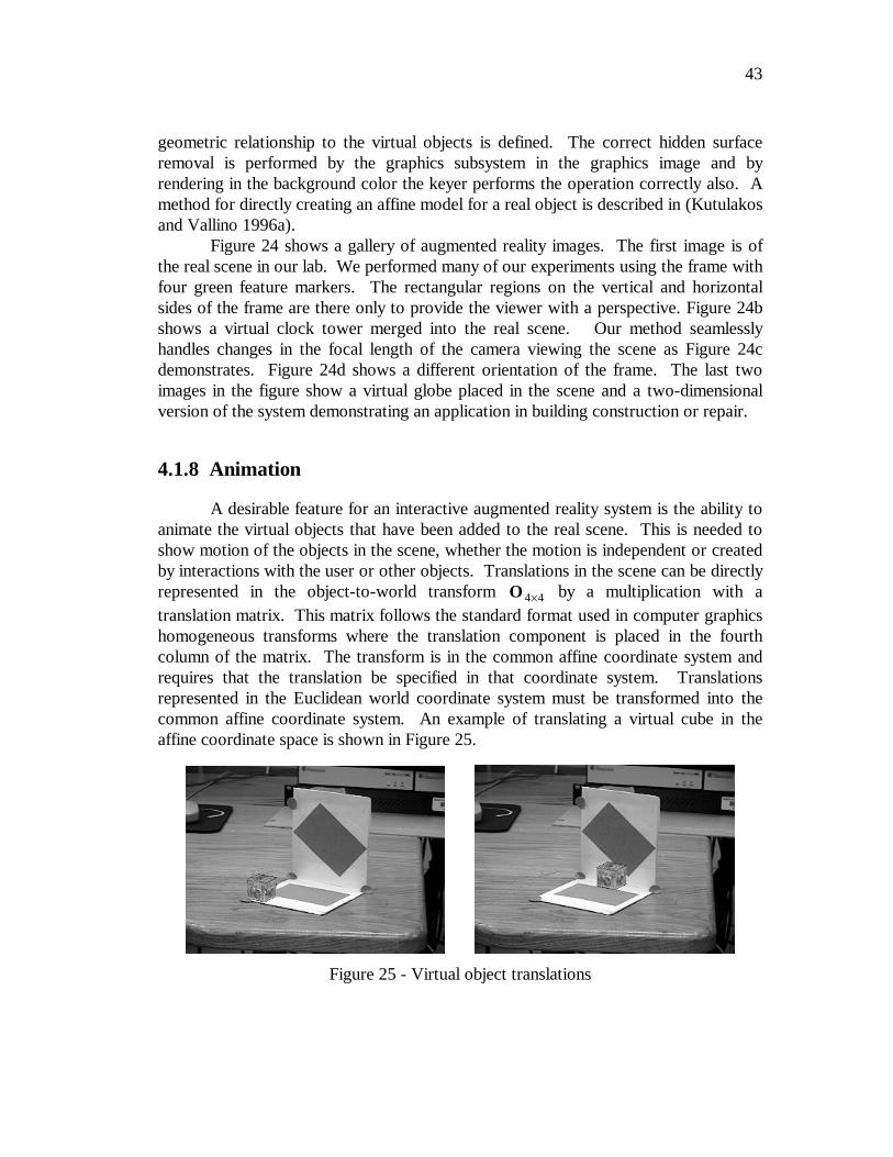
43
geometric relationship to the virtual objects is defined. The correct hidden surfaceremoval is performed by the graphics subsystem in the graphics image and byrendering in the background color the keyer performs the operation correctly also. Amethod for directly creating an affine model for a real object is described in (Kutulakosand Vallino 1996a).
Figure 24 shows a gallery of augmented reality images. The first image is ofthe real scene in our lab. We performed many of our experiments using the frame withfour green feature markers. The rectangular regions on the vertical and horizontalsides of the frame are there only to provide the viewer with a perspective. Figure 24bshows a virtual clock tower merged into the real scene. Our method seamlesslyhandles changes in the focal length of the camera viewing the scene as Figure 24cdemonstrates. Figure 24d shows a different orientation of the frame. The last twoimages in the figure show a virtual globe placed in the scene and a two-dimensionalversion of the system demonstrating an application in building construction or repair.
4.1.8 Animation
A desirable feature for an interactive augmented reality system is the ability toanimate the virtual objects that have been added to the real scene. This is needed toshow motion of the objects in the scene, whether the motion is independent or createdby interactions with the user or other objects. Translations in the scene can be directlyrepresented in the object-to-world transform O4 4× by a multiplication with atranslation matrix. This matrix follows the standard format used in computer graphicshomogeneous transforms where the translation component is placed in the fourthcolumn of the matrix. The transform is in the common affine coordinate system andrequires that the translation be specified in that coordinate system. Translationsrepresented in the Euclidean world coordinate system must be transformed into thecommon affine coordinate system. An example of translating a virtual cube in theaffine coordinate space is shown in Figure 25.
Figure 25 - Virtual object translations
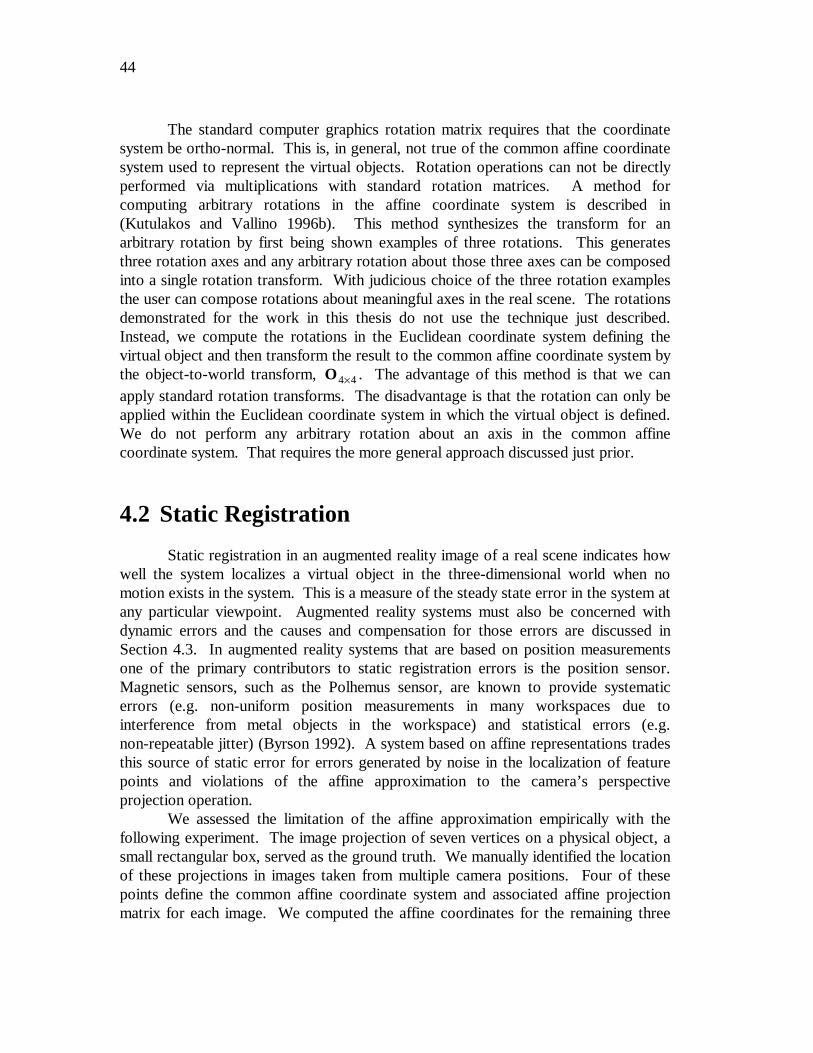
44
The standard computer graphics rotation matrix requires that the coordinatesystem be ortho-normal. This is, in general, not true of the common affine coordinatesystem used to represent the virtual objects. Rotation operations can not be directlyperformed via multiplications with standard rotation matrices. A method forcomputing arbitrary rotations in the affine coordinate system is described in(Kutulakos and Vallino 1996b). This method synthesizes the transform for anarbitrary rotation by first being shown examples of three rotations. This generatesthree rotation axes and any arbitrary rotation about those three axes can be composedinto a single rotation transform. With judicious choice of the three rotation examplesthe user can compose rotations about meaningful axes in the real scene. The rotationsdemonstrated for the work in this thesis do not use the technique just described.Instead, we compute the rotations in the Euclidean coordinate system defining thevirtual object and then transform the result to the common affine coordinate system bythe object-to-world transform, O4 4× . The advantage of this method is that we canapply standard rotation transforms. The disadvantage is that the rotation can only beapplied within the Euclidean coordinate system in which the virtual object is defined.We do not perform any arbitrary rotation about an axis in the common affinecoordinate system. That requires the more general approach discussed just prior.
4.2 Static Registration
Static registration in an augmented reality image of a real scene indicates howwell the system localizes a virtual object in the three-dimensional world when nomotion exists in the system. This is a measure of the steady state error in the system atany particular viewpoint. Augmented reality systems must also be concerned withdynamic errors and the causes and compensation for those errors are discussed inSection 4.3. In augmented reality systems that are based on position measurementsone of the primary contributors to static registration errors is the position sensor.Magnetic sensors, such as the Polhemus sensor, are known to provide systematicerrors (e.g. non-uniform position measurements in many workspaces due tointerference from metal objects in the workspace) and statistical errors (e.g.non-repeatable jitter) (Byrson 1992). A system based on affine representations tradesthis source of static error for errors generated by noise in the localization of featurepoints and violations of the affine approximation to the camera’s perspectiveprojection operation.
We assessed the limitation of the affine approximation empirically with thefollowing experiment. The image projection of seven vertices on a physical object, asmall rectangular box, served as the ground truth. We manually identified the locationof these projections in images taken from multiple camera positions. Four of thesepoints define the common affine coordinate system and associated affine projectionmatrix for each image. We computed the affine coordinates for the remaining three
45
points from their projection in two images using the Affine Reconstruction Property.The predicted projections of these points were computed in each of the other imagesby means of the Affine Reprojection Property. As the camera distance to the objectincreased, we increased the focal length of the camera zoom lens in order to keep theobject’s size constant and the registration errors comparable. The camera followed aroughly circular path around the box in a horizontal plane at distances up to 5 metersfrom the box. Figure 26 shows the camera positions used for computing the staticregistration errors. The positions are expressed in units of the common affinecoordinate system. The affine coordinates for the test point were computed from two
images near the position ( )− × ×15 10 05 104 4. , . .
Over the range of motions considered, the static registration error remainswithin 15 pixels in the 512 480× images we processed as shown in the plots of errorsin Figure 27. The data in an error plot corresponds to the positions in Figure 26 withthe same line style. These results show, as expected, that the affine approximation toperspective leads to errors as the distance to the object decreases (Boufama, Weinshallet al. 1994). A projective invariant representation has the potential to reduce the errorat the shorter distances to the object (Section 5.1.2).
4.3 Dynamic Registration and System Latency
Latency in an augmented reality system is a major concern. Several researchefforts (Azuma and Bishop 1994; Holloway 1997) have addressed the issue. Systemlatency causes the images or haptic feedback to lag behind or “swim around” in thereal scene. User motion triggers a transient response in which the motion of the
−4 −3.5 −3 −2.5 −2 −1.5 −1 −0.5 0 0.5 1
x 104
−3
−2.5
−2
−1.5
−1
−0.5
0
0.5
1
1.5
2x 10
4
Affine y−coordinate
Affi
ne x
−co
ordi
nate
Affine camera position
Figure 26 - Positions of the camera in affine spaceduring static registration testing
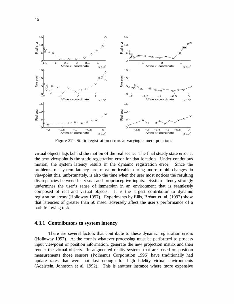
46
virtual objects lags behind the motion of the real scene. The final steady state error atthe new viewpoint is the static registration error for that location. Under continuousmotion, the system latency results in the dynamic registration error. Since theproblems of system latency are most noticeable during more rapid changes inviewpoint this, unfortunately, is also the time when the user most notices the resultingdiscrepancies between his visual and proprioceptive inputs. System latency stronglyundermines the user’s sense of immersion in an environment that is seamlesslycomposed of real and virtual objects. It is the largest contributor to dynamicregistration errors (Holloway 1997). Experiments by Ellis, Bréant et. al. (1997) showthat latencies of greater than 50 msec. adversely affect the user’s performance of apath following task.
4.3.1 Contributors to system latency
There are several factors that contribute to these dynamic registration errors(Holloway 1997). At the core is whatever processing must be performed to processinput viewpoint or position information, generate the new projection matrix and thenrender the virtual objects. In augmented reality systems that are based on positionmeasurements those sensors (Polhemus Corporation 1996) have traditionally hadupdate rates that were not fast enough for high fidelity virtual environments(Adelstein, Johnston et al. 1992). This is another instance where more expensive
−1.5 −1 −0.5 0 0.5 1
x 104
0
5
10
15Pi
xel e
rror
Affine x−coordinate−1 0 1
x 104
0
5
10
15
Pixe
l erro
r
Affine x−coordinate
−2 −1 0 1
x 104
0
5
10
15
Pixe
l erro
r
Affine x−coordinate−2 −1.5 −1 −0.5 0
x 104
0
5
10
15
Pixe
l erro
r
Affine x−coordinate
−2 −1.5 −1 −0.5 0
x 104
0
5
10
15
Pixe
l erro
r
Affine x−coordinate−2.5 −2 −1.5 −1 −0.5 0
x 104
0
5
10
15
Pixe
l erro
r
Affine x−coordinate
Figure 27 - Static registration errors at varying camera positions
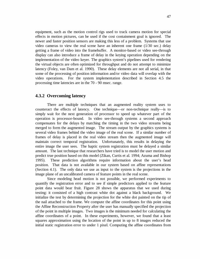
47
equipment, such as the motion control rigs used to track camera motion for specialeffects in motion pictures, can be used if the cost containment goal is ignored. Thenewer and faster position sensors are making this less of a problem. Systems that usevideo cameras to view the real scene have an inherent one frame (1/30 sec.) delaygetting a frame of video into the framebuffer. A monitor-based or video see-throughdisplay can also introduce a frame of delay in the keying operation depending on theimplementation of the video keyer. The graphics system’s pipelines used for renderingthe virtual objects are often optimized for throughput and do not attempt to minimizelatency (Foley, van Dam et al. 1990). These delay elements are not all serial, in thatsome of the processing of position information and/or video data will overlap with thevideo operations. For the system implementation described in Section 4.5 theprocessing time latencies are in the 70 - 90 msec. range.
4.3.2 Overcoming latency
There are multiple techniques that an augmented reality system uses tocounteract the effects of latency. One technique—or non-technique really—is tosimply wait for the next generation of processor to speed up whatever part of theoperation is processor-bound. In video see-through systems a second approachcompensates for the delays by matching the timing in the two video streams beingmerged to form the augmented image. The stream output by the graphics systems isseveral video frames behind the video image of the real scene. If a similar number offrames of delay is placed in the real video stream then the augmented image willmaintain correct temporal registration. Unfortunately, this results in delaying theentire image the user sees. The haptic system registration must be delayed a similaramount. The last technique that researchers have tried is to model the user motion andpredict true position based on this model (Zikan, Curtis et al. 1994; Azuma and Bishop1995). These prediction algorithms require information about the user’s headposition. That data is not available in our system based on affine representations(Section 4.1). The only data we use as input to the system is the projections in theimage plane of an uncalibrated camera of feature points in the real scene.
Since modeling head motion is not possible, we performed experiments toquantify the registration error and to see if simple predictors applied to the featurepoint data would bear fruit. Figure 28 shows the apparatus that we used duringtesting: it consisted of a high contrast white dot against a black background. Weinitialize the test by determining the projection for the white dot painted on the tip ofthe nail attached to the frame. We compute the affine coordinates for this point usingthe Affine Reconstruction Property after the user has manually specified the projectionof the point in multiple images. Two images is the minimum needed for calculating theaffine coordinates of a point. In these experiments, however, we found that a leastsquares approximation using the location of the point in up to 8 images reduced theinitial static registration error to under 1 pixel. Computing the affine coordinates from
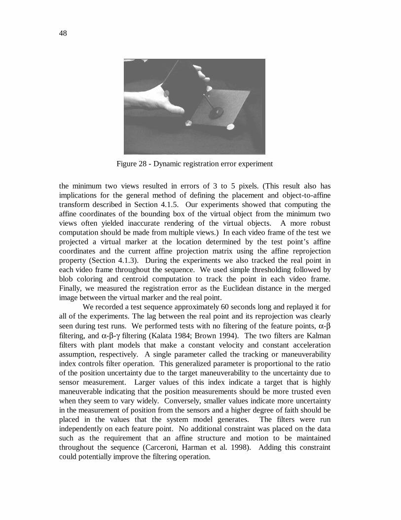
48
the minimum two views resulted in errors of 3 to 5 pixels. (This result also hasimplications for the general method of defining the placement and object-to-affinetransform described in Section 4.1.5. Our experiments showed that computing theaffine coordinates of the bounding box of the virtual object from the minimum twoviews often yielded inaccurate rendering of the virtual objects. A more robustcomputation should be made from multiple views.) In each video frame of the test weprojected a virtual marker at the location determined by the test point’s affinecoordinates and the current affine projection matrix using the affine reprojectionproperty (Section 4.1.3). During the experiments we also tracked the real point ineach video frame throughout the sequence. We used simple thresholding followed byblob coloring and centroid computation to track the point in each video frame.Finally, we measured the registration error as the Euclidean distance in the mergedimage between the virtual marker and the real point.
We recorded a test sequence approximately 60 seconds long and replayed it forall of the experiments. The lag between the real point and its reprojection was clearlyseen during test runs. We performed tests with no filtering of the feature points, α-βfiltering, and α-β-γ filtering (Kalata 1984; Brown 1994). The two filters are Kalmanfilters with plant models that make a constant velocity and constant accelerationassumption, respectively. A single parameter called the tracking or maneuverabilityindex controls filter operation. This generalized parameter is proportional to the ratioof the position uncertainty due to the target maneuverability to the uncertainty due tosensor measurement. Larger values of this index indicate a target that is highlymaneuverable indicating that the position measurements should be more trusted evenwhen they seem to vary widely. Conversely, smaller values indicate more uncertaintyin the measurement of position from the sensors and a higher degree of faith should beplaced in the values that the system model generates. The filters were runindependently on each feature point. No additional constraint was placed on the datasuch as the requirement that an affine structure and motion to be maintainedthroughout the sequence (Carceroni, Harman et al. 1998). Adding this constraintcould potentially improve the filtering operation.
Figure 28 - Dynamic registration error experiment
49
During the initial tests, we placed a second marker in the graphic image toassess how well our simple algorithm was tracking the real point in the video frame.This mark indicated the detected location of the test point. We observed that thismarker lagged the real test point in the image though not as far as the reprojectedvirtual point lagged. During the offline data analysis the location of the test point infuture frames is available and we used this information when computing the errordistance. At each frame in an experimental run, we calculated the error as theEuclidean distance between the location of the reprojected virtual marker and thedetected position of the real point at the next time interval. Considering the videohardware that adds at least a one frame delay before a frame of video is available tothe tracker to find the real point this is a reasonable adjustment. The lag in our systemhas been measured to be approximately three frames (Section 4.5.1). We observed thetracked point to qualitatively lag in the augmented image about half the amount of thevirtual point. This qualitative observation combined with our measured latencyprovides further justification for the choice of a one frame adjustment as part of thedata analysis.
Figure 29 shows the plots of mean pixel error for two filter combinations.
The mean of the Euclidean distances between the position of the target point inthe video frame and the reprojection of its affine coordinates for several filterconfigurations are given in Figure 30. One significant trend the reader should note inthe data is that the mean error consistently decreases for forward prediction values of2 to 3 frames of video. This data confirms the values for latency that we measured inthe system. It also matches our experience when running the system which from avisual inspection indicated that 3 frames of prediction gave the best result qualitatively.The specific method of filtering does not have a significant quantitative effect on theregistration error compared to the effect of the prediction value selected. This may bedue to the plant assumptions of constant velocity (α−β) and constant acceleration(α−β−γ) in that neither of them accurately models the non-linear motion of the realtest point through the test sequence. The slightly better results of the α−β−γ filter at
No filter, 0 frame prediction
0
5
10
15
20
25
30
35
1 201 401 601 801 1001 1201 1401 1601
Time (video frame)
Mea
n e
rro
r (p
ixel
s)
α−β filter (0.75), 3 frame prediction
0
5
10
15
20
25
30
35
1 201 401 601 801 1001 1201 1401 1601
Time (video frame)
Mea
n e
rro
r (p
ixel
s)
Figure 29 - Sample registration error data
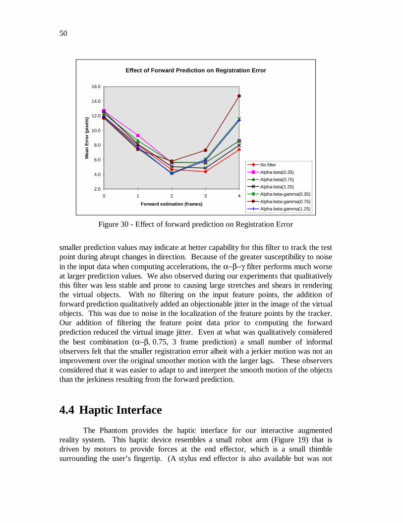
50
smaller prediction values may indicate at better capability for this filter to track the testpoint during abrupt changes in direction. Because of the greater susceptibility to noisein the input data when computing accelerations, the α−β−γ filter performs much worseat larger prediction values. We also observed during our experiments that qualitativelythis filter was less stable and prone to causing large stretches and shears in renderingthe virtual objects. With no filtering on the input feature points, the addition offorward prediction qualitatively added an objectionable jitter in the image of the virtualobjects. This was due to noise in the localization of the feature points by the tracker.Our addition of filtering the feature point data prior to computing the forwardprediction reduced the virtual image jitter. Even at what was qualitatively consideredthe best combination (α−β, 0.75, 3 frame prediction) a small number of informalobservers felt that the smaller registration error albeit with a jerkier motion was not animprovement over the original smoother motion with the larger lags. These observersconsidered that it was easier to adapt to and interpret the smooth motion of the objectsthan the jerkiness resulting from the forward prediction.
4.4 Haptic Interface
The Phantom provides the haptic interface for our interactive augmentedreality system. This haptic device resembles a small robot arm (Figure 19) that isdriven by motors to provide forces at the end effector, which is a small thimblesurrounding the user’s fingertip. (A stylus end effector is also available but was not
Effect of Forward Prediction on Registration Error
2.0
4.0
6.0
8.0
10.0
12.0
14.0
16.0
0 1 2 3 4
Forward estimation (frames)
Mea
n E
rro
r (p
ixel
s)
No filter
Alpha-beta(0.35)
Alpha-beta(0.75)
Alpha-beta(1.25)
Alpha-beta-gamma(0.35)
Alpha-beta-gamma(0.75)
Alpha-beta-gamma(1.25)
Figure 30 - Effect of forward prediction on Registration Error
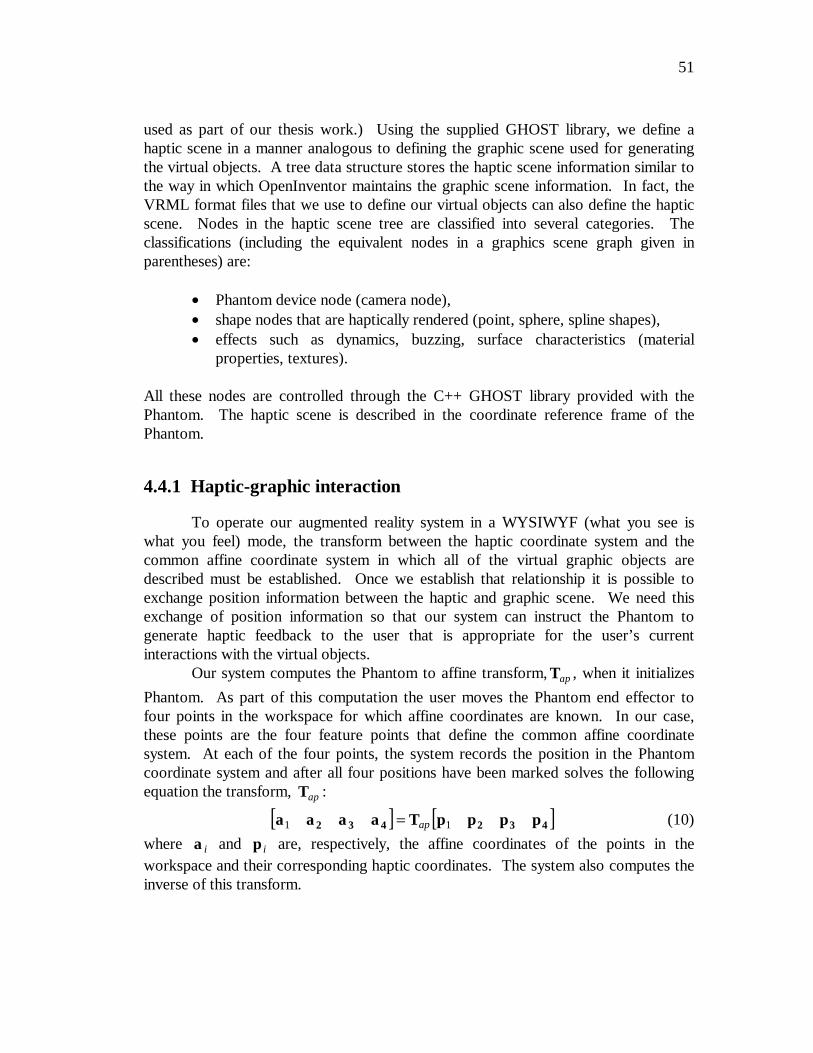
51
used as part of our thesis work.) Using the supplied GHOST library, we define ahaptic scene in a manner analogous to defining the graphic scene used for generatingthe virtual objects. A tree data structure stores the haptic scene information similar tothe way in which OpenInventor maintains the graphic scene information. In fact, theVRML format files that we use to define our virtual objects can also define the hapticscene. Nodes in the haptic scene tree are classified into several categories. Theclassifications (including the equivalent nodes in a graphics scene graph given inparentheses) are:
• Phantom device node (camera node),• shape nodes that are haptically rendered (point, sphere, spline shapes),• effects such as dynamics, buzzing, surface characteristics (material
properties, textures). All these nodes are controlled through the C++ GHOST library provided with thePhantom. The haptic scene is described in the coordinate reference frame of thePhantom.
4.4.1 Haptic-graphic interaction
To operate our augmented reality system in a WYSIWYF (what you see iswhat you feel) mode, the transform between the haptic coordinate system and thecommon affine coordinate system in which all of the virtual graphic objects aredescribed must be established. Once we establish that relationship it is possible toexchange position information between the haptic and graphic scene. We need thisexchange of position information so that our system can instruct the Phantom togenerate haptic feedback to the user that is appropriate for the user’s currentinteractions with the virtual objects.
Our system computes the Phantom to affine transform, Tap , when it initializes
Phantom. As part of this computation the user moves the Phantom end effector tofour points in the workspace for which affine coordinates are known. In our case,these points are the four feature points that define the common affine coordinatesystem. At each of the four points, the system records the position in the Phantomcoordinate system and after all four positions have been marked solves the followingequation the transform, Tap :
[ ] [ ]a a a a T p p p p2 3 4 2 3 41 1= ap (10)
where a i and p i are, respectively, the affine coordinates of the points in theworkspace and their corresponding haptic coordinates. The system also computes theinverse of this transform.
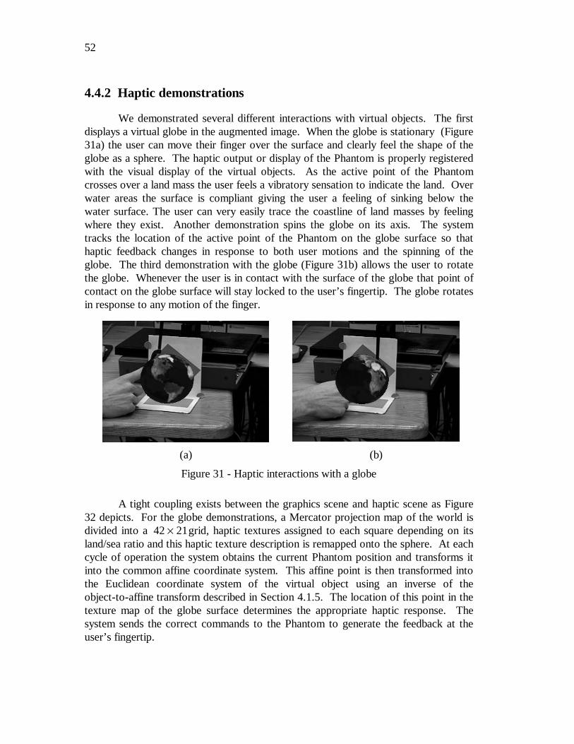
52
4.4.2 Haptic demonstrations
We demonstrated several different interactions with virtual objects. The firstdisplays a virtual globe in the augmented image. When the globe is stationary (Figure31a) the user can move their finger over the surface and clearly feel the shape of theglobe as a sphere. The haptic output or display of the Phantom is properly registeredwith the visual display of the virtual objects. As the active point of the Phantomcrosses over a land mass the user feels a vibratory sensation to indicate the land. Overwater areas the surface is compliant giving the user a feeling of sinking below thewater surface. The user can very easily trace the coastline of land masses by feelingwhere they exist. Another demonstration spins the globe on its axis. The systemtracks the location of the active point of the Phantom on the globe surface so thathaptic feedback changes in response to both user motions and the spinning of theglobe. The third demonstration with the globe (Figure 31b) allows the user to rotatethe globe. Whenever the user is in contact with the surface of the globe that point ofcontact on the globe surface will stay locked to the user’s fingertip. The globe rotatesin response to any motion of the finger.
A tight coupling exists between the graphics scene and haptic scene as Figure32 depicts. For the globe demonstrations, a Mercator projection map of the world isdivided into a 42 21× grid, haptic textures assigned to each square depending on itsland/sea ratio and this haptic texture description is remapped onto the sphere. At eachcycle of operation the system obtains the current Phantom position and transforms itinto the common affine coordinate system. This affine point is then transformed intothe Euclidean coordinate system of the virtual object using an inverse of theobject-to-affine transform described in Section 4.1.5. The location of this point in thetexture map of the globe surface determines the appropriate haptic response. Thesystem sends the correct commands to the Phantom to generate the feedback at theuser’s fingertip.
(a) (b)
Figure 31 - Haptic interactions with a globe
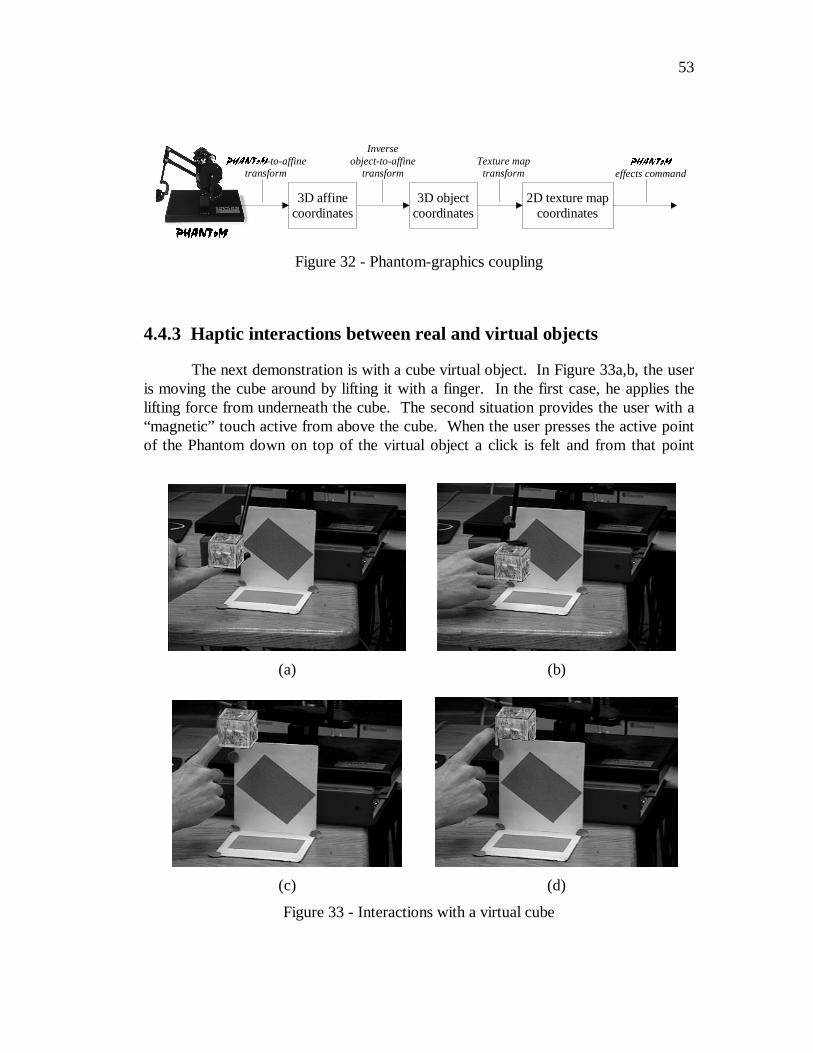
53
4.4.3 Haptic interactions between real and virtual objects
The next demonstration is with a cube virtual object. In Figure 33a,b, the useris moving the cube around by lifting it with a finger. In the first case, he applies thelifting force from underneath the cube. The second situation provides the user with a“magnetic” touch active from above the cube. When the user presses the active pointof the Phantom down on top of the virtual object a click is felt and from that point
3+$17R03+$17R0
3+$17R0-to-affinetransform
Inverseobject-to-affine
transformTexture map
transform3+$17R0
effects command
3D affinecoordinates
3D objectcoordinates
2D texture mapcoordinates
Figure 32 - Phantom-graphics coupling
(a) (b)
(c) (d)
Figure 33 - Interactions with a virtual cube
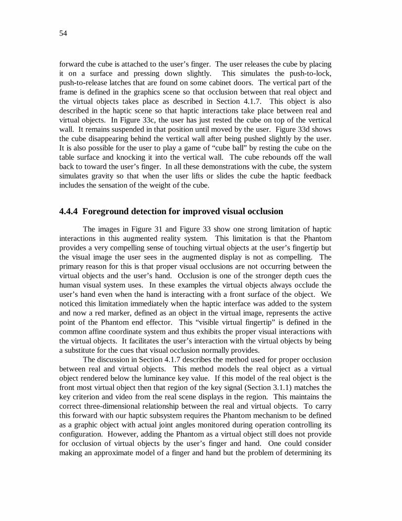
54
forward the cube is attached to the user’s finger. The user releases the cube by placingit on a surface and pressing down slightly. This simulates the push-to-lock,push-to-release latches that are found on some cabinet doors. The vertical part of theframe is defined in the graphics scene so that occlusion between that real object andthe virtual objects takes place as described in Section 4.1.7. This object is alsodescribed in the haptic scene so that haptic interactions take place between real andvirtual objects. In Figure 33c, the user has just rested the cube on top of the verticalwall. It remains suspended in that position until moved by the user. Figure 33d showsthe cube disappearing behind the vertical wall after being pushed slightly by the user.It is also possible for the user to play a game of “cube ball” by resting the cube on thetable surface and knocking it into the vertical wall. The cube rebounds off the wallback to toward the user’s finger. In all these demonstrations with the cube, the systemsimulates gravity so that when the user lifts or slides the cube the haptic feedbackincludes the sensation of the weight of the cube.
4.4.4 Foreground detection for improved visual occlusion
The images in Figure 31 and Figure 33 show one strong limitation of hapticinteractions in this augmented reality system. This limitation is that the Phantomprovides a very compelling sense of touching virtual objects at the user’s fingertip butthe visual image the user sees in the augmented display is not as compelling. Theprimary reason for this is that proper visual occlusions are not occurring between thevirtual objects and the user’s hand. Occlusion is one of the stronger depth cues thehuman visual system uses. In these examples the virtual objects always occlude theuser’s hand even when the hand is interacting with a front surface of the object. Wenoticed this limitation immediately when the haptic interface was added to the systemand now a red marker, defined as an object in the virtual image, represents the activepoint of the Phantom end effector. This “visible virtual fingertip” is defined in thecommon affine coordinate system and thus exhibits the proper visual interactions withthe virtual objects. It facilitates the user’s interaction with the virtual objects by beinga substitute for the cues that visual occlusion normally provides.
The discussion in Section 4.1.7 describes the method used for proper occlusionbetween real and virtual objects. This method models the real object as a virtualobject rendered below the luminance key value. If this model of the real object is thefront most virtual object then that region of the key signal (Section 3.1.1) matches thekey criterion and video from the real scene displays in the region. This maintains thecorrect three-dimensional relationship between the real and virtual objects. To carrythis forward with our haptic subsystem requires the Phantom mechanism to be definedas a graphic object with actual joint angles monitored during operation controlling itsconfiguration. However, adding the Phantom as a virtual object still does not providefor occlusion of virtual objects by the user’s finger and hand. One could considermaking an approximate model of a finger and hand but the problem of determining its
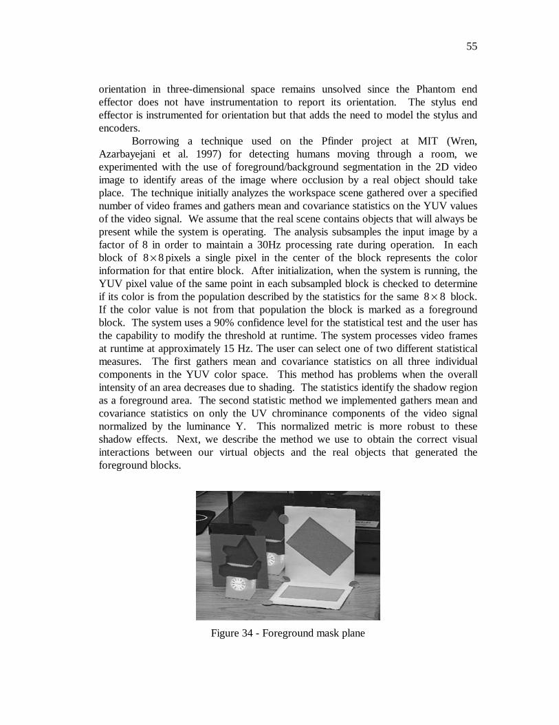
55
orientation in three-dimensional space remains unsolved since the Phantom endeffector does not have instrumentation to report its orientation. The stylus endeffector is instrumented for orientation but that adds the need to model the stylus andencoders.
Borrowing a technique used on the Pfinder project at MIT (Wren,Azarbayejani et al. 1997) for detecting humans moving through a room, weexperimented with the use of foreground/background segmentation in the 2D videoimage to identify areas of the image where occlusion by a real object should takeplace. The technique initially analyzes the workspace scene gathered over a specifiednumber of video frames and gathers mean and covariance statistics on the YUV valuesof the video signal. We assume that the real scene contains objects that will always bepresent while the system is operating. The analysis subsamples the input image by afactor of 8 in order to maintain a 30Hz processing rate during operation. In eachblock of 8 8× pixels a single pixel in the center of the block represents the colorinformation for that entire block. After initialization, when the system is running, theYUV pixel value of the same point in each subsampled block is checked to determineif its color is from the population described by the statistics for the same 8 8× block.If the color value is not from that population the block is marked as a foregroundblock. The system uses a 90% confidence level for the statistical test and the user hasthe capability to modify the threshold at runtime. The system processes video framesat runtime at approximately 15 Hz. The user can select one of two different statisticalmeasures. The first gathers mean and covariance statistics on all three individualcomponents in the YUV color space. This method has problems when the overallintensity of an area decreases due to shading. The statistics identify the shadow regionas a foreground area. The second statistic method we implemented gathers mean andcovariance statistics on only the UV chrominance components of the video signalnormalized by the luminance Y. This normalized metric is more robust to theseshadow effects. Next, we describe the method we use to obtain the correct visualinteractions between our virtual objects and the real objects that generated theforeground blocks.
Figure 34 - Foreground mask plane
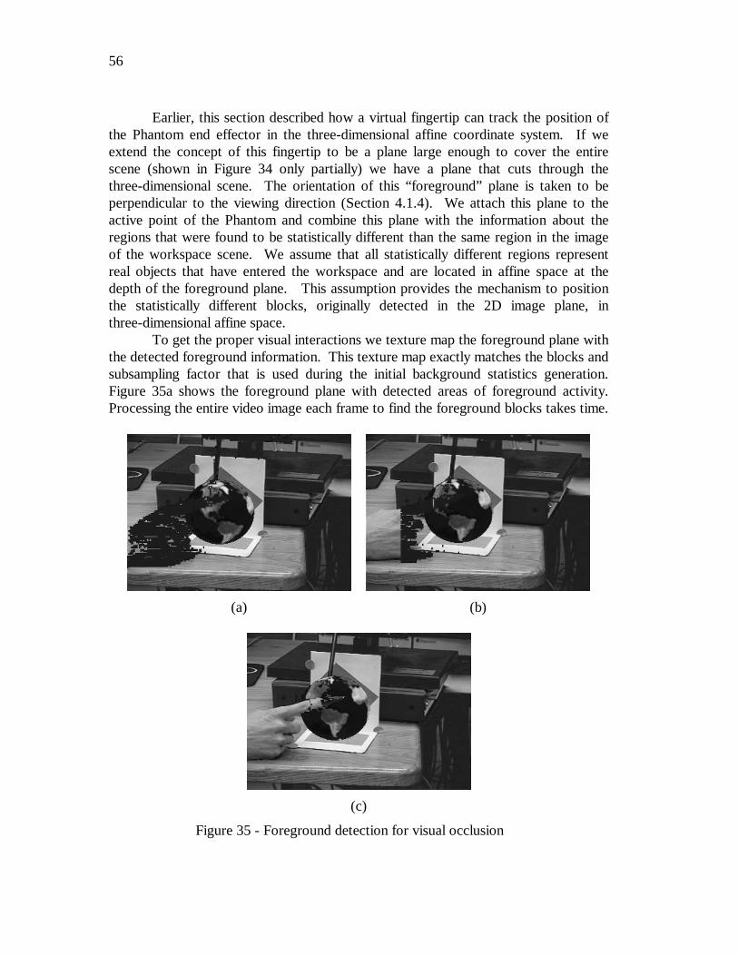
56
Earlier, this section described how a virtual fingertip can track the position ofthe Phantom end effector in the three-dimensional affine coordinate system. If weextend the concept of this fingertip to be a plane large enough to cover the entirescene (shown in Figure 34 only partially) we have a plane that cuts through thethree-dimensional scene. The orientation of this “foreground” plane is taken to beperpendicular to the viewing direction (Section 4.1.4). We attach this plane to theactive point of the Phantom and combine this plane with the information about theregions that were found to be statistically different than the same region in the imageof the workspace scene. We assume that all statistically different regions representreal objects that have entered the workspace and are located in affine space at thedepth of the foreground plane. This assumption provides the mechanism to positionthe statistically different blocks, originally detected in the 2D image plane, inthree-dimensional affine space.
To get the proper visual interactions we texture map the foreground plane withthe detected foreground information. This texture map exactly matches the blocks andsubsampling factor that is used during the initial background statistics generation.Figure 35a shows the foreground plane with detected areas of foreground activity.Processing the entire video image each frame to find the foreground blocks takes time.
(a) (b)
(c)
Figure 35 - Foreground detection for visual occlusion
57
In order to maintain a 30 Hz processing rate, a subsampling factor of 8 must beselected. The overall goal here is to find areas where the live video image shouldocclude a virtual graphic object. We only need to make this determination in pixelareas where there are projections of virtual graphic objects. Restricting theforeground checks to these areas speeds up processing and allows a smallersubsampling factor of 4. We use the projection of the bounding box of all virtualgraphic objects to define the region in which we perform foreground detection. Theforeground mask in the area where graphics are present is shown in Figure 35b.
We want the virtual graphics image to key the live video into the finalaugmented image in all the 8 8× foreground block regions that are closest to thecamera in affine space. Remember that we make the assumption that all detectedforeground activity, i.e. a real object that has entered the workspace, is located at theaffine depth of the Phantom virtual fingertip. For the virtual image to key the livevideo in a particular region the luminance of the virtual image in that region must bebelow the luminance key value. In the texture map applied to the foreground plane werender a detected foreground block as an opaque block below the luminance keyvalue. If the active point of the Phantom—and by connection the foreground planewith its texture mapped foreground blocks—is in front of all virtual objects the opaqueforeground blocks will generate a region below the luminance key value in the finalvirtual image. In contrast, when virtual objects occlude regions of the foregroundplane those objects will appear in the final virtual image and not key the live video inthe augmented image. In areas where we are not doing foreground detection or havedetected no foreground activity we need the foreground plane to have no effect on thefinal virtual image or be transparent. We use the common computer graphic techniqueof alpha channel blending (Foley, van Dam et al. 1990) to accomplish this. Alpha,commonly a fourth component—along with red, green and blue—in the specificationof a computer graphic color, is the inverse of transparency. An alpha value of 1.0 iscompletely opaque, i.e. it blocks any objects further in depth, and 0.0 is completelytransparent, i.e. it is as if the object was not present in the scene. We set alpha to 1.0in the foreground blocks and 0.0 in all other regions to get our desired result. Theforeground plane is texture mapped as transparent in regions with no foregroundactivity and opaque below the luminance key value in the detected foreground regions.The final augmented image (Figure 35c) shows the user’s finger properly occludingthe virtual object that it hides.
Our approach uses a plane in the virtual object space to represent wheremotion in the scene is taking place. This assumption of all motion occurring in a planein space is a gross simplification of reality. To avoid making this assumption requiresinformation about the depth along the viewing ray for the object projected to eachpixel in the image. There are two augmented reality systems (Wloka and Anderson1995; Kanade 1996) that use depth maps for resolving visual occlusions. Instead ofhaving a plane as a virtual object representing the real objects that entered theworkspace, these two systems create what can be visualized as a flexible sheet in thevirtual object space that conforms to the shape and location for all the visible real
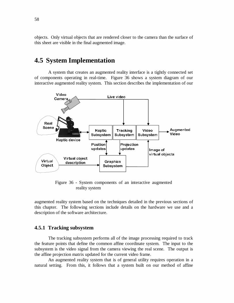
58
objects. Only virtual objects that are rendered closer to the camera than the surface ofthis sheet are visible in the final augmented image.
4.5 System Implementation
A system that creates an augmented reality interface is a tightly connected setof components operating in real-time. Figure 36 shows a system diagram of ourinteractive augmented reality system. This section describes the implementation of our
augmented reality system based on the techniques detailed in the previous sections ofthis chapter. The following sections include details on the hardware we use and adescription of the software architecture.
4.5.1 Tracking subsystem
The tracking subsystem performs all of the image processing required to trackthe feature points that define the common affine coordinate system. The input to thesubsystem is the video signal from the camera viewing the real scene. The output isthe affine projection matrix updated for the current video frame.
An augmented reality system that is of general utility requires operation in anatural setting. From this, it follows that a system built on our method of affine
9LUWXDO2EMHFW
*UDSKLFV6XEV\VWHP
9LGHR&DPHUD
+DSWLF
6XEV\VWHP
+DSWLF GHYLFH
5HDO
6FHQH7UDFNLQJ6XEV\VWHP
9LUWXDO REMHFWGHVFULSWLRQ
/LYH YLGHR
,PDJH RI
YLUWXDO REMHFWV
3URMHFWLRQXSGDWHV
3RVLWLRQXSGDWHV
$XJPHQWHG9LGHR
9LGHR
6XEV\VWHP
Figure 36 - System components of an interactive augmentedreality system
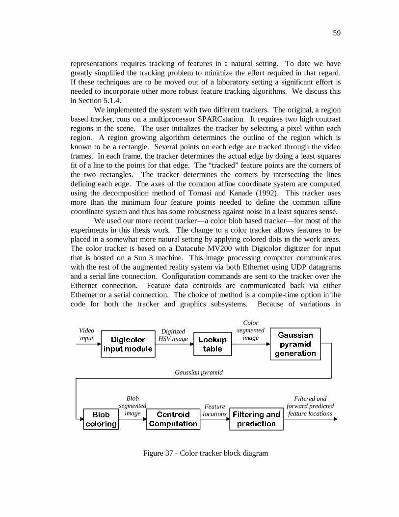
59
representations requires tracking of features in a natural setting. To date we havegreatly simplified the tracking problem to minimize the effort required in that regard.If these techniques are to be moved out of a laboratory setting a significant effort isneeded to incorporate other more robust feature tracking algorithms. We discuss thisin Section 5.1.4.
We implemented the system with two different trackers. The original, a regionbased tracker, runs on a multiprocessor SPARCstation. It requires two high contrastregions in the scene. The user initializes the tracker by selecting a pixel within eachregion. A region growing algorithm determines the outline of the region which isknown to be a rectangle. Several points on each edge are tracked through the videoframes. In each frame, the tracker determines the actual edge by doing a least squaresfit of a line to the points for that edge. The “tracked” feature points are the corners ofthe two rectangles. The tracker determines the corners by intersecting the linesdefining each edge. The axes of the common affine coordinate system are computedusing the decomposition method of Tomasi and Kanade (1992). This tracker usesmore than the minimum four feature points needed to define the common affinecoordinate system and thus has some robustness against noise in a least squares sense.
We used our more recent tracker—a color blob based tracker—for most of theexperiments in this thesis work. The change to a color tracker allows features to beplaced in a somewhat more natural setting by applying colored dots in the work areas.The color tracker is based on a Datacube MV200 with Digicolor digitizer for inputthat is hosted on a Sun 3 machine. This image processing computer communicateswith the rest of the augmented reality system via both Ethernet using UDP datagramsand a serial line connection. Configuration commands are sent to the tracker over theEthernet connection. Feature data centroids are communicated back via eitherEthernet or a serial connection. The choice of method is a compile-time option in thecode for both the tracker and graphics subsystems. Because of variations in
/RRNXS
WDEOH
*DXVVLDQ
S\UDPLG
JHQHUDWLRQ
%ORE
FRORULQJ
&HQWURLG
&RPSXWDWLRQ
)LOWHULQJ DQG
SUHGLFWLRQ
'LJLFRORU
LQSXW PRGXOH
Videoinput
DigitizedHSV image
Colorsegmented
image
Gaussian pyramid
Blobsegmented
imageFeature
locations
Filtered andforward predictedfeature locations
Figure 37 - Color tracker block diagram
60
congestion on the house Ethernet that the system is on, we found a small improvementin system latency when we switched communication to the serial line connection.Figure 37 is a block diagram for the blob tracking algorithm.
The Digicolor input module digitizes the video signal and codes it into thehue-saturation-value color space. The ability of the Digicolor to create a digitizedimage in this color space is crucial to frame rate color segmentation. The 8 bit hue andsaturation components are the input to a 16 bit lookup table that performs the colorsegmentation. The tracker decomposes the binary (0 or 255 value) color segmentedimage into a Gaussian pyramid using a 5 5× convolution kernel. The images are notre-binarized after each convolution. The tracker performs the blob coloring and laterstages of the algorithm on the host processor and not in the Datacube system. Thehost processor must transfer the pixel data from one level of the gaussian pyramid intoits memory for further processing. Transfers between system memory and DatacubeMV200 memory are relatively slow, averaging less than 200 kbytes/sec. The thirdlevel of the pyramid was the highest resolution image that the tracker can completelyprocess while maintaining a 30Hz rate. The tracker uses the blob coloring algorithmfrom Ballard and Brown (1982). After the tracker performs blob coloring at the thirdlevel of the Gaussian pyramid it could compute a more accurate localization of thefeature centroid by calculating that centroid in the full resolution color segmentedimage. Processing at full resolution requires the processor to have extended access tothe Datacube memory. The 200 kbyte/sec bandwidth to Datacube memory is not highenough to support centroid calculations on the full resolution image at 30 Hz. Due tothis limitation the tracker performs the centroid calculation on the decomposed imageand this, in turn, limits the resolution of feature localization. The minimum featurethat the tracker can detect is in the 8 8× pixel size range.
Multiple sources contribute to noise in the localization of the feature pointcentroids. One is from the color segmentation lookup table, which generates a sharpcut-off for color detection. The inputs to the color segmentation look-up table are the8 bit hue and saturation values. The output is a binary (0 or 255) color thresholdedimage. The tracker creates the look-up table using an instantaneous transition fromunacceptable to acceptable values for hue and saturation. If the edges of this transitionwere sloped instead, it should reduce the noise, and resulting jitter, associated withcolor thresholding because a small variation in hue or saturation near the acceptanceboundary would not result in large changes in the threshold output. The output of thelook-up table is the input of the Gaussian pyramid decomposition which can handle animage that is not strictly binary. We did not perform any experiments to test thispotential improvement. A second source of centroid localization error is the spatialquantization caused by the tracker performing centroid calculations on level three ofthe pyramid. The spatial quantization is directly tied to processor cycles and access tothe Datacube memory. A faster host processor and an update to the newer DatacubeMV250 system that has significantly increased the bandwidth between processor andDatacube memory would allow centroid localization to be done on the full resolutionimage. A last source of localization error that we noticed during experimentation is
61
systematic error from the video camera or the Digicolor digitizer. With at least onevideo camera we used there is a variation in color segmentation that is frame ratebased. Viewing the color segmented blobs from the Datacube system we noticed aframe-to-frame alternation between two distinct segmentation patterns. We did notinvestigate the exact source for this variation but postulate that it is a systematicvariation in the camera or the digitizer.
In our implementation the tracker transmits the feature centroid locations fromthe Datacube host system to a tracker subsystem component that runs on the graphicsworkstation. This workstation runs the graphics, haptic and video subsystems (Figure36). The graphics workstation part performs the interframe correspondence of featurepoints and the filtering and prediction operations discussed in Section 4.3.2. It wouldlogically make sense for these operations to be performed on the Sun 3 computerhosting the Datacube system. With that arrangement the image processing computercould be considered, in an abstract sense, as an affine camera position tracker and theentire tracker subsystem would run on it. We made the decision to separate theselogically connected functions based solely on the capabilities of the available hardwareand the desire to maintain a 30Hz tracking rate. The image processing computer doesnot have sufficient power to handle all the operations of the tracker subsystem.Section 4.5.5 describes the software architecture for the parts of the tracker subsystemthat run on the graphics workstation.
We measured the system latencies, discussed in Section 4.3.2, by having thegraphics subsystem send a time stamp packet to the tracker subsystem. The graphicssubsystem generates this time stamp using its high speed hardware clock. The trackersubsystem returns the time stamp in the next packet of feature data transmitted to thegraphics subsystem which then computes the elapsed time. The elapsed timecomputed does include the time to send the time stamp packet to the trackersubsystem. Strictly speaking, the system latency should only be the time from when avideo frame arrives until the video subsystem generates the augmented image based onthe video frame. Our computation thus provides an upper bound on the systemlatency. We measured latencies in the 70 to 90 msec. range.
4.5.2 Graphics subsystem
The current graphics subsystem runs on a Silicon Graphics Indigo2workstation with High Impact graphics and Impact video. The video hardwarecomponent is described in Section 4.5.4. The haptics subsystem (Section 4.5.3) runson the graphics processor also. The graphics capabilities of the system are not beingtaxed very hard because of the simple nature of the virtual objects being rendered.The high cycle demands of the haptic subsystem required a reduction in the complexityof the images. The graphics workstation ran out of processor cycles when the hapticssubsystem was running and the scene contained more than two simple cube or sphereobjects. One example of the reduction in complexity was rendering the globe with
62
larger tessellation (20 sided sphere) than desired. The functionality of the graphicssubsystem which also includes the user interface composes the main softwarecomponent of the system and is described in Section 4.5.5.
4.5.3 Haptic subsystem
The visible part of the haptic subsystem is the Phantom haptic device shown inFigure 19. This device generates force feedback to the finger of the user. It creates acompelling sense of interaction with virtual objects. Not only can the user feel thesurface texture of objects but weight of the objects is also simulated. The hardwareamplifiers and software drivers for this run on the SGI computer with the graphicssubsystem. Sensable Technologies, the manufacturer of the 3+$17R0™, provides aninterface library named GHOST and we coded to that application program interface.GHOST is a C++ class library that allows the programmer to define a haptic scenegraph in a manner analogous to the graphics scene graph created by Open Inventor.Unfortunately, the program must define two separate scene structures. A single onecan not be shared for both purposes. The haptic subsystem software is an integral partof the graphics subsystem software because of the tight coupling needed between thetwo. Position information is constantly exchanged between the graphics scene andhaptic scene to keep them aligned with each other. Merging the operations for the twosubsystems into a single software process was the best approach to reduce theinterprocess communication that occurs. The software architecture is described inSection 4.5.5
To maintain the fidelity of the haptic rendering, GHOST starts a servo loopthat runs at high priority and requires 1 kHz service rate. If the servo loop does notget called within 2 msec. (500 Hz rate) a failsafe mechanism shuts off the forcedrivers. The user must restart the augmented reality program because it is not possibleto restore correct Phantom operation after a forced shutdown. The SGI machinerunning our augmented reality system is a single processor system. Running GHOSTand the haptic servo on a single processor—along with all the other parts of thesystem—places severe limitations on the complexity of the haptic scene the system canrender. An optimal design is to dedicate one processor in a multi-processorconfiguration to handle only haptic operations. These limitations are discussed inSection 5.2.2. Another difficulty working with the GHOST library is that in theSilicon Graphics environment it is not stable. With version 2.1 the system locks up orreboots at random times. Sensable Technologies is aware of this problem and willhopefully solve it in a future release of the software.
63
4.5.4 Video subsystem
The video subsystem is hardware in the Silicon Graphics computer used by thesystem. Video inputs and outputs are 4:2:2 525 line digital video that follows theCCIR-601/SMPTE 602 video standard. The 4:2:2 nomenclature refers to thesampling rate for the three components, YUV, of the video signal. The luminance, Y,component is sampled at every pixel while the two chrominance components, U andV, are sampled every other pixel. We use external A/D and D/A converters to processstandard NTSC analog video through the system. There are two channels of digitalvideo input and two channels of digital video output.
The subsystem also contains internal hardware for keying and blending twovideo signals. The inputs to the blender and keyer can be one of the input videochannels or a graphics window displayed on the workstation console. Theprogrammer can direct output to the digital video output ports or to a workstationscreen window. The programmer can setup the keyer to operate as either a luminanceor a chroma keyer. The hardware also supports blending between a video inputchannel and graphics screen window.
We configure the keyer in the luminance key mode. The virtual imagerendered in a window on the workstation monitor is the key signal that keys the livevideo from one of the digital video input ports. Even though there are two videoinputs and outputs to the video subsystem as a whole, the keyer can only process onevideo signal at a time. We set the luminance key value at black. This is the color ofthe darkest regions in the background of the virtual graphics image. The keyer keysthe live video signal at every pixel in the graphics image whose luminance value is atthe luminance key value. Any pixel in the graphics image whose luminance value isabove the key value replaces the video pixel at that location in the merged outputimage. With this keying method a virtual pixel that is above the luminance key valuealways replaces a real video pixel. Note that a pixel in the middle of a virtual objectthat meets the keying criterion causes the live video to show through at that spot in thevirtual object. This fact is exploited by the methods discussed in Sections 4.1.7 and4.4.4 that are used to get a real object to visually occlude a virtual object. Weexperimented using the alpha blending in the video hardware to make smoothertransitions and reduce the blocked contour when our foreground detection methodkeys live video to occlude a virtual object. The blending we did achieve was visuallyless acceptable than the original blocks. (Note that we do successfully use alphablending, as discussed in Section 4.4.4, to create a virtual image as the key signal. Theresultant key signal allows real objects to occlude virtual objects. The blendingperformed in that case is between virtual objects in the graphics image. The alphablending that we could not get to work well is in the keyer itself—between the keysignal and the background live video being keyed.)
Our augmented reality system operates most of the time with a monitor-baseddisplay system (Figure 15). Using either a video or optical see-through display(Azuma 1997) increases the user’s perception of being present in the augmented
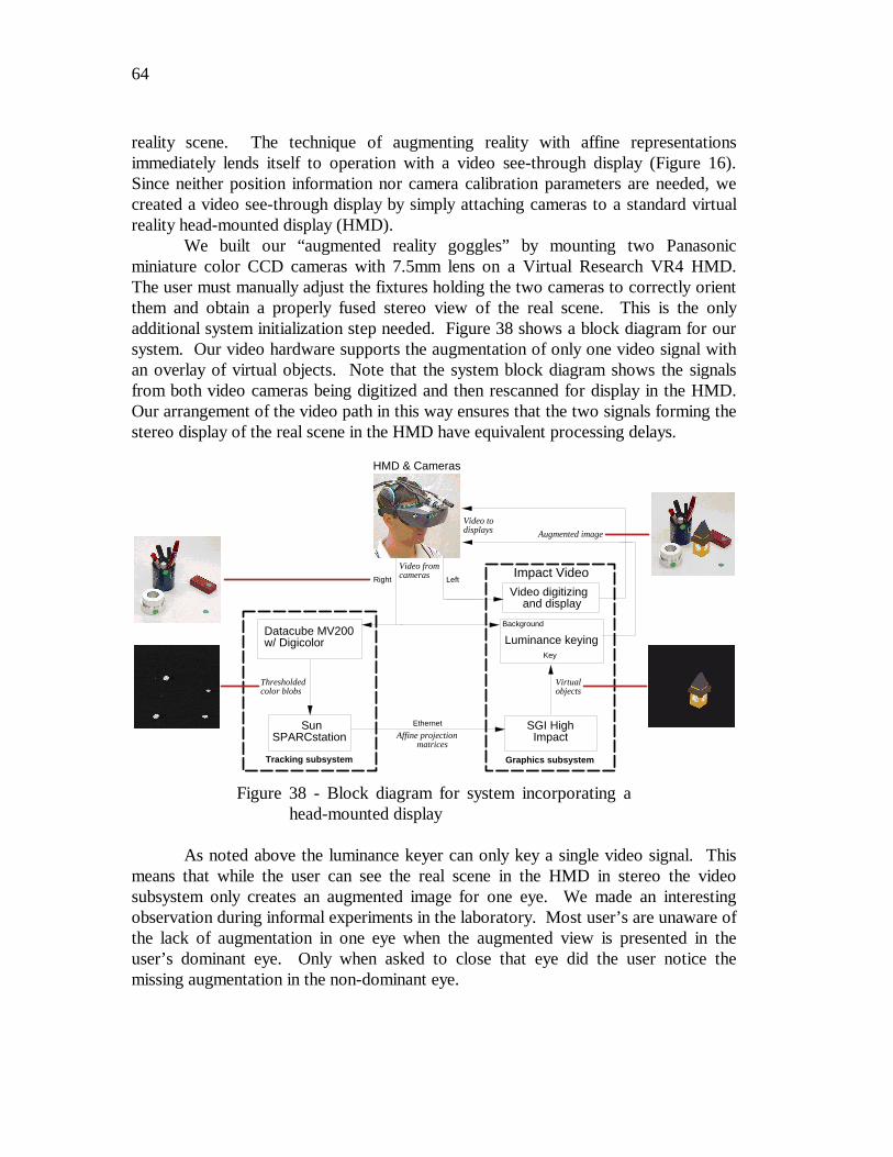
64
reality scene. The technique of augmenting reality with affine representationsimmediately lends itself to operation with a video see-through display (Figure 16).Since neither position information nor camera calibration parameters are needed, wecreated a video see-through display by simply attaching cameras to a standard virtualreality head-mounted display (HMD).
We built our “augmented reality goggles” by mounting two Panasonicminiature color CCD cameras with 7.5mm lens on a Virtual Research VR4 HMD.The user must manually adjust the fixtures holding the two cameras to correctly orientthem and obtain a properly fused stereo view of the real scene. This is the onlyadditional system initialization step needed. Figure 38 shows a block diagram for oursystem. Our video hardware supports the augmentation of only one video signal withan overlay of virtual objects. Note that the system block diagram shows the signalsfrom both video cameras being digitized and then rescanned for display in the HMD.Our arrangement of the video path in this way ensures that the two signals forming thestereo display of the real scene in the HMD have equivalent processing delays.
As noted above the luminance keyer can only key a single video signal. Thismeans that while the user can see the real scene in the HMD in stereo the videosubsystem only creates an augmented image for one eye. We made an interestingobservation during informal experiments in the laboratory. Most user’s are unaware ofthe lack of augmentation in one eye when the augmented view is presented in theuser’s dominant eye. Only when asked to close that eye did the user notice themissing augmentation in the non-dominant eye.
Graphics subsystem
Background
Key
Impact Video
SGI High Impact
Video digitizing and display
Tracking subsystem
Datacube MV200w/ Digicolor
SunSPARCstation
Ethernet
Luminance keying
Video todisplays
Video fromcameras Left
Affine projection matrices
HMD & Cameras
Thresholdedcolor blobs
Augmented image
Right
Virtualobjects
Figure 38 - Block diagram for system incorporating ahead-mounted display
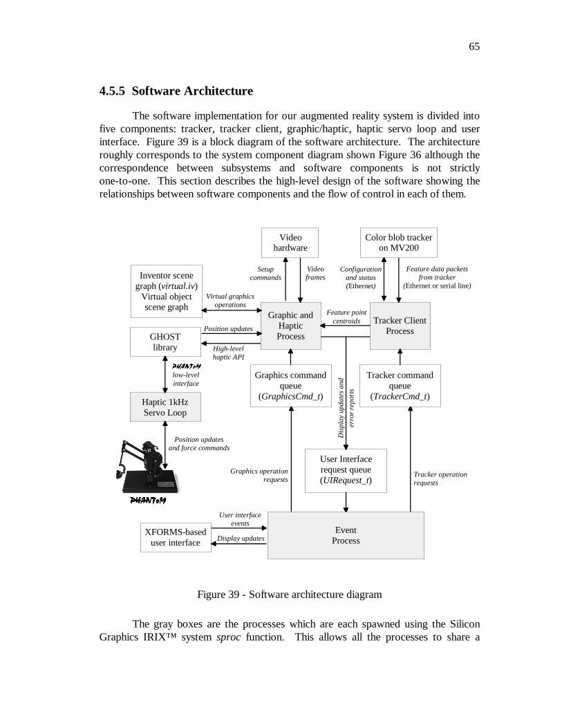
65
4.5.5 Software Architecture
The software implementation for our augmented reality system is divided intofive components: tracker, tracker client, graphic/haptic, haptic servo loop and userinterface. Figure 39 is a block diagram of the software architecture. The architectureroughly corresponds to the system component diagram shown Figure 36 although thecorrespondence between subsystems and software components is not strictlyone-to-one. This section describes the high-level design of the software showing therelationships between software components and the flow of control in each of them.
The gray boxes are the processes which are each spawned using the SiliconGraphics IRIX™ system sproc function. This allows all the processes to share a
3+$17R03+$17R0
Inventor scenegraph (virtual.iv)
Virtual objectscene graph
User Interfacerequest queue(UIRequest_t)
Tracker ClientProcess
Tracker commandqueue
(TrackerCmd_t)
Graphic andHapticProcess
Graphics commandqueue
(GraphicsCmd_t)
XFORMS-baseduser interface
User interfaceevents
Display updates
Feature data packetsfrom tracker
(Ethernet or serial line)
Position updatesand force commands
Haptic 1kHzServo Loop
GHOSTlibrary
3+$17R0
low-levelinterface
Feature pointcentroids
Virtual graphicsoperations
Dis
play
upd
ates
and
erro
r re
port
s
Tracker operationrequests
Graphics operationrequests
EventProcess
High-levelhaptic API
Position updates
Configurationand status(Ethernet)
Color blob trackeron MV200
Videoframes
Setupcommands
Videohardware
Figure 39 - Software architecture diagram
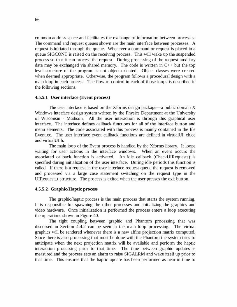
66
common address space and facilitates the exchange of information between processes.The command and request queues shown are the main interface between processes. Arequest is initiated through the queue. Whenever a command or request is placed in aqueue SIGCONT is raised on the receiving process. This will wake up the suspendedprocess so that it can process the request. During processing of the request auxiliarydata may be exchanged via shared memory. The code is written in C++ but the toplevel structure of the program is not object-oriented. Object classes were createdwhen deemed appropriate. Otherwise, the program follows a procedural design with amain loop in each process. The flow of control in each of those loops is described inthe following sections.
4.5.5.1 User interface (Event process)
The user interface is based on the Xforms design package—a public domain XWindows interface design system written by the Physics Department at the Universityof Wisconsin - Madison. All the user interaction is through this graphical userinterface. The interface defines callback functions for all of the interface button andmenu elements. The code associated with this process is mainly contained in the fileEvent.cc. The user interface event callback functions are defined in virtualUI_cb.ccand virtualUI.h.
The main loop of the Event process is handled by the Xforms library. It loopswaiting for user actions in the interface windows. When an event occurs theassociated callback function is activated. An idle callback (CheckUIRequests) isspecified during initialization of the user interface. During idle periods this function iscalled. If there is a request in the user interface request queue the request is removedand processed via a large case statement switching on the request type in theUIRequest_t structure. The process is exited when the user presses the exit button.
4.5.5.2 Graphic/Haptic process
The graphic/haptic process is the main process that starts the system running.It is responsible for spawning the other processes and initializing the graphics andvideo hardware. Once initialization is performed the process enters a loop executingthe operations shown in Figure 40.
The tight coupling between graphic and Phantom processing that wasdiscussed in Section 4.4.2 can be seen in the main loop processing. The virtualgraphics will be rendered whenever there is a new affine projection matrix computed.Since there is also processing that must be done with the Phantom the system tries toanticipate when the next projection matrix will be available and perform the hapticinteraction processing prior to that time. The time between graphic updates ismeasured and the process sets an alarm to raise SIGALRM and wake itself up prior tothat time. This ensures that the haptic update has been performed as near in time to
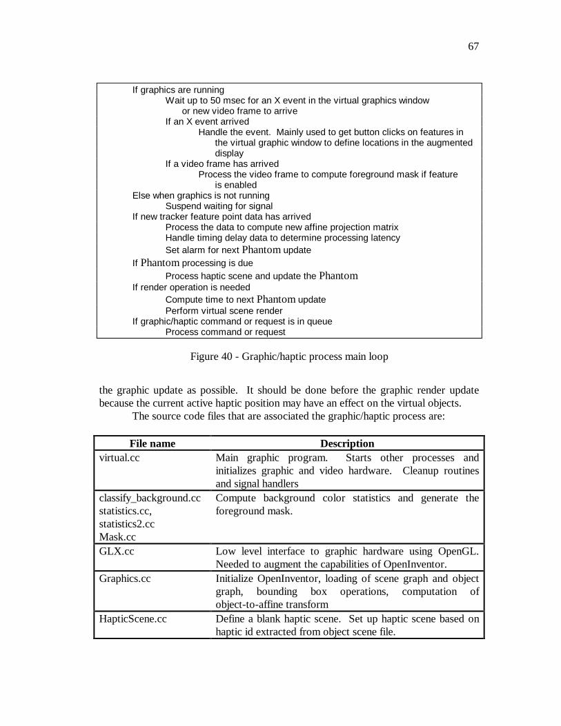
67
the graphic update as possible. It should be done before the graphic render updatebecause the current active haptic position may have an effect on the virtual objects.
The source code files that are associated the graphic/haptic process are:
File name Descriptionvirtual.cc Main graphic program. Starts other processes and
initializes graphic and video hardware. Cleanup routinesand signal handlers
classify_background.ccstatistics.cc,statistics2.ccMask.cc
Compute background color statistics and generate theforeground mask.
GLX.cc Low level interface to graphic hardware using OpenGL.Needed to augment the capabilities of OpenInventor.
Graphics.cc Initialize OpenInventor, loading of scene graph and objectgraph, bounding box operations, computation ofobject-to-affine transform
HapticScene.cc Define a blank haptic scene. Set up haptic scene based onhaptic id extracted from object scene file.
If graphics are runningWait up to 50 msec for an X event in the virtual graphics window
or new video frame to arriveIf an X event arrived
Handle the event. Mainly used to get button clicks on features inthe virtual graphic window to define locations in the augmenteddisplay
If a video frame has arrivedProcess the video frame to compute foreground mask if feature
is enabledElse when graphics is not running
Suspend waiting for signalIf new tracker feature point data has arrived
Process the data to compute new affine projection matrixHandle timing delay data to determine processing latencySet alarm for next Phantom update
If Phantom processing is dueProcess haptic scene and update the Phantom
If render operation is neededCompute time to next Phantom updatePerform virtual scene render
If graphic/haptic command or request is in queueProcess command or request
Figure 40 - Graphic/haptic process main loop
68
Phantom.cc Interfacing to GHOST library, processing Phantomcommands, computation of Phantom-to-affine transform
RegError.cc Perform dynamic registration error tests.TrackedPoints.cc Control display of feature centroid and affine basis, load
affine projection matrix into scene graphAlign.cc Compute graphics-to-video transformVideo.cc Setup, takedown and all interactions with the video
hardware
4.5.5.3 Tracker Client process
The tracker client process handles all of the interaction with the color blobtracker. Its main responsibilities are sending configuration and status requests to thetracker, processing the responses to those requests, and receiving the feature pointdata. Requests made to the tracker client include: start, stop and exit; send optionsand color segmentation masks; perform alignment operation; initialize the affine basis;and start/stop filtering or set the filter type. Operation of the main loop in this processis detailed in Figure 41. This figure shows the operation when the tracker transmitsfeature data on the serial channel.
In processing the feature point data this process performs the inter-frametracking operation using a simple nearest neighbor algorithm from the current positionto the previous position. There is opportunity here to improve on the inter-framecorrespondence. No cross-check is performed from the previous position to the newpositions. The tracker client also does the filtering and predictive estimation on the
If tracker is onWait on data arriving or receiving a signalIf serial channel data available
Process incoming feature dataIf socket data is available
While there is socket dataIf a receive error
Signal tracker deathElse
Process a reply from the tracker(alignment, rate update, start confirmation)
ElseSuspend waiting for SIGCONT
If tracker request is in queueExecute tracker function for the received command
Figure 41 - Tracker client process main loop
69
feature points if those options are active. The values reported to the graphic/hapticprocess are the filtered values.
The source files associated with the tracker client process are:
File names DescriptionTrackerClient.cc Main loop, functions for processing
tracker request, receiving data fromtracker and performing inter-framecorrespondence
AB.cc, ABC.cc α−β, α−β−γ filter codeABFiltering.cc, ABCFiltering.cc Glue between tracker client and filtersVSDFclass.cc Variable state dimension filter classVSDF.c Glue to Horatio library implementation of
VSDF
4.5.5.4 3+$17R0™ servo loop
The Phantom servo loop performs the low-level interfacing to the hapticdevice. This program is provided as part of the Phantom software distribution. It isstarted during initialization of the GHOST library. This program runs as a highpriority process under IRIX. It requests service at a 1 kHz rate and must be servicedat least at a 500 Hz rate or else a failsafe mechanism shuts down the motor drivers andterminates all force generation. As of the writing of this thesis, this process willrandomly hang the processor and/or reboot the machine. We were not able todetermine the exact cause of this problem. The manufacturers of the Phantom areaware of it and hopefully will resolve it with a future release of their software system.
4.5.5.5 Tracker
The color blob tracker is an ImageFlow program running partly on theDatacube MV200 system and on the host workstation. The operation of this programis discussed in Section 4.5.1. This process is spawned on the remote machinewhenever the user requests the system to start the tracker. The tracker client process,running on the local machine, handles all the interactions with the tracker. The twosystems communicate via Ethernet sockets using UDP datagrams. A compile timechoice allows the tracker to transmit feature point data on a serial line connection. Weimplemented the serial line connection because our experience showed that there wassignificant variability in transit times on the house Ethernet. The measured delay usingEthernet transmission, at times, was longer than on the slower serial line connection.
The Datacube program is locked to the video frame rate and is capable ofprocessing color blob data at 30Hz. Every time through the main loop the trackerprocesses a frame of video and checks the Ethernet socket for a request sent by the
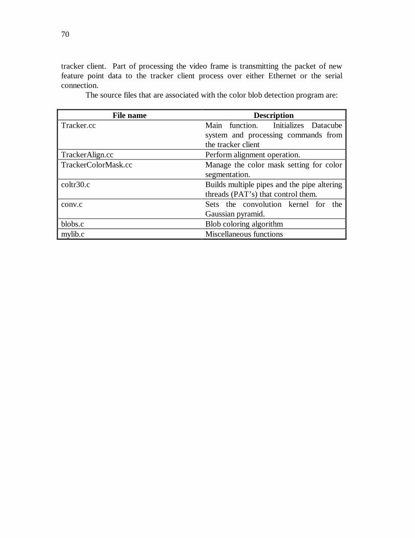
70
tracker client. Part of processing the video frame is transmitting the packet of newfeature point data to the tracker client process over either Ethernet or the serialconnection.
The source files that are associated with the color blob detection program are:
File name DescriptionTracker.cc Main function. Initializes Datacube
system and processing commands fromthe tracker client
TrackerAlign.cc Perform alignment operation.TrackerColorMask.cc Manage the color mask setting for color
segmentation.coltr30.c Builds multiple pipes and the pipe altering
threads (PAT’s) that control them.conv.c Sets the convolution kernel for the
Gaussian pyramid.blobs.c Blob coloring algorithmmylib.c Miscellaneous functions
71
5 Conclusions
5.1 Affine Representations: an Attractive Alternative
Augmenting reality using affine representations is an attractive alternative tothe previous methods used by augmented reality systems for registering the real andvirtual scenes. These previous methods (Feiner, MacIntyre et al. 1993b; Janin, Mizellet al. 1993; Rastogi, Milgram et al. 1995) mostly relied on explicit measurement of theposition of the viewer in the workspace. Methods (Grimson, Lozano-Perez et al.1994; Mellor 1995a; Neumann and Cho 1996) that did not require position sensing didrequire knowledge about the intrinsic parameters of the video camera viewing thescene or locations of fiducials placed in the image. The simplicity of the affinerepresentations method is very appealing, though the technique comes with a set ofnew requirements and limitations, namely, the requirement for real-time tracking offeatures, the weak perspective approximation, and the use of a non-Euclideanreference frame. This section discusses these requirements and limitations along withsuggestions for future work to address them.
5.1.1 Tracking as a source of registration errors
Our augmented reality system has two main sources for static and dynamicregistration errors. The entire technique rests on the ability to track multiple featurepoints over time in video images. The accuracy of the localization of the feature pointsin each video frame directly effects the definition of the common affine reference frameand in turn the placement of the virtual objects in the scene. This is particularly true inour system which is run using the minimum number of feature points. Some immunityto inaccurate feature point localization can be obtained at the expense of tracking morepoints in the scene. The tracker can influence both the static and dynamic registration.As has been mentioned in previous sections errors in the dynamic registration ofvirtual objects will give them an appearance of moving around in the scene. Virtualobjects lagging behind the rest of the scene motion is a common problem in allaugmented reality systems. Latencies, starting with the trackers, and then later addedon at any point in the system are a problem. Using 30Hz video input to the trackers
72
there is an immediate one-frame delay waiting for the video image to process.Executing the tracking algorithm adds an additional delay. In our system the colortracker adds approximately one additional frame delay.
Tracking has been studied in computer vision research for a long time. Manytracking algorithms are available that can be considered in place of the color blobtracking algorithm used in our system. Concentrating on the current system, there areareas that can be investigated for improvements. During experiments in the lab weobserved that the localization of a blob centroid varies ±1 pixel even with no motion inthe scene. This is caused by jitter in the color segmentation. One area that should bechecked to improve color segmentation is the shape of the window used in thesegmentation lookup table in the Datacube. Currently, this window has a sharp cutoffwhich can lead to jitter on the edges of the color field. Reworking this table so that itrepresents a window with sloped sides may help.
To improve the latency in the tracker subsystem tracking on fields at 60Hzshould be tried. The Digicolor module used for color acquisition on the Datacubesystem unfortunately can not be programmed to do field acquires. DatacubeCorporation was never able to provide information on how field rate acquisition couldbe performed. The assumption has been that it is not possible. An alternative that canbe considered is to switch to using the Cognachrome Vision System for color blobdetection. The Cognachrome, manufactured by Newton Labs, is capable of trackingcolor features of sizes similar to that used in our system at a 60Hz rate. This rate canbe maintained with at least 5 blobs in the scene. Tracking a larger number of blobswill result in decreased performance. The serial communication channel on theCognachrome can be interfaced using the serial input mode of the TrackerClient code.An additional benefit of the Cognachrome vision system is its $2500 cost which is afactor of ten lower than the cost of a Datacube system.
5.1.2 The affine approximation as a source of registration errors
The affine approximation is a known limitation in our system. Approximatingthe projective camera as an affine camera introduces errors. The severity of the errorscan be limited by operating within guidelines of not having feature points too far offaxis, keeping the focal length short compared to the average distance to the featurepoints in three-dimensional space and keeping the difference in depth between thenearest and farthest feature points short compared to the focal length of the lens. Wealso assume a perfect lens is in the video camera. A distortion-free lens is rarely thecase with most lens, at the least, exhibiting radial distortion to some degree. Lensdistortion incorrectly projects the feature points into the image plane and will produceerrors in the registration of virtual objects.
One benefit of the affine camera assumption is the simplicity of thecomputation of the projection matrix. If the simple affine formulation is kept then thelimits of the affine assumption will be present. One direction to pursue is using a
73
common projective representation instead (Faugeras 1992). A projectiverepresentation requires tracking a minimum of five feature points instead of the fourrequired for the affine representation. The affine approximation has been shown toyield more accurate results in structure-from-motion computations than a projectiverepresentation (Wiles and Brady 1996) when the large object-to-camera distancerequirement is not violated. This result warrants future investigation of Wiles andBrady’s combined appropriateness idea where the most appropriate camera model isselected for use. Lens distortion can be compensated for by calculating an appropriateimage warp (Mohr, Boufams et al. 1993) or estimating the distortion coefficients inconjunction with the tracking subsystem using a recursive variable state dimensionfilter (VSDF) (McLauchlan and Murray 1996).
5.1.3 Consequences of a non-Euclidean reference frame
The global affine coordinate system defines relative relationships between thecamera, real scene and virtual objects. This is useful for the purpose of registeringvirtual objects in the real scene but does have drawbacks that some researchersconsider significant (Azuma 1997; Koller, Klinker et al. 1997). Since we have onlyrelative relationship information generated at runtime there is no absolute referenceframe that is known apriori. No metric information about the real 3D world isobtained, which eliminates the possibility of placing virtual objects based onmeasurements in the real scene. The affine coordinates for locations inthree-dimensional space are not known until the common reference frame is defined atruntime. The virtual objects must be placed interactively after the global coordinatesystem has been determined via methods described in Section 4.1.5. An alternative isto place the virtual objects in the real scene using standard measurements and then atruntime calculate the transform of the coordinate system that defines the real scene tothe newly defined common affine reference frame. This is the technique employed bythe “one-step cheat” used by our current system. This “cheat” assumes that thebounding box for the virtual object is the affine coordinate system and thus the affinecoordinates are know without computation via the Affine Reconstruction Property(Section 4.1.3 ). For this to work, the feature points that define the affine basis pointsare placed so that they define a cube in three-dimensional real space.
The global affine coordinate system, in general, is not an orthonormal frame inspace. Operating in a non-orthonormal coordinate system has ramifications for somecomputations that must be performed. On the graphics subsystem our work hasdemonstrated that projection computations, z-buffer determination of visible surfaceand texture mapping can be performed within this affine representation. Otherrendering algorithms, such as lighting computations, that require metric information inthe form of measurement of angles, can not be performed in a straightforward mannerdirectly in affine space. For some augmented reality systems, such as those addressingapplications in the maintenance and military domains, this limitation on the rendering
74
of virtual objects is not a major issue. Additionally, how to perform the computationof dynamic behavior for the virtual objects in an affine coordinate system is an openquestion. The technique used in this system was to compute the dynamics in theEuclidean reference frame of the Phantom and then transform the virtual objects intothe global affine coordinate system for rendering. Likewise, real objects that interactwith any virtual objects were defined in the global coordinate system and thentransformed into the Euclidean Phantom coordinate system to determine the hapticinteractions
5.1.4 Feature tracking: the coign of the method
Augmenting reality with affine representations is limited by the accuracy,response and abilities of the tracking system. To date we have simplified our trackingproblem by limiting it to tracking high-contrast objects and easily segmented colorblobs. For each video image the tracking subsystem must compute a consistent globalcoordinate system. Tracking in a completely natural setting requires better trackingalgorithms or continued engineering of the scene to simplify the problem. We did notwant our work to mutate into a thesis on better trackers. Instead the features wereengineered to make the tracking process easily tractable. More capable trackingalgorithms are available in the literature and can be used within this system.
No results are presented in our work for the situation when the feature trackerdetects more or less than the required number of feature points. The current systemwill not generate an affine projection matrix if the tracker does not detect the correctnumber of features in an image. The system freezes the image of the virtual object atits last rendering if the correct number of feature points are not available. Additionalresearch work is needed to determine a method to generate a stable affine coordinatesystem when there are a variable number of feature points from one video frame to thenext. This variation may be due to:
• feature points being occluded for one or more frames,• a current feature point permanently disappearing, or• a new feature point appearing in the image.
One promising direction to look for a method to handle this feature point variation isthe Variable State Dimension Filter (VSDF) (McLauchlan and Murray 1995). Theformulation for this recursive Kalman filter allows a variable number of features. Italso enforces the affine structure by considering the feature points to be noisyobservations of the system state defined to be the affine projection matrix. Futurework in this area should also consider the research of Rodrigo Carceroni who haslooked at the most efficient methods to use the VSDF (Carceroni, Harman et al.1998). The results of his work shows that more accurate filtering of data points canbe obtained if very approximate camera calibration is available. The image feature
75
points are pre-multiplied by the inverse of the approximate camera calibrationtransform. This yields points defined in the 3D camera coordinate system. Thefiltering is applied to those points rather than the 2D image points that are filtered inour system. Factoring out the camera projection operation, even if only approximated,yields more accurate determination of the camera pose.
5.1.5 Class of applications best suited for affine augmented reality
Applications where there is little apriori knowledge about the scene will benefitmost from our method of augmenting reality using affine representations. Using noscene knowledge we define the global coordinate system simply by extracting featurepoints from the video images. The user interactively places virtual objects with respectto the global coordinate system at runtime. Also, because of the lack of metricinformation and limitations on the algorithms that can be directly used while renderingthe virtual scene ideal applications are those that do not require highly photorealisticvirtual objects to augment the real scene. For example, many applications from themilitary domain would match well with this technique. The scenario given for theVideo Surveillance and Monitoring project (Section 2.3.3) is one good application.Geometric information about the battlefield scene will rarely be available. The abilityto transfer position information from a reconnaissance aircraft to ground forcesthrough the correspondence of feature points is a very attractive solution.
In applications where apriori knowledge of the structure of the scene isavailable a technique that uses the scene information to directly compute a Euclideancamera position (Neumann and Cho 1996; State, Hirota et al. 1996) may be moreadvantageous. The additional metric information eliminates the need to positionvirtual objects and create the global affine definition of real objects at runtime. Inaddition, lighting calculations can be performed in a straightforward fashion. Oneflexibility that is lost, however, is the ability to vary the focal length of the videocamera that is viewing the real scene.
5.2 An Exercise in Software Engineering
An augmented reality system is a complex collection of multiple cooperatingcomponents. To build such a system requires a careful analysis of the systemrequirements. We built our augmented reality system using common real-time designtechniques. Often these software engineering considerations are ignored as part of aresearch project. One aspect of our work was to demonstrate that with carefulengineering it is possible to build a robust and reliable interactive augmented realitysystem. It is a system that is modular in design and can have new components addedto it without requiring a redesign of major components. We added the haptic
76
subsystem toward the end of the development cycle and we accomplished initialintegration in the relatively short period of two days because of the modular design.
5.2.1 Designing for minimum latency
The system implementation description in Section 4.5 highlighted the result ofmany of the design choices we made during the building of our augmented realitysystem. Latency (Section 4.3) has been seen to be a major concern for generating ahigh-fidelity augmented reality display. We designed the architecture around severalstandard techniques used for building complex software systems. The techniques usedin the architecture of the system that helped maximize its performance include:
• Multi-threaded architecture. There are five process threads in this system:feature tracker, tracker client, graphic/haptic application, haptic servo anduser interface. This architecture was decided upon to improve responsetime for the individual operations. Commands and requests are passedbetween threaded processes through queues. The alternative would havebeen a single monolithic loop architecture. Because there were severalactivities of the program that required waiting for data a loop architecturewould not give adequate service to all of the system components. Thiscomment is particularly true for the user interface functionality. With asingle threaded system processing of tracker data and the updating of theaffine projection matrix would be halted whenever user interface activitywas taking place. Or on the other side of the coin, the user interface wouldnot be able to respond at all to user actions if other components of thesystem were using all of the available processor cycles. The multi-threadeddesign prevents any one component from using all the processor cycles.The individual threads are full weight Unix processes sharing a commonaddress space. We performed an experiment to determine if improvedperformance could be obtained using lightweight POSIX compliantpthreads. We abandoned this direction was abandoned because the currentIRIX implementation of pthreads is not functioning correctly. When a newrelease of the OS is made the potential benefits of this change can bereconsidered.
• Event driven programs. When the program was originally built, weobserved CPU utilization close to 95%. This was in an early stage of thedesign before all of the graphics or any of the haptic operations were inplace. The user interface was very sluggish in response and adding morefunctionality seemed unlikely. These processes spent most of their timespinning on input. We adopted an event driven architecture to minimizeidle spiining. The tracker client, graphic/haptic and user interface were all
77
changed to trigger on events. One event that all three respond to is a newmessage in their respective command or request queues. The tracker clientalso waits on a select for new data from either the serial channel ornetwork socket that connects it to the feature tracker. With this designCPU load normally runs in the mid-20% range with the graphics objectstypically used and the haptic system not running. When the haptic servoloop is active the utilization is almost 90%. Not spending resources onwaiting processes provides the necessary processor cycles for all of theoperations especially the haptic servo loop. Only if the system was runningon a multi-processor machine could a non-event driven architecture beconsidered.
• Shared-memory data transfers. All processes running on the SiliconGraphics machine operate in a single address space having been createdusing the IRIX sproc system function. This permits easy sharing of databetween the threads. The architecture does use a limited number of globalvariables preferring instead to exchange information between threads usingthe command and request queues. This provides a clean interface and, forthe most part, a single interface point and method for all operations. Itmade adding new features an easy task. There was a standard set ofcoding operations for adding a new command or request. This eliminatedmost need for new design work to work new features into themulti-threaded architecture.
5.2.2 Incorporating haptic technology
The choices for haptic technology for an augmented or virtual reality systemare rather limited. Large scale body-suit exoskeletons can provide gross level forcesensations to the user. To handle finer manipulation tasks we choose a smaller scalehaptic system. The haptic servo loop is a large processor hog. It executes at a 1 kHzrate and will shut down if it is not serviced at a 500 Hz minimum rate. The GHOSTlibrary has the nice feature that it can read a VRML file as input. This could providethe ability to have the graphics and haptic scenes defined from the same source.Unfortunately, the R4000 processor available for our work can not render more than avery simplistic haptic scene. The standard clock tower that we often use as a virtualobject can not be haptically rendered without drastic trimming of its VRML file downto a set of no more than a handful of objects. Four or five cubes, spheres or othersimple shapes was the limit of the processor. Operation in a multi-processor machinecan almost be considered a requirement for using the Phantom� One processor alonewould be dedicated to running the haptic servo loop and other haptic functions.
The Phantom provides a very compelling sense of touching virtual objectsespecially when there is no conflict with the visual cues. In an augmented reality
78
environment conflicts do occur when proper occlusions between the real Phantom andthe virtual objects do not occur. The method we investigated with color backgrounddetection and masking of the video has promise. Improvement of this techniqueshould be considered for future work. There are many single block errors in the mask.Single block errors in the middle of the mask or along the edges could be handled byerosion and dilation morphological operations. We did not experiment with applyingmorphology as part of our work. Alternatively, a deformable snake defined usingnurbs—a graphic object with hardware rendering support—could be used to track thedetected foreground area. This would take care of both interior holes and jaggedcontours. Another direction we did not pursue is modeling the Phantom in thegraphics system and generating the occlusions from the graphics side instead of at theimage plane pixel level. Modeling the Phantom device has the disadvantage of nothandling occlusions generated by the user’s finger and hand. A combination of bothtechniques should be investigated.
5.3 A System that Works Surprisingly Well
The overall operation of our augmented reality system is very good—considering the simplicity of the underlying technique. This is despite some veryobvious flaws. The two flaws that seem the most glaring are: noisy feature trackingand a very rough method for computing the relationship between the haptic coordinatesystem and the common affine coordinate system. As we noted in Section 5.1.4, wesimplified the low-level tracking problem by selecting features that could be easilydetected in the video images. The color feature segmentation is visibly noisy and oneto two pixel jitter in the localization of features can be seen when the system isrunning. Any improvements made in feature tracking will directly help improveregistration accuracy. The system is also operating with the minimum number offeature points needed to define the common affine coordinate system. Using morethan the minimum number of points would provide some robustness to individualerrors in feature point localization. This would also allow the system to use thebenefits of the VSDF formulation mentioned in Section 5.1.4.
Computing the transform between haptic and affine coordinate systems isperformed by having the user move the end effector of the Phantom to the location ofthe four feature points defining the affine coordinate system. This is a very roughalignment operation. The active point of the end effector is in the middle of the user’sfinger. A compensation for this offset is added to the end effector location during thealignment operation but it is not a precise procedure. Despite this the registration ofthe graphic and haptic scene was never a source of problems for the user of the systemduring informal testing in the laboratory.
79
5.3.1 Qualitative comments
The generated augmented reality display is very convincing to the user. This isparticularly true when using the HMD setup (Figure 38). A small number of users didexperience problems generating a fused image of the real scene and for them themonitor-based system was better. Improvements in HMD technology and changingthe particular color cameras we used to newer models should improve that situation.Also, the method for fusing the video image of the real scene was to do a rotation ofthe two viewing cameras. This will generate a fused image at only a single workingdistance. Some users had trouble maintaining the stereo image because of changes indepth to the scene. They could not, for example, tilt their head up and view a moredistant lab area in stereo without adjusting the cameras. The more correct method tocreate a fused stereo image is to adjust the cameras to match interocular distance ofthe users pupils. This would require a bit more complex fixture to be used formounting the video cameras to the HMD. Current technology for the miniature“lipstick” video cameras does not provide for auto-focus. This will remain a limitationfor operating in an environment with widely varying distances in the work envelope.
The extent of realism of the display even with the monitor-based system can begauged by a common question asked by visitors viewing a lab demonstration of thesystem. Upon seeing the augmented image and getting a short description of thetechnique we use they will ask how the system can continue to operate when some ofthe feature points are being occluded by the virtual objects. The display is convincingenough that they begin to think that the video camera is seeing the augmented scene.This highlights how important occlusion is as a visual cue. Knowing that this is animportant cue it is not surprising that the realism of the augmented image decreasessignificantly when proper visual occlusions between virtual and real objects is notperformed. This is particularly true with Phantom operation. Without the smallvirtual fingertip (Section 4.4.4) to orient the user to the active position of the Phantomend effector in the scene using the haptic subsystem would be more difficult.
The relative simplicity of the haptic scene that can currently be rendered is alimitation to performing real world tasks with our system. Internally the graphics andhaptic scenes are separate data structures. Defining the interaction between theseobjects is a limitation of the system. The GHOST library provides an interface to thePhantom that is above the raw device level. Even with this, each one of the hapticdemonstrations that we created required hard coded sections of code to initialize thedemonstration and perform the interactions between the graphics image and thePhantom� A higher abstraction level is needed to increase the productivity of theprogrammer of these systems. This comment is not specific to an augmented realitysystem. It also applies to virtual reality systems that use this haptic subsystem.
80
5.3.2 Quantitative registration error studies
Our quantitative work centered around the primary challenge for augmentedreality, namely, improving the registration error. Using unfiltered feature pointlocalizations, the virtual objects do not remain visually fixed in the three-dimensionalspace. Small object jitter is present even when there is no motion in the system. Thisis due to noise in the color segmentation of the feature trackers. Section 4.5.1discusses potential sources for this noise. When there is motion the objects appear tobe moving from their fixed location in the scene. This motion is a very smooth motionand appears as a lag in that the object is behind its correct position as it moves.Filtering the feature points helps with the object jitter at the slight expense of responsetime. Usually making an assumption of constant velocity motion is not very effectivefor the non-linear motions that are present in this system. It was surprising that theassumption did work as well as it did and cut the registration error by a factor of 2.The reduction in error is offset by an increase in jerkiness of the virtual object motiondue to sensitivity of the first derivative operation to noise in the input. Depending onthe application it may actually be preferred to use unfiltered operation, if the smoothlags can be tolerated better than the more jerky object motion obtained with filtering.
Even with the best filtering and predication that could be applied, registrationerrors in our system are still easily detected by the viewer. The overall error iscomposed of both static errors, due to tracking error and violation of the affineapproximation, and dynamic errors, due mainly to system latencies. The affine cameraapproximation places an inherent lower bound on the registration error that can beachieved for a particular position in the workspace. To go beyond this the affineapproximation will need to be eliminated. Despite that, the method of augmentingreality using affine representations that we demonstrated is good enough for lesscritical applications. It will require more work if it is to be applied to any applicationin which misregistration can cause critical errors. Those applications, which wouldinclude most medical applications, can consider using affine representations only aftermore research has been done to improve the method’s overall accuracy.
5.4 The Elusive Augmented Reality Interface
The registration problem in augmented reality still has many areas forcontinuing research activities. This problem is a difficult one to solve and is likely toremain that way. Our work presented a novel approach for performing the coordinatesystem registration but it has not solved the problem because of several limitations.Future work is needed to extend this method so it can more closely match theperformance goals stated in Section 2.4. Particular shortcomings with respect to thesegoals and possible directions to find solutions include:
81
Desired Goal• operate in a completely natural
environment• reduce latencies• handle a variable number of
feature points• not be limited by the affine
approximation
Area requiring workÎ improved feature tracking
Î better filtering, faster hardwareÎ trackers robust to occlusions
Î projective representation
The fact that the system interacts with the real world adds an extra level ofdifficulty to the augmented reality problem. The number of researchers working inaugmented reality is small compared to, for example, the number of researchersworking in the closely associated virtual reality area. Considering the crucialregistration problem there is no recent quantitative work on errors. The work ofHolloway (Holloway 1997) still provides the only careful assessment of registrationerrors in an augmented reality system. Research activity is slowly moving from the labinto the real world, as seen in, the manufacturing application at Boeing and the imageguided surgery at MIT and Brigham and Woman’s Hospital. Progress in that directionwill continue as current research activities bear fruit. There still is lots of fertileground for exciting research work in augmented reality.
82
6 Summary, Contributions and FutureWork
The work we discussed in this thesis is in the area of augmented reality, whichis a relatively new field within the wider virtual reality research area. We discussed theperformance goals for an ideal augmented reality system. These goals place additionaldemands on an augmented reality system compared to a fully immersive virtual realitysystem. Our thesis work provides a new solution for the registration problem which isfaced by all augmented reality researchers and also shows that within that frameworkmany of the other performance goals can be achieved. This chapter summarizes thedemonstrated results and contributions of this work.
6.1 Demonstrated Results
Our work demonstrated that it is possible to create an augmented realitysystem, composed of multiple subsystems, that operates in real-time. Our systemcorrectly registers the virtual objects with the view of the real three-dimensional worldusing an affine representation for all objects. This registration is effected without anyknowledge of the intrinsic or extrinsic parameters of the video camera that is viewingthe scene. In addition, the system does not use any form of explicit position trackingto determine user motion within the workspace. We demonstrated the full integrationof a haptic subsystem with the other components in our augmented reality system.This haptic subsystem provides the user with the ability to touch virtual objects andfeel forces that accurately represent a natural interaction with the virtual object. Ourwork also demonstrated that within this framework visual and dynamic interactionsbetween virtual objects and real objects are correctly performed.
83
6.2 Contributions of this Thesis
6.2.1 Affine representations for augmented reality
The primary challenge for an augmented reality system is to determine theproper rendering and registration of the virtual objects that will be merged with theview of the real scene. This requires computation of the relationships betweenmultiple coordinate systems. Most augmented reality systems use methods thattransform these coordinate systems into a common 3D Euclidean frame relying onposition sensing, camera calibration and knowing the 3D locations of fiducial markersin the scene. By determining the relationship of the multiple coordinate systems to acommon non-Euclidean affine reference frame this system is able to determine thecamera pose with neither an explicit position measurement nor calibration of the videocamera viewing the scene. The registration problem is reduced to:
• real-time tracking of a set of four or more points that define a global affinecoordinate system,
• representing the virtual objects in the common affine coordinate system,and
• computing the projections of virtual points in each video image as linearcombinations of the projections of the affine basis points.
6.2.2 Realistic interactions with virtual objects
Using an affine representation to solve the registration problem, our work alsoshowed that an augmented reality system can provide realistic interactions with thevirtual objects that augment the user’s view of the real scene. These interactionsinclude correct visible occlusion of real objects by virtual ones and virtual objects byreal ones. It is not completely seamless, however, in that the dynamic interactions arenot computed in the affine coordinate system. Instead the interactions are performedin a Euclidean coordinate system and then transformed into the global affinecoordinate system for registration with the virtual graphic objects. Using the Phantomas a force output device, the realistic interactions with the virtual object included theability to:
• sense touching a virtual object in the correct location in space for itsplacement in the three-dimensional real scene,
• feel the “weight” of a virtual object when it is lifted,• feel surface texture on a virtual object, and
84
• feel the force of collisions of virtual objects with real objects.
6.2.3 Analysis of static and dynamic registration errors
We performed an analysis of the static and dynamic registration errors thatresult from using the method of affine representations in an augmented reality system.In regions in which the affine approximation was not violated, i.e. largecamera-to-object distances, the static reprojection errors were less than 3 pixels in aexperiment with camera distances ranging up to approximately 5 meters usingmanually tracked feature and test points (Figure 26, Figure 27). The errors increasedto a maximum of 15 pixels for closer distances as expected from the affine cameraapproximation. We measured dynamic registration errors for our method. Absolutequantitative measures are highly dependent on the motion used during the experiment.We recorded pixel errors in excess of 30 pixels for some rapid motions. In the onetest sequence we used for our experiments, the mean pixel error for the base system is11.9 pixels. Simple predictive filtering with forward estimates of three framesimproves the dynamic performance of the system by a factor of 2 to 3 (Figure 30).We see this improvement for the unfiltered case and when we applyα−β or α−β−γ filtering. This validated our qualitative assessment of the system andthe quantitative timing measurements that show a 90 msec. system latency. Theimprovement in performance does come with a loss in smoothness of virtual objectmotion, however.
6.2.4 System architecture
We have shown a system architecture demonstrating that an interactiveaugmented reality system can be built to run in real time. Our system is capable ofcorrectly registering the real and virtual images and giving the user the capability tointeract with the virtual objects in a natural manner. Our architecture is a contributionin that it can be used as a framework upon which to build future research activities inaugmented reality.
6.3 Future Work
There are many opportunities for continued research activity in augmentedreality. Many problems still remain unsolved. These opportunities exist in the topicarea in general and also more specifically in continuing work started by this thesis.Some of these future projects potentially include:
85
• Trackers - The tracker that we use can be improved in a number of ways.Work on the color segmentation would improve the jitter in localization offeature points. Switching to a faster tracker, such as the CognachromeVision System our department purchased, would improve system latencies.To move into a more natural setting will require the use of trackers that candetect and track natural features. In addition, robustness to feature pointocclusions will remove some of the restrictions that currently exist in oursystem. Handling feature point occlusions will most likely require operationwith more than the minimum number of points needed to define the basis.Having more features will improve the noise immunity due to theoverdetermined nature of the system.
• Affine representations - There are a number of limitations to the use ofaffine representations. Switching to a projective representation will allow forimproved operation in some regions of the workspace. A better approachmight be a hierarchy of representations along the lines of Wiles and Brady’s(1996) combined appropriateness. For some applications, it is worthinvestigating some recent results (Li, Brady et al. 1996; Carceroni, Harman etal. 1998). These results indicate that better estimation of motion parameterscan be obtained when some information, even if only approximate, isavailable for the intrinsic parameters of the camera and the scene structure.
• Haptic Interface - No pun intended, the surface has barely been scratchedon the use of a haptic interface in augmented reality. There are many moreareas for investigating interactions between virtual objects and real objects.How can this technology be incorporated into the application domainsmentioned in Chapter 2? Can the dynamics be performed directly in thecommon affine coordinate system rather than have to be converted from aEuclidean coordinate system? The foreground detection used to resolveocclusions can be improved. Currently, there are many single block holes inthe center of detected regions of motion. The contour of a foreground regionis also jagged. Morphological operations would clean up these errors inforeground detection or perhaps the contour can be defined by a deformablesnake.
We hope that some of these ideas for future work will spark a succession ofresearchers to continue the work in interactive augmented reality that was started withthis thesis.
86
Bibliography
Adelstein, B. D., E. R. Johnston and S. R. Ellis (1992), "A Testbed for CharacterizingDynamic Response of Virtual Environment Spatial Sensors," In Proceedings of 5thAnnual Symposium on User Interface Software and Technology, pages 15-21, 1992.
Ahlers, K., D. Breen, C. Crampton, E. Rose, M. Tuceryan, R. Whitaker and D. Greer(1994), "An Augmented Vision System for Industrial Applications," TechnicalReport ECRC-94-39, European Computer Industry Research Center (ECRC) 1994.
Ahlers, K. H., A. Kramer, D. E. Breen, P.-Y. Chevalier, C. Crampton, E. Rose, M.Tuceryan, R. T. Whitacker and D. Greer (1995), "Distributed Augmented Realityfor Collaborative Design Applications," Technical Report ECRC-95-05, EuropeanComputer Industry Research Center 1995.
Aukstakalnis, S. and D. Blatner (1992), Silicon Mirage - The Art and Science ofVirtual Reality, Berkeley, CA: Peachpit Press.
Azuma, R. (1993), “Tracking Requirements for Augmented Reality,”Communications of the ACM, 36(7):50-51.
Azuma, R. (1995), SIGGRAPH '95 Course Notes: A Survey of Augmented Reality,Los Angeles: Association for Computing Machinery.
Azuma, R. and G. Bishop (1994), "Improving static and dynamic registration in anoptical see-through hmd," In Proceedings SIGGRAPH '94, pages 197-204, 1994.
Azuma, R. and G. Bishop (1995), "A frequency-domain analysis of head-motionprediction," In Proceedings of SIGGRAPH 1995, pages 401-408, 1995.
Azuma, R. T. (1997), “A Survey of Augmented Reality,” Presence, 6(4):355-385.
Bajura, M. and U. Neumann (1995), “Dynamic Registration Correction in Video-Based Augmented Reality Systems,” IEEE Computer Graphics and Applications,15(5):52-60.
Balcisoy, S. and D. Thalman (1997), "Interaction between Real and Virtual Humans inAugmented Reality," In Proceedings of Computer Animation '97, pages 31-38, 5-6June 1997.
Ballard, D. H. and C. M. Brown (1982), Computer Vision, Englewood Cliffs:Prentice-Hall, Inc.
87
Barrett, E. B., M. H. Brill, N. N. Haag and P. M. Payton (1992), "Invariant LinearMethods in Photogrammetry and Model-Matching," In J. L. Mundy and A.Zisserman, editors, Geometric Invariance in Computer Vision, 277-292. Cambridge,MA: The MIT Press.
Betting, F., J. Feldmar, N. Ayache and F. Devernay (1995), "A New Framework forFusing Stereo Images with Volumetric Medical Images," In Proceedings ofComputer Vision, Virtual Reality, and Robotics in Medicine '95, pages 30-39, 1995.
Boufama, B., D. Weinshall and M. Werman (1994), "Shape from motion algorithms: acomparative analysis of scaled orthography and perspective," In Proceedings of theEuropean Conference on Computer Vision, pages 199-204, 1994.
Breen, D. (1995), Augmented Reality for Mechanical Maintenance and Repair.http://www.ecrc.de/research/uiandv/gsp/ECRCToday/mechrep.html (Current as ofJanuary 1998).
Brooks, F. P., M. Ouh-Young, J. J. Batter and P. J. Kilpatrick (1990), “ProjectGROPE - Haptic Displays for Scientific Visualization,” Computer Graphics,24(4):177-185.
Brown, C. M. (1994), "Tutorial on Filtering, Restoration, and State Estimation,"Technical Report TR534, Department of Computer Science, University ofRochester, September 1994.
Byrson, S. (1992), "Measurement and calibration of static distortion of position datafrom 3D trackers," In Proceedings SPIE Vol. 1669: Stereoscopic Displays andApplications III, pages 244-255, 1992.
Capin, T. K., H. Noser, D. Thalmann, I. S. Pandzic and N. M. Thalmann (1997),“Virtual Human Representation and Communication in VLNet,” IEEE ComputerGraphics and Applications, 17(2):42-53.
Carceroni, R. L., C. Harman, C. K. Eveland and C. M. Brown (1998), "Design andEvaluation of a System for Vision-Based Vehicle Convoying," Technical Report TR678, Department of Computer Science, University of Rochester, January 1998.
Caudell, T. P. (1994), "Introduction to Augmented Reality," In SPIE Proceedings Vol.2351: Telemanipulator and Telepresence Technologies, pages 272-281, Novmeber1994.
Cavallaro, R. (1997), “The FoxTrax Hockey Puck Tracking System,” IEEEComputer Graphics and Applications, 17(2):6-12.
Corby, N. R., Jr. and C. A. Nafis (1994), "Augmented reality telemanipulation systemfor nuclear reactor inspection," In Proceedings SPIE Vol. 2351: Telemanipulationand Telepresence Technologies, pages 360-365, 31 October -1 November 1994.
88
Dinsmore, M., N. Langrana, G. Burdea and J. Ladeji (1997), "Virtual Reality TrainingSimulation for Palpation of Subsurface Tumors," In Proceedings of the IEEE 1997Virtual Reality Annual International Symposium, pages 54-60, 1-5 March 1997.
Drascic, D., J. J. Grodski, P. Milgram, K. Ruffo, P. Wong and S. Zhai (1993),"ARGOS: A Display System for Augmenting Reality," In Proceedings of InterCHI93 Conference on Human Factors in Computing Systems, page 521, 1993.
Durlach, N. I. and A. S. Mavor, Eds. (1995), Virtual Reality: Scientific andTechological Challenges. Washington, D.C.: National Academy Press.
Ellis, S. R., F. Bréant and B. Menges (1997), "Factors Influencing OperatorInteraction with Virtual Objects Viewed via Head-mounted See-through Displays:viewing conditions and rendering latency," In Proceedings of the IEEE 1997 VirtualReality Annual International Symposium, pages 138-145, 1-5 March 1997.
Ettinger, G., E. Grimson, T. Kapur, R. Kikinis, M. Leventon, T. Lozano-Perez, J. P.Mellor, S. Wells and S. White (1998), Image Guided Surgery Home Page.http://www.ai.mit.edu/projects/vision-surgery/surgery_home_page.html (Current asof January 1998).
Fabiani, L., G. Burdea, N. Langrana and D. Gomez (1996), "Human interface usingthe Rutgers Master II force feedback interface," In Proceedings of the IEEE 1996Virtual Reality Annual International Symposium, pages 54-59, March 1996.
Faugeras, O. D. (1992), "What can be seen in three dimensions with an uncalibratedstereo rig?," In Proceedings of Second Euopean Conference on Computer Vision,pages 563-578, 1992.
Feiner, S., B. MacIntyre, M. Haupt and E. Solomon (1993a), "Windows on theWorld: 2D Windows for 3D Augmented Reality," In Proceedings of ACMSymposium on User Interface Software and Technology, pages 145-155, 1993a.
Feiner, S., B. MacIntyre and D. Seligmann (1993b), “Knowledge-Based AugmentedReality,” Communications of the ACM, 36(7):53-62.
Feiner, S., B. MacIntyre and D. Seligmann (1995), KARMA.http://www.cs.columbia.edu/graphics/projects/karma (Current as of January 1998).
Foley, J. D., A. van Dam, S. K. Feiner and J. F. Hughes (1990), Computer GraphicsPrinciples and Practice, Reading, MA: Addison-Wesley Publishing Co.
Fraunhofer Institute for Computer Graphics (1997), IGD A4 - Augmented Reality.http://www.ecrc.de/staff/gudrun/ar/london/Lond.html (Current as of January 1998).
Gibbs, S. (1995), GMD Digital Media Lab: Virtual Studio.http://viswiz.gmd.de/DML/vst/vst.html (Current as of January 1998).
Grimson, W. E. L., G. J. Ettinger, S. J. White, P. L. Gleason, T. Lozano-Perez, W. M.W. III and R. Kikinis (1995), "Evaluating and Validating an Automated Registration
89
System for Enhanced Reality Visualization in Surgery," In Proceedings of ComputerVision, Virtual Reality, and Robotics in Medicine '95, pages 3-12, 1995.
Grimson, W. E. L., T. Lozano-Perez, W. M. W. III, G. J. Ettinger, S. J. White and R.Kikinis (1994), "An Automated Registration Method for Frameless Stereotaxy,Image Guided Surgery, and Enhanced Reality Visulatization," In Proceedings IEEEConference on Computer Vision and Pattern Recognition, pages 430-436, 1994.
Hoff, W. A., K. Nguyen and T. Lyon (1996), "Computer Vision-Based RegistrationTechniques for Augmented Reality," In Proceedings SPIE Vol. 2904: IntelligentRobots and Computer Vision XV: Algorithms, Techniques, Active Vision, andMaterials Handling, pages 538-548, November 1996.
Holloway, R. L. (1997), “Registration Error Analysis for Augmented Reality,”Presence, 6(4):413-432.
Janin, A. L., D. W. Mizell and T. P. Caudell (1993), "Calibration of head-mounteddisplays for augmented reality applications," In Proceedings IEEE Virtual RealityAnnual International Symposium '93, pages 246-255, 1993.
Jannin, P., A. Bouliou, J. M. Scarabin, C. Barillot and J. Luber (1997), "Visualmatching between real and virtual images in image guided neurosurgery," InProceedings SPIE Vol. 3031: Medical Imaging 1997: Image Display, pages 518-526, 23-25 February 1997.
Jebara, T., C. Eyster, J. Weaver, T. Starner and A. Pentland (1997), "Stochasticks:Augmenting the Billiards Experience with Probabilistic Vision and WearableComputers," Technical Report TR-439, MIT Media Lab, October 1997.
Kalata, P. R. (1984), “The Tracking Index: A Generalized Parameter for α−β and α−β−γ Target Trackers,” IEEE Transactions on Aerospace and Electronic Systems,AES-20(2):174-182.
Kanade, T. (1996), Z-Key: A New Method for Creating Virtual Reality.http://www.cs.cmu.edu/afs/cs/project/stereo-machine/www/z-key.html (Current asof April 1996).
Kim, W. S., P. S. Schenker, A. K. Bajczy, S. Leake and S. Ollendorf (1993), "AnAdvanced Operator Interface Design with Preview/Predictive Displays for Ground-Controlled Space Telerobotic Servicing," In Proceedings of SPIE Vol. 2057:Telemanipulator Technology and Space Telerobotics, pages 96-107, 1993.
Koenderink, J. J. and A. J. van Doorn (1991), “Affine Structure from Motion,”Journal of the Optical Society of America A, 8(2):377-385.
Koller, D., G. Klinker, E. Rose, D. Breen, R. Whitaker and M. Tuceryan (1997),"Real-time Vision-Based Camera Tracking for Augmented Reality Applications," InProceedings of the Symposium on Virtual Reality Software and Technology, pages87-94, September 1997.
90
Kutulakos, K. N. and J. R. Vallino (1996a), "Affine Object Representations forCalibration-Free Augmented Reality," In Proceedings of 1996 IEEE Virtual RealityAnnual International Symposium, pages 25-36, 1996a.
Kutulakos, K. N. and J. R. Vallino (1996b), "Non-Euclidean Object Representationsfor Calibration-free Video Overlay," In Proceedings Object Representation inComputer Vision II. ECCV '96 International Workshop., pages 381-401, April1996b.
Li, F., M. Brady and C. Wiles (1996), "Fast Computation of the Fundamental Matrixfor an Active Stereo Vision System," In Proceedings of the Fourth EuropeanConference on Computer Vision, pages 157-166, 1996.
Lorensen, W., H. Cline, C. Nafis, R. Kikinis, D. Altobelli and L. Gleason (1993),"Enhancing Reality in the Operating Room," In Proceedings of the 1993 IEEEVisualization Conference, pages 410-415, 1993.
Manhart, P. K., R. J. Malcolm and J. G. Frazee (1993), "'Augeye': A Compact, SolidSchmidt Relay for Helmet Mounted Displays," In Proceedings 1993 IEEE VirtualReality Annual International Symposium, pages 234-245, 1993.
Mark, W. R., S. C. Randolph, M. Finch, J. M. V. Verth and R. M. T. II (1996),"Adding Force Feedback to Graphics Systems: Issues and Solutions," InProceedings of the 1996 Symposium on Interactive 3D Graphics, pages 447-452,1996.
McLauchlan, P. F. and D. W. Murray (1995), "A unifying framework for structure andmotion recovery from image sequences," In Proceedings of the 5th IEEEInternational Conference on Computer Vision, pages 314-320, 1995.
McLauchlan, P. F. and D. W. Murray (1996), “Active Camera Calibration for a Head-Eye Platform Using the Variable State-Dimension Filter,” IEEE Transactions onPattern Analysis and Machine Intelligence, 18(1):15-21.
Mellor, J. P. (1995a), Enhanced Reality Visualization in a Surgical Environment,Masters thesis, AI Lab, Massachusetts Institute of Technology.
Mellor, J. P. (1995b), "Realtime Camera Calibration for Enhanced Reality," InProceedings of Computer Vision, Virtual Reality, and Robotics in Medicine '95(CVRMed '95), pages 471-475, 1995b.
Metzger, P. J. (1993), "Adding Reality to the Virtual," In Proceedings of the IEEE1993 Virtual Reality Annual International Symposium, pages 7-13, 1993.
Milgram, P. and F. Kishino (1994), “A Taxonomy of Mixed Reality Visual Displays,”IEICE Transactions on Information Systems, E77-D(12):1321-1329.
Milgram, P., H. Takemura, A. Utsumi and F. Kishino (1994), "Augmented Reality: AClass of Displays on the Reality-Virutality Continuum," In Proceedings SPIE Vol.2351: Telemanipulator and Telepresence Technologies, pages 282-292, 1994.
91
Milgram, P., S. Zhai, D. Drascic and J. J. Grodski (1993), "Applications ofAugmented Reality for Human-Robot Communications," In Proceedings of 1993IEEE/RSJ International Conference on Intelligent Robots and Systems, pages 1467-1476, 1993.
Mine, M. R., F. P. Brooks and C. H. Sequin (1997), "Moving objects in space:exploiting proprioception in virtual-environment interaction," In Proceedings of 24thInternational Conference on Computer Graphics and Interactive Techniques, pages19-26, August 1997.
Mohr, R., B. Boufams and P. Brand (1993), "Accurate projective reconstruction," InJ. L. Mundy, A. Zisserman and D. Forsyth, editors, Applications of Invariance inComputer Vision, 257-276: Springer-Verlag.
National Association of Broadcasters (1994), "Princeton Electronic BillboardDevelops "Virtual Arena" Technology for Television,", National Association ofBroadcasters, April 18, 1994 1994.
Neumann, U. and Y. Cho (1996), "A Self-Tracking Augmented Reality System," InProceedings of ACM Symposium on Virtual Reality Software and Technology,pages 109-115, July 1996.
Neumann, U. and Y. Cho (1997), Video See-through Self-tracking Augmented Reality(STAR). http://tracker.usc.edu/~ykcho/star.html (Current as of January 1998).
Newman, W. and R. Sproull (1973), Principles of Interactive Computer Graphics,New York: McGraw-Hill.
Patel, V. V., M. W. Vannier, J. L. Marsh and L.-J. Lo (1996), “Assessing craniofacialsurgical simulation,” IEEE Computer Graphics and Applications, 16(1):46-54.
Polhemus Corporation (1996), Polhemus Trackers. http://www.together.com/trackres/ourprod.html (Current as of 21 April 1996).
Pyros, G. G. and B. N. Goren (1995), “Desktop Motion Image Processing forEpisodic Television,” Advanced Imaging, 10(7):30-34.
Rastogi, A., P. Milgram and J. J. Grodski (1995), Augmented Telerobotic Control: avisual interface for unstructured environments. http://vered.rose.utoronto.ca/people/anu_dir/papers/atc/atcDND.html (Current as of January 1998).
Roland, J. P., R. L. Holloway and H. Fuchs (1994), "A comparision of optical andvideo see-through head-mounted displays," In Proceedings SPIE Vol. 2351:Telemanipulator and Telepresence Technologies, pages 293-307, 1994.
Rosen, J. M., D. R. Laub, S. D. Pieper, A. M. Mecinski, H. Soltanian, M. A.McKenna, D. Chen, S. L. Delp, J. P. Loan and C. Basdogan (1996), "Virtual Realityand Medicine: From Training Systems to Performing Machines," In Proceedings ofthe IEEE 1996 Virtual Reality Annual International Symposium, pages 5-13, 1996.
92
Shapiro, L., A. Zisserman and M. Brady (1995), “3D Motion Recovery via AffineEpipolar Geometry,” International Journal of Computer Vision, 16(2):147-182.
Shashua, A. (1993), "Projective Depth: A Geometric Invariant for 3D Reconstructionfrom Two Perspective/Orthographic Views and For Visual Recognition," InProceedings 1993 IEEE International Conference on Computer Vision, pages 583-590, 1993.
Sims, D. (1994), “New Realities in Aircraft Design and Manufacture,” IEEEComputer Graphics and Applications, 14(2):91.
Srinivasan, M. A. and C. Basdogan (1997), “Haptics in virtual environments:taxonomy, research status, and challenges,” Computers & Graphics, 21(4):393-404.
State, A., D. T. Chen, C. Tector, A. Brandt, H. Chen, R. Ohbuchi, M. Bajura and H.Fuchs (1994), "Case Study: Observing a Volume Rendered Fetus within a PregnantPatient," In Proceedings of the 1994 IEEE Visualization Conference, pages 364-368, 1994.
State, A., G. Hirota, D. T. Chen, W. F. Garrett and M. A. Livingston (1996),"Superior augmented reality registration by integrating landmark tracking andmagnetic tracking," In Proceedings of the ACM SIGGRAPH Conference onComputer Graphics, pages 429-438, 1996.
Sutherland, I. E. (1963), "Sketchpad: A Man-Machine Graphical CommunicationSystem," In Proceedings of Spring Joint Computer Conference 1963.
Taylor, R. H., J. Funda, L. Joskowicz, A. D. Kalvin, S. H. Gomory, A. P. Gueziec andL. M. G. Brown (1996), “An overview of computer integrated surgery at the IBMThomas J. Watson Research Center,” IBM Journal of Research and Development,40(2):163-183.
Thompson, W. B. and J. L. Mundy (1987), "Three-dimensional model matching froman unconstrained viewpoint," In Proceedings of the IEEE 1987 Robotics andAutomation Conference, pages 208-220, 1987.
Tomasi, C. and T. Kanade (1992), “Shape and motion from image streams underorthography: A factorization method,” International Journal of Computer Vision,9(2):137-154.
Tsai, R. Y. (1987), “A versatile camera calibration technique for high-accuracy 3Dmachine vision metrology using off-the-shelf TV cameras and lenses,” IEEETransactions of Robotics and Automation, RA-3(4):323-344.
Tuceryan, M., D. S. Greer, R. T. Whitaker, D. E. Breen, C. Crampton, E. Rose and K.H. Ahlers (1995), “Calibration Requirements and Procedures for a Monitor-BasedAugmented Reality System,” IEEE Transactions on Visualization and ComputerGraphics, 1(3):255-273.
93
Uenohara, M. and T. Kanade (1995), "Vision-Based Object Registration for Real-Time Image Overlay," In N. Ayache, editor, Computer Vision, Virtual Reality andRobotics in Medicine: CVRMed '95, 14-22. Berlin: Springer-Verlag.
Ullman, S. and R. Basri (1991), “Recognition by Linear Combinations of Models,”IEEE Transactions on Pattern Analysis and Machine Intelligence, 13(10):992-1006.
UNC - Chapel Hill (1995), Augmented Reality. http://www.cs.unc.edu/Research/graphics/graphics.html (Current as of January 1998).
UNC - Chapel Hill (1997), UNC Ultrasound Research. http://www.cs.unc.edu/~us/(Current as of January 1998).
Urban, E. C. (1995), “The Information Warrior,” IEEE Spectrum, 32(11):66-70.
Ware, C., K. Arthur and K. S. Booth (1993), "Fish Tank Virtual Reality," InProceedings of InterCHI 93 Conference on Human Factors in Computing Systems,pages 37-42, 1993.
Welch, R. B. (1978), Perceptual Modification: Adapting to Altered SensoryEnvironments, New York: Academic Press.
Wiles, C. and M. Brady (1996), "On the Appropriateness of Camera Models," InProceedings of the Fourth European Conference on Computer Vision, pages 228-237, 1996.
Wloka, M. M. and B. G. Anderson (1995), "Resolving Occlusion in AugmentedReality," In Proceedings 1995 Symposium on Interactive 3D Graphics, pages 5-12,1995.
Wren, C. R., A. Azarbayejani, T. Darrell and A. P. Pentland (1997), “Pfinder: real-time tracking of the human body,” IEEE Transactions on Pattern Analysis andMachine Intelligence, 19(7):780-785.
Yokokohji, Y., R. L. Hollis and T. Kanade (1996), ""What You can See Is What Youcan Feel" - Development of a Visual/Haptic Interface to Virtual Environments," InProceedings of the IEEE 1996 Virtual Reality Annual International Symposium,pages 46-53, 30 March - 3 April 1996.
Ziegler, R. (1996), "Haptic Displays - How we can feel Virtual Environments," InProceedings SPIE Vol. 2949: Imaging Sciences and Display Technologies, pages221-232, 7-10 October 1996.
Ziegler, R., C. Brandt, C. Kunstmann, W. Müller and H. Werkhäuser (1997), "HapticDisplay of the VR Arthroscopy Training Simulator," In Proceedings SPIE Vol.3012: Stereoscopic Displays and Virtual Reality Systems IV, pages 479-486, 11-14February 1997.

94
Zikan, K., W. D. Curtis, H. A. Sowizral and A. L. Janin (1994), "A note on dynamicsof human head motions and on predictive filtering of head-set orientations," InProceedings of SPIE Vol. 2351: Telemanipulator and Telepresence Technologies,pages 328-336, 1994.
Zorpette, G. (1994), “An eye-popping summer,” IEEE Spectrum, 31(10):19-22.


![Madame Bovary on the Holodeck: Immersive Interactive ... · Immersive Interactive ... [Multimedia Information Systems] Artificial, Augmented and Virtual Reality - Virtual Reality](https://img.pdfslide.net/doc/110x75/5b0dbe807f8b9a2f788e329e/madame-bovary-on-the-holodeck-immersive-interactive-interactive-multimedia.jpg)


![ARCord: Visually Augmented Interactive Cords for Mobile ... · of body-worn devices including smartwatches, interactive jewelry & accessories [14], and high-quality augmented reality](https://img.pdfslide.net/doc/110x75/5f5b5a41a7a7e67bd067f515/arcord-visually-augmented-interactive-cords-for-mobile-of-body-worn-devices.jpg)