Embed Size (px)
Citation preview

Interactive Fire Alarm System
User GuideLoop viewer tool, LoopViewer
Protecting life, environment and property... P-ASAFE-LV/FE, Rev. A, 033105

COPYRIGHT ©
This publication, or partsthereof, may not be reproducedin any form, by any method, forany purpose.
Autronica Fire and Security ASand its subsidaries assume noreponsibility for any errors thatmay appear in the publication,or for damages arising from theinformation in it. No informationin this publication should beregarded as a warranty made byAutronica Fire and Security. Theinformation in this publicationmay be updated without notice.
Product names mentioned inthis publication may betrademarks. They are used onlyfor identification.

Error! Style not defined.
Error! Unknown switch argument., AutroSafe Interactive Fire Alarm System, Release 3, P-ASAFE-LV/FE, Rev. A, 033105, Autronica Fire and Security AS
Page 1
Table of Contents
1. Introduction.....................................................................31.1 About the Handbook ....................................................................31.2 The Reader .................................................................................31.3 Reference Documentation............................................................3
2. General Description ........................................................4
3. Setting up the System.....................................................63.1 Minimum PC-requirements...........................................................63.2 Installing the Software..................................................................63.3 Installing the Hardware.................................................................7
3.3.1 Overview ...........................................................................73.3.2 Cable Connections Overview in Interface Unit WAS-2000.....83.3.3 Connecting the Loop Cable to the Loop Driver Module in
WAS-2000 .........................................................................93.3.4 Cable Connections to an AutroSafe Operating Panel ............10
3.4 Starting LoopViewer.....................................................................10
4. Operating the Tool ..........................................................114.1 Overview.....................................................................................114.2 The ”Topology” Window ...............................................................12
4.2.1 Select Loop Driver..............................................................134.2.2 The START Button ............................................................144.2.3 The STOP Button...............................................................144.2.4 The Report Button ..............................................................154.2.5 Comfail Bargraph ...............................................................164.2.6 Status Bar..........................................................................164.2.7 Static Loop Unit Information ................................................164.2.8 Notifications Button.............................................................17
5. List of Symbols ...............................................................18
6. Examples of Special Topologies....................................196.1 Example 1: Break in Loop Wiring ..................................................196.2 Ex. 2: Multiple Branch-off (Star-connection)...................................206.3 Ex. 3: Inadequate Interpretation of Loop Topology .........................21
7. Reader’s Comments........................................................25

Error! Style not defined.
Error! Unknown switch argument., AutroSafe Interactive Fire Alarm System, Release 3, P-ASAFE-LV/FE, Rev. A, 033105, Autronica Fire and Security AS
Page 2

Error! Style not defined.
Error! Unknown switch argument., AutroSafe Interactive Fire Alarm System, Release 3, P-ASAFE-LV/FE, Rev. A, 033105, Autronica Fire and Security AS
Page 3
1. Introduction
1.1 About the HandbookThis handbook is intended to provide all necessary information for theoperation of the loop viewer tool, LoopViewer .
1.2 The ReaderThe handbook is intended to be used by Autronica Fire and Securityservice and technical personnel who are responsible for theinstallation and verification of detection loops.
1.3 Reference DocumentationIn addition to this manual, Autronica Fire and Security offers thefollowing documentation:
Handbook Item NumberSystem Specification P-ASAFE/XEInstallation Handbook, Fire Alarm Control Panel (BS-310/320) / Controller (BC-320) P-ASAFE-FA/DEInstallation Handbook, Operator Panel (BS-330) P-ASAFE-OP/DEInstallation Handbook, Repeater Panel (BU-320) / Information Panel (BV-320) P-ASAFE-RI/DEInstallation Handbook, Battery Cabinet (SY-310) P-ASAFE-BC/DECommissioning Handbook P-ASAFE/EEOperator’s Handbook, Fire Alarm Control Panel (BS-310/320) / Operator Panel (BS-330) P-ASAFE-FO/FEOperator's Handbook, Repeater Panel (BU-320) P-ASAFE-FB/FEOperator's Handbook, Information Panel (BV-320) P-ASAFE-IN/FEShortform User Guide P-ASAFE-SH/LEShortform Configuration Guide (for the AutroSafe Demo Board) P-ASAFE-SH/VEWall Chart P-ASAFE-WE/LXWall Chart P-ASAFE-CH/LXMenu Structure P-ASAFE/MXUser Guide, Loop Simulator Tool P-ASAFE-LS/FEUser Guide, Loop Calculator Tool P-ASAFE-LC/FEUser Guide, Merge Tool P-ASAFE-MT/FEUser Guide, Power Calculator Sheet P-ASAFE-PC/FE

Error! Style not defined.
Error! Unknown switch argument., AutroSafe Interactive Fire Alarm System, Release 3, P-ASAFE-LV/FE, Rev. A, 033105, Autronica Fire and Security AS
Page 4
2. General Description
The LoopViewer is a PC-based installation and marketing tool,running under Windows 95, 98, NT, 2000, XP. The LoopViewerincludes the following main features:
• Graphical TOPOLOGY view of all loop units in one loop. Presentsloop with branch off (1 level), loop break position, loop short-circuitpostion, and individual graphical symbols for all AutroSafe loopunits.
• Measuring facilities for finding a loops total resistance, currentconsumption and voltage drop.
• Possibility to find breaks in loop wire, both in positive and negativewire.
• Possibility to make loop files for import to the Configuration Tool. The LoopViewer can be run when connected directly to an AutroSafeoperating panel (Fire Alarm Control Panel BS-310/320, BC-320), orstandalone connected to the loop by means of an external interfaceunit, WAS-2000, available from Autronica Fire and Security AS.

Error! Style not defined.
Error! Unknown switch argument., AutroSafe Interactive Fire Alarm System, Release 3, P-ASAFE-LV/FE, Rev. A, 033105, Autronica Fire and Security AS
Page 5

Error! Style not defined.
Error! Unknown switch argument., AutroSafe Interactive Fire Alarm System, Release 3, P-ASAFE-LV/FE, Rev. A, 033105, Autronica Fire and Security AS
Page 6
3. Setting up the System
3.1 Minimum PC-requirements• Intel 486 DX 100MHz or higher• Windows 95, 98, NT, 2000, XP• Serial COM-port (COM1 to COM4)• 32Mb of RAM is recommended• Monitor with resolution of 1024 x 768 HiColor (16 bit ), is
recommended• Mouse or other pointing device
3.2 Installing the SoftwareThe software consists of only one single file: LoopViewer.exe.
• Copy this file to any folder/directory you want.• Create a “shortcut” to this file by dragging the file from windows
explorer to your desktop. An icon with some building will appear onyour desktop if success.
• Make sure your computer monitor is setup with a resolution of1024x768 HiColor (16 bit).
• To start LoopViewer, double-click the icon.

Error! Style not defined.
Error! Unknown switch argument., AutroSafe Interactive Fire Alarm System, Release 3, P-ASAFE-LV/FE, Rev. A, 033105, Autronica Fire and Security AS
Page 7
3.3 Installing the Hardware
3.3.1 Overview
The LoopViewer can be run when connected to an AutroSafeoperating panel (Fire Alarm Control Panel BS-310/320, BC-320), orstandalone connected to the loop with an external interface unit.
One of the serial ports on the computer must be connected to theCommunication Module (BSL-310) in the operating panel or to anexternal interface unit (both alternatives are shown below).
The external Interface Unit WAS-2000 consists of 1 Power ModuleBSS-310, 1 Communication Module BSL-310, and 1 Loop DriverModule BSD-310 (batteries and charger unit also included). Thesemodules are always included in an operating panel.
If connection to the loop is through the WAS-2000 it will be the onlyloop available. If connection is through a panel, the loop drivermodules BSD-310 / BSD-311 may be selected from the LoopViewerprogram. Default selection will be to the first loop driver module.
For detailed information on cable connections, consult the followingchapters.
Loop Driver Module in Fire AlarmControl Panel BS-310/320
PRESS HERETRYKK HERKNUS GLASSET
BREAK GLASS
DetectorI/O Unit Manual Call Point
BN- 320BRANNALARM
Tilpasningsenhet
FIRE ALARMInterface unit
Nr.
No.
BN- 320BRANNALARM
Tilpasningsenhet
FIRE ALARMInterface unit
Nr.
No.
220V AC
WAS-2000
Power
Fire Brigade Msg
Fire Vent Activated
Fire Ext Activated
0
ALARM
?
C
987
654
321
Silence Buzzer
Silence Sounders
Reset
More Alarms
Prewarning
Early Warning
System Fault
Function Disabled
Test
Fault
Self Verify
General Alarm
PRESS HERETRYKK HERKNUS GLASSET
BREAK GLASS
DetectorI/O Unit Manual Call Point
BN- 320BRANNALARM
Tilpasningsenhet
FIRE ALARMInterface unit
Nr.
No.
BN- 320BRANNALARM
Tilpasningsenhet
FIRE ALARMInterface unit
Nr.
No.

Error! Style not defined.
Error! Unknown switch argument., AutroSafe Interactive Fire Alarm System, Release 3, P-ASAFE-LV/FE, Rev. A, 033105, Autronica Fire and Security AS
Page 8
3.3.2 Cable Connections Overview in Interface Unit WAS-2000
Consult the drawing below, and do the following:• Available with the WAS-2000 there is a ribbon cable XJA-027 with
a 9-pin Dsub and a ribbon cable connector.• Connect the 9-pin Dsub connector to one of the serial ports (COM1
or COM4) on your computer and the flat ribbon connector to theBSL-310 communication module in the WAS-2000.
• Connect the WAS-2000 Interface unit to the 220V AC mains outlet.
Note:If a battery is installed, it must be disconnected when not in use, toavoid discharge.
24V DC Out
In
1
2
4
5
6
3
+
-
+
-
Detector
3
1 2
3
2 1
3
1 2
BSD-310
+ Ø+ Ø- Ø- Ø
Cableto PCCom-port **
24VDC POWER SUPPLY
(fuse inside)
Ø Ø Ø Ø Ø Ø
24VDC
BSS-310 BSL-310 BSD-310 / BSD-311
Al_Com+- outDetector loop+- in
Mains 220VAC + 24 V - BATTERY (*optional)

Error! Style not defined.
Error! Unknown switch argument., AutroSafe Interactive Fire Alarm System, Release 3, P-ASAFE-LV/FE, Rev. A, 033105, Autronica Fire and Security AS
Page 9
3.3.3 Connecting the Loop Cable to the Loop Driver Module in WAS-2000
Screw Terminal no.on Loop Driver Module
BSD-310
Signal
1 OUT +
2 OUT -
3 CHASSIS
4 IN +
5 IN -
6 CHASSIS
The Loop Module BSD-310 / BSD-311 must be connected to the loopyou want to communicate with.
Input
Output
24V DC Out
In
1
2
4
5
6
3
+
-
+
-
Detector
3
1 2
3
2 1
3
1 2
BSD-310
1 - IN2 - OUT3 + COMMON4 - LED

Error! Style not defined.
Error! Unknown switch argument., AutroSafe Interactive Fire Alarm System, Release 3, P-ASAFE-LV/FE, Rev. A, 033105, Autronica Fire and Security AS
Page 10
3.3.4 Cable Connections to an AutroSafe Operating Panel
If the LoopViewer is to be connected to the Communication ModuleBSL-310 inside an operating panel, a flat ribbon cable XJA-027 mustbe used.(Available from Autronica Fire and Security AS.) A 9-pin Dsubconnector for the COM-port on your computer, and a ribbon cableconnector for the panel. The ribbon cable that is already connected tothe Communication Module BSL-310 inside the panel, must bedisconnected (see figure) before the other end of the cable from thecomputer can be connected.
Note:To avoid activating the internal buzzer when disconnecting the ribboncable from the Communication Module BSL-310, turn the power OFFbefore disconnecting the ribbon cable. When you have connected theexternal ribbon cable from the computer, turn the power ON.
All power connections to the Power Module BSS-310 are alreadydone. The Loop Driver Modules BSD-310 / BSD-311 are alreadyconnected to the loops.
3.4 Starting LoopViewer
• Start the LoopViewer by double clicking at the shortcut you madein chapter 3.2
You will be asked which serial port to use (COM1 to COM4), and thenthe software is running.

Error! Style not defined.
Error! Unknown switch argument., AutroSafe Interactive Fire Alarm System, Release 3, P-ASAFE-LV/FE, Rev. A, 033105, Autronica Fire and Security AS
Page 11
4. Operating the Tool
4.1 OverviewThe LoopViewer starts by asking you for the COM-port to which theXJA-027 cable has been connected.
Select the COM-port and then the OK button.
The LoopViewer will then check for a correct connection to a BSL-310in a WAS-2000 or inside a panel and show this window for a fewseconds:
Then the LoopViewer will automatically open the Topology window asshown below.If you do not see this AutroSafe logo you probably do not have acorrect connection from your computer to the BSL-310Communication Module. If the XJA-027 cable seems to be OK, youalso have to check that the COM-port selected is the one where theXJA-027 cable is physically connected. One other possibility is thatthe WAS-2000 or the panel has not been powered up.

Error! Style not defined.
Error! Unknown switch argument., AutroSafe Interactive Fire Alarm System, Release 3, P-ASAFE-LV/FE, Rev. A, 033105, Autronica Fire and Security AS
Page 12
4.2 The ”Topology” WindowThe Topology window is the window that will give you access to allfunctions and will show a graphical view of the AutroSafe loop. Youwill need to do a ‘Topology scan’ before the other functions areavailable. HIT

Error! Style not defined.
Error! Unknown switch argument., AutroSafe Interactive Fire Alarm System, Release 3, P-ASAFE-LV/FE, Rev. A, 033105, Autronica Fire and Security AS
Page 13
4.2.1 Select Loop Driver
The Select Loop Driver button allows you to select the loop drivermodule (BSD-310 / BSD-311) for the loop to be looked at. By default,loop driver 1 (LD1) is selected, but the user can select any othermodule. Only loop drivers of the type BSD-310 or BSD-311 will becorrectly handled by the LoopViewer although all modules found willbe shown in the Select Loop Driver window.
Pressing the Search Loop Drivers button forces the LoopViewer tofind all loop drivers.
If there are several loop drivers or other modules available, the usermust select the one to which the actual loop is connected.
When pressing the START button (see next chapter) a graphicalpresentation of the selected module will appear. The examples belowshow two different presentations.
Example: A Loop Driver BSD-310 has been selected
Example: Communication Module BSL-310 hasbeen selected
As shown in the example, the LoopViewer is not able topresent the topology for the modules BSL/BSB/BSJ-310.
Error! Style not defined.
Error! Unknown switch argument., AutroSafe Interactive Fire Alarm System, Release 3, P-ASAFE-LV/FE, Rev. A, 033105, Autronica Fire and Security AS
Page 14
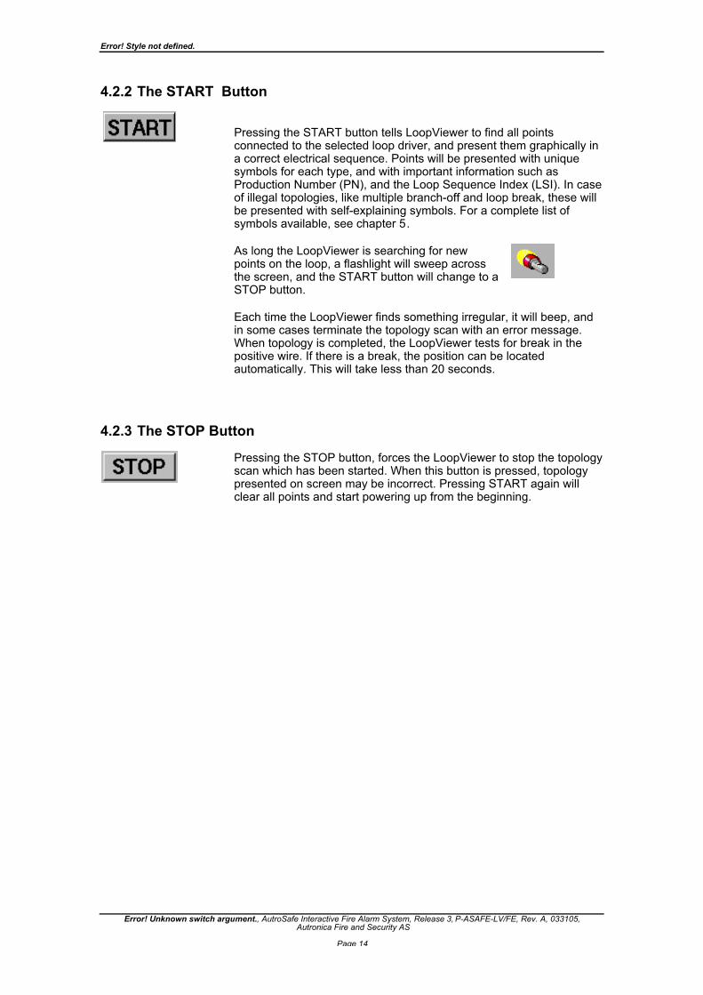
4.2.2 The START Button
Pressing the START button tells LoopViewer to find all pointsconnected to the selected loop driver, and present them graphically ina correct electrical sequence. Points will be presented with uniquesymbols for each type, and with important information such asProduction Number (PN), and the Loop Sequence Index (LSI). In caseof illegal topologies, like multiple branch-off and loop break, these willbe presented with self-explaining symbols. For a complete list ofsymbols available, see chapter 5.
As long the LoopViewer is searching for newpoints on the loop, a flashlight will sweep acrossthe screen, and the START button will change to aSTOP button.
Each time the LoopViewer finds something irregular, it will beep, andin some cases terminate the topology scan with an error message.When topology is completed, the LoopViewer tests for break in thepositive wire. If there is a break, the position can be locatedautomatically. This will take less than 20 seconds.
4.2.3 The STOP Button
Pressing the STOP button, forces the LoopViewer to stop the topologyscan which has been started. When this button is pressed, topologypresented on screen may be incorrect. Pressing START again willclear all points and start powering up from the beginning.

Error! Style not defined.
Error! Unknown switch argument., AutroSafe Interactive Fire Alarm System, Release 3, P-ASAFE-LV/FE, Rev. A, 033105, Autronica Fire and Security AS
Page 15
4.2.4 The Report Button
Pressing the Report button allows you to generate a report for theselected loop. The report provides useful information, as shown on thereport example below.
It is possible to sort by Loop Sequence Indexes (LSI) or by type.
Clicking the "Make Configuration" button, allows you to generate aCSV file, which the AutroSafe Configuration Tool can import andconvert to AutroConfig format. This means you can tell theconfiguration tool what is on the loop, and let the configuration toolgenerate the configuration for this loop.

Error! Style not defined.
Error! Unknown switch argument., AutroSafe Interactive Fire Alarm System, Release 3, P-ASAFE-LV/FE, Rev. A, 033105, Autronica Fire and Security AS
Page 16
4.2.5 Comfail Bargraph
The Comfail status field presents the number ofALCOM communication failures per time unit. Thedefault sample period is 5 seconds.
4.2.6 Status Bar
A status bar at the bottom of the screen gives the followinginformation:
4.2.7 Static Loop Unit Information
When pointing on a loop unit in the topology window, a hand symbolwill appear, and static information related to this unit will be shown inthe field to the right.
LoopViewer statusGives the status of the LoopViewer atthe moment, and tells if input isexpected from the user.
Earthfailure on + and -wire(if present).
Static Information
Points:The totalnumber ofpoints isshown.
States the chosenLoop Driver module.

Error! Style not defined.
Error! Unknown switch argument., AutroSafe Interactive Fire Alarm System, Release 3, P-ASAFE-LV/FE, Rev. A, 033105, Autronica Fire and Security AS
Page 17
4.2.8 Notifications Button
The LoopViewer Notification Log is a popup window where allimportant messages / notifications from AutroSafe components willappear. The log will contain time stamps, and the log may be copiedand pasted into text editors for documentation or storing.
The Notification log (separate window that describes received events)will for this version not be set in front (as the selected window) everytime the LoopViewer receives an event. So if you close the window itmay not appear by it self on the next event. It can then be displayedby pushing the “Notification” button.

Error! Style not defined.
Error! Unknown switch argument., AutroSafe Interactive Fire Alarm System, Release 3, P-ASAFE-LV/FE, Rev. A, 033105, Autronica Fire and Security AS
Page 18
5. List of Symbols
List of all known symbols presented in topology window
Loop driver (P0)
Heat detector (BD-200/300/500)
Optical smoke detector (BH-200/300/500)
Multisensor (smoke&heat) detector (BH-220/320/520)
Manual callpoint (BF-200/300/500)
Addressable sounder (BBR-200, BBR-110)
Input / Output unit (BN-300,BN-310,BN-320,BN-201)
Topology ERROR
Probably caused by multiple branch-off, which isillegal. By double-clicking this symbol, a list of thepoints causing the branch will appear.
Loop Break
Indicates a break in the loop wire at indicatedposition
Loop Short-circuit
Indicates a short-circuit on the loop wire.
Loop Communication Error
Indicates a communication error.

Error! Style not defined.
Error! Unknown switch argument., AutroSafe Interactive Fire Alarm System, Release 3, P-ASAFE-LV/FE, Rev. A, 033105, Autronica Fire and Security AS
Page 19
6. Examples of Special Topologies
6.1 Example 1: Break in Loop WiringIn this example, the LoopViewer couldn’t find the ‘IN’ side of the Loopdriver, when powering up from the ‘OUT’ side. Since it can’t be knownwhich of the points LSI-4 or LSI-3.1 is the main loop, and which is thebranch, the LoopViewer presents a break symbol after both. TheLoopViewer will then power up the loop from the ‘IN’ side, and find thepoints on the other side of the break. Note that if there is more thanone break in the main loop, there may be several points missing in theloop topology presentation.

Error! Style not defined.
Error! Unknown switch argument., AutroSafe Interactive Fire Alarm System, Release 3, P-ASAFE-LV/FE, Rev. A, 033105, Autronica Fire and Security AS
Page 20
6.2 Ex. 2: Multiple Branch-off (Star-connection)In this example, the LoopViewer has given a warning between LSI 19and 21. This is to indicate that when closing LSI 19’s switch, morethan 2 new points where powered up. The LoopViewer cannot presentmore than 3 points in a star-connection, and since more than 1branch-off is illegal in an AutroSafe system, this warning is given.
So in this case, LSI-21, LSI-19.1 and LSI-20.1 are connected to thesame point, LSI-19. A possible solution to this problem, would be toconnect branch 19.1 to 19.2 between the manual callpoint (LSI18) andthe Multisensor (LS19).
Note that the LoopViewer cannot present more than 3 points in a star-connection. If there were more than LSI-21, LSI-19.1 and LSI-20connected to LSI-19, these additional would not be presented in thetopology window.

Error! Style not defined.
Error! Unknown switch argument., AutroSafe Interactive Fire Alarm System, Release 3, P-ASAFE-LV/FE, Rev. A, 033105, Autronica Fire and Security AS
Page 21
6.3 Ex. 3: Inadequate Interpretation of Loop TopologyIn certain situations, The LoopViewer may not give a totally correctpresentation of the loop topology. Several factors may affect theinterpretation of the loop topology, for example, whether a pointbelongs to the main loop or a branch-off, which point is registered firstduring power up, if there is an illegal branch-off, etc.
In this example, the LoopViewer informs you that there is one multiplebranch-off, and that there is a break in the loop wire. Note that this isactually not the fact, but a result of how the program may interpret theloop in such a situation.
When more than one point powers up at the same time, theLoopViewer has to guess which one belongs to the ‘main loop’, andwhich one is a branch off.
If the LoopViewer comes to a break in the loop wire, it will swap thelast assumption (main loop and branch-off), and continue. But if theLoopViewer makes a bad guess, and the branch chosen to be themain loop contains a new branch-off (illegal), the LoopViewer hasproblems.
Then the last assumption is verified to be true, and the topologypresented will be difficult to understand. The presentation is notwrong, but it may be very inadequate.
In the example above, the LoopViewer guesses that LSI-2 is on themain loop, and LSI-1.1 is the branch off. This is actually not true, LSI-1.1 is the main loop.

Error! Style not defined.
Error! Unknown switch argument., AutroSafe Interactive Fire Alarm System, Release 3, P-ASAFE-LV/FE, Rev. A, 033105, Autronica Fire and Security AS
Page 22
Normally, the LoopViewer will find out that it has made a mistake, andswitch the last guess made. In this example, however, the LoopViewermeets a branch after LSI-2, and since a branch in a branch-off isillegal, it assumes that this is still on the main loop, and that the lastguess (LSI-2) was correct. But as it can’t find more points on what itthinks is the main loop, it assumes the loop has a break at this point.
So because of the illegal branch LSI-2.1, the LoopViewer is mislead tobelieve it is still on the main loop.
As the assumed branch 1.1 is powered up, two points get powered upat the same time at the end of the branch. This is illegal (no branch-offin branch-off’s), so the LoopViewer has to place a warning symbolthere, and stop presenting the rest of the branch.
The two points where actually the last point in what should have beenthe main loop, and the ‘IN’ side of the loop driver (closed loop).
Below, the correct topology is presented, as the LoopViewer wouldhave presented it if it hadn’t guessed wrong in the case of LSI-2, or ifthe illegal multiple branch-off didn’t affect the presentation.

Error! Style not defined.
Error! Unknown switch argument., AutroSafe Interactive Fire Alarm System, Release 3, P-ASAFE-LV/FE, Rev. A, 033105, Autronica Fire and Security AS
Page 23


Error! Style not defined.
Error! Unknown switch argument., AutroSafe Interactive Fire Alarm System, Release 3, P-ASAFE-LV/FE, Rev. A, 033105,Autronica Fire and Security AS
7. Reader’s CommentsPlease help us to improve the quality of our documentation by returning your comments on thismanual:
Title: User Guide,Loop Viewer Tool, LV-2000AutroSafe Interactive Fire Alarm System, Release 3
Ref. No.: P-ASAFE-LV/FE, Rev. A, 033105
Your information on any inaccuracies or omissions (with page reference):
Please turn the page

Error! Style not defined.
Error! Unknown switch argument., AutroSafe Interactive Fire Alarm System, Release 3, P-ASAFE-LV/FE, Rev. A, 033105,Autronica Fire and Security AS
Suggestions for improvements
Thank you! We will investigate your comments promptly.
Would you like a written reply? q Yes q No
Name: ------------------------------------------------------------------------------------------------------------
Title: ------------------------------------------------------------------------------------------------------------
Company: ------------------------------------------------------------------------------------------------------------
Address: ------------------------------------------------------------------------------------------------------------
------------------------------------------------------------------------------------------------------------
------------------------------------------------------------------------------------------------------------
Telephone: ------------------------------------------------------------------------------------------------------------
Fax: ------------------------------------------------------------------------------------------------------------
Date: ---------------------------------------------------------------------------------
Please send this form to: Autronica Fire and Security AS
N-7483 Trondheim
Norway
Tel: + 47 73 58 25 00
Fax: + 47 73 58 25 01

Error! Style not defined.
Error! Unknown switch argument., AutroSafe Interactive Fire Alarm System, Release 3, P-ASAFE-LV/FE, Rev. A, 033105,Autronica Fire and Security AS

Autronica Fire and Security AS is an international company, based in Trondheim,Norway and has a world-wide sales and service network. For more than 40 yearsAutronica’s monitoring systems have been saving lives and preventing catastrophes onland and at sea. Autronica Fire and Security’s most important business area is firedetection & security. Autronica Fire and Security stands for preservation ofenvironment, life and property.
Quality AssuranceStringent control throughout Autronica Fire and Security assures the excellence of ourproducts and services. Our quality system conforms to the Quality System StandardNS-EN ISO 9001, and is valid for the following product and service ranges: marketing,sales, design, development, manufacturing, installation and servicing of:
• fire alarm and security systems• petrochemical, oil and gas instrumentation systems for monitoring and control
In the interest of product improvement, Autronica Fire and Security reserves the rightto alter specifications according to current rules and regulations.
Autronica Fire and Security ASFire and Security, Trondheim, Norway. Phone: + 47 73 58 25 00, fax: + 47 73 58 25 01.Oil & Gas, Stavanger, Norway. Phone: + 47 51 84 09 00, fax: + 47 51 84 09 99.Autronica Industrial Ltd., Watford, United Kingdom. Phone: 1923 23 37 68, fax: 1923 22 55 77.


![v µ }v - Autronica Firepartner.autronicafire.com/fileshare/filArkivRoot/produkt/pdf/... · /v µ }v µ }W}]v , îììUííòrWr, îììl/' U ÀX UîìíòrìñrìôUµ }v] &] v](https://img.pdfslide.net/doc/110x75/5aaee88b7f8b9a190d8caf3e/v-v-autronica-v-wv-urwr-l-u-x-urru-v-v-wleruxu-xl.jpg)