Embed Size (px)
Citation preview

Technical Report Documentation Page
1. Report No. 2. Government Accession No. 3. Recipient's Catalog No.
FHW A!fX-9811291-1
4. Title and Subtitle 5. Report Date
January 1998
INTERACTIVE GRAPIDCS INTERSECTION DESIGN 6. Performing Organization Code SYSTEM (IGIDS) TRAINING MANUAL
7. Author(s) 8. Performing Organization Report No.
Thomas W. Rioux, Robert Inman, Randy B. Machemehl, Research Report 1291-1 and Clyde E. Lee
9. Performing Organization Name and Address 10. Work Unit No. (TRAIS)
Center for Transportation Research The University of Texas at Austin 3208 Red River, Suite 200 11. Contract or Grant No.
Austin, TX 78705-2650 0-1291
12. Sponsoring Agency Name and Address 13. Type of Report and Period Covered
Texas Department of Transportation Research Report (9/96 8/97) Construction/Research Section P.O. Box 5080 14. Sponsoring Agency Code
Austin, TX 78763-5080
15. Supplementary Notes
Project conducted in cooperation with the Federal Highway Administration.
16. Abstract
The Interactive Graphics Intersection Design System (IGIDS), a software package that operates on personal computers and workstations, has been developed to assist engineers in the analysis and design of isolated, at-grade intersections. This report serves as the training manual for the application of this intersection design software.
17. KeyWords 18. Distribution Statement
Intersection design, Interactive Graphics Intersection No restrictions. This document is available to the public through the Design System (IGIDS) National Technical Information Service, Springfield, Virginia 22161.
19. Security Classif. (of report) 20. Security Classif. (of this page) 21. No. of pages 22. Price
Unclass:if'ted Unclassified 120
Form DOT F 1700.7 (8-72) Reproduction of completed page authorized

INTERACTIVE GRAPIDCS INTERSECTION DESIGN SYSTEM (IGIDS) TRAINING MANUAL
by
Thomas W. Rioux Robert F. Inman
Randy B. Machemehl and
Clyde E. Lee
Research Report Number 1291-1
Research Project 0-1291 Interactive Graphics Intersection Design System (IGIDS)
Conducted for the
TEXAS DEPARTMENT OF TRANSPORTATION
in cooperation with the
U. S. Department of Transportation Federal Highway Administration
by the
CENTER FOR TRANSPORTATION RESEARCH Bureau of Engineering Research
THE UNIVERSITY OF TEXAS AT AUSTIN
January 1998

11

This report was prepared in cooperation with the Texas Department of Transportation and the U.S. Department of Transportation, Federal Highway Administration.
ACKNOWLEDGMENTS
The authors express appreciation for the guidance provided by the TxDOT Project Director, H. Wickes (TRF), and by the Project Monitoring Committee, which included J. Barron (Waco), M. Emery (Tyler), B. Gilley (Lubbock), J. Kelly (Lubbock), C. Slacum (Lufkin), and E. Sanchez (El Paso).
DISCLAIMERS
The contents of this report reflect the views of the authors, who are responsible for the facts and the accuracy of the data presented herein. The contents do not necessarily reflect the official views or policies of the Federal Highway Administration or the Texas Department of Transportation. This report does not constitute a standard, specification, or regulation.
There was no invention or discovery conceived or first actually reduced to practice in the course of or under this contract, including any art, method, process, machine, manufacture, design or composition of matter, or any new and useful improvement thereof, or any variety of plant, which is or may be patentable under the patent laws of the United States of America or any foreign country.
NOT INTENDED FOR CONSTRUCTION, BIDDING, OR PERMIT PURPOSES
Randy B. Machemehl, P.E. (Texas No. 41921) Research Supervisor
iii

iv

TABLE OF CONTENTS
Overview of IGIDS ............................................................................................................. 1 Caution .............................................................................................................................. 11 Introduction of MicroStation 95 ........................................................................................ 13 Simple Example ................................................................................................................ 27 Vehicle Turn Templates .................................................................................................... 31 Horizontal Sight Distance ................................................................................................. 37 Vertical Sight Distance ...................................................................................................... 43 Pretimed Traffic Signal and HCM Chapter 9 Analysis ..................................................... 51 NEMA Traffic Signal ........................................................................................................ 59 Texas Model for Intersection Traffic ................................................................................ 71 Signal Operations Analysis Package (SOAP) ................................................................... 75 Striping and Traffic Inventory Report ............................................................................... 79 Add Leg ............................................................................................................................. 89 References ......................................................................................................................... 97 Appendix ......................................................................................................................... 101
v

vi

OVERVIEW OF THE INTERACTIVE GRAPHICS INTERSECTION DESIGN SYSTEM (IGIDS)
Intersection design is a complex process that involves many different skills. Elements of transportation planning, traffic engineering, and geometric design contribute to the process of designing the most practicable facility for intersection traffic. Traditionally, the design engineer has relied upon the application of manual - or sometimes computer-aided- procedures to determine the most appropriate alternative that satisfies the objectives. The process involves geometric layout, traffic analysis, channelization, selection and placement of traffic control devices, timing of traffic signals, lighting, drainage, fuel-consumption evaluation, pollution analysis, cost estimating, and other engineering functions that are eventually reduced to practice in a set of plans and specifications. Virtually all the engineering and analysis procedures needed to complete the design process are well known and documented.
The Interactive Graphics Intersection Design System (IGIDS), a software package that operates on personal computers and workstations, assists engineers in the analysis and design of isolated, at-grade intersections. IGIDS was created to provide the intersection design engineer with suitable tools to assist with each process stage. These tools may be loosely divided into three groups.
First are the drawing tools. IGIDS uses MicroStation as a graphics engine to perform all graphics input and output. The user may select from an IGIDS library one of several typical intersection designs, modifying it as needed to define the particular intersection of interest. Alternately, the user may define the intersection geometry by pointing at selected elements in a reference file created by another source, such as a topographical map of the area (with optional use of a superimposed aerial photo). Finally, the user may create the key components of the intersection geometry on the scratch level using MicroStation commands (with optional use of a superimposed aerial photo) and then define the intersection geometry by pointing at these elements. Mter the intersection leg centerlines have been defined, IGIDS provides several commands with which to place lanes and curb returns and manipulate the various intersection elements. The elements of the design may be specified by the most convenient method for the particular situation. For example, lane width may sometimes be specified by keyboard entry of a numerical value. Or, it may be more convenient to identify lane edge graphics in a file that is being viewed concurrently with the IGIDS graphics file. Alternately, requesting that the lane edges be located by identifying existing landmarks on a superimposed aerial photo may be more convenient. Traffic control features, such as stop signs, yield signs, signal controller cabinets, channelization symbols, and signal heads, may be placed by the user. Traffic data may be entered as tum-movement volumes or as leg volumes with tum percentages using a dialog box. Signal phasing is entered graphically, while signal timing is entered using a dialog box. Centerline, lane, edge, and stop line striping may be added using IGIDS elements. Other striping, such as for islands, tapers, and gores, may be created using graphical elements placed on the scratch level.
1
Striping types include solid line, broken line, dotted line, lane drop, no-passing inbound, no-passing outbound, double solid line, and double broken line. Striping widths are 100, 150, 200, 300, 450, and 600 mm (4, 6, 8, 12, 18, and 24 inches). Striping colors are white and yellow. Only valid combinations of striping type, striping width, and striping color can be placed by the user.
Next are the built-in analysis tools. Both graphical aids and computational analysis procedures are incorporated. For the standard AASHTO design vehicles, vehicle turning templates may be quickly drawn to a user-specified tum radius for the tum angle between adjacent, user-selected legs. These templates may be moved dynamically over the intersection geometry to evaluate pavement edge and channelization requirements. For checking horizontal sight distance restrictions, sight lines for stopped vehicles, yielding vehicles, or vehicles approaching an uncontrolled intersection may be drawn. For vertical sight obstruction checking within the horizontal sight distance triangle, the triangle file created from a Digital Terrain Model (DTM) must be attached as a reference flle and the user must be in a 3D MicroStation design file. Procedures of the 1994 Highway Capacity Manual, Chapter 9, "Signalized Intersections," may be used to fmd v/c ratios and delays for intersections with pretimed controllers. IGIDS displays the v/c ratios and delays in bar chart format for each leg. An inventory or bill-of-materials for traffic control features can be requested in printed or spreadsheet-compatible input file format.
Finally, there are data-manipulation tools that can be used, first, to prepare data files for analyses that are executed outside IGIDS, and then to bring the results back into IGIDS. The TEXAS Model for Intersection Traffic (TEXAS), the Signal Operations Analysis Package (SOAP), and the Texas Department of Transportation (TxDOT) Automated Plan Preparation System are supported by IGIDS. The TEXAS Model provides microscopic simulation of vehicular traffic flow through a single intersection or a diamond interchange and generates both a statistical summary and animated graphics that show drawn-to-scale, color-coded vehicle types moving through the intersection geometry. Selected TEXAS Model statistics may be displayed in bar-chart format for each leg and for all intersection legs. SOAP develops and assesses isolated intersection signal timing plans.
Data for both the built-in and external analyses are drawn from a common database that is maintained by IGIDS. Many of these data are extracted from the graphical intersection geometry defined by the user. Some nongraphical data, such as traffic volumes, must be entered through the keyboard.
IGIDS is a MicroStation MDL Application. MicroStation is a computer-aided drafting (CAD) software package created by Bentley Systems, Inc., and is the CAD standard currently used by TxDOT. The user must have a working version of MicroStation to run IGIDS. IGIDS is available for MicroStation Version 4.0 for DOS/Windows and Clix; for MicroStation Version 5 for DOS/Windows, Windows 95/Windows NT, and Clix; and for MicroStation 95 for DOS/Windows and Windows 95/Windows NT. IGIDS may be operated using English or metric units, though once a project has been started in a given system of units, the system of units may not be
2

changed. IGIDS may be operated using a 2D MicroStation design file, except that a 3D file is required for vertical sight obstruction checking within the horizontal sight distance triangle. To change the file format from 2D to 3D, the user may save the IGIDS project to a database file, enter a 3D file, and load the project from the database file.
IGIDS is now available from The University of Texas at Austin's Civil Engineering Department's anonymous ftp site and will be available for access via McTrans (Ref 33) in the future. The ftp site can be accessed by an Internet browser at ftp://ftp.ce.utexas.edu/ftp/igids or by the ftp program at ftp.ce.utexas.edu (changing the directory to igids ). The igids directory contains documentation, dos, and winnt subdirectories. The dos directory contains ustn40, ustn50, and ustn95 subdirectories. The winnt directory contains ustn50 and ustn95 sub-directories.
IGIDS uses a graphics engine (MicroStation) to perform all interactive graphics operations and to maintain the graphics engine database. IGIDS software operates above and drives the graphics engine through a higher-level language interface. IGIDS allows the user to switch easily between IGIDS commands and graphics engine commands. The commands available within the graphics engine are used for this purpose as much as possible. IGIDS does not provide any plotting capabilities, relying instead on the graphics engine to perform these operations.
IGIDS accommodates up to fifteen alternative designs for an intersection. Existing intersection conditions will normally constitute one alternative. Each alternative and its major graphical component groupings is placed on separate graphical levels, or planes, so that it can be displayed independently, or not displayed in a particular view, by the graphics engine. IGIDS allocates a user graphical level, or plane, and allocates a scratch graphical level, or plane. All or part of an intersection alternative can be copied to another alternative, and all or part of an intersection alternative can be modified by IGIDS commands. In addition, any number of reference files may be attached to the master design file by the graphics engine. IGIDS can locate elements in these reference files to be added as graphics for IGIDS. Finally, the graphics engine may display a raster image, a scanned photograph, or other raster data.
IGIDS graphics will normally be two-dimensional in plan view and will use a state plane coordinate system operating in English or metric units. Coordinates, distances, and other real numeric data are stored as 16 significant digit, 64-bit, double precision, floating-point variables in the master units of the graphics engine (feet or meters). All angular data will be stored as the same type variables, but in degrees. All counter, or indexing-type, numbers will be stored as ten significant digit, 32-bit, integer variables. All other integer numbers with no perceived possibility of exceeding several hundred will be stored as five significant digit, 16-bit, integer variables.
IGIDS uses relational hierarchical geometry. Relational geometry refers to the fact that the only absolute coordinate needed by IGIDS is the center of the intersection. The legs of the intersection are defmed relative to the intersection center; the lanes of a leg are then defined relative to the leg's centerline, and so on. IGIDS data are stored as objects, with IGIDS maintaining the parent-child relationships among IGIDS objects. IGIDS works by manipulating a defined set of objects. There is a strict set of rules used
3

by IGIDS that fixes the way that these IGIDS objects are related to each other. Because the task of complying with these rules is assigned to IGIDS, the user need not be concerned with the relationship details. IGIDS defines the relative object for each type of IGIDS object. IGIDS calculates the station and offset of a coordinate from the leg centerline for all items that are a child of the leg. Only IGIDS commands can be used to manipulate the geometry because of the need to update the data in the IGIDS structures. IGIDS minimizes forcing the user to enter data in a defined order or sequence. To accomplish this objective, IGIDS will automatically sort each list of children IGIDS objects as new children IGIDS objects are added to the list so that the user can enter geometry data items in any order. IGIDS automatically sets the direction of any entered graphical IGIDS object so that it will conform with the sorted direction of the list of which it is a part.
Hierarchical geometry refers to the fact that the IGIDS objects are related in a parent-child relationship. Each IGIDS object will comprise only one parent IGIDS object and may have zero or more children IGIDS objects. An IGIDS object can have different parent IGIDS object types, with the type of parent being associated with the attributes of an IGIDS object. Each IGIDS object knows the type of its parent IGIDS object and which specific IGIDS object entry is its parent. An IGIDS object can have more than one category of child IGIDS object. The number of children IGIDS objects accommodated by IGIDS is virtually infinite. Each parent IGIDS object maintains the current number of children IGIDS objects and has a pointer to the beginning and ending children IGIDS objects for each category of children IGIDS objects. Each IGIDS object has a pointer to the previous and to the next IGIDS object on the list. An IGIDS object with a null previous pointer is the first IGIDS object on the list. An IGIDS object with a null next pointer is the last IGIDS object on the list. An IGIDS object with a null previous pointer and a null next pointer is the only IGIDS object on the list. Most high-level IGIDS objects serve to group the children IGIDS objects; only the lowest-level IGIDS objects have a graphical representation. Any procedure applied to an IGIDS object is automatically applied to all the children of the IGIDS object.
The six IGIDS objects are Intersection, Alternative, Leg, Lane, Seg (Segment), and Text. There is only one intersection IGIDS object and it has a list of up to fifteen alternatives and other intersection data. Each alternative IGIDS object has an intersection parent pointer, a list of legs, a list of text, and other alternative data. Each leg IGIDS object has an alternative parent pointer, a list of centerline segments, a list of inbound lanes, a list of outbound lanes, a list of inner edge curb return segments, a list of outer edge curb return segments, and other leg data. Each lane IGIDS object has a leg parent pointer, a list of inner edge segments, a list of outer edge segments, a list of stop line segments, a list of inner edge striping segments, a list of outer edge striping segments, a list of stop line striping segments, a list of other striping segments, and other lane data. Each segment IGIDS object has a leg/lane parent pointer, a list of texts, and data for either an arc of a circle or a line. Each text IGIDS object has an alternative/segment parent pointer and text data. Each IGIDS object may have either a parent or child relationship with other different-type IGIDS objects. Any IGIDS object may have only
4

one parent, but a parent may have none, one, or more children. Only Segs and Text have displayable graphic elements. All others have graphical visibility owing solely to the attached child IGIDS objects. Each IGIDS object may have a virtually unlimited number of children. There is one exception to this: The number of Alternatives is limited to 15. There is always only one Intersection. The leg centerline must be entered and completed before any lanes may be attached. An IGIDS command applied to an IGIDS object is automatically applied by IGIDS to all child IGIDS objects of the selected IGIDS object. It is convenient to subclassify some IGIDS object types. The IGIDS object type Text is seen to have more than one possible type of parent. When each Text is created, it will be subclassified to be either Text on a Seg or Text on an Alternative. This designation will remain unchanged for the life of the Text. Both Lane and Seg are seen also to have subclassifications. A Lane is either an Inbound Lane or an Outbound Lane. A Seg is a Lane Inner Edge Seg, Lane Outer Edge Seg, Lane Stop Line Seg, Lane Inner Edge Striping Seg, Lane Outer Edge Striping Seg, Lane Stop Line Striping Seg, Lane Other Striping Seg, Leg Centerline Seg, Curb Return Inner Edge Seg, or Curb Return Outer Edge Seg. Note also that Segs may have either Lane or Leg parents.
Intersection Alternative - - Text Intersection Alternative Leg - Centerline Seg - Text Intersection Alternative - Leg - Inner Edge curb Return Seg Text Intersection Alternative - Leg Outer Edge Curb Return Seg Text Intersection Alternative - Leg Inbound Lane - Inner Edge Seg Text Intersection - Alternative Leg Inbound Lane - Outer Edge Seg Text Intersection - Alternative Leg Inbound Lane - Stop Line Seg - Text Intersection - Alternative Leg - Inbound Lane - Inner Edge Striping Seg - Text Intersection - Alternative Leg - Inbound Lane - Outer Edge Striping Seg - Text Intersection - Alternative Leg - Inbound Lane - Stop Line Striping Seg - Text Intersection Alternative - Leg - Inbound Lane Other Striping Seg - Text Intersection Alternative - Leg - Outbound Lane Inner Edge Seg - Text Intersection Alternative - Leg Outbound Lane Outer Edge Seg Text Intersection Alternative - Leg Outbound Lane Stop Line Seg Text Intersection - Alternative - Leg Outbound Lane - Inner Edge Striping Seg Text Intersection - Alternative - Leg Outbound Lane - Outer Edge Striping Seg Text Intersection - Alternative Leg - Outbound Lane - Stop Line Striping Seg - Text Intersection - Alternative Leg - Outbound Lane - Other Striping Seg - Text
IGIDS Object Relationships
5

Standard 4X4
Standard 414
Standard 414
JG!DS AI ternat1 ve
IGIDS Alternative
Ill II II I I I I I I I I
I I II I I I I II II
LI_Slandar __ d_4X_4 ______ 1 _1 _IG_ID_S _Te_xt_o_n _Al_te~~~ IGIDS Text on Alternative
6

I I
I II II
Standard 4X4 I I IGIDS Leg
/
IGIDSLeg
' -----------r·-·-·-·~------------------~
'
----------/
IGIOS Leg
IGIDS Leg (enlarged)
7

J /
/
/
IGIDS Leg Centerline
r----------· _L
/ !G!DS Inbound Lane
IGIDS Inbound Lane
lGIDS Inner Edge Segment
IGIDS Inner Edge Segment
8

/ ---
/
;GIDS Outer Edge Segnen t
IGIDS Outer Edge Segment
' + /
Stop Lme Segment
IGIDS Stop Line Segment
/
IGIDS Outer Edge Curb Return Segment
9

IGIDS OUTER EDGE CURB RETURN SEGMENT
IGIDS automatically sorts an alternative's list of legs, a leg's list of inbound lanes, a leg's list of outbound lanes, and each list of segments. This automatic sorting allows the user to enter elements in any order. An alternative is considered completed when all of its legs are completed. A leg is considered completed when all of its centerlines, inbound lanes, outbound lanes, inner edge curb returns, and outer edge curb returns are completed. A lane is considered completed when all of its inner edges, outer edges, stop lines, inner edge stripings, outer edge stripings, and stop line stripings are completed. A list of segments is considered completed when (1) no segments are entered for optional elements like curb returns and striping, (2) one segment is entered, or (3) two or more segments are entered and there is no geometric gap between adjacent segments.
IGIDS maintains the design as descriptive data stored in the host computer's memory. This stored data represent a complete record of the intersection design. Included are the attributes of each IGIDS object and how IGIDS objects are related, data that have been calculated during the design process, and data that have been entered manually by the user. The data may be stored as a disk file and later retrieved. The IGIDS database will be the master database. All graphics and attribute data items will be contained in the IGIDS database, and the value stored there will have precedence over any other value. Thus, the graphics engine database can be deleted or all of the graphics in the graphics engine database can be deleted or erased and IGIDS will be able to recreate the graphics previously saved into an IGIDS database using the LOAD FROM>DAT ABASE command. Any graphics added by the user on the scratch level will be lost. Any IGIDS vehicle tum template, sight distance checking, TEXAS Model statistics, and Highway Capacity Manual Chapter 9 graphics will be lost but are easily re-created from the IGIDS database information. Coordinate, distance, angular, and other data in the IGIDS database will be considered the definitive values. IGIDS will always use the values in the IGIDS database for all calculations. IGIDS will keep the entire IGIDS data base in memory so that no disk I/0 will be involved in reading a data item; this will allow the software to operate as fast as possible.
IGIDS presents this design to the user as graphics displayed by the graphics engine. The ID of each IGIDS object that is displayed (segs and text) is a part of the graphics engine's data and is used to link the graphics engine database with the IGIDS database. Each IGIDS graphical item in the graphics engine database will contain the ID of the corresponding item in the appropriate IGIDS structure where the attribute data will be stored. The type of the graphics engine element (arc, line, or text) will be used to determine the item type (segment or text) and, therefore, relate it to the appropriate IGIDS structure. The ID will be the entry number, the instance number, or the row number in the appropriate IGIDS structure. Given an ID, IGIDS can search the graphics engine database or access the appropriate IGIDS structure for the specified item. The higher-level (grouping) objects may not have a graphical representation.
During the design process, the user may interact with IGIDS to modify the design as desired. This interaction is through the graphics engine's user interface. The user may
10

identify existing graphical elements, specify geometric points, and key in alphanumeric data, all in response to IGIDS prompts. All usual graphics engine functions are always available. Graphics engine and IGIDS functions may be used in any desired sequence. If there is a need to construct a feature that is beyond IGIDS's capability, the graphics engine's tools may be used to create the feature as "scratch" graphics. IGIDS can then inspect these scratch graphics and add the desired feature to the design. Graphics on an existing drawing may be processed in a similar manner.
Intersection analysis and design software packages will be executed when the user selects from a menu the software package. IGIDS will check its database for the appropriate data and prompt the user for any missing data. IGIDS will then extract data from the IGIDS database and build the required input files for the software package that was selected. The software package will be executed by the operating system as an external or background process, and the user may use graphics engine commands to review the output. When appropriate, the software package output will be displayed by IGIDS.
CAUTION
IGIDS takes control of the active graphics file and deletes everything except what is recognized as scratch graphics (all graphics on levels 3 through 62 are controlled by IGIDS, while level 2 is the scratch level). IGIDS presents to the user an Alert Box. Pressing the "OK" push button will allow IGIDS to continue, whereas pressing the "Cancel" push button will cause IGIDS to exit without deleting any data. IGIDS recreates graphics using IGIDS data rather than relying on stored graphics flles. Therefore, at start-up, any graphics stored in the active file will be deleted. The IGIDS design is created by user interaction or by importing a previously created design that is stored in a database file. All needed graphics are drawn as a part of this process. Existing noniGIDS graphics should be accessed as a reference file. Reference files should be attached so that their elements can be snapped-to and located. Upon ending IGIDS or ending MicroStation, IGIDS determines whether any data have been modified since any LOADFROM->DATABASE command or since the last SAVE TO->DATABASE command; if modifications have been made, the program presents an Alert Box. Pressing the "OK" push button will allow IGIDS to perform a SAVE TO->DATABASE command, whereas pressing the "Cancel" push button will cause IGIDS to exit without saving the data.
11

12

INTRODUCTION TO MICROSTATION 95
Objective: Learn the basics of MicroStation 95 required to operate IGIDS.
Activity: Learn basics of MicroStation 95 by creating a 2D training seed file; reviewing MicroStation 95 commands, menus, and dialog boxes; and drawing a simple leg centerline. The 2D training seed file will be used for most examples. The leg centerline will be used in the "Add Leg" example.
Background: MicroStation 95 is a computer-aided drafting (CAD) software package. IGIDS is an MDL application that runs on MicroStation 95. Some knowledge of MicroStation 95 is required to operate IGIDS.
A. Start MicroStation 95 and create a 2D design file ''train2d.dgn" using the seed tile ''seed2d.dgn."
A.l. From the Windows NT Start Menu in the lower left corner of the screen, choose Start->Programs->MicroStation95->MicroStation95.
A.2. From the MicroStation 95 Manager dialog box, choose Style->Command Window.
A.3. From the MicroStation 95 Manager dialog box, choose File->New.
A.4. From the Create Design File dialog box, choose Select within the Seed File group.
A.5. From the Select Seed File dialog box under Directories, select the device and directory for MicroStation 95 (normally "c:\win32app\microstation"), then select the directory for "wsmod\default\seed;" then under "Files," select "seed2d.dgn," and fmally press the OK push button.
A.6. From the Create Design File dialog box under Directories, make sure your "c:\igids" directory is selected; then under Files, enter "train2d;" finally, press the OK push button.
A.7. From the MicroStation 95 Manager dialog box under Directories, make sure your "c:\igids" directory is selected, then under Files, select "train2d.dgn," and, finally, press the OK push button.
A.8. If a MicroStation 95 Restricted Use dialog box appears for Academic Edition, drag the MicroStation 95 Restricted Use dialog box off the screen.
13

B. Set the MicroStation 95 Design File Settings.
B.l. From the MicroStation 95 dialog box, choose Settings->Design File .••
B.2. In the Design File Settings dialog box under Category, choose Active Angle. In the Modify Active Angle Parameters area, in the Active Angle box, enter "0.0."
B.3. In the Design File Settings dialog box under Category, choose Active Scale. In the Modify Active Scale area, press the "1.0" button and ensure that the lock to the right of the X Scale and Y Scale boxes is in the locked position (press the lock if it is not in the locked position).
B.4. In the Design File Settings dialog box under Category, choose Color. In the Modify Color Settings area, press the Element Highlight Color button and choose the color magenta.
B.5. In the Design File Settings dialog box under Category, choose Coordinate Readout. In the Modify Coordinate Readout Parameters area, in the Coordinates group, for Format select Master Units and for Accuracy select 4 decimals.
B.6. In the Design File Settings dialog box under Category, choose Working Units. In the Modify Working Unit Parameters area, in the Units Name group, in the Master Units box, enter "ft" or "FT" for English units or enter "m" or ''M" for metric units; in the Sub Units box, enter an appropriate designation for subunits. In the Resolution group, in the <master units> Per <sub units> box, enter the number of subunits per master unit and in the Pos Units Per <sub units> box, enter an appropriate number. Please check with your Graphics Coordinator for appropriate values for these settings. Because this IGIDS training course is based on metric units, enter "m" in the Master Units box and enter "mm" in the Sub Units box. Also, enter 1000 in the mm Perm box and enter 100 in the Pos Units Per mm box.
B.7. In the Design File Settings dialog box, press the OK push button. An Alter dialog box may appear warning you that "Changing your Working Units will change the size of existing elements;" press the OK push button.
B.8. From the MicroStation 95 dialog box, choose Settings-> View Attributes.
B.9. In the View Attributes dialog box, set Dynamics on, Fast Cells otT, Fast Curves otT, Fast Font otT, Fill on, Level Symbology otT, Line Styles on, Line Weights on, Text on, press the All button, and close the View Attributes dialog box.
14
B.lO. From the MicroStation 95 dialog box, choose File->Save Settings.
C. Save the design me as "ex_intro.dgn."
C.l. From the MicroStation 95 dialog box, choose File->Save As... In the Save Design As dialog box under Directories, make sure your "c:\igids" directory is selected, then under Files, enter "ex_intro," and, finally, press the OK push button.
D. Explore MicroStation 95.
D.l. The top of the Microstation 95 window has "File," "Edit," "Element," "Settings," "Tools," "Utilities," "Workspace," "Applications," "Window," and "Help" menus that provide the normal Windows functionality. On some systems, "Applications" may not be displayed.
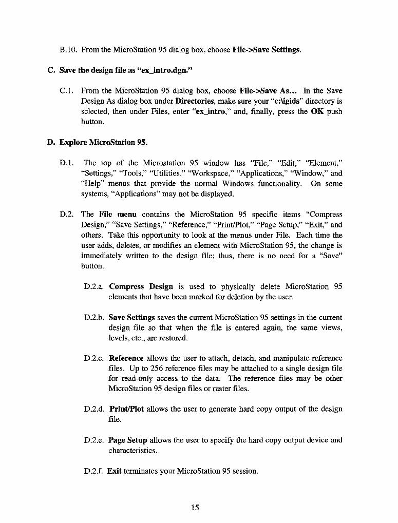
D.2. The File menu contains the MicroStation 95 specific items "Compress Design," "Save Settings," "Reference," "Print/Plot," "Page Setup," "Exit," and others. Take this opportunity to look at the menus under File. Each time the user adds, deletes, or modifies an element with MicroStation 95, the change is immediately written to the design file; thus, there is no need for a "Save" button.
D.2.a. Compress Design is used to physically delete MicroStation 95 elements that have been marked for deletion by the user.
D.2.b. Save Settings saves the current MicroStation 95 settings in the current design file so that when the file is entered again, the same views, levels, etc., are restored.
D.2.c. Reference allows the user to attach, detach, and manipulate reference files. Up to 256 reference files may be attached to a single design file for read-only access to the data. The reference files may be other MicroStation 95 design files or raster files.
D.2.d. Print/Plot allows the user to generate hard copy output of the design file.
D.2.e. Page Setup allows the user to specify the hard copy output device and characteristics.
D.2.f. Exit terminates your MicroStation 95 session.
15

D.3. The Edit menu contains the MicroStation 95 specific items "Undo," "Redo," and numerous others. Take this opportunity to look at the menus under Edit. Undo allows the user to undo the last MicroStation 95 command. Redo negates the last undo operation.
D.4. The Element menu contains the MicroStation 95 specific items "Attributes," "Cells," "Text," and several others. Take this opportunity to look at the menus under Element.
D.4.a. The Attributes menu allows the user to specify the Level or drawing plane (1-63) (individual levels may be viewed or hidden at any time), the Color (0-254), the Style (0-7 and Custom), the Weight or thickness (0-15), and the Class (Primary or Construction). Each MicroStation 95 element may have specific values of each of these attributes based upon the current settings when the element is added to the design file. There are tools to allow the user to change any of the attribute values.
D.4.b. The Cells menu allows the user to attach and detach cell libraries (a file containing a collection of cells) and to select a cell for placement from among the cells in a cell library. A cell is a collection of one or more MicroStation 95 elements that may be placed, manipulated, and deleted as one item. You may have only one cell library attached at any one time. Once a cell is placed, you no longer need the cell library attached.
D.4.c. The Text menu provides for the selection of font, height, width, line spacing, single-line justification, multiline justification, and other text attributes. Additionally, the Match push button allows the user to point at an existing text element in the design file and make the current settings equal to the selected element values.
D.5. The Settings menu contains the MicroStation 95 specific items "Design File ... ," "Level," "Snaps," "View Attributes," and several others. Take this opportunity to look at the menus under Settings.
D.5.a. The Design File menu allows the user to set or change many categories of items. We have used the Design File menu in section B above to set the Active Angle, Active Scale, Element Highlight Color, Coordinate Readout, and Working Units.
D.5.b. The Level Display menu allows the user to control which levels (1-63) are displayed and hidden for each view (1-8 views may be on at any
16

one time) and to control the active level (the level where all new user elements are placed). Level segregates the data allowing the user to view or not view the data on individual levels. View Levels can be applied to the single selected View Number (MicroStation 95 Window number) using "Apply" or to "All" views. The active level is indicated by a circle, the displayed level(s) are indicated by a black square, and hidden level(s) are indicated by gray squares. The active level applies to all views. IGIDS sets the active level to 2 and uses levels 3 through 62 for displaying graphics. IGIDS controls the level of each element placed by IGIDS. The user is prohibited from changing the active level by IGIDS. The user can use the IGIDS View command to control which of the levels 3 through 62 are displayed or hidden. Each IGIDS Alternative uses 4 levels with the first level being the centerline graphics, the second level being the lane graphics, the third level being the traffic control graphics, and the fourth level being the text. IGIDS displays an Alert dialog box upon startup to notify the user that "IGIDS will delete levels 3 through 62" giving the user the choice to continue ("OK") or stop ("Cancel").
D.5.c. The Snaps menu contains "Button Bar," "Nearest," "Keypoint," "Midpoint," "Center," "Origin," "Bisector," and "Intersection." The Button Bar creates a Snap Mode toolbox that can be moved around the window or docked along any edge. The Nearest Snap uses the closest points on elements. The Keypoint Snap uses predefined keypoints on elements. The Midpoint Snap uses the midpoints of elements and segments of elements. The Center Snap uses the centers and centroids of elements. The Origin Snap uses the origins of cells. The Bisector Snap uses the midpoints of entire elements. The Snap Modes constrain an element to: Intersection - intersect another element with the point of intersection at its starting or ending point; Tangent - be tangent to another element; Tangent From - be tangent to another element with the point of tangency at its starting or ending point; Perpendicular - be perpendicular to another element; Perp From -be perpendicular to another element with the point of intersection at its starting or ending point; Parallel - be parallel to another element; Through Point - pass through a particular point on the design plane; and Point On - start or end on another element.
D.5.d. The View Attributes menu allows the user to control whether Construction elements are displayed or hidden, whether Fill is active or inactive (shapes are filled), whether the Grid is displayed or hidden, whether Line Styles are displayed, whether Line Weights are displayed, whether Text is displayed, and other view attributed. View
17

Attributes can be applied to the single selected View Number (MicroStation 95 Window number) using "Apply" or to "All" views.
D.6. The Tools menu contains the MicroStation 95 specific items "Primary," "Standard," "Main," "3D" (if the design file is 3D), and numerous other tools. Take this opportunity to look at the menus under Tools.
D.6.a. In the Tools menu, if Primary does not have a check mark to its left then choose Primary. The Primary Tools menu will appear. Place the cursor on the top bar of the Primary Tools menu, press and hold the left button, drag the menu into the top of the MicroStation 95 window to the leftmost position under File, and, finally, release the left button. This action will dock the Primary Tools menu. The Primary Tools menu contains items for active color, level, style, and weight; element information; and AccuDraw.
D.6.a.l. Active Color specifies one of 255 colors (0-254) from an active Color Table. The value in the Color Table specifies a 24-bit, true-color value (16,777,216 color combinations) to be associated with the Active Color.
D.6.a.2. Active Level specifies one of 63 levels (1-63) or drawing planes. Level segregates the data allowing the user to view or not view the data. Individual levels may be viewed or hidden at any time.
D.6.a.3. Active Style specifies one of 8 predefined styles (0-7) or one of a virtually an unlimited number of Custom styles. Style defines the appearance of data (solid, dashed, dotted, etc.). The user may create his/her own Custom styles. IGIDS uses Custom styles for striping.
D.6.a.4. Active Weight specifies one of 16 predefmed weights (0-15). Weight defines the thickness or number of pixels displayed on the screen for graphics. When plotting the design file, the Weight can be converted to a line thickness.
D.6.b. In the Tools menu, if Standard does not have a check mark to its left then choose Standard. The Standard Tools menu will appear. Place the cursor on the top bar of the Standard Tools menu, press and hold the left button, drag the menu into the top of the MicroStation 95 window to the right of the Primary Tools menu and at the same horizontal position as the Primary Tools menu, and, finally, release the
18

left button. This action will dock the Standard Tools menu. The Standard Tools menu contains items New File, Open File, Save Design, Print, Cut, Copy, Paste, Undo, Redo, and Help.
D.6.c. When you started MicroStation 95, we had you choose Style>Command Window. The MicroStation 95 Command Window should be directly below the Primary Tools and Standard Tools menus. The fields within the MicroStation 95 Command Window include the following: left side top row is the Status Message field, left side middle row is the Command Message field, left side bottom row is the Key-in field, right side top row is the Inform Message field, right side middle row is the Prompt Message field, and right side bottom row is the Error/Warning Message field. In the Key-in field, you may enter up-arrow and down-arrow keys for command recall and selection and enter the home, end, delete, backspace, left-arrow, and right-arrow keys for command editing.
D.6.d. In the Tools menu, if Main->Main does not have a check mark to its left then choose Main. The Main Tools menu will appear. The Main Tools menu may be docked in a manner similar to that used for docking the Primary Tools and Standard Tools menus. The Main menu contains the MicroStation 95 commands to add, modify, and delete elements and are (from left to right and top to bottom): the Element Selection tool, Fence commands, Points commands, Linear Elements (Lines) commands, Patterns commands, Polygons (Shapes) commands, Arcs commands, Ellipses (Circle) commands, Tags commands, Text commands, Groups commands, Cells commands, Measure commands, Dimension commands, Change Attributes commands, Manipulate commands, Delete Element command, and Modify commands.
D.6.e. The 3D menu will be activated only if the design file is 3D. In the Tools->3D menu, if 3D View Control does not have a check mark to its left then choose 3D View Control. The 3D View Control menu will appear. The 3D View Control menu may be docked in a manner similar to docking the Primary Tools, Standard Tools, and Main menus. The 3D View Control menu contains (from left to right): Zoom In/Out, Change View Perspective, Set Display Depth, Set Active Depth, Show Display Depth, Show Active Depth, Change View Rotation, Camera Settings, and Render. To utilize the IGIDS Vertical Sight Distance command, you must be in a 3D design file and may need to set display depth to view the results. This will be covered in the training session on Vertical Sight Distance.
19

D.7. The Utilities menu contains the MicroStation 95 specific items "Key-in," "Install Fonts ... ," "MDL Applications," and several others. Take this opportunity to look at the menus under Utilities.
D.7.a. The Key-in dialog box allows the user to enter a MicroStation 95 command in the top field, to select a MicroStation 95 command from the hierarchical list of commands in the middle fields, or to select a MicroStation 95 command from the list of recent key-in commands in the bottom field. When you started MicroStation 95, we had you choose Style->Command Window. The left-side bottom row of the Command Window is the Key-in field and it provides the same functionality as the top field in the Key-in dialog box. In the top field in the Key-in dialog box, you may enter up-arrow and down-arrow keys for command recall and selection and enter the home, end, delete, backspace, left-arrow, and right-arrow keys for command editing.
D.7.b. The Install Fonts dialog box allows the user to install user-defined fonts. When IGIDS was installed on your computer, the instructions called for adding the IGIDS font to your font resource file. You may check this by selecting Utilities->Install Fonts... On the right side of the Font Installer dialog box, press the Open ... push button. In the Open Font Library dialog box under Directories:, select the device and directory for MicroStation 95 (normally "c:\win32app\microstation"), then select the directory for "wsmod\default\symb;" then, under Files:, choose font.rsc, and, finally, press the OK push button. On the right side of the Font Installer dialog box, examine the list for font number 59 named TrafficControL If the IGIDS TrafficControl font is not listed, please contact your system administrator to rectify the problem. Finally, press the Done push button.
D.7.c. The MDL Applications dialog box allows the user to load (start), unload (stop), and get additional information about MDL Applications. IGIDS is an MDL Application. Select Utilities->MDL Applications. In the MDL dialog box in the Available Applications group, select FONTEDIT from the list and then press the Load push button. In the Open Font Library dialog box under Directories:, select the device and directory for MicroStation 95 (normally "c:\win32app\microstation"), then select the directory for ''wsmod\default\symb; next, under Files:, choose font.rsc, and, finally, press the OK push button. In the Character Mapping dialog box in the Font group, choose 59 -TrafficControl and in the Display Mode group, choose the Label option Screen Font. Notice the traffic signal heads defmed under "3,"
20

"4," and "5"; a left-tum arrow defined under "1'' and "L;" a NEMA traffic signal controller defined under "n" and "N ;" a pretimed traffic signal controller defined under "p" and "P;" a right-tum arrow defmed under "r" and "R;" a stop sign defined under "s" and "S;" a through arrow defined under "t" and "T;" aU-tum arrow defined under ''u" and "U;" and a yield sign defined under "y" and "Y." Press the Done push button. Finally, press the "x" in the upper-right corner of the MDL dialog box.
D.8. The Workspace menu contains the MicroStation 95 specific items "Configuration ... ," "Button Assignments ... ," and several other items. Take this opportunity to look at the menus under Workspace.
D.S.a. The Configuration dialog box allows the user to specify many MicroStation 95 parameters. Select Workspace->Configuration, then under Category, select All (Alphabetical), and then under View/modify all configuration variables, select IGIDS_PATH. If IGIDS_PATH is not listed, please contact your system administrator to rectify the problem. IGIDS uses the value of IGIDS_PATH to locate where IGIDS is loaded on your computer. The normal value for IGIDS_PATH is "c:\igids" but IGIDS can be loaded in any device and directory.
D.S.b. The Button Assignments dialog box allows the user to specify the association between the buttons on the mouse and the meaning to MicroStation 95. Select Workspace->Button Assignments... The Data button specifies a coordinate to MicroStation 95 (or if the Tentative button was last used, it accepts the snapped, calculated coordinate) and is normally the left button on the mouse. The Tentative button specifies a coordinate to MicroStation 95 that causes MicroStation 95 to search the design file for an element close to the coordinate specified, calculate a coordinate based upon the current snap feature, move an enlarged cursor to the calculated coordinate, and highlight the selected element. If the snapped, calculated coordinate is not acceptable, the user may enter additional Tentative buttons until an acceptable coordinate is displayed. To accept the Tentative button snapped, calculated coordinate, the user would enter a single Data button (the location of the cursor for the Data button is not pertinent). The Tentative button is normally the center button on a three-button mouse, while the Tentative button is normally a left button/right button chord (left and right button pressed at the same time) on a two-button mouse. The Reset button specifies a reset or reject action to MicroStation 95 and is normally the right button on the mouse. The
21

definition of the Command button is not important because MicroStation 95 interprets any button on a dialog box to be a Command button. If the buttons are not assigned the way that you want them, select a button from the list and in the Button Definition Area, press the mouse button or combination of Alt keys and mouse buttons that you want. When completed, press the OK push button.
D.9. The Applications menu contains menus added by MicroStation 95 MDL applications and MBE applications. On some systems, "Applications" may not be displayed. Take this opportunity to look at the menus under Applications.
D.lO. The Window menu contains the MicroStation 95 specific items "Open/Close" and several others. Take this opportunity to look at the menus under Window. MicroStation 95 can have up to eight windows or views open simultaneously. Each window or view has its own size (height and width), location within the MicroStation 95 window, levels to display or hide (Settings->Levels>Display), view attributes (Settings->View Attributes), panning, zooming, rotation, and orientation (for 3D files: top, bottom, left, orthogonal, etc.). Choose Window->Open/Close; if 1 (for window/view 1) does not have a check mark to its left then select 1 (window/view 1 will be opened) and if any of 2 through 8 has a check mark to its left then select each one (the window/view will be closed).
D.11. The Help menu contains the MicroStation 95 specific items to assist the user in using and finding online information about MicroStation 95. Take this opportunity to look at the menus under Help. The Key-in Browser opens the MicroStation 95 Key-in dialog box discussed in section D.7.a.
D.12. Each MicroStation 95 window or view has a bar across the top border, a slider along the right border, and a bar and slider along the bottom border. Take this opportunity to look at the borders for Window 1.
D.12.a. The bar across the top border of a MicroStation 95 window or view contains the window name on the left and three icons on the right. The three icons are, from left to right, the Collapse icon, the Size icon (a one-window icon means the MicroStation 95 window or view will be enlarged to fit the MicroStation 95 window, whereas a two-window icon means the MicroStation 95 window or view will be reduced to its previous size), and the Close icon. When the MicroStation 95 window or view is displaying the one-window Size icon, the MicroStation 95 window or view may be moved or resized. Pressing and holding the left mouse button on the top bar and then moving the mouse will cause the window or view to be moved within the MicroStation 95 window.
22

Pressing and holding the left mouse button on any of the four corners of the MicroStation 95 window or view will resize both the horizontal and vertical dimensions of the MicroStation 95 window or view. Pressing and holding the left mouse button on any of the four edges of the MicroStation 95 window or view will resize either the horizontal and vertical dimensions of the MicroStation 95 window or view.
D.12.b. The slider along the right border of a MicroStation 95 window or view allows the user to pan the design file in the vertical direction using either the up arrow, slider button, or the down arrow.
D.12.c. The bar and slider along the bottom border contains, from left to right, the Update View icon (a paint brush) (paint or redraw), the Zoom In icon (a "+" sign) (increase magnification), the Zoom Out icon (a "-" sign) (decrease magnification), the Window Area icon (zoom in by rectangle), the Fit View icon (view all elements), the Rotate View icon, the Pan View icon, the View Previous icon, the View Next icon, the left arrow, the slider button, and the right arrow. The bar along the bottom edge of a MicroStation 95 window or view applies only to the single MicroStation 95 window or view.
E. Use MicroStation 95 to Draw a Leg Centerline.
E.l. Set the element attributes.
E.l.a. Select the Active Color icon (leftmost icon) from the MicroStation 95 Primary Tools menu at the top and choose the yellow color (color = 4). The Active Color icon should now be colored yellow.
E.l.b. Select the Active Level icon (next icon to the right) from the MicroStation 95 Primary Tools menu at the top and choose level 2 (level = 2). The Active Level icon should now have 2 displayed on its left side.
E.l.c. Select the Active Style icon (next icon to the right) from the MicroStation 95 Primary Tools menu at the top and choose dash-dot style (style= 4). The Active Style icon should now display a dash-dot line on the left and a 4 on the right.
E.l.d. Select the Active Weight icon (next icon to the right) from the MicroStation 95 Primary Tools menu at the top and choose weight 0 (weight= 0). The Active Weight icon should now have a thin line on the left and a 0 on the right.
23

E.2. Place leg centerline.
E.2.a. Place a 150-meter line at 45 degrees. From the MicroStation 95 Main Tool menu, select the Linear Elements palette (row 2, right icon) and drag it into the MicroStation 95 window. From the Linear Elements palette, choose the Place Line icon (2nd from left on the top row). From the Place Line dialog box, select Length to be active (an "X" will appear), enter a value of 150 meters (enter the tab character to set the number), select Angle to be active (an "X" will appear), and enter a value of 45 degrees (enter the tab character to set the number). In the MicroStation 95 Command Window Key-in field, enter "xy=5010,5010" plus a carriage return. This entry tells MicroStation 95 that the line should start at an x-coordinate of 5010 meters and a ycoordinate of 5010 meters. In Window 1, press the Fit View icon (the fifth icon from the left); the line should be visible.
E.2.b. Place a 150-meter line at 30 degrees. In the MicroStation 95 window, choose Settings->Snaps. If Keypoint does not have a check mark to its left, then select Keypoint. In the Inform Message field, "TP=KeyPT" should be displayed. From the Place Line dialog box, select Length to be active, enter a value of 150 meters, select Angle to be active, and enter a value of 30 degrees. Move the cursor in Window 1 near the top-right end of the previously placed line and press the Tentative button. In the Status Message field, "5116.0660, 5116.0660" should be displayed, a larger cursor should be positioned on the top-right end of the previously placed line, and the previously placed line should be highlighted. Now press the Data button to accept this tentative point. In Window 1, press the Fit View icon; both lines should be visible. Close the Linear Elements palette by selecting the "X" in the upper-right corner.
E.2.c. Place a 500-meter radius iillet with truncate between the two lines. From the MicroStation 95 Main Tool menu, select the Modify palette (bottom row right icon) and drag it into the MicroStation 95 window. From the Modify palette, choose the Construct Circular Fillet icon (next to the last icon). From the Construct Circular Fillet dialog box, enter a Radius of 500 meters and set the Truncate option to Both. Move the cursor over the 1st line and press the Data button (MicroStation 95 will highlight the first line); then move the cursor over the 2nd line and press the Data button (MicroStation 95 will highlight the second line and construct and highlight a 500-meter circular fillet); and, finally, press the Data button anywhere to accept
24

the fillet. In Window 1, press the Update View icon; both lines and the arc of a circle should be visible. Close the Modify palette by selecting the "X" in the upper-right corner.
F. Save the MicroStation 95 design file settings.
F.l. Choose MicroStation 95 File->Save Settings.
G. Plot the drawing.
G.l. Choose MicroStation 95 File->Print/Plot. From the Plot dialog box, choose File->Preview. From the Plot Preview dialog box, choose Setup->Page. In the Print Setup dialog box, in the Printer group choose a Name, in the Orientation group choose Landscape, and press the OK push button. From the Plot Preview dialog box, choose File->Plot. Get your plot from the printer and check your plot. Close the Plot dialog box by selecting the "X" in the upper-right corner.
25
/
/ /
/
/
/
/
/
/
/
H. Exit MicroStation 95.
/
/
/
/
/
/ /
/
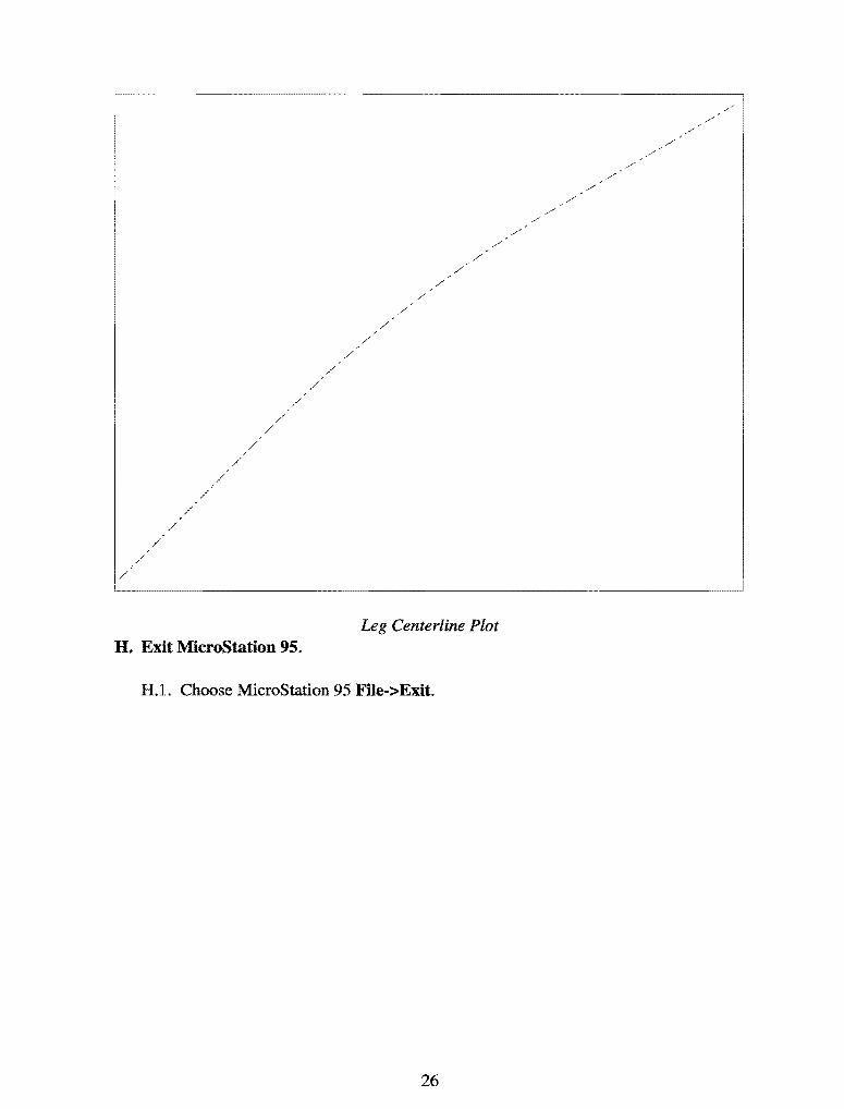
Leg Centerline Plot
H.l. Choose MicroStation 95 File->Exit.
26
/ /

SIMPLE EXAMPLE
Objective: Create the graphics for a simple example.
Activity: Become comfortable with IGIDS by stepping through a simple example that describes how to load a standard 4x4 intersection.
Background: Intersection analysis begins by defining the geometry of the intersection. Several common intersections are available for loading as a beginning step in the analysis process.
A. Start MicroStation 95 and create a 2D design file "ex_ 4x4.dgn" using the seed file ''train2d.dgn."
A.l. From the Windows NT Start Menu in the lower left comer of the screen, choose Start->Programs->MicroStation95->MicroStation95.
A.2. From the MicroStation 95 Manager dialog box, choose Style->Command Window.
A.3. From the MicroStation 95 Manager dialog box, choose File->New.
A.4. From the Create Design File dialog box, choose Select within the Seed File group.
A.5. From the Select Seed File dialog box under Directories, make sure your "c:\igids" directory is selected; then, under Files, choose "train2d.dgn," and, finally, press the OK push button.
A.6. From the Create Design File dialog box under Directories, make sure your "c:\igids" directory is selected; then, under Files, enter "ex_ 4x4." Finally, press the OK push button.
A.7. From the MicroStation 95 Manager dialog box under Directories, make sure your "c:\igids" directory is selected; then, under Files, select "ex_ 4x4.dgn," and next press the OK push button.
A.8. If a MicroStation 95 Restricted Use dialog box appears for Academic Edition, drag the MicroStation 95 Restricted Use dialog box off the screen.
B. Start IGIDS
B.l. In the MicroStation 95 Command Window Key-in field, enter "mdl load igids" plus a carriage return. IGIDS displays an Alert dialog box to notify the user that "IGIDS will delete levels 3 through 62," giving the user the
27

choice to continue ("OK") or stop ("Cancel"). To continue, press the OK push button when the Alert dialog box appears. When ready, IGIDS will report "IGIDS V<vn>-S<sn>: Ready (<units> Units)" in the MicroStation 95 Command Window Command Message field where <vn> is the IGIDS Version Major and Minor Number, where <sn> is the IGIDS Structure Number, and <units> is either "English" or "Metric." The structure number and <units> of a saved IGIDS database must match the structure number of IGIDS being executed and the current <units> of the design file to be loaded by IGIDS.
B.2. An IGIDS Side Bar Menu will appear. Drag the IGIDS Side Bar Menu to the upper-left comer of the MicroStation window, close all other MicroStation 95 windows except Window 1, and resize Window 1 to not overlap the IGIDS Side Bar Menu.
C. Place an intersection that is typical of those found in many areas.
C.l. From the IGIDS Side Bar Menu, select LOADFROM->STANDARD->4x4.
C.2. When "DataPt/Reset: Alternative center/end command" is shown in the MicroStation 95 Command Window Prompt Message field, enter "xy=5000,5000" plus a carriage return in the MicroStation 95 Command Window Key-in field. This entry tells MicroStation 95 that the intersection should be centered at an x-coordinate of 5000 meters and y-coordinate of 5000 meters.
C.3. When "Key-in: Alternative number [1]" appears in the MicroStation 95 Command Window Prompt Message field, enter a carriage return or the enter key in the MicroStation 95 Command Window Key-in field. This selects the default alternative number (1). IGIDS will then draw the graphics that represent this alternative. In Window 1, press the Fit View icon (the fifth icon from the left). The intersection should be visible.
D. Save the MicroStation 95 design ille settings.
D.l. Choose MicroStation 95 File->Save Settings.
E. Plot the drawing.
E.1. Choose MicroStation 95 File->Print/Plot. From the Plot dialog box, choose File->Preview. From the Plot Preview dialog box, choose Setup->Page. In the Print Setup dialog box, in the Printer group choose a Name, in the Orientation group choose Landscape, and press the OK push button. From the Plot Preview dialog box, choose File->Plot. Get your plot from the printer and check your plot. Close the Plot dialog box by selecting the "X" in the upper-right comer.
28

4X4
Standard 4X4
I
I I I ,I I
II II
I I I I I I
I I I I
Simple Example Plot
F. Save the intersection to a database tile for later use.
F.l. From the IGIDS Side Bar Menu, select SAVE TO-> Data Base.
F.2. In the IGIDS Database File dialog box under Directories, make sure your "c:\igids" directory is selected; then, under Files, enter "ex_ 4x4." Finally, press the OK push button. IGIDS will save the intersection data to the file "ex_ 4x4.dbs."
G. Exit IGIDS.
G.l. From the IGIDS Side Bar Menu, select END IGIDS.
H. Exit MicroStation 95.
H.l. Choose MicroStation 95 File->Exit.
29

30

VEHICLE TURN TEMPLATES
Objective: Design the curb lane curb return.
Activity: Generate and manipulate a vehicle tum template for a WB-60-18 truck and modify the curb return radius.
Background: To determine the curb return radius between adjacent legs of an intersection, one or more vehicle tum templates should be generated and manipulated. The vehicle tum template tracks the outside front bumper and inside real axle positions of the selected standard AASHTO vehicle as the front axle follows a circular arc of a circle for the specified radius and, in addition, provides an optional safety zone. The curb return radius should be modified to accommodate the critical path.
A. Start MicroStation 95 and create a 2D design me "ex_txtom.dgn" using the seed me ''train2d.dgn."
A.l. From the Windows NT Start Menu in the lower-left comer of the screen, choose Start->Programs->MicroStation95->MicroStation95.
A.2. From the MicroStation 95 Manager dialog box, choose Style->Command Window.
A.3. From the MicroStation 95 Manager dialog box, choose File->New.
A.4. From the Create Design File dialog box, choose Select within the Seed File group.
A.5. From the Select Seed File dialog box under Directories, make sure your "c:\igids" directory is selected; then, under Files, choose "train2d.dgn," and, finally, press the OK push button.
A.6. From the Create Design File dialog box under Directories, make sure your "c:\igids" directory is selected; then, under Files, enter "ex_txtom," and, finally, press the OK push button.
A.7. From the MicroStation 95 Manager dialog box under Directories, make sure your "c:\igids" directory is selected; then, under Files, select "ex_txtom.dgn," and, finally, press the OK push button.
A.8. If a MicroStation 95 Restricted Use dialog box appears for Academic Edition, drag the MicroStation 95 Restricted Use dialog box off the screen.
31

B. Start IGIDS.
B.l. In the MicroStation 95 Command Window Key-in field, enter "mdl load igids." Press the OK push button when the IGIDS Alert dialog box appears.
B.2. Drag the IGIDS Side Bar Menu to the upper-left corner of the MicroStation window.
C. Load the saved IGIDS database ex_ 4x4.dbs.
C.l. From the IGIDS Side Bar Menu, select LOADFROM->DATABASE.
C.2. In the Intersection database filename dialog box under Directories, make sure your "c:\igids" directory is selected; then, under Files, choose "ex_ 4x4.dbs," and, finally, press the OK push button. IGIDS will then draw the graphics that represent this saved IGIDS database. In Window 1, press the Fit View icon. The intersection should be visible.
D. Adjust the angle of one leg by 3.25 degrees.
D.l. From the IGIDS Side Bar Menu, select ROTATE->LEG.
D.2. When "Key-in: Rotation angle [1.0]" appears in the MicroStation 95 Command Window Prompt Message field, enter "3.25" plus a carriage return key in the MicroStation 95 Command Window Key-in field.
D.3. IGIDS will highlight the leg nearest the top of the screen and issue the prompt "DataPt/Reset: accept & define dir. & rotate/reidentify" in the MicroStation 95 Command Window Prompt Message field. Click the right mouse button to signal a Reset and the leg nearest the top of the screen will return to its normal color.
D.4. In response to the prompt "DataPt: identify a Leg" in the MicroStation 95 Command Window Prompt Message field, place a Data point on the leg nearest the bottom of the screen.
D.5. When "DataPt/Reset: accept & define dir. & rotate/reidentify" appears in the MicroStation 95 Command Window Prompt Message field, place a Data point to the right of the highlighted leg in a location such that the perpendicular projection of the point falls on the highlighted centerline of the leg. IGIDS will rotate the leg 3.25 degrees counterclockwise and report statistics in the MicroStation 95 Command Window Inform Message field.
D.6. In Window 1, press the Zoom In icon (the second icon from the left). Repeat this procedure four times: move the cursor in Window 1 so that the
32

upper-left comer of the zoom-in rectangle is just to the upper left of the center of the intersection and press the Data button.
E. Place the vehicle turn template for a WB-60-18 truck.
E.l. From the IGIDS Side Bar Menu, select TOOLS->TurnTemplate->WB-60-18.
E.2. In response to the prompt "DataPt: identify inbound leg" in the MicroStation 95 Command Window Prompt Message field, place a Data point on the leg nearest the bottom of the screen.
E.3. When "DataPtJReset: accept/reidentify" appears in the MicroStation 95 Command Window Prompt Message field, place a Data point anywhere in the window to accept the leg.
E.4. In response to the prompt "DataPtJReset: identify outbound leg/reidentify inbound leg" in the MicroStation 95 Command Window Prompt Message field, place a Data point on the leg nearest the right of the screen.
E.5. When "DataPtJReset: accept/reidentify" appears in the MicroStation 95 Command Window Prompt Message field, place a Data point anywhere in the window to accept the leg.
E.6. In response to the prompt "Key-in/Reset: tum radius [14.0]/reidentify outbound leg" in the MicroStation 95 Command Window Prompt Message field, enter a carriage return or the enter key in the MicroStation 95 Command Window Key-in field.
E.7. When "Key-in/Reset: clearance (O=none)[0.2]/ reid outbound leg" appears in the MicroStation 95 Command Window Prompt Message field, enter a carriage return or the enter key in the MicroStation 95 Command Window Key-in field. IGIDS will generate a vehicle tum template for a WB-60-18 truck with a tum radius of 14 meters (15.4 yards), with a 0.2-meter (0.18-yard) clearance zone, and with a tum angle of 93.25 degrees; rotate the vehicle tum template to the angle for the inbound leg; place the outside front axle of the vehicle tum template at the stop line of the curb lane; this will allow you to dynamically move the vehicle tum template. Position the vehicle turn template so that the beginning of the yellow clearance line on the left of the vehicle tum template is touching the inner edge of the curb lane on the bottom leg, and the highest point of the yellow clearance line is touching the inner edge of the curb lane on the right leg. Press the data button to set the position. You may continue to move the vehicle tum template by pressing the data button. MicroStation 95 windowing commands may be executed while you are moving the vehicle tum template. Press the Reset button when you are finished.
33

F. Modify the curb return radius for the leg.
F.l. From the IGIDS Side Bar Menu, select ADD->CURB CR·>BY KEY-IN. IGIDS will highlight the last identified leg, the leg on the right.
F.2. In response to the prompt "DataPt/Reset: accept/reidentify" in the MicroStation 95 Command Window Prompt Message field, press the Reset button.
F.3. When "DataPt/Reset: identify Leg for adding Curb Return" appears in the MicroStation 95 Command Window Prompt Message field, place a Data point on the leg nearest the bottom of the screen.
F.4. In response to the prompt "DataPt/Reset: accept/reidentify" in the MicroStation 95 Command Window Prompt Message field, place a Data point anywhere in the window to accept the leg.
F.5. When "Key-in/Reset: curb return radius (min=O.lO M)/reidentify leg" appears in the MicroStation 95 Command Window Prompt Message field, key in various values of the curb return radius until the bottom yellow clearance line is touching or is above the green curb return. A value of 22 meters (20 yards) may be acceptable.
G. Save the MicroStation 95 design file settings.
G.l. Choose MicroStation 95 File->Save Settings.
H. Plot the drawing.
H.l. Choose MicroStation 95 File->Print/Plot. From the Plot dialog box, choose File->Preview. From the Plot Preview dialog box, choose Setup->Page. In the Print Setup dialog box, in the Printer group choose a Name, in the Orientation group choose Landscape, and press the OK push button. From the Plot Preview dialog box, choose File->Plot. Get your plot from the printer and check your plot. Close the Plot dialog box by selecting the "X" in the upper-right comer.
34

Vehicle Tum Template Plot
I. Save the intersection to a database file for later use.
I.l. From the IGIDS Side Bar Menu, select SAVE TO->Data Base.
1.2. In the IGIDS Database File dialog box under Directories, make sure your "c:\igids" directory is selected, then, under Files, enter "ex_txtom," and, finally, press the OK push button. IGIDS will save the intersection data to the file "ex_txtom.dbs."
J. Exit IGIDS.
J.l. From the IGIDS Side Bar Menu, select END IGIDS.
K. Exit MicroStation 95.
K.l. Choose MicroStation 95 File->Exit.
35

36

HORIZONTAL SIGHT DISTANCE
Objective: Evaluate the horizontal sight distance for yield sign control, no control, and stop sign control.
Activity: Place the horizontal sight distance triangle for yield sign control, no control, and stop sign controL
Background: A Policy on Geometric Design of Highways and Streets 1994 by the American Association of State Highway and Transportation Officials defines procedures to calculate the required horizontal sight distance between adjacent legs of an intersection for yield sign control, no control, and stop sign control. The area within this horizontal sight distance triangle must be clear of major sight obstructions to ensure safe operation of the intersection.
A. Start MicroStation 95 and create a 2D design file "ex_hsd.dgn" using the seed ille "train2d.dgn."
A.l. From the Windows NT Start Menu in the lower-left corner of the screen, choose Start->Programs->MicroStation95->MicroStation95.
A.2. From the MicroStation 95 Manager dialog box, choose Style->Command Window.
A.3. From the MicroStation 95 Manager dialog box, choose File-> New.
A.4. From the Create Design File dialog box, choose Select within the Seed File group.
A.5. From the Select Seed File dialog box under Directories, make sure your "c:\igids" directory is selected; then, under Files, choose "train2d.dgn," and, finally, press the OK push button.
A.6. From the Create Design File dialog box under Directories, make sure your "c:\igids" directory is selected; then, under Files, enter "ex_hsd," and, finally, press the OK push button.
A. 7. From the MicroStation 95 Manager dialog box under Directories, make sure your "c:\igids" directory is selected; then, under Files, select "ex_hsd.dgn," and, finally, press the OK push button.
A.8. If a MicroStation 95 Restricted Use dialog box appears for Academic Edition, drag the MicroStation 95 Restricted Use dialog box off the screen.
37

B. Start IGIDS.
B.l. In the MicroStation 95 Command Window Key-in field, enter "mdl load igids." Press the OK push button when the IGIDS Alert dialog box appears.
B.2. Drag the IGIDS Side Bar Menu to the upper-left corner of the MicroStation window.
C. Load the saved IGIDS database ex_ 4x4.dbs.
C.l. From the IGIDS Side Bar Menu, selectLOADFROM->DATABASE.
C.2. In the Intersection database filename dialog box under Directories, make sure your "c:\igids" directory is selected; then, under Files, choose "ex_4x4.dbs," and, finally, press the OK push button. In Window 1, press the Fit View icon. In Window 1, press the Zoom In icon. Repeat this procedure two times: move the cursor in Window 1 so that the upper left corner of the zoom in rectangle is just to the upper left of the center of the intersection and press the Data button. In the Zoom-In dialog box, change 2.0 to 1.5, move the cursor in Window 1 so that the upper left corner of the zoom-in rectangle is just to the upper left of the center of the intersection, press the Data button, and in the Zoom-In dialog box, change 1.5 back to 2.0.
D. Place the horizontal sight distance triangle for yield sign control.
D.1. From the IGIDS Side Bar Menu, select TOOLS->Sight Dist->HorizontalYield.
D.2. In response to the prompt "DataPt: identify yielding Inbound Lane" in the MicroStation 95 Command Window Prompt Message field, place a Data point on the stop line of the median lane of the leg nearest the bottom of the screen.
D.3. When "DataPt/Reset: accept/reidentify" appears in the MicroStation 95 Command Window Prompt Message field, place a Data point anywhere in the window to accept the lane.
D.4. In response to the prompt "Key-in/Reset: yielding Leg speed [48 km/h ]/reidentify" in the MicroStation 95 Command Window Prompt Message field, enter a carriage return or the enter key in the MicroStation 95 Command Window Key-in field.
38

D.5. When "DataPt/Reset: identify conflicting Leg/reidentify inbound lane" appears in the MicroStation 95 Command Window Prompt Message field, place a Data point on the leg nearest the right of the screen.
D.6. In response to the prompt "DataPt/Reset: accept/reidentify" in the MicroStation 95 Command Window Prompt Message field, place a Data point anywhere in the window to accept the leg.
D.7. When "Key-in/Reset: conflicting Leg speed [48 kmlh]/reidentify" appears in the MicroStation 95 Command Window Prompt Message field, enter a carriage return or the enter key in the MicroStation 95 Command Window Key-in field. IGIDS will calculate and display the horizontal sight distance triangle for a passenger car. Starting at the car on the inbound lane, the path that the car would take from its position on the inbound lane to the conflict point within the intersection is drawn. Then, the path that the car on the conflicting leg would take from its position on the conflicting leg to the conflict point within the intersection is drawn. Finally, a line is drawn from the driver's eye position within the car on the inbound lane to the front bumper position of the car on the conflicting leg. The distance from the conflict point within the intersection to the front bumper position of the car on the inbound lane and to the car on the conflicting leg is calculated based upon the speeds specified and procedures in A Policy on Geometric Design of Highways and Streets 1990 and A Policy on Geometric Design of Highways and Streets 1994, American Association of State Highway and Transportation (AASHTO).
E. Place the horizontal sight distance triangle for no control.
E.l. From the IGIDS Side Bar Menu, select TOOLS->Sight Dist->Horizontal-> No Control.
E.2. In response to the prompt "DataPt: identify first Inbound Lane" in the MicroStation 95 Command Window Prompt Message field, place a Data point on the stop line of the median lane of the leg nearest the bottom of the screen.
E.3. When "DataPt/Reset: accept/reidentify" appears in the MicroStation 95 Command Window Prompt Message field, place a Data point anywhere in the window to accept the lane.
E.4. In response to the prompt "Key-in/Reset: first Leg speed [48 kmlh ]/reidentify" in the MicroStation 95 Command Window Prompt Message field, enter a carriage return or the enter key in the MicroStation 95 Command Window Key-in field.
39

E.5. When "DataPt/Reset: identify second Inbound Lane/reidentify inbound leg" appears in the MicroStation 95 Command Window Prompt Message field, place a Data point on the stop line of the median lane of the leg nearest the right of the screen.
E.6. In response to the prompt "DataPt/Reset: accept/reidentify" in the MicroStation 95 Command Window Prompt Message field, place a Data point anywhere in the window to accept the lane.
E.7. When "Key-in/Reset: second Leg speed [48 kmlh]/reidentify" appears in the MicroStation 95 Command Window Prompt Message field, enter a carriage return or the enter key in the MicroStation 95 Command Window Key-in field. IGIDS will calculate and display the horizontal sight distance triangle for a passenger car. Starting at the car on the first inbound lane, the path that the car would take from its position on the first inbound lane to the conflict point within the intersection is drawn. Then the path that the car on the second inbound lane would take from its position on the second inbound lane to the conflict point within the intersection is drawn. Finally, a line is drawn from the driver's eye position within the car on the first inbound lane to the driver's eye position within the car on the second inbound lane. The distance from the conflict point within the intersection to the front bumper position of the car on the first inbound lane and to the front bumper position of the car on the second inbound lane is calculated based upon the speeds specified and procedures in A Policy on Geometric Design of Highways and Streets 1990 and A Policy on Geometric Design of Highways and Streets 1994, American Association of State Highway and Transportation (AASHTO).
F. Place the horizontal sight distance triangle for stop sign control.
F. I. From the IGIDS Side Bar Menu, select TOOLS->Sight Dist->Horizontal-> Stopped.
F.2. In response to the prompt "DataPt: identify stopped Inbound Lane" in the MicroStation 95 Command Window Prompt Message field, place a Data point on the stop line of the median lane of the leg nearest the bottom of the screen.
F.3. When "DataPt/Reset: accept/reidentify" appears in the MicroStation 95 Command Window Prompt Message field, place a Data point anywhere in the window to accept the lane.
FA. In response to the prompt "DataPt/Reset: identify conflicting Leg/reidentify inbound lane" appears in the MicroStation 95 Command Window Prompt Message field, place a Data point on the leg nearest the right of the screen.
40

F.6. When "DataPt/Reset: accept/reidentify" appears in the MicroStation 95 Command Window Prompt Message field, place a Data point anywhere in the window to accept the leg.
F.7. In response to the prompt "Key-in/Reset: conflicting Leg speed [48 kmlh]/reidentify" in the MicroStation 95 Command Window Prompt Message field, enter a carriage return or the enter key in the MicroStation 95 Command Window Key-in field.
F.8. When "Key-in, DataPt/Reset: stopped bumper pos.[O M]/reidentify" appears in the MicroStation 95 Command Window Prompt Message field, enter a carriage return or the enter key in the MicroStation 95 Command Window Key-in field. IGIDS will calculate and display the horizontal sight distance triangle for a passenger car with its front bumper at the stop line. Starting at the car on the inbound lane, the path that the car would take from its position on the inbound lane to the conflict point within the intersection is drawn. Then, the path that the car on the conflicting leg would take from its position on the conflicting leg to the conflict point within the intersection is drawn. Finally, a line is drawn from the driver's eye position within the car on the inbound lane to the front bumper position of the car on the conflicting leg. The distance from the conflict point within the intersection to the front bumper position of the car on the inbound lane and to the front bumper position of the car on the conflicting leg is calculated based upon the speed specified and procedures in A Policy on Geometric Design of Highways and Streets 1990 and A Policy on Geometric Design of Highways and Streets 1994, American Association of State Highway and Transportation (AASHTO).
G. Save the MicroStation 95 design file settings.
G .1. Choose MicroStation 95 File->Save Settings.
H. Plot the drawing.
H.l. Choose MicroStation 95 File->PrintJPlot. From the Plot dialog box, choose File->Preview. From the Plot Preview dialog box, choose Setup->Page. In the Print Setup dialog box, in the Printer group choose a Name, in the Orientation group choose Landscape, and press the OK push button. From the Plot Preview dialog box, choose File->Plot. Get your plot from the printer and check your plot. Close the Plot dialog box by selecting the "X" in the upper-right comer.
41

Horizontal Sight Distance Plot
I. Save the intersection to a database tlle for later use.
I.l. From the IGIDS Side Bar Menu, select SAVE TO->Data Base.
I.2. In the IGIDS Database File dialog box under Directories, make sure your "c:\igids" directory is selected; then, under Files, enter "ex_hsd," and, finally, press the OK push button. IGIDS will save the intersection data to the file "ex_hsd.dbs."
J. Exit IGIDS.
J.l. From the IGIDS Side Bar Menu, select END IGIDS.
K. Exit MicroStation 95.
K.l. Choose MicroStation 95 File->Exit.
42
VERTICAL SIGHT DISTANCE
Objective: Evaluate the vertical sight distance for yield sign controL
Activity: Place the horizontal sight distance triangle for yield sign control and check for obstructions within the horizontal sight distance triangle.
Background: A Policy on Geometric Design of Highways and Streets 1994 by the American Association of State Highway and Transportation Officials defines procedures to calculate the required horizontal sight distance between adjacent legs of an intersection for yield sign control, no control, and stop sign controL The area within this horizontal sight distance triangle must be clear of major sight obstructions to ensure safe operation of the intersection. To aid in the identification of any major sight obstruction within this horizontal sight distance triangle, the triangle file from a Digital Terrain Model containing the terrain and man-made features that may obstruct sight may be attached as a reference file and IGIDS will determine whether individual sight lines are obstructed. Several viewing options are provided.
A. Start MicroStation 95 and create a 3D design file ''train3d.dgn" using the seed file "seed3d.dgn."
A.l. From the Windows NT Start Menu in the lower-left comer of the screen, choose Start->Programs->MicroStation95->MicroStation95.
A.2. From the MicroStation 95 Manager dialog box, choose Style->Command Window.
A.3. From the MicroStation 95 Manager dialog box, choose File-> New.
A.4. From the Create Design File dialog box, choose Select within the Seed File group.
A.5. From the Select Seed File dialog box under Directories, select the device and directory for MicroStation 95 (normally "c:\win32app\microstation"); then select the directory for "wsmod\default\seed;" then, under Files, select "seed3d.dgn." Finally, press the OK push button.
A.6. From the Create Design File dialog box under Directories, make sure your "c:\igids" directory is selected; then under Files, enter "train3d," and, finally, press the OK push button.
A. 7. From the MicroStation 95 Manager dialog box under Directories, make sure your "c:\igids" directory is selected; then, under Files, select "train3d.dgn," and, finally, press the OK push button.
43

A.8. If a MicroStation 95 Restricted Use dialog box appears for Academic Edition, drag the MicroStation 95 Restricted Use dialog box off the screen.
B. Set the MicroStation 95 Design File Settings.
B.l. From the MicroStation 95 dialog box, choose Settings->Design File ••.
B.2. In the Design File Settings dialog box under Category, choose Active Angle. In the Modify Active Angle Parameters area, in the Active Angle box, enter "0.0."
B.3. In the Design File Settings dialog box under Category, choose Active Scale. In the Modify Active Scale area, press the "1.0" button and ensure that the lock to the right of the X Scale and Y Scale boxes is in the locked position (press the lock if it is not in the locked position).
B.4. In the Design File Settings dialog box under Category, choose Color. In the Modify Color Settings area, press the Element Highlight Color button and choose the color magenta.
B.5. In the Design File Settings dialog box under Category, choose Coordinate Readout. In the Modify Coordinate Readout Parameters area, in the Coordinates group, for Format select Working Units and for Accuracy select an appropriate number of decimals.
B.6. In the Design File Settings dialog box under Category, choose Working Units. In the Modify Working Unit Parameters area, in the Units Name group, in the Master Units box, enter "ft" or "FT" for English units or enter "m" or "M" for metric units and in the Sub Units box, enter an appropriate designation for subunits. In the Resolution group, in the <master units> Per <sub units> box, enter the number of subunits per master unit and in the Pos Units Per <sub units> box, enter an appropriate number. Please check with your Graphics Coordinator for appropriate values for these settings. This IGIDS Training Course is based on metric units so enter ''m" in the Master Units box and enter "mm" in the Sub Units box. Also enter 1000 in the mm Perm box and enter 100 in the Pos Units Per mm box.
B.7. In the Design File Settings dialog box, press the OK push button. An Alter dialog box may appear warning you that "Changing your Working Units will change the size of existing elements;" press the OK push button.
B.8. From the MicroStation 95 dialog box, choose Settings-> View Attributes.
B.9. In the View Attributes dialog box, set Dynamics on, Fast Cells off, Fast Curves off, Fast Font off, Fill on, Level Symbology otT, Line Styles on,
44

Line Weights on, Text on, press the All button, and close the View Attributes dialog box.
B.lO. From the MicroStation 95 Main menu, choose the Delete Element icon (bottom left icon) then place a Data point on the cube in Window 2 -Isometric View, and finally place a Data point anywhere in the window to accept the element for deletion.
B.ll. Close Window 2 Isometric View, Window 3- Front View, and Window 4 - Right View by selecting the "X" in the upper right corner in each window.
B.l2. In Window 1- Top View, move the cursor to the bottom-right corner of the window until the double-headed, 45 degree angle arrow appears. Then press and hold the cursor, drag the cursor to the bottom-right corner of the MicroStation 95 window, and finally release the cursor button.
B.13. From the MicroStation 95 dialog box, choose File->Compress Design.
B.14. From the MicroStation 95 dialog box, choose File->Save Settings.
C. Save the design file as "ex_ vsd.dgn."
C.l. From the MicroStation 95 dialog box, choose File->Save As ••• In the Save Design As dialog box under Directories, make sure your "c:\igids" directory is selected; then, under Files, enter "ex_vsd," and, finally, press the OK push button.
D. Start IGIDS.
D.l. In the MicroStation 95 Command Window Key-in field, enter "mdl load igids." Press the OK push button when the IGIDS Alert dialog box appears.
D.2. Drag the IGIDS Side Bar Menu to the upper-left corner of the MicroStation window and adjust Window 1 Top View to accommodate the IGIDS Side Bar Menu.
E. Place an intersection that is typical of those found in many areas.
E. I. From the IGIDS Side Bar Menu, select LOADFROM->STANDARD->4x4.
E.2. When ''DataPt/Reset: Alternative center/end command" is shown in the MicroStation 95 Command Window Prompt Message field, enter ''xy=SOOO,SOOO" plus a carriage return in the MicroStation 95 Command Window Key-in field.
45

E.3. When "Key-in: Alternative number [1)" appears in the MicroStation 95 Command Window Prompt Message field, enter a carriage return or the enter key in the MicroStation 95 Command Window Key-in field. In Window 1 - Top View, press the Fit View icon. In Window 1 Top View, press the Zoom-In icon. Repeat this procedure two times: move the cursor in Window 1 Top View so that the upper-left corner of the zoom-in rectangle is just to the upper left of the center of the intersection and press the Data button. In the Zoom In dialog box, change 2.0 to 1.6, move the cursor in Window 1 - Top View so that the upper-left corner of the zoom in rectangle is just to the upper left of the center of the intersection, press the Data button, and in the Zoom In dialog box, change 1.6 back to 2.0.
F. Place a pre timed signal controller.
F.L From the IGIDS Side Bar Menu, select Tools->Traffic->Controller>Pretimed.
F.2. When "DataPt: locate Pretimed controller'' is shown in the MicroStation 95 Command Window Prompt Message field, enter ''xy=5013,4987" plus a carriage return in the MicroStation 95 Command Window Key-in field.
F.3. In response to the prompt "Key-in: angle for controller [0.00]" in the MicroStation 95 Command Window Prompt Message field, enter a carriage return or the enter key in the MicroStation 95 Command Window Key-in field. This angle defines the rotational angle for the traffic signal controller box where East is 0 and counterclockwise is positive.
F.4. When "Key-in: number of pretimed controller phases" appears in the MicroStation 95 Command Window Prompt Message field, enter a "2" plus a carriage return or the enter key in the MicroStation 95 Command Window Key-in field. A pretimed signal controller box should appear centered near the center of the curb return arc.
G. Attach the reference file "dtm.dgn" to the design file.
G.l. From the MicroStation 95 dialog box, choose File->Reference.
G.2. In the Reference Files: Design Files [0] dialog box, choose Tools->Attach.
G.3. In the Attach Reference File dialog box under Directories, make sure your "c:\igids" directory is selected, then under Files, select "dtm.dgn," and finally press the OK push button.
G.4. In the new Attach Reference File dialog box, set Logical Name to "dtm," set Description to "pyramid," set Attachment Mode to Coincident, deselect Scale Line Styles, and, finally, press the OK push button.
46

G.5. In the Reference Files: Design Files [0] dialog box, press the "X" in the upper right corner to close the dialog box. The top view of a green pyramid should appear with its center 25 meters (19.8 yards) to the right and 25 meters (19.8 yards) down from the center of the intersection. The pyramid is made up of four equal triangles. Each edge of the base of the pyramid is 200 meters (180 yards) long. The elevation of the center peak is 100 meters (90 yards) and the elevation of the base edges is 80 meters (72 yards). Any application may be used to generate the triangles for a surface. In addition to the ground, the surface should include all other features that might obstruct the driver's view (e.g., buildings).
H. Place the horizontal sight distance triangle for yield sign control and check for vertical obstructions within the horizontal sight distance triangle.
H.L From the IGIDS Side Bar Menu, select TOOLS->Sight Dist->Vertical-> Yield.
H.2. In response to the prompt "DataPt: identify yielding Inbound Lane" in the MicroStation 95 Command Window Prompt Message field, place a Data point on the stop line of the median lane of the leg nearest the bottom of the screen.
H.3. When "DataPt/Reset: accept/reidentify" appears in the MicroStation 95 Command Window Prompt Message field, place a Data point anywhere in the window to accept the lane.
H.4. In response to the prompt "Key-in/Reset: yielding Leg speed [48 kmlh ]/reidentify" in the MicroStation 95 Command Window Prompt Message field, enter a carriage return or the enter key in the MicroStation 95 Command Window Key-in field.
H.5. When "DataPt/Reset: identify conflicting Leg/reidentify inbound lane" appears in the MicroStation 95 Command Window Prompt Message field, place a Data point on the leg nearest the right of the screen.
H.6. In response to the prompt "DataPt/Reset: accept/reidentify" in the MicroStation 95 Command Window Prompt Message field, place a Data point anywhere in the window to accept the leg.
H.7. When "Key-in/Reset: conflicting Leg speed [48 kmlh]/reidentify" appears in the MicroStation 95 Command Window Prompt Message field, enter a carriage return or the enter key in the MicroStation 95 Command Window Key-in field. IGIDS will calculate and display the horizontal sight distance triangle for a passenger car. Starting at the car on the inbound lane, the path that the car would take from its position on the inbound lane to the conflict
47

point within the intersection is drawn. Then the path that the car on the conflicting leg would take from its position on the conflicting leg to the conflict point within the intersection is drawn. Finally, a line is drawn from the driver's eye position within the car on the inbound lane to the front bumper position of the car on the conflicting leg. The distance from the conflict point within the intersection to the front bumper position of the car on the inbound lane and to the car on the conflicting leg is calculated based upon the speeds specified and procedures in A Policy on Geometric Design of Highways and Streets 1990 and A Policy on Geometric Design of Highways and Streets 1994, American Association of State Highway and Transportation (AASHTO).
H.8. In response to the prompt "DataPt: identify triangles for surface," place a Data point on any of the triangles making up the pyramid.
H.9. When "DataPt/Reset: accept triangles for surface/reidentify" appears in the MicroStation 95 Command Window Prompt Message field, place a Data point anywhere in the window to accept the triangles.
H.l 0. In the Vertical Sight Distance dialog box, for Inbound Leg 3 set Station to 0.0, set Elevation to 98.0, set Grade % to 1.5, and set Crosslope to -2.0; for Conflicting Leg 2 set Station to 0.0, set Elevation to 98.0, set Grade % to -2.0, and set Crosslope to -2.0; set Elevation of top of traffic control box to 103.0; set Sight Line Spacing to 1.0 meters; set Driver Eye Height to 1.07 meters; set Object Height to 0.15 meters; in the Viewing Options group set Unobstructed lines on (an "X" in the box to the left) and the color to blue (color=1), set Lines before obstruction on and the color to white (color=O), set Lines through obstruction on and the color to yellow (color=4), set Lines behind obstruction on and the color to red ( color=3), and set Draw traffic control box on and the color to green (color=2); and finally, press the OK push button. These same settings may also be used to check the no control and stop sign controlled vertical sight distance.
48

Vertical Sight Distance dialog box
I. Save the MicroStation 95 design tile settings.
I.l. Choose MicroStation 95 File->Save Settings.
J. Plot the drawing.
J.l. Choose MicroStation 95 File->Print/Plot. From the Plot dialog box, choose File->Preview. From the Plot Preview dialog box, choose Setup->Page. In the Print Setup dialog box, in the Printer group choose a Name, in the Orientation group choose Landscape, and press the OK push button. From the Plot Preview dialog box, choose File->Plot. Get your plot from the printer and check your plot. Close the Plot dialog box by selecting the "X" in the upper right comer.
49

z:/rioux/pub/igids/ex~vsd.dgn Jan. 13, 1998 10:55:17
Vertical Sight Distance Plot
K. Save the intersection to a database ille for later use.
K.l. From the IGIDS Side Bar Menu, select SAVE TO-> Data Base.
K.2. In the IGIDS Database File dialog box under Directories, make sure your "c:\igids" directory is selected; then under Files, enter "ex_vsd," and, finally, press the OK push button. IGIDS will save the intersection data to the file "ex_ vsd.dbs."
L. Exit IGIDS.
L.L From the IGIDS Side Bar Menu, select END IGIDS.
M. Exit MicroStation 95.
M.l. Choose MicroStation 95 File->Exit.
50

PRETIMED TRAFFIC SIGNAL AND HCM CHAPTER 9 ANALYSIS
Objective: Time a pretimed traffic signal controller and check v/c ratios.
Activity: Place a pretimed traffic signal controller with two phases, place traffic signal heads, define traffic signal phasing, enter traffic signal timing, specify traffic turn movement percentages and traffic volumes, and perform a Highway Capacity Manual Chapter 9 analysis.
Background: A pretimed traffic signal is used at many locations for intersection control. The phasing and timing of this traffic signal is critical to the operation of the intersection. The Highway Capacity Manual (HCM) Special Report 209, Chapter 9, prepared by the Transportation Research Board, defines procedures that may be used to find v/c ratios and delays for intersections having pretimed controllers. To perform the HCM Chapter 9 analysis, the traffic signal heads, the traffic signal phasing, the traffic signal timing, and the traffic turn movement counts or traffic turn movement percentages and traffic volumes must be defined by the user.
A. Start MicroStation 95 and create a 2D design file "ex_pts.dgn" using the seed file ''train2d.dgn."
A.l. From the Windows NT Start Menu in the lower-left comer of the screen, choose Start->Programs->MicroStation95->MicroStation9S.
A.2. From the MicroStation 95 Manager dialog box, choose Style->Command Window.
A.3. From the MicroStation 95 Manager dialog box, choose File->New.
A.4. From the Create Design File dialog box, choose Select within the Seed File group.
A.5. From the Select Seed File dialog box under Directories, make sure your "c:\igids" directory is selected; then under Files, choose "train2d.dgn," and, finally, press the OK push button.
A.6. From the Create Design File dialog box under Directories, make sure your "c:\igids" directory is selected; then, under Files, enter "ex_pts," and, finally, press the OK push button.
A.7. From the MicroStation 95 Manager dialog box under Directories, make sure your "c:\igids" directory is selected; then, under Files, select "ex_pts.dgn," and, finally, press the OK push button.
51

A.8. If a MicroStation 95 Restricted Use dialog box appears for Academic Edition, drag the Micro Station 95 Restricted Use dialog box off the screen.
B. Start IGIDS.
B.l. In the MicroStation 95 Command Window Key-in field, enter "mdl load igids." Press the OK push button when the IGIDS Alert dialog box appears.
B.2. Drag the IGIDS Side Bar Menu to the upper-left comer of the MicroStation window.
C. Load the saved IGIDS database ex_ 4x4.dbs.
C.1. From the IGIDS Side Bar Menu, select LOADFROM->DATABASE.
C.2. In the Intersection database filename dialog box under Directories, make sure your "c:\igids" directory is selected; then, under Files, choose "ex_ 4x4.dbs," and, finally, press the OK push button.
C.3. In Window 1, press the Fit View icon. The intersection should be visible. In Window 1, press the Zoom-In icon. Repeat this procedure three times: move the cursor in Window 1 so that the center of the zoom-in rectangle is near the center of the intersection and press the Data button.
D. Place a pretimed signal controller with two phases.
D.l. From the IGIDS Side Bar Menu, select Tools->Traftic->Controller>Pretimed.
D.2. When "DataPt: locate Pretimed controller" is shown in the MicroStation 95 Command Window Prompt Message field, enter "xy=5013,4987" plus a carriage return in the MicroStation 95 Command Window Key-in field.
D.3. In response to the prompt "Key-in: angle for controller [0.00]" in the MicroStation 95 Command Window Prompt Message field, enter a carriage return or the enter key in the MicroStation 95 Command Window Key-in field.
D.4. When "Key-in: number of pretimed controller phases" appears in the MicroStation 95 Command Window Prompt Message field, enter a "2" plus a carriage return or the enter key in the MicroStation 95 Command Window Key-in field.
52

E. Place a three-lens signal face for each leg.
E.l. From the IGIDS Side Bar Menu, select TOOLS->Traffic->Signal Face->3 Lens.
E.2. In response to the prompt "DataPt: identify Inbound Lane" in the MicroStation 95 Command Window Prompt Message field, place a Data point on the stop line of the curb lane of the leg nearest the bottom of the screen.
E.3. When "DataPt/Reset: accept & place 3 Lens Face/reidentify" appears in the MicroStation 95 Command Window Prompt Message field, place a Data point on the stop line of the curb lane of the leg nearest the right of the screen. A three-lens signal face will appear on the curb lane of the leg nearest the bottom of the screen.
E.4. In response to the prompt "DataPt!Reset: accept & place 3 Lens Face/reidentify" in the MicroStation 95 Command Window Prompt Message field, place a Data point on the stop line of the curb lane of the leg nearest the top of the screen. A three-lens signal face will appear on the curb lane of the leg nearest the right of the screen.
E.5. When "DataPt!Reset: accept & place 3 Lens Face/reidentify" appears in the MicroStation 95 Command Window Prompt Message field, place a Data point on the stop line of the curb lane of the leg nearest the left of the screen. A three-lens signal face will appear on the curb lane of the leg nearest the top of the screen.
E.6. In response to the prompt "DataPt/Reset: accept & place 3 Lens Face/reidentify" in the MicroStation 95 Command Window Prompt Message field, place a Data point anywhere in the window to accept the lane. A three-lens signal face will appear on the curb lane of the leg nearest the left of the screen.
F. Define the pretimed traffic signal controller phasing with northbound and southbound in phase 1 and westbound and eastbound in phase 2.
F.l. From the IGIDS Side Bar Menu, select TOOLS->Traffic->Controller>Phasing.
F.2. In response to the prompt "Key-in: phase number [1]" in the MicroStation 95 Command Window Prompt Message field, enter a carriage return or the enter key in the MicroStation 95 Command Window Key-in field.
F.3. When "DataPt!Reset: id. sig. hd. or chan. sym. to add/reenter" appears in the MicroStation 95 Command Window Prompt Message field, place a Data
53

point on the three-lens signal face on the curb lane of the leg nearest the bottom of the screen.
F.4. In response to the prompt "DataPt/Reset: accept & id. item to add, remove/reidentify" in the MicroStation 95 Command Window Prompt Message field, place a Data point on the three-lens signal face on the curb lane of the leg nearest the top of the screen. The color of the three-lens signal face on the curb lane of the leg nearest the bottom of the screen will be changed to green.
F.5. When "DataPt!Reset: accept & id. item to add, remove/reidentify" appears in the MicroStation 95 Command Window Prompt Message field, place a Data point anywhere in the window to accept the lane. The color of the three-lens signal face on the curb lane of the leg nearest the top of the screen will be changed to green.
F.6. In response to the prompt "DataPt/Reset: id. sig. hd. or chan. sym. to add/reenter" in the MicroStation 95 Command Window Prompt Message field, enter a Reset. The color of the three-lens signal face on the curb lane of the leg nearest the bottom of the screen and the three-lens signal face on the curb lane of the leg nearest the top of the screen will be changed to white.
F.7. When "Key-in: phase number [1]" appears in the MicroStation 95 Command Window Prompt Message field, enter "2" plus a carriage return or enter key in the MicroStation 95 Command Window Key-in field.
F.8. In response to the prompt "DataPt/Reset: id. sig. hd. or chan. sym. to add/reenter" in the MicroStation 95 Command Window Prompt Message field, place a Data point on the three-lens signal face on the curb lane of the leg nearest the right of the screen.
F.9. When "DataPt!Reset: accept & id. item to add, remove/reidentify" appears in the MicroStation 95 Command Window Prompt Message field, place a Data point on the three-lens signal face on the curb lane of the leg nearest the left of the screen. The color of the three-lens signal face on the curb lane of the leg nearest the right of the screen will be changed to green.
F.lO. In response to the prompt "DataPt/Reset: accept & id. item to add, remove/reidentify" in the MicroStation 95 Command Window Prompt Message field, place a Data point anywhere in the window to accept the lane. The color of the three-lens signal face on the curb lane of the leg nearest the left of the screen will be changed to green.
F.ll. When "DataPt/Reset: accept & id. item to add, remove/reidentify" appears in the MicroStation 95 Command Window Prompt Message field, enter a Reset. The color of the three-lens signal face on the curb lane of the leg nearest the
54

right of the screen and the three-lens signal face on the curb lane of the leg nearest the left of the screen will be changed to white.
G. Define the pretimed traffic signal controller timing.
G.l. From the IGIDS Side Bar Menu, select TOOLS->Traftic->Controller>Timing.
G .2. In the Timing Data For Pretimed Signal dialog box, for All Phases - Yell ow enter "2.5" seconds and a tab character then press the Apply push button below the All Phases Yellow data entry box. The Yellow time for Phase 1 and Phase 2 should change to 2.5 seconds.
G.3. In the Timing Data For Pretimed Signal dialog box, for Phase 1- Green enter "36" seconds and a tab character. Note that the Cycle Length is calculated to be 73 seconds.
G.4. In the Timing Data For Pretimed Signal dialog box, for Phase 2 Green enter "34" seconds and a tab character. Note that the Cycle Length is calculated to be 77 seconds.
G.5. In the Timing Data For Pretimed Signal dialog box, press the OK push button.
55

Timing Data for Pre timed Signal dialog box
H. Define the traffic tum movement percentages and the traffic volumes for each leg.
H.l. From the IGIDS Side Bar Menu, select TOOLS->Traffic->Volume>Percent+VOL.
H.2. In the Traffic Turn Movement Count dialog box for EB Leg 4, set U-Tum to 0, Left Turn to 15, set Straight to 75, set Right Turn to 10, and set Total Volume to 720 vehicles per hour.
H.3. In the Traffic Turn Movement Count dialog box for WB Leg 2, set U-Turn to 0, Left Turn to 13, set Straight to 79, set Right Turn to 8, and set Total Volume to 760 vehicles per hour.
H.4. In the Traffic Turn Movement Count dialog box for NB Leg 3, set U-Tum to 0, Left Tum to 18, set Straight to 70, set Right Turn to 12, and set Total Volume to 750 vehicles per hour.
56

H.S. In the Traffic Turn Movement Count dialog box for SB Leg 1, set U-Turn to 0, Left Tum to 16, set Straight to 69, set Right Turn to 15, and set Total Volume to 770 vehicles per hour. The OK push button will now be enabled.
H.6. In the Traffic Turn Movement Count dialog box, press the OK push button.
Traffic Turn Movement Count dialog box
I. Perform the Highway Capacity Manual Chapter 9 analysis for V /C ratio.
11. From the IGIDS Side Bar Menu, select TOOLS->HighCapMan->Chapter 9.
1.2. In the IGDS - Highway Capacity Manual, Chapter 9, dialog box, press the V /C push button then press the Done push button.
J. Save the MicroStation 95 design tile settings.
1.1. Choose MicroStation 95 File->Save Settings.
K. Plot the drawing.
K.1. Choose MicroStation 95 File->Print/Plot. From the Plot dialog box, choose File->Preview. From the Plot Preview dialog box, choose Setup->Page. In
57

the Print Setup dialog box, in the Printer group choose a Name, in the Orientation group choose Landscape, and press the OK push button. From the Plot Preview dialog box, choose File->Piot. Get your plot from the printer and check your plot. Close the Plot dialog box by selecting the "X" in the upper-right comer.
u I I
-
Pretimed Traffic Signal and HCM Chapter 9 Analysis Plot
L. Save the intersection to a database file for later use.
L.l. From the IGIDS Side Bar Menu, select SAVE TO->Data Base.
L.2. In the IGIDS Database File dialog box under Directories, make sure your "c:\igids" directory is selected, then under Files, enter "ex_pts," and finally press the OK push button. IGIDS will save the intersection data to the file "ex_pts.dbs."
M. Exit IGIDS.
M.l. From the IGIDS Side Bar Menu, select END IGIDS.
N. Exit MicroStation 95.
N.l. Choose MicroStation 95 File->Exit.
58

NEMA TRAFFIC SIGNAL
Objective: Time a NEMA traffic signal controller.
Activity: Place a single-ring NEMA traffic signal controller, place traffic signal heads, define traffic signal phasing for four phases, enter traffic signal timing and options, and specify traffic turn movement percentages and traffic volumes.
Background: An actuated traffic signal is used at many locations for intersection control. The phasing and timing of this traffic signal is critical to the operation of the intersection. The traffic signal heads, the traffic signal phasing, the traffic signal timing and options, and the traffic turn movement counts or traffic tum movement percentages and traffic volumes must be defined by the user.
A. Start MicroStation 95 and create a 2D design tile "ex_nema.dgn" using the seed tile "train2d.dgn."
A.l. From the Windows NT Start Menu in the lower-left comer of the screen, choose Start->Programs->MicroStation95->MicroStation95.
A.2. From the MicroStation 95 Manager dialog box, choose Style->Command Window.
A.3. From the MicroStation 95 Manager dialog box, choose File->New.
A.4. From the Create Design File dialog box, choose Select within the Seed File group.
A.5. From the Select Seed File dialog box under Directories, make sure your "c:\igids" directory is selected; then, under Files, choose ''train2d.dgn," and, finally, press the OK push button.
A.6. From the Create Design File dialog box under Directories, make sure your "c:\igids" directory is selected; then, under Files, enter "ex_nema," and, finally, press the OK push button.
A. 7. From the MicroStation 95 Manager dialog box under Directories, make sure your "c:\igids" directory is selected; then, under Files, select "ex_nema.dgn," and, finally, press the OK push button.
A.8. If a MicroStation 95 Restricted Use dialog box appears for Academic Edition, drag the MicroStation 95 Restricted Use dialog box off the screen.
59

B. Start IGIDS.
B.l. In the MicroStation 95 Command Window Key-in field, enter "mdl load igids." Press the OK push button when the IGIDS Alert dialog box appears.
B.2. Drag the IGIDS Side Bar Menu to the upper-left comer of the MicroStation window.
C. Place an intersection with four left-turn lanes.
C.l. From the IGIDS Side Bar Menu, select LOADFROM->STANDARD->5x5.
C.2. When "DataPt/Reset: Alternative center/end command" is shown in the MicroStation 95 Command Window Prompt Message field, enter "xy=5000,5000" plus a carriage return in the MicroStation 95 Command Window Key-in field.
C.3. When "Key-in: Alternative number [1]" appears in the MicroStation 95 Command Window Prompt Message field, enter a carriage return or the enter key in the MicroStation 95 Command Window Key-in field.
C.4. In Window 1, press the Fit View icon. In Window 1, press the Zoom-In icon. Repeat this procedure three times: move the cursor in Window 1 so that the center of the zoom-in rectangle is near the center of the intersection and press the Data button. In the Zoom-In dialog box, change 2.0 to 1.75, move the cursor in Window 1 so that center of the zoom-in rectangle is near the center of the intersection, press the Data button, and in the Zoom-In dialog box, change 1.75 back to 2.0.
D. Place a NEMA signal controller.
D.l. From the IGIDS Side Bar Menu, select Tools->Traffic->Controller>NEMA.
D.2. When "DataPt: locate NEMA controller" is shown in the MicroStation 95 Command Window Prompt Message field, enter "xy=5017 ,4983" plus a carriage return in the MicroStation 95 Command Window Key-in field.
D.3. In response to the prompt "Key-in: angle for controller [0.00]" in the MicroStation 95 Command Window Prompt Message field, enter a carriage return or the enter key in the MicroStation 95 Command Window Key-in field.
D.4. When "Key-in: Is this a dual ring controller? (yes/no)" appears in the MicroStation 95 Command Window Prompt Message field, from the IGIDS Side Bar Menu, select No.
60

E. Place a three-lens signal face for each through lane.
E.l. From the IGIDS Side Bar Menu, select TOOLS->Traffic->Signal Face>three-lens.
E.2. In response to the prompt "DataPt: identify Inbound Lane" in the MicroStation 95 Command Window Prompt Message field, place a Data point on the stop line of the center lane of the leg nearest the bottom of the screen.
E.3. When "DataPtJReset: accept & place three-lens Face/reidentify" appears in the MicroStation 95 Command Window Prompt Message field, place a Data point on the stop line of the curb lane of the leg nearest the bottom of the screen. A three-lens signal face will appear on the center lane of the leg nearest the bottom of the screen.
E.4. In response to the prompt "DataPtJReset: accept & place three-lens Face/reidentify" in the MicroStation 95 Command Window Prompt Message field, place a Data point on the stop line of the center lane of the leg nearest the right of the screen. A three-lens signal face will appear on the curb lane of the leg nearest the bottom of the screen.
E.5. When "DataPtJReset: accept & place three-lens Face/reidentify" appears in the MicroStation 95 Command Window Prompt Message field, place a Data point on the stop line of the curb lane of the leg nearest the right of the screen. A three-lens signal face will appear on the center lane of the leg nearest the right of the screen.
E.6. In response to the prompt "DataPtlReset: accept & place three-lens Face/reidentify" in the MicroStation 95 Command Window Prompt Message field, place a Data point on the stop line of the center lane of the leg nearest the top of the screen. A three-lens signal face will appear on the curb lane of the leg nearest the right of the screen.
E.7. When "DataPtJReset: accept & place three-lens Face/reidentify" appears in the MicroStation 95 Command Window Prompt Message field, place a Data point on the stop line of the curb lane of the leg nearest the top of the screen. A three-lens signal face will appear on the center lane of the leg nearest the top of the screen.
E.8. In response to the prompt "DataPtJReset: accept & place three-lens Face/reidentify" in the MicroStation 95 Command Window Prompt Message field, place a Data point on the stop line of the center lane of the leg nearest the left of the screen. A three-lens signal face will appear on the curb lane of the leg nearest the top of the screen.
61

E.9. When "DataPt/Reset: accept & place three-lens Face/reidentify" appears in the MicroStation 95 Command Window Prompt Message field, place a Data point on the stop line of the curb lane of the leg nearest the left of the screen. A three-lens signal face will appear on the center lane of the leg nearest the left of the screen.
E.lO. In response to the prompt "DataPt/Reset: accept & place three-lens Face/reidentify" in the MicroStation 95 Command Window Prompt Message field, place a Data point anywhere in the window to accept the lane. A three-lens signal face will appear on the curb lane of the leg nearest the left of the screen.
F. Place a three-lens with protected left turn signal face for each left-turn lane.
F.l. From the IGIDS Side Bar Menu, select TOOLS->Traffic->Signal Face>three-lens PL.
F .2. In response to the prompt "DataPt: identify Inbound Lane" in the MicroStation 95 Command Window Prompt Message field, place a Data point on the stop line of the left-tum lane of the leg nearest the bottom of the screen.
F.3. When "DataPt/Reset: accept & place three-lens Prot. Left/reidentify" appears in the MicroStation 95 Command Window Prompt Message field, place a Data point on the stop line of the left-turn lane of the leg nearest the right of the screen. A three-lens with protected left-tum signal face will appear on the left-tum lane of the leg nearest the bottom of the screen.
F.4. In response to the prompt "DataPt/Reset: accept & place three-lens Prot. Left/reidentify" in the MicroStation 95 Command Window Prompt Message field, place a Data point on the stop line of the left-turn lane of the leg nearest the top of the screen. A three-lens with protected left-tum signal face will appear on the left-tum lane of the leg nearest the right of the screen.
F.5. When "DataPt/Reset: accept & place three-lens Prot. Left/reidentify" appears in the MicroStation 95 Command Window Prompt Message field, place a Data point on the stop line of the left-tum lane of the leg nearest the left of the screen. A three-lens with protected left-tum signal face will appear on the left-tum lane of the leg nearest the top of the screen.
F.6. In response to the prompt "DataPt/Reset: accept & place three-lens Prot. Left/reidentify" in the MicroStation 95 Command Window Prompt Message field, place a Data point anywhere in the window to accept the lane. A three-lens with protected left-tum signal face will appear on the left-tum lane of the leg nearest the left of the screen.
62

G. Define the NEMA traffic signal controller phasing with northbound and southbound left turns in phase 1, northbound and southbound through movements in phase 2, eastbound and westbound left turns in phase 3, and eastbound and westbound through movements in phase 4.
G.l. From the IGIDS Side Bar Menu, select TOOLS->Traffic->Controller>Phasing.
G.2. In response to the prompt "Key-in: phase number [1]" in the MicroStation 95 Command Window Prompt Message field, enter a carriage return or enter key in the MicroStation 95 Command Window Key-in field.
G.3. When "DataPt/Reset: id. sig. hd. or chan. sym. to add/reenter" appears in the MicroStation 95 Command Window Prompt Message field, place a Data point on the three-lens with protected left-signal face on the left-turn lane of the leg nearest the bottom of the screen.
G.4. In response to the prompt "DataPt/Reset: accept & id. item to add, remove/reidentify" in the MicroStation 95 Command Window Prompt Message field, place a Data point on the three-lens with protected left-signal face on the left-tum lane of the leg nearest the top of the screen. The color of the three-lens with protected left-signal face on the left-tum lane of the leg nearest the bottom of the screen will be changed to green.
G.5. When "DataPt/Reset: accept & id. item to add, remove/reidentify" appears in the MicroStation 95 Command Window Prompt Message field, place a Data point anywhere in the window to accept the lane. The color of the three-lens with protected left-signal face on the left-tum lane of the leg nearest the top of the screen will be changed to green.
G.6. In response to the prompt "DataPt/Reset: id. sig. hd. or chan. sym. to add/reenter" in the MicroStation 95 Command Window Prompt Message field, enter a Reset. The color of the three-lens with protected left-signal face on the left-tum lane of the leg nearest the bottom of the screen and the three-lens with protected left-signal face on the left-tum lane of the leg nearest the top of the screen will be changed to white.
G.7. When "Key-in: phase number [1]" appears in the MicroStation 95 Command Window Prompt Message field, enter "2" plus a carriage return or enter key in the MicroStation 95 Command Window Key-in field.
G.8. In response to the prompt "DataPt/Reset: id. sig. hd. or chan. sym. to add/reenter" in the MicroStation 95 Command Window Prompt Message field, place a Data point on the three-lens signal face on the center lane of the leg nearest the bottom of the screen.
63

G.9. When "DataPt/Reset: accept & id. item to add, remove/reidentify" appears in the MicroStation 95 Command Window Prompt Message field, place a Data point on the three-lens signal face on the curb lane of the leg nearest the bottom of the screen. The color of the three-lens signal face on the center lane of the leg nearest the bottom of the screen will be changed to green.
G.lO. In response to the prompt "DataPt/Reset: accept & id. item to add, remove/reidentify" in the MicroStation 95 Command Window Prompt Message field, place a Data point on the three-lens signal face on the center lane of the leg nearest the top of the screen. The color of the three-lens signal face on the curb lane of the leg nearest the bottom of the screen will be changed to green.
G.ll. When "DataPt/Reset: accept & id. item to add, remove/reidentify" appears in the MicroStation 95 Command Window Prompt Message field, place a Data point on the three-lens signal face on the curb lane of the leg nearest the top of the screen. The color of the three-lens signal face on the center lane of the leg nearest the top of the screen will be changed to green.
G.12. In response to the prompt "DataPt/Reset: accept & id. item to add, remove/reidentify" in the MicroStation 95 Command Window Prompt Message field, place a Data point anywhere in the window to accept the lane. The color of the three-lens signal face on the curb lane of the leg nearest the top of the screen will be changed to green.
G.13. When "DataPt/Reset: accept & id. item to add, remove/reidentify" appears in the MicroStation 95 Command Window Prompt Message field, enter a Reset. The color of the three-lens signal face on the center and curb lanes of the leg nearest the bottom of the screen and the three-lens signal face on the center and curb lanes of the leg nearest the top of the screen will be changed to white.
G.l4. In response to the prompt "Key-in: phase number [1]" in the MicroStation 95 Command Window Prompt Message field, enter a "3" plus a carriage return or enter key in the MicroStation 95 Command Window Key-in field.
G.15. When "DataPt/Reset: id. sig. hd. or chan. sym. to add/reenter" appears in the MicroStation 95 Command Window Prompt Message field, place a Data point on the three-lens with protected left signal face on the left-turn lane of the leg nearest the right of the screen.
G.16. In response to the prompt "DataPt/Reset: accept & id. item to add, remove/reidentify" in the MicroStation 95 Command Window Prompt Message field, place a Data point on the three-lens with protected left signal face on the left-turn lane of the leg nearest the left of the screen. The color
64

of the three-lens with protected left-signal face on the left-tum lane of the leg nearest the right of the screen will be changed to green.
0.17. When "DataPt/Reset: accept & id. item to add, remove/reidentify" appears in the MicroStation 95 Command Window Prompt Message field, place a Data point anywhere in the window to accept the lane. The color of the three-lens with protected left-signal face on the left-tum lane of the leg nearest the left of the screen will be changed to green.
0.18. In response to the prompt "DataPt/Reset: id. sig. hd. or chan. sym. to add/reenter" in the MicroStation 95 Command Window Prompt Message field, enter a Reset. The color of the three-lens with protected left-signal face on the left-tum lane of the leg nearest the right of the screen and the three-lens with protected left-signal face on the left-tum lane of the leg nearest the left of the screen will be changed to white.
0.19. When "Key-in: phase number [1]" appears in the MicroStation 95 Command Window Prompt Message field, enter "4" plus a carriage return or enter key in the MicroStation 95 Command Window Key-in field.
0.20. In response to the prompt "DataPt/Reset: id. sig. hd. or chan. sym. to add/reenter" in the MicroStation 95 Command Window Prompt Message field, place a Data point on the three-lens signal face on the center lane of the leg nearest the right of the screen.
0.21. When "DataPt/Reset: accept & id. item to add, remove/reidentify" appears in the MicroStation 95 Command Window Prompt Message field, place a Data point on the three-lens signal face on the curb lane of the leg nearest the right of the screen. The color of the three-lens signal face on the center lane of the leg nearest the right of the screen will be changed to green.
0.22. In response to the prompt "DataPt/Reset: accept & id. item to add, remove/reidentify" in the MicroStation 95 Command Window Prompt Message field, place a Data point on the three-lens signal face on the center lane of the leg nearest the left of the screen. The color of the three-lens signal face on the curb lane of the leg nearest the right of the screen will be changed to green.
0.23. When "DataPt/Reset: accept & id. item to add, remove/reidentify" appears in the MicroStation 95 Command Window Prompt Message field, place a Data point on the three-lens signal face on the curb lane of the leg nearest the left of the screen. The color of the three-lens signal face on the center lane of the leg nearest the left of the screen will be changed to green.
0.24. In response to the prompt "DataPt/Reset: accept & id. item to add, remove/reidentify" in the MicroStation 95 Command Window Prompt
65

Message field, place a Data point anywhere in the window to accept the lane. The color of the three-lens signal face on the curb lane of the leg nearest the left of the screen will be changed to green.
G.25. When "DataPt/Reset: accept & id. item to add, remove/reidentify" appears in the MicroStation 95 Command Window Prompt Message field, enter a Reset. The color of the three-lens signal face on the center and curb lanes of the leg nearest the right of the screen and the three-lens signal face on the center and curb lanes of the leg nearest the left of the screen will be changed to white.
H. Derme the NEMA traffic signal controller timing.
H.l. From the IGIDS Side Bar Menu, select TOOLS-> Traftic->Controller>Timing.
H.2. In the Timing Data For NEMA Actuated Controller dialog box, for All Phases - Yellow Clearance enter "2.5" seconds and a tab character then press the Apply push button below the All Phases - Yellow Clearance Data entry box. The Yellow Clearance time for all phases should change to 2.5 seconds.
H.3. In the Timing Data For NEMA Actuated Controller dialog box, for All Phases - All Red Clearance enter "1.0" seconds and a tab character then press the Apply push button below the All Phases - All Red Clearance data entry box. The All Red Clearance time for all phases should change to 1.0 seconds.
H.4. In the Timing Data For NEMA Actuated Controller dialog box, for Phase 1 - Maximum Extension, enter "9" seconds and a tab character and set Recall to MAX; for Phase 2 - Maximum Extension, enter "29" seconds and a tab character and set Recall to MAX; for Phase 3 - Maximum Extension enter "8" seconds and a tab character and set Recall to MAX; and for Phase 4 - Maximum Extension enter "30" seconds and a tab character and set Recall to MAX.
H.5. In the Timing Data For NEMA Actuated Controller dialog box, press the OK push button.
66

Timing Data for NEMA Actuated Controller dialog box
I. Derme the traffic turn movement percentages and the traffic volumes for each leg.
I.l. From the IGIDS Side Bar Menu, select TOOLS->Traffic->Volume>Percent+ VOL.
1.2. In the Traffic Turn Movement Count dialog box for EB Leg 4, set U-Turn to 0, Left Turn to 15, set Straight to 75, set Right Turn to 10, and set Total Volume to 720 vehicles per hour.
1.3. In the Traffic Tum Movement Count dialog box for WB Leg 2, set U-Turn to 0, Left Turn to 13, set Straight to 79, set Right Turn to 8, and set Total Volume to 760 vehicles per hour.
1.4. In the Traffic Tum Movement Count dialog box for NB Leg 3, set U-Turn to 0, Left Turn to 18, set Straight to 70, set Right Turn to 12, and set Total Volume to 750 vehicles per hour.
1.5. In the Traffic Tum Movement Count dialog box for SB Leg 1, set U-Turn to 0, Left Turn to 16, set Straight to 69, set Right Turn to 15, and set Total Volume to 770 vehicles per hour. The OK push button will now be enabled.
1.6. In the Traffic Turn Movement Count dialog box, press the OK push button.
67

Traffic Tum Movement Count dialog box
J. Save the MicroStation 95 design file settings.
J .1. Choose MicroStation 95 File->Save Settings.
K. Plot the drawing.
K.l. Choose MicroStation 95 File->PrintJPlot. From the Plot dialog box, choose File->Preview. From the Plot Preview dialog box, choose Setup->Page. In the Print Setup dialog box, in the Printer group choose a Name, in the Orientation group choose Landscape, and press the OK push button. From the Plot Preview dialog box, choose File->Plot. Get your plot from the printer and check your plot. Close the Plot dialog box by selecting the "X" in the upper-right comer.
68

------- /
J I
/
\ \ '\
' -
~--------------·-·-·-r-----~
-----' '\ \ \
I
NEMA Traffic Signal Plot
I
L. Save the intersection to a Database tile for later use.
/ I
/-
L.l. From the IGIDS Side Bar Menu, select SAVE TO->Data Base.
L.2. In the IGIDS Database File dialog box under Directories, make sure your "c:\igids" directory is selected, then under Files, enter "ex_nema," and fmally press the OK push button. IGIDS will save the intersection data to the file "ex_nema.dbs."
M. Exit IGIDS.
M.l. From the IGIDS Side Bar Menu, select END IGIDS.
N. Exit MicroStation 95.
N.l. Choose MicroStation 95 File->Exit.
69

70
TEXAS MODEL FOR INTERSECTION TRAFFIC
Objective: Simulate the operation of the intersection using the Texas Model for Intersection Traffic.
Activity: Create Texas Model for Intersection Traffic input flies from the Pretimed Traffic Signal and HCM Chapter 9 Analysis example.
Background: The Texas Model for Intersection Traffic provides microscopic simulation of vehicular traffic flow through a single intersection or diamond interchange and generates both a statistical summary and animated graphics that show drawn-to-scale, color-coded vehicle types moving through the intersection geometry. Input data for the Texas Model includes a definition of the geometry, intersection control, and traffic data. IGIDS can create the input files necessary to run the Texas Model. The Texas Model can then be run outside of IGIDS. If a spreadsheet-compatible output file is requested of the Texas Model, IGIDS can read this spreadsheet-compatible output file and display selected statistics in bar charts.
A. Start MicroStation 95 and create a 2D design file "ex_texas.dgn" using the seed rue ''train2d.dgn."
A.l. From the Windows NT Start Menu in the lower-left corner of the screen, choose Start->Programs->MicroStation95->MicroStation95.
A.2. From the MicroStation 95 Manager dialog box, choose Style->Command Window.
A.3. From the MicroStation 95 Manager dialog box, choose File->New.
A.4. From the Create Design File dialog box, choose Select within the Seed File group.
A.5. From the Select Seed File dialog box under Directories, make sure your "c:\igids" directory is selected; then, under Files, choose ''train2d.dgn," and, finally, press the OK push button.
A.6. From the Create Design File dialog box under Directories, make sure your "c:\igids" directory is selected; then, under Files, enter "ex_texas," and, finally, press the OK push button.
A.7. From the MicroStation 95 Manager dialog box under Directories, make sure your "c:\igids" directory is selected; then, under Files, select "ex_texas.dgn," and, finally, press the OK push button.
71

A.8. If a MicroStation 95 Restricted Use dialog box appears for Academic Edition, drag the MicroStation 95 Restricted Use dialog box off the screen.
B. Start IGIDS.
B.l. In the MicroStation 95 Command Window Key-in field, enter "mdl load igids." Press the OK push button when the IGIDS Alert dialog box appears.
B.2. Drag the IGIDS Side Bar Menu to the upper-left comer of the MicroStation window.
C. Load the saved IGIDS database ex_pts.dbs.
C.l. From the IGIDS Side Bar Menu, select LOADFROM->DATABASE.
C.2. In the Intersection database filename dialog box under Directories, make sure your "c:\igids" directory is selected; then, under Files, choose "ex_pts.dbs," and, finally, press the OK push button.
C.3. In Window 1, press the Fit View icon. In Window 1, press the Zoom-In icon. Repeat this procedure four times: move the cursor in Window 1 so that the center of the zoom-in rectangle is near the center of the intersection and press the Data button.
D. Save the MicroStation 95 design iile settings.
D.l. Choose MicroStation 95 File->Save Settings.
E. Plot the drawing.
E.l. Choose MicroStation 95 File->Print!Plot. From the Plot dialog box, choose File->Preview. From the Plot Preview dialog box, choose Setup->Page. In the Print Setup dialog box, in the Printer group choose a N arne, in the Orientation group choose Landscape, and press the OK push button. From the Plot Preview dialog box, choose File->Plot. Get your plot from the printer and check your plot. Close the Plot dialog box by selecting the "X" in the upper-right comer.
72

,----···-~···
-~-
H _...-
I I
/ /
l \ \
" ' ......_
1------i'-----·-----------·+------------------r------l '
Texas Model for Intersection Traffic Plot
F. Save the intersection to a database file for later use.
F.l. From the IGIDS Side Bar Menu, select SAVE TO->Data Base.
F.2. In the IGIDS Database File dialog box under Directories, make sure your "c:\igids" directory is selected; then, under Files, enter "ex_texas," and, finally, press the OK push button. IGIDS will save the intersection data to the file "ex_texas.dbs."
G. Create Texas Model for Intersection Traffic input rlles.
G.l. From the IGIDS Side Bar Menu, select SAVE TO->Tx Mdl File.
73

G.2. In the TEXAS Model GDV file dialog box under Directories, make sure your "c:\igids" directory is selected; then, under Files, enter "ex_texas.gdp," and, finally, press the OK push button. IGIDS will save the intersection data for the Texas Model Geometry and Driver-Vehicle Data Preprocessor (GDVDATA) to the file "ex_texas.gdp."
G.3. In the TEXAS Model SIM file name dialog box under Directories, make sure your "c:\igids" directory is selected; then, under Files, enter "ex_texas.sp," and, finally, press the OK push button. IGIDS will save the intersection data for the Texas Model Simulation Data Preprocessor (SIMDATA) to the file "ex_texas.sp."
H. Exit IGIDS.
H.l. From the IGIDS Side Bar Menu, select END IGIDS.
I. Exit MicroStation 95.
Ll. Choose MicroStation 95 File->Exit.
74

SIGNAL OPERATIONS ANALYSIS PACKAGE (SOAP)
Objective: Analyze the signal operations using the Signal Operations Analysis Package (SOAP).
Activity: Create a SOAP input file from the Pretimed Traffic Signal and HCM Chapter 9 Analysis example.
Background: SOAP develops and assesses isolated intersection signal timing plans for pretimed signals. Input data for SOAP includes a definition of the geometry, intersection control, traffic data, and lane capacity. The Highway Capacity Manual Special Report 209, Chapter 9, prepared by the Transportation Research Board, defines procedures that may be used to fmd lane capacity for intersections with pretimed controllers. To perform the HCM Chapter 9 analysis, the traffic signal heads, the traffic signal phasing, the traffic signal timing, and the traffic turn movement counts or traffic tum movement percentages and traffic volumes must be defined by the user. IGIDS can create the input files necessary to run SOAP. SOAP can then be run outside ofiGIDS.
A. Start MicroStation 95 and create a 2D design file "ex_soap.dgn" using the seed file ''train2d.dgn."
A. I. From the Windows NT Start Menu in the lower-left comer of the screen, choose Start->Programs->MicroStation95->MicroStation95.
A.2. From the MicroStation 95 Manager dialog box, choose Style->Command Window.
A.3. From the MicroStation 95 Manager dialog box, choose File->New.
A.4. From the Create Design File dialog box, choose Select within the Seed File group.
A.5. From the Select Seed File dialog box under Directories, make sure your "c:\igids" directory is selected; then, under Files, choose "train2d.dgn," and, finally, press the OK push button.
A.6. From the Create Design File dialog box under Directories, make sure your "c:\igids" directory is selected; then, under Files, enter "ex_soap," and, finally, press the OK push button.
A. 7. From the MicroStation 95 Manager dialog box under Directories, make sure your "c:\igids" directory is selected; then, under Files, select "ex_soap.dgn," and, finally, press the OK push button.
75

A.8. If a MicroStation 95 Restricted Use dialog box appears for Academic Edition, drag the MicroStation 95 Restricted Use dialog box off the screen.
B. Start IGIDS.
B.L In the MicroStation 95 Command Window Key-in field, enter "mdl load igids." Press the OK push button when the IGIDS Alert dialog box appears.
B.2. Drag the IGIDS Side Bar Menu to the upper-left comer of the MicroStation window.
C. Load the saved IGIDS database ex_pts.dbs.
C.l. From the IGIDS Side Bar Menu, select LOADFROM->DATABASE.
C.2. In the Intersection database filename dialog box under Directories, make sure your "c:\igids" directory is selected; then, under Files, choose "ex_pts.dbs," and, finally, press the OK push button.
C.3. In Window 1, press the Fit View icon. In Window 1, press the Zoom-In icon. Repeat this procedure four times: move the cursor in Window 1 so that the center of the zoom-in rectangle is near the center of the intersection and press the Data button.
D. Save the MicroStation 95 design rlle settings.
D.l. Choose MicroStation 95 File->Save Settings.
E. Plot the drawing.
E.1. Choose MicroStation 95 File->PrintJPlot. From the Plot dialog box, choose File->Preview. From the Plot Preview dialog box, choose Setup->Page. In the Print Setup dialog box, in the Printer group choose a N arne, in the Orientation group choose Landscape, and press the OK push button. From the Plot Preview dialog box, choose File->Plot. Get your plot from the printer and check your plot. Close the Plot dialog box by selecting the "X" in the upper-right comer.
76

1------l---·-----------·--+------------------l------l
....._ ..........
'\. \
\ \
'
I I
/ /
Signal Operations Analysis Package (SOAP) Plot
F. Save the intersection to a database file for later use.
_,.,.-
F.l. From the IGIDS Side Bar Menu, select SAVE TO->Data Base.
F.2. In the IGIDS Database File dialog box under Directories, make sure your "c:\igids" directory is selected; then, under Files, enter "ex_soap," and, finally, press the OK push button. IGIDS will save the intersection data to the file "ex_soap.dbs."
G. Create and review a Signal Operations Analysis Package (SOAP) input file.
G.l. From the IGIDS Side Bar Menu, select SAVE TO->SOAP.
77

G.2. In the IGIDS SOAP84 file name dialog box under Directories, make sure your "c:\igids" directory is selected; then, under Files, enter "ex_soap.dat," and, finally, press the OK push button.
G.3. When "Key-in/Reset: All-red time, sec [0.00]/reidentify" is shown in the MicroStation 95 Command Window Prompt Message field, enter "1.0" plus a carriage return in the MicroStation 95 Command Window Key-in field. IGIDS will save the intersection data for SOAP to the file "ex_soap.dat."
G.4. In the MicroStation 95 Command Window Key-in field, enter "dr=c:\igids\ex_soap.dat" plus a carriage return or enter key. The SOAP input file should be displayed in the c:\igids\ex_soap.dat dialog box.
G.5. Close the c:\igids\ex_soap.dat dialog box by pressing the "x" in the upperright comer of the dialog box.
c:\igids\ex_soap.dat dialog box
H. Exit IGIDS.
H.l. From the IGIDS Side Bar Menu, select END IGIDS.
I. Exit MicroStation 95.
I.l. Choose MicroStation 95 File~>Exit.
78
STRIPING AND TRAFFIC INVENTORY REPORT
Objective: Add striping and generate a traffic inventory report.
Activity: Add centerline, lane, edge, and stop line striping to the Pretimed Traffic Signal and HCM Chapter 9 Analysis Example and generate and review a traffic inventory report.
Background: The placement of centerline, lane, edge, stop line, and other striping is an important function to delineate where it is permissible for traffic to travel and cross. IGIDS provides for the placement and bill-of-materials for the following traffic control devices: yield sign, stop sign, three-lens signal head, three-lens protected left signal head, left-tum channelization arrow, straight-movement channelization arrow, right-tum channelization arrow, U-tum channelization arrow, pretimed controller, NEMA controller, solid line striping, broken line striping, dotted line striping, lane drop striping, no-passing inbound striping, no passing outbound striping, double solid line striping, and double broken line striping. An inventory or bill-of-materials for traffic control features can be requested in printed or spreadsheet-compatible input file format.
A. Start MicroStation 95 and create a 2D design ide "ex_strp.dgn" using the seed ide ''train2d.dgn."
A. I. From the Windows NT Start Menu in the lower-left comer of the screen, choose Start->Programs->MicroStation95->MicroStation95.
A.2. From the MicroStation 95 Manager dialog box, choose Style->Command Window.
A.3. From the MicroStation 95 Manager dialog box, choose File->New.
A.4. From the Create Design File dialog box, choose Select within the Seed File group.
A.5. From the Select Seed File dialog box under Directories, make sure your "c:\igids" directory is selected, then under Files, choose "train2d.dgn," and finally press the OK push button.
A.6. From the Create Design File dialog box under Directories, make sure your "c:\igids" directory is selected, then under Files, enter "ex_strp;" finally, press the OK push button.
A.7. From the MicroStation 95 Manager dialog box under Directories, make sure your "c:\igids" directory is selected, then under Files, select "ex_strp.dgn," and finally press the OK push button.
79

A.8. If a MicroStation 95 Restricted Use dialog box appears for Academic Edition, drag the MicroStation 95 Restricted Use dialog box off the screen.
B. Start IGIDS.
B.l. In the MicroStation 95 Command Window Key-in field, enter ''mdl load igids." Press the OK push button when the IGIDS Alert dialog box appears.
B.2. Drag the IGIDS Side Bar Menu to the upper-left comer of the MicroStation window.
C. Load the saved IGIDS database ex_pts.dbs.
C.1. From the IGIDS Side Bar Menu, select LOADFROM->DATABASE.
C.2. In the Intersection database filename dialog box under Directories, make sure your "c:\igids" directory is selected, then under Files, choose "ex_pts.dbs," and finally press the OK push button. IGIDS will then draw the graphics that represent this saved IGIDS database.
C.3. In Window 1, press the Fit View icon. The intersection should be visible. In Window 1, press the Zoom In icon. Repeat this procedure three times: move the cursor in Window 1 so that the center of the zoom-in rectangle is in the center of the intersection and press the Data button.
D. Set the viewing of the leg centerline graphics off.
D.l. From the IGIDS Side Bar Menu, select VIEW->Leg Cntrline->CURRENT OFF.
E. Add the centerline striping.
E.l. From the IGIDS Side Bar Menu, select TOOLS->Traffic->Striping.
E.2. In the IGIDS Striping dialog box, set Type of Striping to Double Solid Line, set Width (in/mm) to 6/150, set Color to Yellow, set Reference Object Type to IGIDS Edge, set Mode to Place, and press the Start push button. Notice the striping displayed in the center of the dialog box is the correct type, size, and color. Invalid combinations of type, size, and color are not allowed.
80

IGIDS Striping dialog box
E.3. When "DataPt: identify IGIDS Edge" appears in the MicroStation 95 Command Window Prompt Message field, place a Data point on the blue centerline of the leg nearest the bottom of the screen. The centerline should be highlighted.
E.4. In response to the prompt "DataPt!Reset: accept/reidentify" in the MicroStation 95 Command Window Prompt Message field, enter a Data point anywhere in the window to accept the centerline of the leg nearest the bottom of the screen.
E.5. When "Keyin!DataPt: Trim length [0]/Start of stripe" appears in the MicroStation 95 Command Window Prompt Message field, enter a carriage return or the enter key in the MicroStation 95 Command Window Key-in field.
E.6. In response to the prompt "Keyin/DataPt: Stripe length [243.84]" in the MicroStation 95 Command Window Prompt Message field, enter a carriage return or the enter key in the MicroStation 95 Command Window Key-in field. A Double Solid Line of width 150 mm (5.9 in.) and color of Yellow should appear on the centerline of the leg nearest the bottom of the screen.
E. 7. Repeat steps E.3 through E.6 for the blue centerline of the leg nearest the right of the screen, for the blue centerline of the leg nearest the top of the screen, and for the blue centerline of the leg nearest the right of the screen.
F. Add the lane striping.
F.l. In the IGIDS Striping dialog box, set Type of Striping to Broken Line, set Width (inlmm) to 6/150, set Color to White, set Reference Object Type to IGIDS Edge, set Mode to Place, and press the Start push button.
81

IGIDS Striping dialog box
F.2. When "DataPt: identify IGIDS Edge" appears in the MicroStation 95 Command Window Prompt Message field, place a Data point on the lane line between the two lanes to the left of the centerline of the leg nearest the bottom of the screen. The lane line should be highlighted.
F.3. In response to the prompt "DataPt/Reset: accept/reidentify" in the MicroStation 95 Command Window Prompt Message field, enter a Data point anywhere in the window to accept the lane line between the two lanes to the left of the centerline of the leg nearest the bottom of the screen.
FA. When "Keyin/DataPt: Trim length [0]/Start of stripe" appears in the MicroStation 95 Command Window Prompt Message field, enter a carriage return or the enter key in the MicroStation 95 Command Window Key-in field.
F.5. In response to the prompt "Keyin/DataPt: Stripe length [243.84]" in the MicroStation 95 Command Window Prompt Message field, enter a carriage return or the enter key in the MicroStation 95 Command Window Key-in field. A Broken Line of width 150 mm (5.9 in.) and color of White should appear on lane line between the two lanes to the left of the centerline of the leg nearest the bottom of the screen.
F.6. Repeat steps F.2 through F.5 for lane line between the two lanes to the right of the centerline of the leg nearest the bottom of the screen, for lane line between the two lanes to the left of the centerline of the leg nearest the right of the screen, for lane line between the two lanes to the right of the centerline of the leg nearest the right of the screen, for lane line between the two lanes to the left of the centerline of the leg nearest the
82
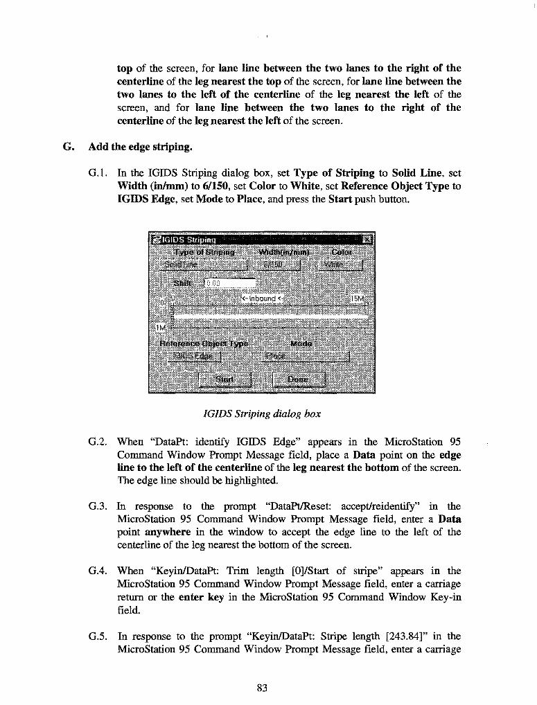
top of the screen, for lane line between the two lanes to the right of the centerline of the leg nearest the top of the screen, for lane line between the two lanes to the left of the centerline of the leg nearest the left of the screen, and for lane line between the two lanes to the right of the centerline of the leg nearest the left of the screen.
G. Add the edge striping.
G.l. In the IGIDS Striping dialog box, set Type of Striping to Solid Line, set Width (inlmm) to 6/150, set Color to White, set Reference Object Type to IGIDS Edge, set Mode to Place, and press the Start push button.
IGIDS Striping dialog box
G.2. When "DataPt: identify IGIDS Edge" appears in the MicroStation 95 Command Window Prompt Message field, place a Data point on the edge line to the left of the centerline of the leg nearest the bottom of the screen. The edge line should be highlighted.
G.3. In response to the prompt "DataPt/Reset: accept/reidentify" in the MicroStation 95 Command Window Prompt Message field, enter a Data point anywhere in the window to accept the edge line to the left of the centerline of the leg nearest the bottom of the screen.
G.4. When "Keyin!DataPt: Trim length [0]/Start of stripe" appears in the MicroStation 95 Command Window Prompt Message field, enter a carriage return or the enter key in the MicroStation 95 Command Window Key-in field.
G.5. In response to the prompt "Keyin/DataPt: Stripe length [243.84]" in the MicroStation 95 Command Window Prompt Message field, enter a carriage
83

return or the enter key in the MicroStation 95 Command Window Key-in field. A Solid Line of width 150 mm (5.9 in.) and color of White should appear on the edge line to the left of the centerline of the leg nearest the bottom of the screen.
G.6. Repeat steps G.2 through G.S for edge line to the right of the centerline of the leg nearest the bottom of the screen, for curb return line to the right of the centerline of the leg nearest the bottom of the screen, for edge line to the left of the centerline of the leg nearest the right of the screen, for edge line to the right of the centerline of the leg nearest the right of the screen, for curb return line to the right of the centerline of the leg nearest the right of the screen, for edge line to the left of the centerline of the leg nearest the top of the screen, for edge line to the right of the centerline of the leg nearest the top of the screen, for curb return line to the right of the centerline of the leg nearest the top of the screen, for edge line to the left of the centerline of the leg nearest the left of the screen, for edge line to the right of the centerline of the leg nearest the left of the screen, and for curb return line to the right of the centerline of the leg nearest the left of the screen.
H. Add the stop line striping.
H.l. In the IGIDS Striping dialog box, set Type of Striping to Solid Line, set Width (inlmm) to 18/450, set Color to White, set Reference Object Type to IGIDS Edge, set Mode to Place, and press the Start push button.
IGIDS Striping dialog box
H.2. When "DataPt: identify IGIDS Edge" appears in the MicroStation 95 Command Window Prompt Message field, place a Data point on the stop
84

line of the median lane to the right of the centerline of the leg nearest the bottom of the screen. The stop line should be highlighted.
H.3. In response to the prompt "DataPtiReset: accept/reidentify" in the MicroStation 95 Command Window Prompt Message field, enter a Data point anywhere in the window to accept the stop line of the median lane to the right of the centerline of the leg nearest the bottom of the screen.
H.4. When "Keyin!DataPt: Trim length [0]/Start of stripe" appears in the MicroStation 95 Command Window Prompt Message field, enter a carriage return or the enter key in the MicroStation 95 Command Window Key-in field.
H.5. In response to the prompt "Keyin/DataPt: Stripe length 3.60]" in the MicroStation 95 Command Window Prompt Message field, enter a carriage return or the enter key in the MicroStation 95 Command Window Key-in field. A Solid Line of width 300 mm (11.8 in.) and color of White should appear on stop line of the median lane to the right of the centerline of the leg nearest the bottom of the screen.
H.6. Repeat steps H.2 through H.S for stop line of the curb lane to the right of the centerline of the leg nearest the bottom of the screen, for stop line of the median lane to the right of the centerline of the leg nearest the right of the screen, for stop line of the curb lane to the right of the centerline of the leg nearest the right of the screen, for stop line of the median lane to the right of the centerline of the leg nearest the top of the screen, for stop line of the curb lane to the left of the centerline of the leg nearest the top of the screen, for stop line of the median lane to the right of the centerline of the leg nearest the left of the screen, and for stop line of the curb lane to the right of the centerline of the leg nearest the left of the screen.
H.7. In the IGIDS Striping dialog box, press the Done push button.
I. Set the viewing of the lane graphics off.
I.l. From the IGIDS Side Bar Menu, select VIEW->Lane->CURRENT OFF.
J. Create and review a traffic inventory report.
J.l. From the IGIDS Side Bar Menu, select TOOLS->Traffic->lnventory>Report.
1.2. In the IGIDS Inventory Report dialog box under Directories, make sure your "c:\igids" directory is selected, then under Files, enter "ex_strp," and fmally
85

press the OK push button. IGIDS will save the traffic inventory report to the file "ex_strp.txt."
J.3. In the MicroStation 95 Command Window Key-in field, enter "dr=c:\igids\ex_strp.txt" plus a carriage return or enter key. The traffic inventory report should be displayed in the c:\igids\ex_strp.txt dialog box.
J.4. Close the c:\igids\ex_strp.txt dialog box by pressing the "x" in the upperright comer of the dialog box.
c:'Jgids\ex_strp.txt dialog box
K. Save the MicroStation 95 design file settings.
K.l. Choose MicroStation 95 Flle->Save Settings.
L. Plot the drawing.
L.l. Choose MicroStation 95 File->Print/Plot. From the Plot dialog box, choose File->Preview. From the Plot Preview dialog box, choose Setup->Page. In the Print Setup dialog box, in the Printer group choose a Name, in the Orientation group choose Landscape, and press the OK push button. From the Plot Preview dialog box, choose File->Plot. Get your plot from the printer and check your plot. Close the Plot dialog box by selecting the "X" in the upper right comer.
86

Striping and Traffic Inventory Report Plot
M. Save the intersection to a database f':de for later use.
M.l. From the IGIDS Side Bar Menu, select SAVE TO->Data Base.
M.2. In the IGIDS Database File dialog box under Directories, make sure your "c:\igids" directory is selected, then under Flles, enter "ex_strp," and finally press the OK push button. IGIDS will save the intersection data to the file "ex_strp.dbs."
N. Exit IGIDS.
N.L From the IGIDS Side Bar Menu, select END IGIDS.
87

0. Exit MicroStation 95.
0.1. Choose MicroStation 95 File->Exit.
88

ADD LEG
Objective: Add a leg centerline, add two inbound and two outbound lanes, and add a curb lane curb return.
Activity: Load the Simple Example, rotate two legs to make room for a another leg, attach the Introduction to MicroStation 95 ftle as a reference file, add a leg centerline by identifying the graphics in the Introduction to MicroStation 95 file, add two inbound and two outbound lanes by key-in, and add a curb lane curb return by key-in.
Background: Intersection analysis begins by defining the geometry of the intersection. Several common intersections are available to load as a beginning step in the analysis process. The intersection may then be modified to fit the particular problem. Placing a standard intersection and then modifying the intersection is normally easier than creating an intersection from scratch. IGIDS objects may be added by identifying graphics on the scratch level or in a reference file and by key-in.
A. Start MicroStation 95 and create a 2D design file "ex_adleg.dgn" using the seed me ''train2d.dgn."
A.l. From the Windows NT Start Menu in the lower-left corner of the screen, choose Start->Programs->MicroStation95->MicroStation9S.
A.2. From the MicroStation 95 Manager dialog box, choose Style->Command Window.
A.3. From the MicroStation 95 Manager dialog box, choose File->New.
A.4. From the Create Design File dialog box, choose Select within the Seed File group.
A.5. From the Select Seed File dialog box under Directories, make sure your "c:\igids" directory is selected, then under Files, choose "train2d.dgn," and fmally press the OK push button.
A.6. From the Create Design File dialog box under Directories, make sure your "c:\igids" directory is selected, then under Files, enter "ex_adleg," and finally press the OK push button.
A.7. From the MicroStation 95 Manager dialog box under Directories, make sure your "c:\igids" directory is selected, then under Files, select "ex_adleg.dgn," and finally press the OK push button.
A.8. If a MicroStation 95 Restricted Use dialog box appears for Academic Edition, drag the MicroStation 95 Restricted Use dialog box off the screen.
89

B. Start IGIDS.
B.L In the MicroStation 95 Command Window Key-in field, enter "mdl load igids." Press the OK push button when the IGIDS Alert dialog box appears.
B.2. Drag the IGIDS Side Bar Menu to the upper-left comer of the MicroStation window.
C. Load the saved IGIDS database ex_ 4x4.dbs.
C.l. From the IGIDS Side Bar Menu, select LOADFROM->DATABASE.
C.2. In the Intersection database fllename dialog box under Directories, make sure your "c:\igids" directory is selected, then under Files, choose "ex_ 4x4.dbs," and finally press the OK push button.
C.3. In Window 1, press the Fit View icon. In Window 1, press the Zoom In icon, move the cursor in Window 1 so that the center of the zoom-in rectangle is near the center of the intersection and press the Data button.
D. Rotate the legs.
D.l. From the IGIDS Side Bar Menu, select ROTATE->Leg.
D.2. In response to the prompt "Keyin: rotation angle [1.0]" in the MicroStation 95 Command Window Prompt Message field, enter "15" plus a carriage return or enter key in the MicroStation 95 Command Window Key-in field. The leg nearest the top of the screen should be highlighted.
D.3. When "DataPt/Reset: accept & define dir. & rotate" appears in the MicroStation 95 Command Window Prompt Message field, place a Data point to the left of the highlighted leg in a location such that the perpendicular projection of the point falls on the highlighted centerline of the leg. IGIDS will rotate the leg 15.0 degrees counterclockwise and report statistics in the MicroStation 95 Command Window Inform Message field.
DA In response to the prompt "DataPt/Reset: define dir. & rotate/reidentify" in the MicroStation 95 Command Window Prompt Message field, enter a Reset button.
D.5. When "DataPt: identify Leg to rotate" appears in the MicroStation 95 Command Window Prompt Message field, place a Data point on the leg nearest the right of the screen.
D.6. In response to the prompt "DataPt/Reset: accept, define dir. & rotate/reidentify" in the MicroStation 95 Command Window Prompt
90

Message field, place a Data point below the highlighted leg in a location such that the perpendicular projection of the point falls on the highlighted centerline of the leg. IGIDS will rotate the leg 15.0 degrees clockwise and report statistics in the MicroStation 95 Command Window Inform Message field.
E. Attach the reference file "ex_intro.dgn" to the design file.
E.l. From the MicroStation 95 dialog box, choose File->Reference.
E.2. In the Reference Files: Design Files [0] dialog box, choose Tools-> Attach.
E.3. In the Attach Reference File dialog box under Directories:, make sure your "c:\igids" directory is selected, then under Files, select "ex_intro.dgn," and finally press the OK push button.
E.4. In the new Attach Reference File dialog box, set Logical Name to "ex_intro," set Description to "leg to add," set Attachment Mode to Coincident, deselect Scale Line Styles, and finally press the OK push button.
B.S. In the Reference Files: Design Files [1] dialog box, press the "X" in the upper right comer to close the dialog box. The graphics from Introduction to MicroStation 95 should be visible.
F. Add a leg centerline from the scratch level.
F.l. From the IGIDS Side Bar Menu, select ADD->LEG CNTRLN>SCRATCH L VL.
F.2. In response to the prompt "Keyin/Reset: Leg number/end command" in the MicroStation 95 Command Window Prompt Message field, enter "5" plus a carriage return or enter key in the MicroStation 95 Command Window Keyin field.
F.3. When "Keyin: CL station number at intersection center" appears in the MicroStation 95 Command Window Prompt Message field, enter "0" plus a carriage return or enter key in the MicroStation 95 Command Window Keyin field.
FA. In response to the prompt "Keyin: increasing or decreasing" in the MicroStation 95 Command Window Prompt Message field, enter "i" plus a carriage return or the enter key in the MicroStation 95 Command Window Key-in field.
91

F.5. When "Keyin: Leg description" appears in the MicroStation 95 Command Window Prompt Message field, enter "Leg 5" plus a carriage return or the enter key in the MicroStation 95 Command Window Key-in field.
F.6. In response to the prompt "DataPt: identify line or arc to add to Centerline" in the MicroStation 95 Command Window Prompt Message field, place a Data point on the line from the reference file closest to the intersection center. The line should be highlighted.
F.7. When "DataPt/Reset: accept and add to Centerline/reidentify" appears in the MicroStation 95 Command Window Prompt Message field, place a Data point on the arc from the reference file. The line should be added to the centerline and the arc should be highlighted.
F.8. In response to the prompt "DataPt/Reset: accept and add to Centerline/reidentify," place a Data point on the line from the reference file farthest from the intersection center. The arc should be added to the centerline and the line should be highlighted.
F.9. When" DataPt/Reset: accept and add to Centerline/reidentify" appears in the MicroStation 95 Command Window Prompt Message field, place a Data point anywhere in the window to accept the line. The line should be added to the centerline.
G. Add inbound lanes by key-in.
G.l. From the IGIDS Side Bar Menu, select ADD->LANE INBND->BY KEYIN.
G .2. In response to the prompt "DataPt/Reset: accept/reidentify" in the MicroStation 95 Command Window Prompt Message field, place a Data point anywhere in the window to accept the highlighted leg.
G.3. When "Keyin!Reset: no. new inb. Lanes [!]/reidentify" appears in the MicroStation 95 Command Window Prompt Message field, enter "2" plus a carriage return or enter key in the MicroStation 95 Command Window Keyin field.
G.4. In response to the prompt "Keyin: number of left turn bays [0]" in the MicroStation 95 Command Window Prompt Message field, enter a carriage return or the enter key in the MicroStation 95 Command Window Key-in field.
G.5. When "Keyin: number of right turn bays [0]" appears in the MicroStation 95 Command Window Prompt Message field, enter a carriage return or the enter key in the MicroStation 95 Command Window Key-in field.
92

G.6. In respdnse to the prompt "Keyin!DataPt: setback to beginning of Lanes" in the MicroStation 95 Command Window Prompt Message field, enter "0" plus a carriage return or enter key in the MicroStation 95 Command Window Key-in field.
G.7. When "Keyin!DataPt: distance from CL [0.00]" appears in the MicroStation 95 Command Window Prompt Message field, enter a carriage return or enter key in the MicroStation 95 Command Window Key-in field.
G.8. In response to the prompt "Keyin!DataPt: width of one Lane [3.6]/all Lanes," enter a carriage return or enter key in the MicroStation 95 Command Window Key-in field.
G.9. When "Keyin!DataPt: Lane length [285.75]" appears in the MicroStation 95 Command Window Prompt Message field, enter a carriage return or enter key in the MicroStation 95 Command Window Key-in field.
H. Add outbound lanes by key-in.
H.l. From the IGIDS Side Bar Menu, select ADD->LANE OUTBND->BY KEY-IN.
H.2. In response to the prompt "DataPt/Reset: accept/reidentify" in the MicroStation 95 Command Window Prompt Message field, place a Data point anywhere in the window to accept the highlighted leg.
H.3. When "Keyin/Reset: no. new outb. Lanes [!]/reidentify" appears in the MicroStation 95 Command Window Prompt Message field, enter "2" plus a carriage return or enter key in the MicroStation 95 Command Window Keyin field.
H.4. In response to the prompt "Keyin: number of right tum bays [0]" in the MicroStation 95 Command Window Prompt Message field, enter a carriage return or the enter key in the MicroStation 95 Command Window Key-in field.
H.5. When "Keyin!DataPt: setback to beginning of Lanes" appears in the MicroStation 95 Command Window Prompt Message field, enter "0" plus a carriage return or enter key in the MicroStation 95 Command Window Keyin field.
H.6. In response to the prompt "Keyin!DataPt: distance from CL [0.00]" in the MicroStation 95 Command Window Prompt Message field, enter a carriage return or enter key in the MicroStation 95 Command Window Key-in field.
93

H.7. When "Keyin/DataPt: width of one Lane [3.6]/all Lanes" appears in the MicroStation 95 Command Window Prompt Message field, enter a carriage return or enter key in the MicroStation 95 Command Window Key-in field.
H.8. In response to the prompt "Keyin!DataPt: Lane length [299.25]," enter a carriage return or enter key in the MicroStation 95 Command Window Keyin field.
I. Add a curb lane curb return by keyin.
I.l. From the IGIDS Side Bar Menu, select ADD->CURB CR->BY KEY-IN.
1.2. In response to the prompt "DataPt/Reset: accept/reidentify" in the MicroStation 95 Command Window Prompt Message field, place a Data point anywhere in the window to accept the highlighted leg.
I.3. When "Keyin!Reset: curb return radius (min=O.lOM)/reidentify" appears in the MicroStation 95 Command Window Prompt Message field, enter "6.1" plus a carriage return or enter key in the MicroStation 95 Command Window Key-in field.
J. Save the MicroStation 95 design rile settings.
J.l. Choose MicroStation 95 File->Save Settings.
K. Plot the drawing.
K.l. Choose MicroStation 95 File->Print!Plot. From the Plot dialog box, choose File->Preview. From the Plot Preview dialog box, choose Setup->Page. In the Print Setup dialog box, in the Printer group choose a Name, in the Orientation group choose Landscape, and press the OK push button. From the Plot Preview dialog box, choose File->Plot. Get your plot from the printer and check your plot. Close the Plot dialog box by selecting the "X" in the upper-right corner.
94

i
b-----------
I I I I
I : I I
I I I
I II I I
Add Leg Plot
L. Save the intersection to a database file for later use.
L.l. From the IGIDS Side Bar Menu, select SAVE TO->Data Base.
L.2. In the IGIDS Database File dialog box under Directories, make sure your "c:\igids" directory is selected, then under Files, enter "ex_adleg," and finally press the OK push button. IGIDS will save the intersection data to the file "ex_adleg.dbs."
M. Exit IGIDS.
M.l. From the IGIDS Side Bar Menu, select END IGIDS.
N. Exit MicroStation 95.
N.l. Choose MicroStation 95 File->Exit.
95

96

REFERENCES
1. Rioux, Thomas W ., Robert F. Inman, Charles H. Berry, Clyde E. Lee, and Randy B. Machemehl, "Interactive Graphics Intersection Design System: First Stage Development," Research Report 1139-1F, Center for Transportation Research, The University of Texas at Austin, Austin, Texas, November 1991.
2. Rioux, Thomas W ., Robert F. Inman, Randy B. Machemehl, and Clyde E. Lee, "Interactive Graphics Intersection Design User's Manual," Research Report 1308-1F, Center for Transportation Research, The University of Texas at Austin, Austin, Texas, December 1994.
3. Rioux, Thomas W ., Robert F. Inman, Randy B. Machemehl, and Clyde E. Lee, "Interactive Graphics Intersection Design System (IGIDS) Training Manual," Research Report Number 0-1291-1, Center for Transportation Research, The University of Texas at Austin, Austin, Texas, January 1998.
4. "MicroStation Customer Support Library Reference Manual," Version 4 for Clix, DOS, and MAC, Document DSYS11540, Bentley Systems, Inc. and Intergraph Corporation, 1990.
5. "MicroStation User's Guide," Version 4 for Clix, Document DGA051410, Bentley Systems, Inc. and Intergraph Corporation, 1991.
6. "MicroStation Reference Guide," Version 4 for Clix, Document DGA051710, Bentley Systems, Inc. and Intergraph Corporation, 1991.
7. "MicroStation MDL Manual," Version 4 for DOS, Document DGA022410, Bentley Systems, Inc. and Intergraph Corporation, 1991.
8. "MicroStation User's Guide," Version 5, Document DGA0514110, Bentley Systems, Inc. and Intergraph Corporation, September 1993.
9. "MicroStation Reference Guide," Version 5, Document DGA054210, Bentley Systems, Inc. and Intergraph Corporation, September 1993.
10. "MicroStation Development and Support Guide," Version 5, Document DGA054310, Bentley Systems, Inc. and Intergraph Corporation, September 1993.
11. "MicroStation MDL Programmer's Guide," Version 5, Document DGA055010, Bentley Systems, Inc. and Intergraph Corporation, November 1993.
12. "MicroStation MDL Function Reference Manual," Version 5, Document DGA055110, Bentley Systems, Inc. and Intergraph Corporation, December 1993.
97

13. "MicroStation 95 Academic Suite PC Setup Guide," Bentley Systems, Inc., 1995.
14. "MicroStation 95 Academic Suite Upgrade Guide," Bentley Systems, Inc., 1996.
15. "MicroStation 95 Academic Suite User's Guide," Bentley Systems, Inc., 1995.
16. Lee, Clyde E., Thomas W. Rioux, and CharlieR. Copeland, "The TEXAS Model for Intersection Traffic -Development," Research Report 184-1, CFHR 3-18-72-184-1, Center for Highway Research, The University of Texas at Austin, Austin, Texas, December 1977.
17. Lee, Clyde E., Thomas W. Rioux, Vivek S. Savur, and Charlie R. Copeland, "The TEXAS Model for Intersection Traffic- Programmer's Guide," Research Report 184-2, CFHR 3-18-72-184-2, Center for Highway Research, The University of Texas at Austin, Austin, Texas, December 1977.
18. Lee, Clyde E., Glenn E. Grayson, CharlieR. Copeland, Jeff W. Miller, Thomas W. Rioux, and Vivek S. Savur, "The TEXAS Model for Intersection Traffic - User's Guide," Research Report 184-3, CFHR 3-18-72-184-3, Center for Highway Research, The University of Texas at Austin, Austin, Texas, July 1977.
19. Rioux, Thomas W., and Clyde E. Lee, "TEXAS- A Microscopic Traffic Simulation Package for Isolated Intersections," 56th Annual Meeting of the Transportation Research Board, Washington, D.C., January 1977, and Transportation Research Record 644, 1977, pages 45-51.
20. Lee, Clyde E., Robert F. Inman, and Wylie M. Sanders, "User-Friendly TEXAS Model -Guide to Data Entry," Research Report 361-1F, CTR 3-18-84-361-1F, Center for Transportation Research, The University of Texas at Austin, Austin, Texas, November 1985.
21. Lee, Clyde E., Randy B. Machemehl, and Wiley M. Sanders, "TEXAS Model Version 3.0 (Diamond Interchanges)," Research Report 443-1 F, Center for Transportation Research, The University of Texas at Austin, Austin, Texas, January 1989.
22. Rioux, Thomas W., "Simulation of Diamond Interchange Traffic Operations," 70th Annual Meeting of the Transportation Research Board, Washington, D.C., January 1991.
23. Rioux, Thomas W., Robert Inman, Randy B. Machemehl, and Clyde E. Lee, "Texas Model for Intersection Traffic- Additional Features," Research Report 1258-1F, CTR 3-18-91/2-1258-1F, Center for Transportation Research, The University of Texas at Austin, Austin, Texas, January 1993.
98

24. "SOAP84 User's Manual," FHWA-IP-85-7, Federal Highway Administration, U. S. Department of Transportation, January 1985.
25. "SOAP84 Data Input Manual," FHW A-IP-85-8, Federal Highway Administration, U.S. Department of Transportation, January 1985.
26. "Supplement to SOAP84 User's Manual," FHWA-IP-85-7, Transportation Research Center, University of Florida, Gainesville, Florida, September 1988.
27. A Policy on Geometric Design of Highways and Streets 1990, American Association of State Highway and Transportation Officials (AASHTO), 1990.
28. A Policy on Geometric Design of Highways and Streets 1994, American Association of State Highway and Transportation Officials (AASHTO), 1994 (Metric).
29. 1980 Texas Manual on Uniform Traffic Control Devices for Streets and Highways, Texas State Department of Transportation, Austin, Texas, 1980, with Revision 6, 1996.
30. Highway Capacity Manual Special Report 209, Transportation Research Board, National Research Council, Washington, D.C., Third Edition, 1994.
31. "Vehicle Turning Characteristics For Use In Geometric Design," Geometric Design Section, Highway Design Division, State Department of Highways and Public Transportation, Austin, Texas, 1987.
32. "GEOPAK," GEOPAK Corporation, North Miami Beach, Florida, 1996.
33. "McTrans Newsletter," Center for Microcomputers in Transportation, Transportation Research Center, University of Florida, Gainesville, Florida, 1997.
99

100

APPENDIX
The following presents the Microsoft PowerPoint slides delivered with the Training Manual.
101

102
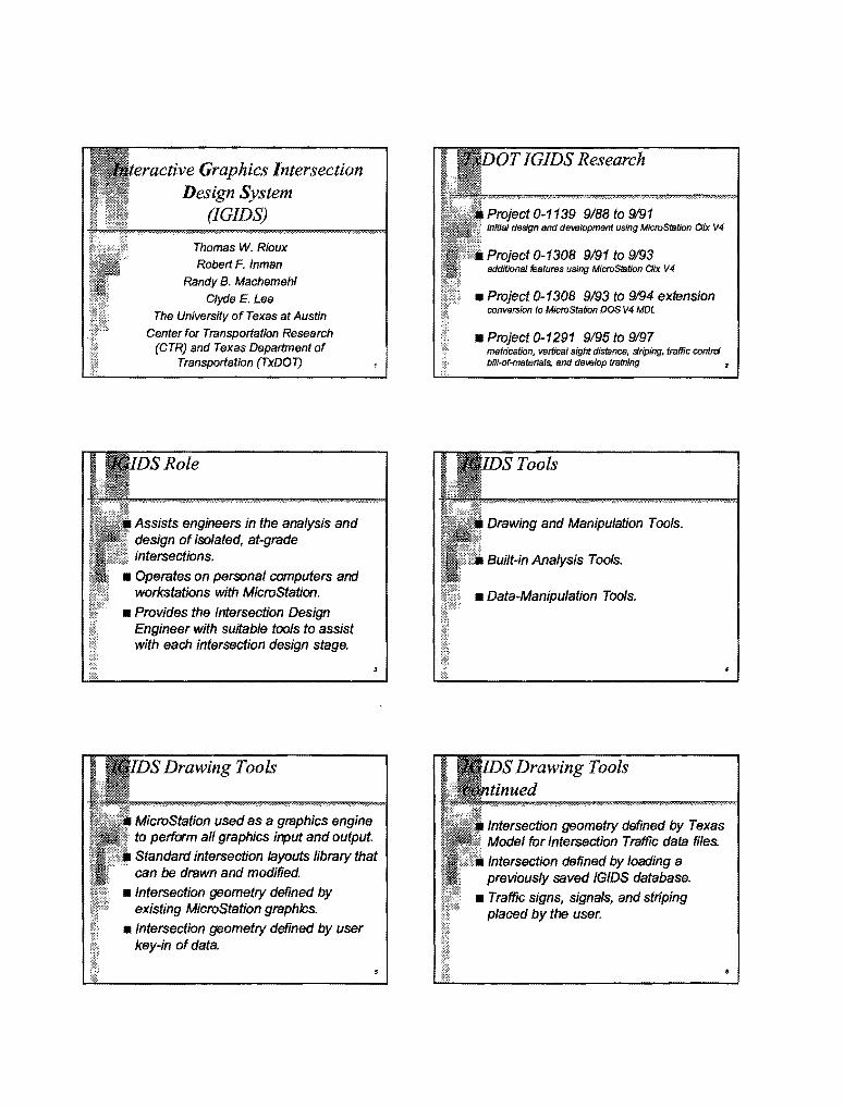
Graphics Intersection Design System
(IGIDS)
Thomas W. Rioux
Robert F. Inman
Randy B. Machemehl
Clyde E. Lee
The University of Texas at Austin
Center for Transportation Research (CTR) and Texas Department of
Transportation (TxDOT)
Role
Assists engineers in the analysis and design of isolated, at-grade intersections.
• Operates on personal computers and workstations with MicroStation.
• Provides the Intersection Design Engineer with suitable tools to assist with each intersection design stage.
Drawing Tools
MicroStation used as a graphics engine to perform all graphics input and output.
Standard intersection layouts library that can be drawn and modified.
• Intersection geometry defined by existing MicroStation graphics.
• Intersection geometry defined by user key-in of data.
IGIDS Research
Project 0-1139 9188 to 9191 Initial design and development using MicroStatJon 0/x V4
Project 0-1308 9/91 to 9/93 additional features using M/croStation Oix V 4
• Project 0-1308 9193 to 9194 extension conversion to MicroStafion DOS V4 MDL
• Project 0-1291 9/95 to 9197 metrication, vertical sight distance, striping, traffic control bill-of-materials, and deveiop training
Tools
Drawing and Manipulation Tools.
Built-in Analysis Tools.
• Data-Manipulation Tools.
Intersection geometry defined by Texas Model for Intersection Traffic data files.
Intersection defined by loading a previously saved IGIDS database.
• Traffic signs, signals, and striping placed by the user.
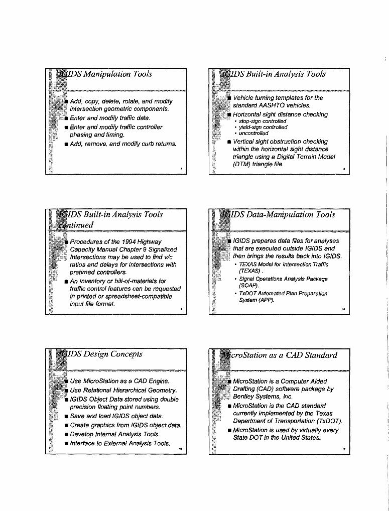
Manipulation Tools
Add, copy, delete, rotate, and modify intersection geometric components.
Enter and modify traffic data.
• Enter and modify traffic controller phasing and timing.
• Add, remove, and modffy curb returns.
Procedures of the 1994 Highway Capacity Manual Chapter 9 Signalized Intersections may be used to find vic ratios and delays for intersections with pretimed controllers.
• An inventory or bill-of-materials for traffic control features can be requested in printed or spreadsheet-compatible input file format.
Design Concepts
Use MicroStation as a CAD Engine.
Use Relational Hierarchical Geometry.
IGIDS Object Data stored using double precision floating point numbers.
• Save and load IGIDS object data.
• Create graphics from IGIDS object data.
• Develop Internal Analysis Tools.
•Interface to External Analysis Tools. 11
Built-in Analysis Tools
Vehicle turning templates for the standard AASHTO vehicles.
Horizontal sight distance checking • stop-sign controlled • yield-sign controlled • uncontrolled
• Vertical sight obstruction checking within the horizontal sight distance triangle using a Digital Te"ain Model (DTM) triangle file.
Data-Manipulation Tools
IGIDS prepares data files for analyses that are executed outside IGIDS and then brings the results back into IGIDS. • TEXAS Model for Intersection Traffic
(TEXAS).
• Signal Operations Analysis Package (SOAP).
• TxDOT Automated Plan Preparation System (APP).
••
croStation as a CAD Standard
MicroStation is a Computer Aided Drafting (CAD) software package by Bentley Systems, Inc.
• MicroStation is the CAD standard cu~ntly implemented by the Texas Department of Transportation (TxDOT).
• MicroStation is used by virtually every State DOT in the United States.

Microstation is used world wide.
Many operating systems and hardware platforms are supported.
• Provides drawing and plotting tools.
• Provides dialog box interface.
• User can switch between IGIDS commands and MicroStation commands.
DOS/Windows: Microstation Versions 4, 5, and 95
• Windows 95 and Windows NT: MicroStation Versions 5 and 95
• Clix: MicroStation Versions 4 and 5
Hierarchical Geometry
13
Relational: the single absolute coordinate is the center of the intersection; all geometric definitions are relative to parent object.
• Hierarchical: the parent/child relationships are maintained by IG/DS; all commands are automatically processed by IGIDS for child objects.
17
as a CAD Engine
IGIDS uses MicroStafion to perform all interactive graphics operations, to maintain the graphics engine database, and to perform all plotting functions.
• IGIDS software operates above and drives the graphics engine through a higher-/eve/language interface.
• /GIDS allows the user to switch easily between executing /GIDS commands and graphics engine commands. ..
Units
English or Metric units. • IGIDS units are automatically determined
by design file master units specifications. • Once a project has been started in a given
system of units, the system of units may not be changed.
• 2D or 3D design file. • 2D for virtually all functions. • 3D for vertical sight distance checking. • Easy to convert between 2D and 3D.
Hierarchical Objects
Intersection
,.
list of alternatives and intersection data.
• Alternative (maximum of 15) list of legs, list of text, and alternative data.

Leg list of centerline segments, inbound lanes, outbound lanes, inner edge curb return segments, and outer edge curb return segments and leg data.
Leg (enlarged)
Text on Alternative
,.
Leg Centerline
..

list of inner edge segments, outer edge segments, stop line segments, inner edge striping segments, outer edge striping segments, stop line striping segments, and other striping segments and lane data.
Hierarchical Objects tinued
Segment (arc or line) list of text and segment data.
Lane Outer Edge Segment
..
Lane Inner Edge Segment
Stop Line Segment
..
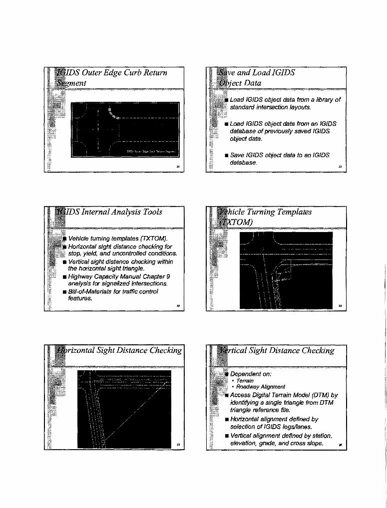
Outer Edge Curb Return
Internal Analysis Tools
Vehicle turning templates (TXTOM). Horizontal sight distance checking for stop, yield, and uncontrolled conditions.
• Vertical sight distance checking within the horizontal sight triangle.
• Highway Capacity Manual Chapter 9 analysis for signaHzed intersections.
• Bill-of-Materials for traffic control features.
Data
Load IGIDS object data from a library of standard intersection layouts.
• Load IGIDS object data from an IGIDS database of previously saved IG/DS object data.
• Save IG/DS object data to an IGIDS database.
Sight Distance Checking
Dependent on: • Terrain • Roadway Alignment
Access Digital Terrain Model (DTM) by identifying a single triangle from DTM triangle reference file.
• Horizontal alignment defined by selection of IGIDS legs/lanes.
• Vertical alignment defined by station, elevation, grade, and cross slope.
..
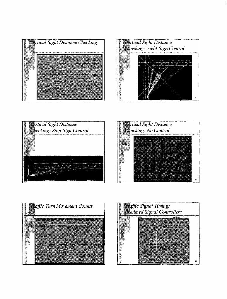
Sight Distance Checking
Sight Distance ecJa:ng: Stop-Sign Control
Tum Movement Counts
Sight Distance Control
Sight Distance ·No Control
Signal Timing: Signal Controllers

Signal Timing: Signal Controllers
Capacity Manual 9: VIC Ratio
VIC Ratio
• solid line, broken line, dotted line, lane drop, no passing inbound, no passing outbound, double solid line, and double broken line .
• Width
• 4, 6, 8, 12, 18, and 24 inches. • 100, 150, 200, 300, 450, and 600mm.
• Color • white and yellow.
n
Stopped Delay
...
• Stop and Yield.
• Pretimed and NEMA Controllers.
• Traffic Signal Heads.
• Pavement Markings • Striping.
• Traffic Control Features Bill-of-Materia@

- 3 Jen., pzvteete11e1t Chru~eb'uU~ - <e;< Ctmt:rc.ller - P:rmt:iloed si:<B 1 C14ume.H::at.ion !tight Ch.mnaJ.l;r&Uon Sl:r&ight;
!SO lllll1 ~thite 2926. Oe N J.50 lllll1 yell"" 975.36 H
450 """' ~thJte
External Analysis Tools
IGIDS builds input to external analysis tool for execution outside IGIDS and may retrieve output results for processing within IGIDS
• Texas Model for Intersection Traffic
• Signal Operations Analysis Package
• TxDOT Automated Plan Preparation System
Tabular Report
Spreadsheet Importable File.
•sc.,;pi,,g•,•'Do"'"• Sclld Ltnc•,"150",~""'~, ~yelloor", "'!J75.3fi",~H" :;,tn•~."450~, .._ .. , "~thite " 1 ~43.20~, "N"
~Ch:ilnfleJ..i.zation Left~, "4" ~.;:cmtrol.ler- l'ret1ll!ed • 41ize 1",'"J"' n.;:hA:lllel-1rat:lon 1'1:itJ.~t"'~"'4"'
"'Chann<>l:lz-.at.>:on 1/t:rn.ight~, ~4 ~
IGIDS Training Manual • Beginners and advanced exercises.
• Self-Paced.
• Printed and World Wide Web formats.
• Microsoft PowerPoint presentation.
50
..

Availability
ftp://ftp. ce. utexas.edulftp/igids or ftp. ce. utexas.eduligids • documentation (most but not an chapters)
• doslustn40
• doslustn50
• doslustn95
• winntlustn50
• winntlustn95
• McTrans in the future ..
5T