Embed Size (px)
Citation preview
Interactive Mesh Sculpting
Using a Haptic Device
by
Rodolfo Ortiz Magdaleno
A project submitted to the Graduate Faculty of the
University of Colorado at Colorado Springs
in partial fulfillment of the
requirements for the degree of
Master of Science
Department of Computer Science
2007
ii
This project for the Master of Science degree by
Rodolfo Ortiz Magdaleno
has been approved for the
Department of Computer Science
by
________________________________________________
Sudhanshu K. Semwal, Chair
________________________________________________
C. Edward Chow
________________________________________________
Keith Phillips
____________________
Date
iii
Ortiz Magdaleno, Rodolfo (M.S., Computer Science)
Interactive Mesh Sculpting Using a Haptic Device
Project directed by Professor Sudhanshu K. Semwal
3D meshes are widely used for modeling in videogames, movies and virtual reality
applications. A method to continuously sculpt or deform –these terms are used
interchangeably- a planar mesh using haptic interaction is implemented. Moreover, this
mesh has an image of the final model mapped on. The goal is to give the user the feeling
he or she is sculpting an image, thus making it easier to achieve the final model. A 3D
model is also shown as a reference so that the user knows how the final mesh should look
like. The mesh will also be smoothened using a NURBS surface to generate the 3D
model.
iv
CONTENTS
CHAPTER
I. INTRODUCTION ...............................................................................................1
Force Feedback Foundation...............................................................................2
II. PREVIOUS WORK.............................................................................................3
Force feedback device.......................................................................................3
Mesh sculpting..................................................................................................5
Force feedback device and modeling.................................................................6
III. DESIGN...............................................................................................................8
Haptic Device ...................................................................................................8
NURBS.............................................................................................................8
Particle System ...............................................................................................11
Runge-Kutta 4.................................................................................................12
Lips 3D model ................................................................................................14
IV. IMPLEMENTATION .......................................................................................15
Haptic Device .................................................................................................15
HLAPI and OpenGL .................................................................................16
HLAPI Basics ...........................................................................................17
Programming Details ......................................................................................17
Data Structures and Class Design ..............................................................17
Vertex Class ..............................................................................................18
v
Particle System Class ................................................................................18
Application Framework.............................................................................18
Purpose .....................................................................................................18
Third party software ..................................................................................19
Features of the implementation........................................................................19
Brush.........................................................................................................19
Show/Hide Particles ..................................................................................20
Rotations ...................................................................................................21
Extrude......................................................................................................21
3D Lips Model ..........................................................................................22
3D Paint ....................................................................................................22
3D Cursor..................................................................................................23
Force Feedback .........................................................................................23
Implementation details ....................................................................................23
Basic algorithm .........................................................................................23
Major issues ..............................................................................................24
V. RESULTS..........................................................................................................26
Comparing the Haptic Device and the Mouse..................................................26
Mapping Haptic Device to Graphics Simulation..............................................27
NURBS in OpenGL ........................................................................................27
Features of the implementation........................................................................28
Interactive sculpting ........................................................................................29
Lips sculpting..................................................................................................31
vi
Comparing Force Feedback and No Force Feedback .......................................42
VI. CONCLUSION..................................................................................................52
VII. FUTURE WORK..............................................................................................54
Editing Tools ..................................................................................................54
NURBS limitations .........................................................................................54
Different Views...............................................................................................54
Haptic Workspace ...........................................................................................55
3D paint ..........................................................................................................55
Adding knots on the fly...................................................................................55
Integration with image editing software...........................................................56
Image recognition ...........................................................................................56
VIII. BIBLIOGRAPHY .............................................................................................58
A. CONFIGURATION/INSTALLATION ............................................................60
Installation requirements .................................................................................60
Compilation procedures ..................................................................................60
Running the software ......................................................................................61
B. USER GUIDE/DEMO........................................................................................62
Getting started.................................................................................................62
Using the application.......................................................................................63
Rules of thumb................................................................................................63
vii
FIGURES
Figure
Figure 1. Blending functions for NURBS ......................................................................10
Figure 2. Blending functions using the knot vector {0,0,0,0,1,1,1,1}..............................11
Figure 3. Haptic Device from Sensable ..........................................................................15
Figure 4. Demonstrating the brush feature .....................................................................20
Figure 5. Simple painting example.................................................................................22
Figure 6. Showing the haptic device workspace .............................................................24
Figure 7. OpenGL has different coordinate systems .......................................................27
Figure 8. Generation of a deformation step by step ........................................................31
Figure 9. Initial flat image as a mesh..............................................................................32
Figure 10. Initial image showing the 3D lips model -only the control points- .................33
Figure 11. The first deformation is on the lower lip........................................................34
Figure 12. The second deformation is on the upper lip ...................................................35
Figure 13. Showing a different angle after sculpting the lips ..........................................36
Figure 14. Simulating an error while sculpting the mesh................................................37
Figure 15. The previous error is fixed by pushing the mesh ...........................................38
Figure 16. Final image showing the control points-side view-........................................39
Figure 17. Final image -front view- ...............................................................................40
Figure 18. Final image -front view- ...............................................................................41
viii
Figure 19. The lips model using the haptic feedback is more accurate............................43
Figure 20. There are differences between the front views in this case.............................44
Figure 21. Big models -when compared to the size of the mesh- are difficult to model...45
Figure 22. The model of a finger is very realistic ...........................................................46
Figure 23. Models with sharp edges are difficult to create..............................................47
Figure 24. A mouse can be modeled relatively quickly ..................................................48
Figure 25. The shadows in the original image enhance the realism.................................49
Figure 26. The next step would be modeling the back of the object................................50
CHAPTER I
INTRODUCTION
Generating 3D models by sculpting a mesh has been a research topic in the area of
computer graphics. It is still a process that is time consuming. Maybe we want to model a
face, but it is difficult to create a good model if we have not studied the exact shape of a
face. Or maybe we want to model a mountain shape but unless we know exactly how it
looks like, it is going to be difficult to come up with an accurate model.
By providing visual references and haptic interaction good results can be achieved.
The first visual reference will be an image mapped on a planar mesh or surface. The
second visual reference will be a 3D model of the image so that the user knows how the
sculpted mesh would look like. The haptic interaction will be done with a Phantom Omni
Basic Haptic Device. Instead of generating a polygonal mesh, a NURBS surface is used
as it has the appearance of more smoothness.
Our work is different than digitization because it provides artistic results. Digitization
can only be done in the laboratory using equipment like 3D scanners. On the other hand,
we are creating our models using human interaction.
Chapter II illustrates theories in the areas of the haptic interface, mesh sculpting and
modeling using the haptic device. Chapter III describes the design and foundation of the
methods chosen to do mesh sculpting in this project. Chapter IV explains the
implementation of the project, including the C++ libraries, data structures, class design
2
and programming details. Chapter V discusses the results and presents sample images of
the simulation. Chapter VI includes the final summary for this project. Chapter VII
discusses ideas for future work.
Force Feedback Foundation
Haptic is a term related to the sense of touch. Haptic technology refers to an
application that allows the user to interact with it by applying and receiving forces. The
haptic device is used to achieve this. It consists of a mechanical arm connected to a
motor. The user grabs it, and can move a cursor in 3 dimensions by manipulating the arm,
which has 6 degrees of freedom.
A haptic device, also known as force feedback device, is a technology that allows the
user to interact with computer applications using the sense of touch. By using it, the user
can manipulate three-dimensional virtual objects. It provides a specific API to create
applications that communicate with it. This API is an extension of the OpenGL API for
graphics.
Haptic programming is a form of rendering that produces forces to be displayed by a
haptic device [Sen05]. At the same time, the current areas of application include:
• Medical training
• Sculpting
• Videogames
• Assistive technology for the visually impaired
3
CHAPTER II
PREVIOUS WORK
Many approaches exist to achieve 3D modeling. Some approaches are based on
manipulating control points and other approaches include the haptic device. The next
sections present work done in the areas of mesh sculpting, haptic interaction, and mesh
sculpting using the haptic device.
Force feedback device
Again, the haptic device has been used for different purposes. In [ORC06] a method
for haptic interaction between rigid bodies is specified, where an existing 3-degree of
freedom (DOF) method is extended to 6 DOF. Besides, the method prevents any
interpenetration between virtual objects, which gives a god-object1 precise contact with
surfaces. This is the solution to the pop-through effect where the cursor of the haptic
device traverses objects, reducing the perception of detailed geometries according to
[ORC06].
The method above improves the haptic perception of objects. This is especially
important if we want to work with objects that have a high resolution and can not be
digitized exactly.
1 A god-object is “an idealized representation of the position of the haptic device that is constrained on the surfaces of the obstacles” [ORC06].

4
Another application of the haptic device is related to painting in Virtual
Environments. In [JTKN99] a haptic device is used to paint textures into NURBS
models. They state that the “main feature of the system is its simplicity”. In fact, the
usability of a Virtual Environment depends on whether it mimics the real process. This
idea not only applies to this painting system, but also to modeling and sculpting virtual
environments. This will be an important part of the project –mimicking the real sculpting
process-.
In [IYUM04] a haptic interface is used in a completely different way. It is used to
provide sense of taste by inserting it into the mouth. The device applies a force when the
user bites it to simulate the food texture. Still, more common applications are related to
surgical training. In [AGGZ03] a haptic device is used to provide “real-time haptic and
visual feedback during a virtual bone dissection simulation”. Other applications for
medical training can be found in [SEJL04].
A different way to use the haptic device is suggested in [PNCD01]. They suggest
using the haptic device for teleoperation of objects. They also provide different views of
the same scene. According to the results, different views do not improve performance
with the belief that “training and experience could improve it” using multiple different
views. This seems obvious if we consider that we need to switch between the different
views continuously.
Haptic touching of images has also been suggested. In [SP97] this is achieved by
constructing a 3D model from several 2D stereo images. However, it is limited because
detailed textures are hardly perceived. Still, this is a good example of how the haptic
device can be used to touch 3D objects.
5
Mesh sculpting
Quite a bit of research has been done in this area. Existing approaches include 3D
scanners, CAD tools and deformation using a set of reference points to modify a shape.
This last approach is probably one of the most studied methods for mesh deformation. It
works by using reference points to induce deformation. The Free Form Deformation
technique [SP86] is one example. It was introduced more than 20 years ago and many
modifications to it have been suggested. It basically uses trivariate Bernstein polynomials
to deform space. This method is based on using control points as already mentioned and
surface patches too. The control points define the vertices of a parallelepiped which
contains the surface to be deformed. When we move a control point the shape of the
parallelepiped changes and so the objects inside, accordingly to defined formulae.
Moreover, one special type of Free Form Deformation (FDD) allows the deformed shape
to preserve its volume after deformations.
This method has advantages:
a) it can be applied either locally or globally in the surface
b) it can also be used on both polygonal and solid models.
However, when doing local deformations we need to take into account the continuity
of the surface if we are using FFD. Moreover, using control points can be cumbersome
since we do not know for sure what mesh deformation we will obtain when manipulating
them. Free Form Deformation also relies on trivariate Bernstein polynomials which are
costly operations.
In [LF03] mesh deformation is achieved by “painting” directly into a model. In this
6
method, the focus is on providing direct control of the model’s shape instead of using
control points as the Free Form Deformation technique. The advantages are:
a) surface velocity is an intuitive way to deform a shape
b) it is based on local deformations
c) deforming the surface is easier to understand than moving the control points
“Painting” the surface means drawing over it. The deformations are achieved by
setting the velocity of the surface as a function of its paint. This application takes a shape
similar to the final model and starts deforming it. Complex shapes can be obtained as
long as the original model is complex.
Force feedback device and modeling
Only a few novel approaches as in [MQW01] and [CA06] provide interaction using a
haptic device. The first one uses subdivision solids to sculpt a mesh. The results are not
visually realistic but more like a cartoon. However, the mesh does respond to applied
forces through the haptic device. The user interface for this application provides different
sets of tools like haptic tools, geometric and topological tools, physics based tools and
artistic tools. This method subdivides the mesh using a predefined number of
subdivisions. Each resulting subdivided solid has attributes like damping, mass and
stiffness.
The second approach [CA06] creates highly realistic models using virtual clay.
Moreover, it provides quick prototyping. In fact, virtual clay offers several advantages
over real clay, although the first one is more commonly used in modeling. It is interesting
7
to notice that the clay is “environment mapped2 so that the user can better appreciate the
shape”. Another interesting feature is the undo/redo operation. This way the user can
experiment different operations on the clay and he or she can always go back to a
previous shape.
In [FOL02] a technique for 3D model design is presented. The idea is to apply
textures onto 3D meshes. It is interesting to see the possibility of using images instead of
textures in this application. According to [FOL02] this system and the haptic device
allowed “users with little or no experience on painting systems to create interesting
models with little training”. The user experiences include: adding force models is an
improvement and detecting and maintaining contact with the model is easier using the
haptic device.
2 Environment mapping is a technique where an object reflects its surroundings. To achieve this, the environment is projected in a 3D closed surface that surrounds the object.

8
CHAPTER III
DESIGN
This section explains the design for this project. Also, this section contains an
explanation of some of the methods used to develop this project.
Haptic Device
Many of the applications that sculpt 3D meshes use the mouse to work in a 3D
environment. This can cause errors since a 3D mesh has a depth Z. The mouse does not
work well in 3D as it is a 2D relative device. Our project uses the haptic device to enforce
movement in 3 dimensions and to touch a mesh - since the haptic device provides this
configuration-. It also gives the user force feedback when he or she touches the mesh. It
does have a limitation, and although it does not represent a problem in our project, it can
affect other applications: the device has a limited range of motion.
NURBS
NURBS stand for Nonuniform rational B-splines. They have advantages over Bezier
and Hermite surfaces:
a) They are invariant after perspective transformations. In other words, any
perspective transformation only needs to be applied to the control points.
b) We do not need to worry about loss of continuity between control points.
9
For this project, the NURBS surface is processed and created using GLU –an
OpenGL extension- specific instructions. These instructions draw a NURBS surface
based primarily on the control points and a knot array. Finally, NURBS act more
intuitively when rendering a large number of control points.
OpenGL also provides automatic texture mapping on the NURBS surface. In order to
achieve this, we evenly divide the image by the number of control points. Then, OpenGL
automatically positions the image on the mesh.
We will explain some important concepts about NURBS in general and also related to
OpenGL:
a) It is defined by its control points, knots and degree.
b) Sometimes the order of the curve is also referenced. The order and the degree
have the following relationship: order = degree + 1.
c) The relationship between number of control points and knots is the following:
#knots = #control_points + degree + 1
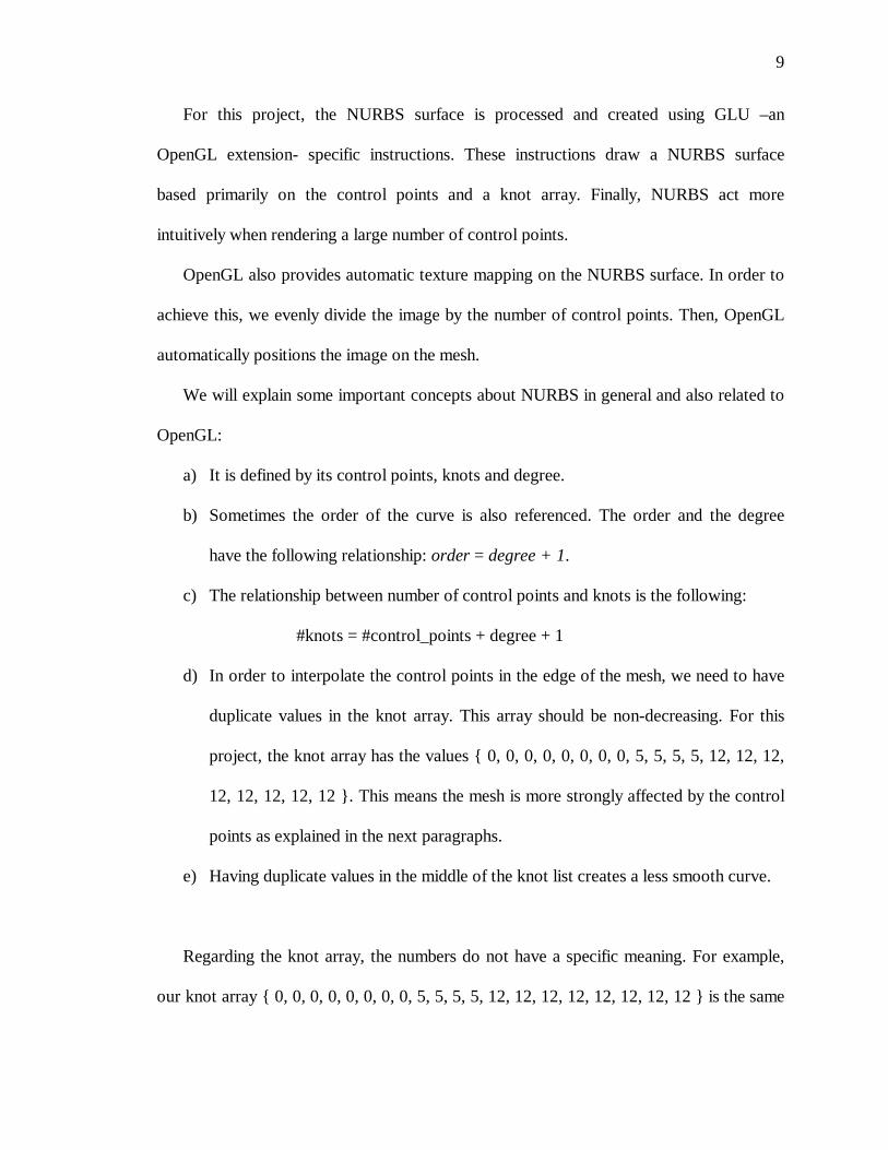
d) In order to interpolate the control points in the edge of the mesh, we need to have
duplicate values in the knot array. This array should be non-decreasing. For this
project, the knot array has the values { 0, 0, 0, 0, 0, 0, 0, 0, 5, 5, 5, 5, 12, 12, 12,
12, 12, 12, 12, 12 }. This means the mesh is more strongly affected by the control
points as explained in the next paragraphs.
e) Having duplicate values in the middle of the knot list creates a less smooth curve.
Regarding the knot array, the numbers do not have a specific meaning. For example,
our knot array { 0, 0, 0, 0, 0, 0, 0, 0, 5, 5, 5, 5, 12, 12, 12, 12, 12, 12, 12, 12 } is the same
10
as { 0, 0, 0, 0, 0, 0, 0, 0, 1, 1, 1, 1, 2, 2, 2, 2, 2, 2, 2, 2 }. What is important is the
difference between successive knot values. This is because that difference defines the
blending functions. And those blending functions define how the NURBS surface is
created. Moreover, each NURBS segment will have different blending functions
depending on the values of the knot array.
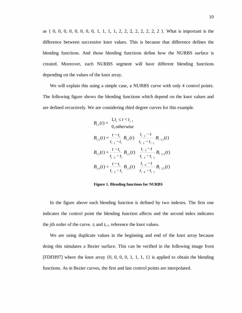
We will explain this using a simple case, a NURBS curve with only 4 control points.
The following figure shows the blending functions which depend on the knot values and
are defined recursively. We are considering third degree curves for this example.
)()()(
)()()(
)()()(
,0
,1)(
3,1
14
4
3,
3
4,
2,1
13
3
2,
2
3,
1,1
12
2
1,
1
2,
1
1,
tBtt
tttB
tt
tttB
tBtt
tttB
tt
tttB
tBtt
tttB
tt
tttB
otherwise
ttttB
i
ii
i
i
ii
ii
i
ii
i
i
ii
ii
i
ii
i
i
ii
ii
ii
i
+
++
+
+
+
++
+
+
+
++
+
+
+
−
−+
−
−=
−
−+
−
−=
−
−+
−
−=
<≤
=
Figure 1. Blending functions for NURBS
In the figure above each blending function is defined by two indexes. The first one
indicates the control point the blending function affects and the second index indicates
the jth order of the curve. ti and ti+1 reference the knot values.
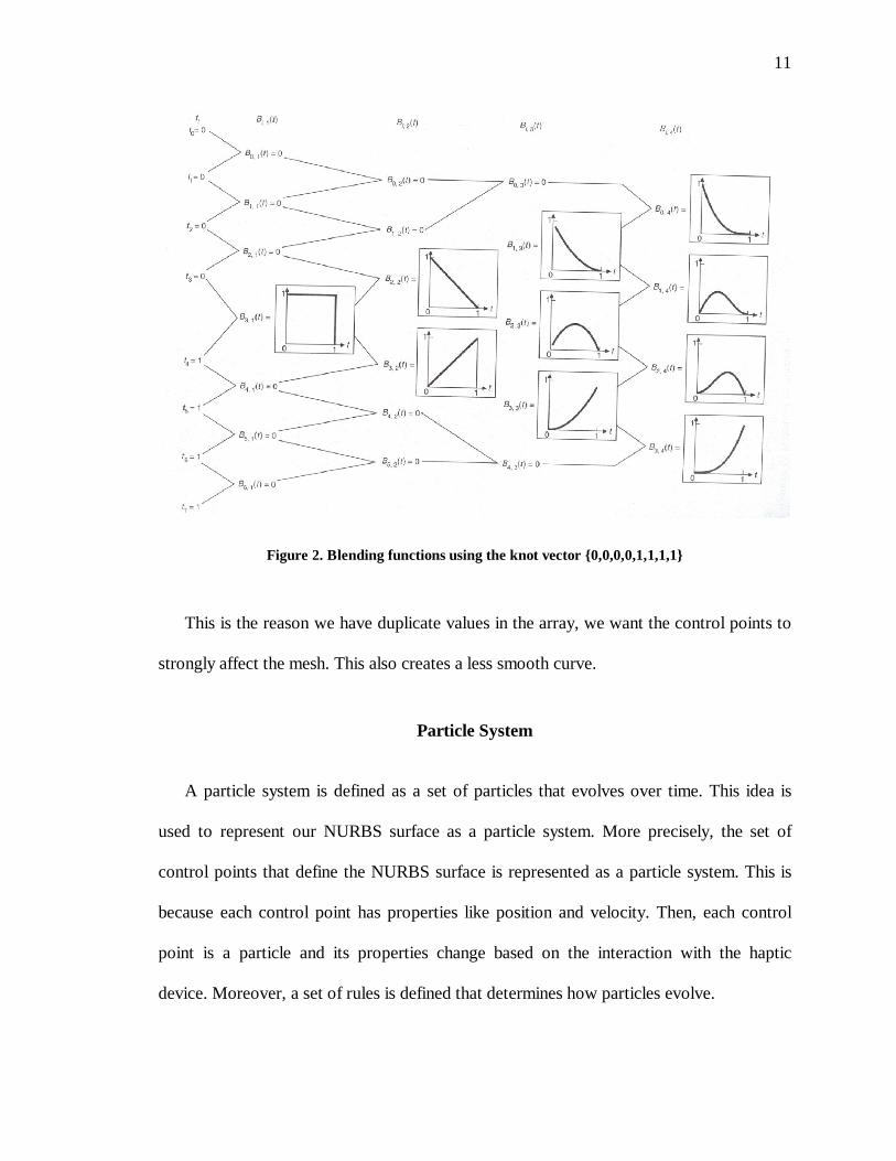
We are using duplicate values in the beginning and end of the knot array because
doing this simulates a Bezier surface. This can be verified in the following image from
[FDFH97] where the knot array {0, 0, 0, 0, 1, 1, 1, 1} is applied to obtain the blending
functions. As in Bezier curves, the first and last control points are interpolated.
11
Figure 2. Blending functions using the knot vector {0,0,0,0,1,1,1,1}
This is the reason we have duplicate values in the array, we want the control points to
strongly affect the mesh. This also creates a less smooth curve.
Particle System
A particle system is defined as a set of particles that evolves over time. This idea is
used to represent our NURBS surface as a particle system. More precisely, the set of
control points that define the NURBS surface is represented as a particle system. This is
because each control point has properties like position and velocity. Then, each control
point is a particle and its properties change based on the interaction with the haptic
device. Moreover, a set of rules is defined that determines how particles evolve.
12
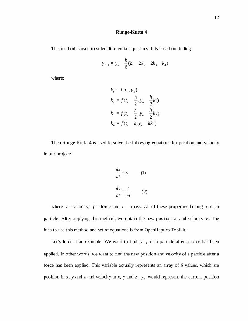
Runge-Kutta 4
This method is used to solve differential equations. It is based on finding
)22(6
43211 kkkkh
yy nn ++++=+
where:
),(
)2
,2
(
)2
,2
(
),(
34
23
12
1
hkyhtfk
kh
yh
tfk
kh
yh
tfk
ytfk
nn
nn
nn
nn
++=
++=
++=
=
Then Runge-Kutta 4 is used to solve the following equations for position and velocity
in our project:
)2(
)1(
m
f
dt
dv
vdt
dx
=
=
where v = velocity, f = force and m = mass. All of these properties belong to each
particle. After applying this method, we obtain the new position x and velocity v . The
idea to use this method and set of equations is from OpenHaptics Toolkit.
Let’s look at an example. We want to find 1+ny of a particle after a force has been
applied. In other words, we want to find the new position and velocity of a particle after a
force has been applied. This variable actually represents an array of 6 values, which are
position in x, y and z and velocity in x, y and z. ny would represent the current position

13
and velocity before the force is applied. We will focus on the position but the same rules
apply to the velocity.
For the position we know:
vdt
dx=
and also that 1+ny depends on 4321 ,,, kkkk . Let’s start with k1 which is simply:
vk =1
For k2 it equals:
122
kh
yk n +=
As mentioned before, ny represents the position x, y and z. h represents the time step
and its value is obtained from the simulation:
01 tth −=
The other two values we need are:
34
232
hkyk
kh
yk
n
n
+=
+=
The we substitute each one of them in:
)22(6
43211 kkkkh
yy nn ++++=+
In this step we know the new positions. However, we need to calculate the velocity
m
f
dt
dv= concurrently –while we obtain the new position-. This is necessary because the
only variables we know are the force f and the mass m which is constant for all
particles. Based on this, we use f and m to obtain v using (2). While this happens, the
14
same v is used to obtain x using (1).
Regarding the velocity, it is obtained using:
m
f
dt
dv=
Lips 3D model
We chose the first model to be a lips image. One part of this project is to show the
final model in the simulation as a reference for the user. That way, he or she will be
aware of the approximate shape of the final model. We will be showing the final model
as a set of points. This set of control points that represent the structure of a lips model
was created in Maya. This software provides human models. Then, the lips were
extracted from one of these models and then exported to an OBJ file. This file includes
the coordinates for the vertices which are later imported into the application.

15
CHAPTER IV
IMPLEMENTATION
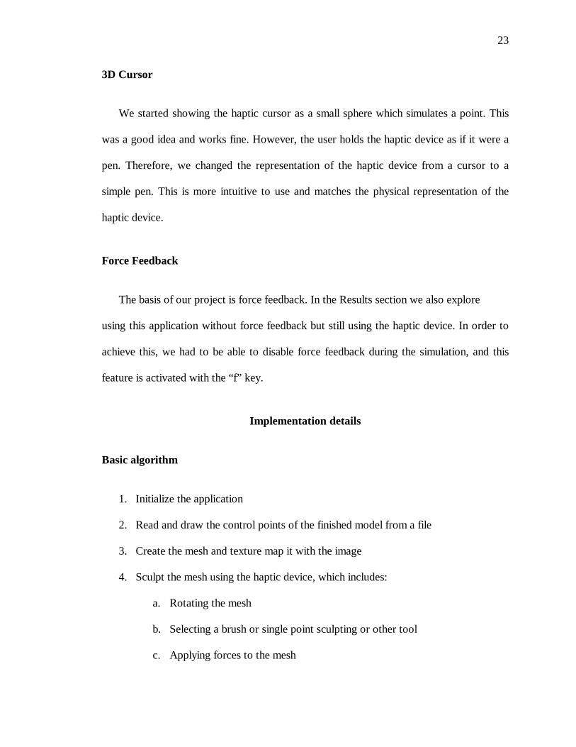
Haptic Device
A haptic device is available in the Graphics Lab in the Computer Science Department.
The model is Phantom Omni Haptic Device.
Figure 3. Haptic Device from Sensable
It allows simulation of forces in 3D. The set of forces that can be obtained are divided
in two according to [Sen05]: forces used to resist motion and forces to assist motion.
When the user touches a 3D object, the haptic device induces forces at a rate of 1000
times a second so that the cursor does not penetrate surfaces. These forces can make
objects feel sticky, soft, viscous, etc.
Forces can be computed in several ways to provide different sensations. In [Sen05]
three main classes of forces are indicated: time dependant, motion dependant or
combination of both. A force that is motion dependant includes spring forces, friction and
16
inertia. Time dependant forces are a function of time, which includes constant forces,
periodic forces and impulses.
The next step is combining the haptic device with graphics. This is because the haptic
device is not used in isolation. It is used to allow the user to interact in a 3D graphics
environment. The first thing to consider is that the refresh rate for the haptic device is
higher than the rate for the graphics loop. A graphics application refreshes the screen 30-
60 times a second. The haptic device has a rate of 1000 times a second to give the user
the sense of touch.
Moreover, events can be triggered while using the haptic device. It could be touching
a mesh or any of the 2 buttons the haptic device provides. For example, a button can be
programmed to grab objects.
The haptic device has a limited workspace. It can move in a space of around 12 in x
12 in x 12 in. This space is enough to move around the virtual environment and it is easy
to get used to this configuration in our project.
HLAPI and OpenGL
This version of the haptic device provides software to interact with it. It is called
OpenHaptics Toolkit Academic Edition v2.0. In fact, it is composed of 2 libraries:
HLAPI (Haptic Library API) and HDAPI (Haptic Device API). In [Sen05] it is explained
that the first one provides low level access to the haptic device. HLAPI provides high
level haptic rendering.
The choice was to use HLAPI. This is because we do not want to worry about
creating force rendering/collision detection algorithms and data structures. Therefore, we
17
can focus on providing an efficient and easy to do sculpting.
HLAPI Basics
Before using the haptic device it is necessary to do a basic setup/initialization.
Moreover, any HLAPI commands need to be contained in hlBeginFrame and
hlEndFrame. Here is where we draw the shapes using the hlBeginShape and hlEndShape.
Each shape has a unique identifier. In fact, any mesh that induces forces needs to be
drawn twice. The first one draws the mesh graphically using OpenGL instructions. The
second one draws the mesh haptically using HLAPI instructions.
Programming Details
This section is divided in three parts: Data structures, Application framework and
Third party software.
Data Structures and Class Design
The NURBS class draws the mesh. The function of the ParticleSystem class is to
track and modify the position of the particles based on the forces applied. Therefore, it is
helped by the HapticForce class to apply forces using the haptic device. The MouseForce
class applies forces using the mouse. This is an extension to compare the difference
between using a force feedback device and the mouse. The idea to use these two last
classes is from OpenHaptics Toolkit. RungeKutta4 computes the new positions and
velocities of the vertices based on the forces applied –also from OpenHaptics Toolkit-.
Finally, the Vertex class represents each individual particle in the particle system.
18
Vertex Class
Each particle has several basic attributes. They are: position and velocity. Moreover,
three extra attributes are added to identify the tool the user is working on, e.g. the brush
tool, extrude tool, etc. We will talk about these tools later in the report.
Particle System Class
This class contains a list of particles based on the Vertex class. It calculates the
position x and velocity v using RungeKutta4. This class also handles rotations of the
mesh.
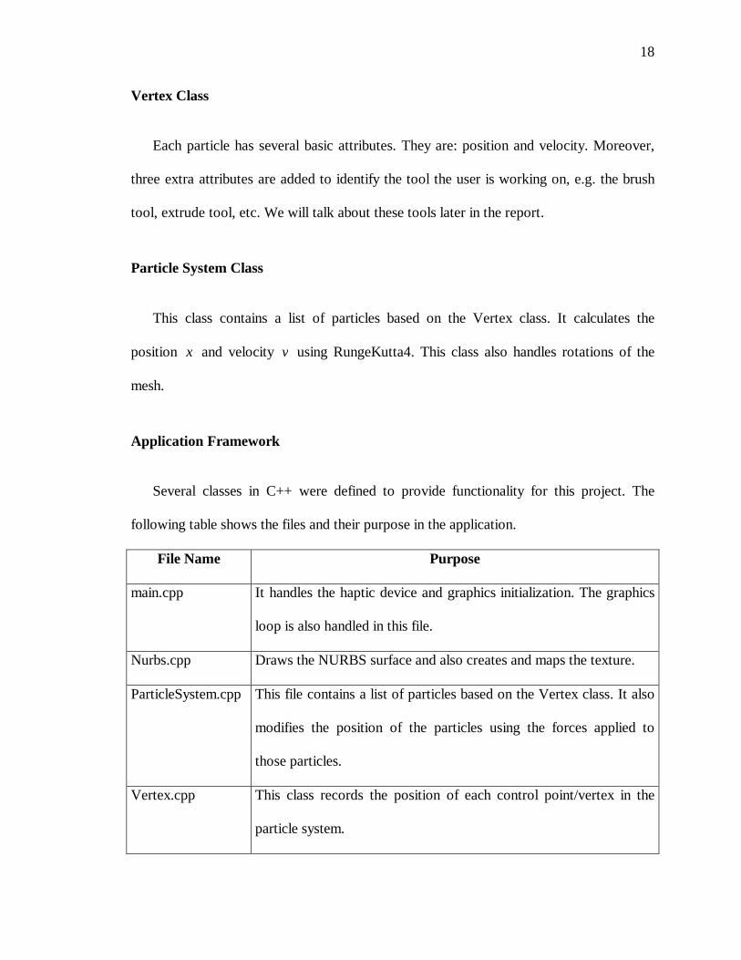
Application Framework
Several classes in C++ were defined to provide functionality for this project. The
following table shows the files and their purpose in the application.
File Name Purpose
main.cpp It handles the haptic device and graphics initialization. The graphics
loop is also handled in this file.
Nurbs.cpp Draws the NURBS surface and also creates and maps the texture.
ParticleSystem.cpp This file contains a list of particles based on the Vertex class. It also
modifies the position of the particles using the forces applied to
those particles.
Vertex.cpp This class records the position of each control point/vertex in the
particle system.
19
The application developed provides basic error checking. Moreover, some
optimization is provided but it is not extensive. As we have mentioned, some useful
features like brush and rotations are provided, still, many other editing functions are not
supported. If necessary, new features can be added to the code, for example, the
possibility of adding new control points to the mesh. For this project, the number of
control points is set and can not be modified on-the-fly. Changing the code to support
more control points is not difficult.
The smoothing algorithm is based on NURBS surfaces, which are implemented in
OpenGL. Texture mapping is done by simple interpolation techniques. Regarding the
data structure that creates the image and the 3D model, it does not need to be modified if
we want to model a different object. We should, however, use a default file name and
format to achieve this. For the image, it should be a bmp 512x512 pixels file. The file
format for the 3D model should be an obj file.
Third party software
As mentioned before, Maya was used to obtain the model for the lips. This software
is also available in the Graphics Lab. The version is 7.0.1.
Features of the implementation
Brush
This enhancement is about the capability to induce force on more than one control
point at a time. This option allows the user to speed up modeling. When using this
functionality, the applied force is not evenly distributed but equally applied to each point.
20
This is because if we split the applied force the resulting force in each point will be so
small that it will not move.
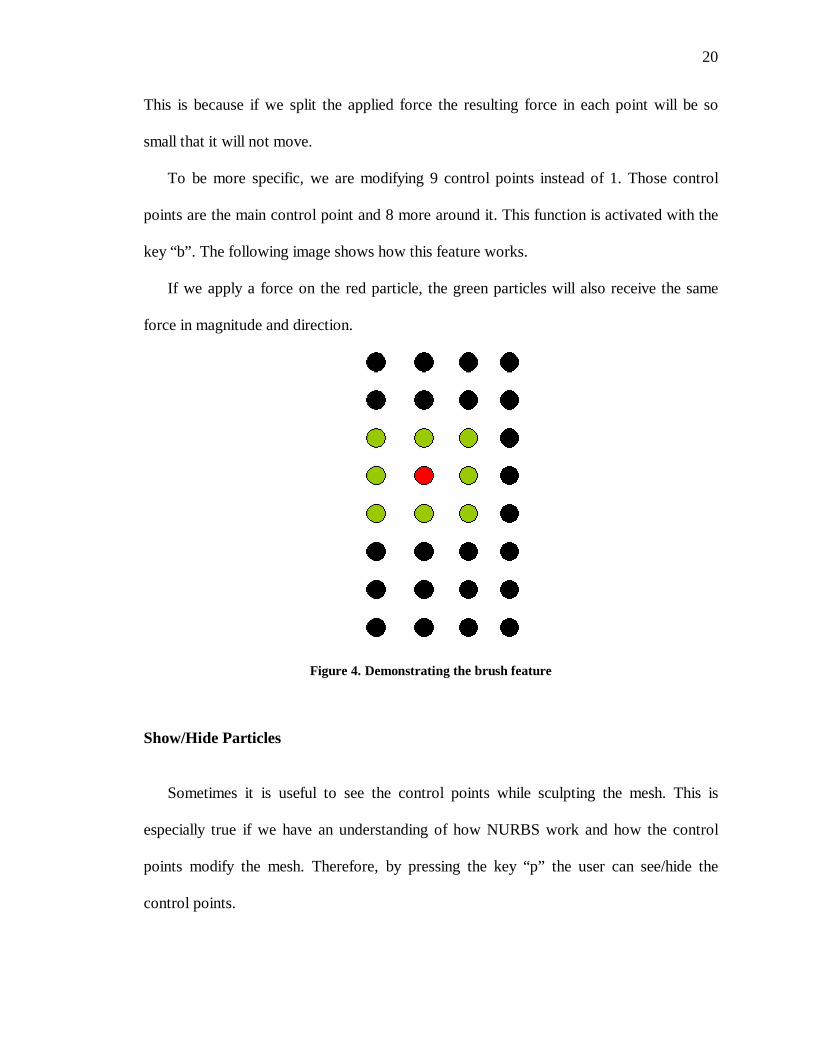
To be more specific, we are modifying 9 control points instead of 1. Those control
points are the main control point and 8 more around it. This function is activated with the
key “b”. The following image shows how this feature works.
If we apply a force on the red particle, the green particles will also receive the same
force in magnitude and direction.
Figure 4. Demonstrating the brush feature
Show/Hide Particles
Sometimes it is useful to see the control points while sculpting the mesh. This is
especially true if we have an understanding of how NURBS work and how the control
points modify the mesh. Therefore, by pressing the key “p” the user can see/hide the
control points.
21
Rotations
Rotations are controlled using the keypad and the PageUp and PageDown keys.
The Left and Right keys control the rotations around the Y axis. The Up and Down keys
control the rotations around the X axis. Rotations around the Z axis are controlled using
the PageUp and PageDown keys.
Extrude
When we are modeling, it should be possible to extract (in or out/push or pull) the
mesh. We had two options here:
a) we can enable touching the mesh in the front and in the back.
b) we can enable touching the mesh only in the front and switch between push and
pull using a key
We selected the second option but we are not using a key. First of all, the haptic
device has a stylus in the extremity of the mechanical arm, which has a button. In our
project this button is programmed to control the extrude feature. When the simulation
starts, the default mode is push. It means that when we induce a force in the mesh the
result is that we push the mesh. Then, we can press the button to activate the pull mode.
In this mode, when we induce a force in the mesh it moves towards us, in other words,
we pull the mesh. We can switch between modes at any time and there are no constraints
to do this.
22
3D Lips Model
It is also possible to see the final model as a reference. Viewing and hiding the model
is activated using the “m” key. We found that hiding the model is sometimes useful since
it obstructs the view of the image. At the same time, this final model will be useful when
we are not sure about the 3D shape of the mesh.
3D Paint
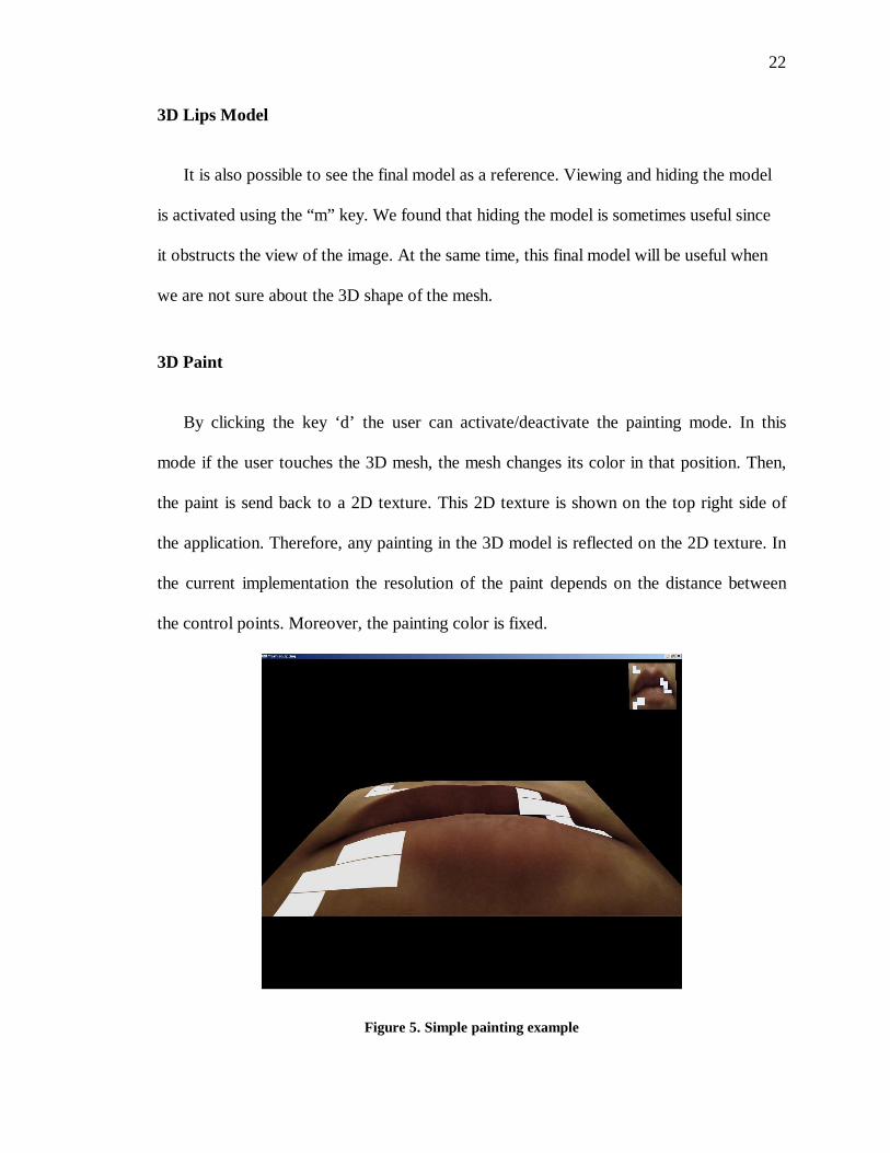
By clicking the key ‘d’ the user can activate/deactivate the painting mode. In this
mode if the user touches the 3D mesh, the mesh changes its color in that position. Then,
the paint is send back to a 2D texture. This 2D texture is shown on the top right side of
the application. Therefore, any painting in the 3D model is reflected on the 2D texture. In
the current implementation the resolution of the paint depends on the distance between
the control points. Moreover, the painting color is fixed.
Figure 5. Simple painting example
23
3D Cursor
We started showing the haptic cursor as a small sphere which simulates a point. This
was a good idea and works fine. However, the user holds the haptic device as if it were a
pen. Therefore, we changed the representation of the haptic device from a cursor to a
simple pen. This is more intuitive to use and matches the physical representation of the
haptic device.
Force Feedback
The basis of our project is force feedback. In the Results section we also explore
using this application without force feedback but still using the haptic device. In order to
achieve this, we had to be able to disable force feedback during the simulation, and this
feature is activated with the “f” key.
Implementation details
Basic algorithm
1. Initialize the application
2. Read and draw the control points of the finished model from a file
3. Create the mesh and texture map it with the image
4. Sculpt the mesh using the haptic device, which includes:
a. Rotating the mesh
b. Selecting a brush or single point sculpting or other tool
c. Applying forces to the mesh
24
5. The new position for the control point is calculated and the mesh is drawn again.
6. Repeat step 4 until the control points have been moved to their desired locations
Major issues
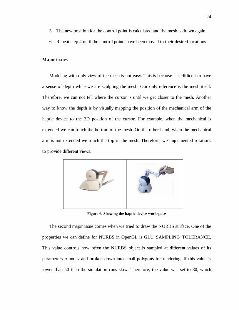
Modeling with only view of the mesh is not easy. This is because it is difficult to have
a sense of depth while we are sculpting the mesh. Our only reference is the mesh itself.
Therefore, we can not tell where the cursor is until we get closer to the mesh. Another
way to know the depth is by visually mapping the position of the mechanical arm of the
haptic device to the 3D position of the cursor. For example, when the mechanical is
extended we can touch the bottom of the mesh. On the other hand, when the mechanical
arm is not extended we touch the top of the mesh. Therefore, we implemented rotations
to provide different views.
Figure 6. Showing the haptic device workspace
The second major issue comes when we tried to draw the NURBS surface. One of the
properties we can define for NURBS in OpenGL is GLU_SAMPLING_TOLERANCE.
This value controls how often the NURBS object is sampled at different values of its
parameters u and v and broken down into small polygons for rendering. If this value is
lower than 50 then the simulation runs slow. Therefore, the value was set to 80, which

25
does not decrease the quality of the mesh and does not consume all the processor time at
the same time.
The third major issue appeared after implementing rotations. Sometimes, when we
rotated the mesh, it accidentally touched or hit the 3D cursor. This, in turn, creates a force
that is applied to the haptic device and felt by the person holding the feedback device.
Sometimes it can cause the haptic device to kick. A kick is a sudden and violent force in
the haptic device. This is because force feedback works in two ways: the user can apply
forces in the mesh but also feels the forces on the haptic device. This issue was solved by
disabling haptic interactions until the rotation was completed. In other words, no forces
are rendered while the particles are updating its position during a rotation. This happens
during a really small amount of time so that the user is not aware of this. This
workaround does not disrupt the modeling job since a user will not intend to modify the
shape of a mesh until the rotation has finished.
26
CHAPTER V
RESULTS
Comparing the Haptic Device and the Mouse
The simulation has the possibility of using the mouse to move the control points
around. The purpose is to compare results when using the haptic device and the mouse.
The function of the mouse is to move the control points to new positions. Forces are
still induced on the points but there is no feedback on the amount of force applied.
One important difference between the two approaches is that when using the mouse
we can not move the points on the mesh continuously. In other words, we need to modify
each control point in a discrete way (one at a time but can move continuously if
implemented). Furthermore, with the haptic device the mesh moves while the user is
touching it, therefore the user “sees” when the desired shape is met and he or she can stop
touching the mesh.
When using the mouse, we need to move 12x12 control points (144 control points
which is the size of the mesh in our implementation). Moving each control point
individually is difficult since a control point actually affects more than one curve
segment. Therefore, after doing a test, we found that it can take up to 4-5 times longer to
finish the model with the mouse.
Moreover, if the control points are hidden it is difficult to pick them since the mouse
27
works in 2D. When using the haptic device we do not need to worry about the control
points, we just need to touch the mesh and sculpt it.
Mapping Haptic Device to Graphics Simulation
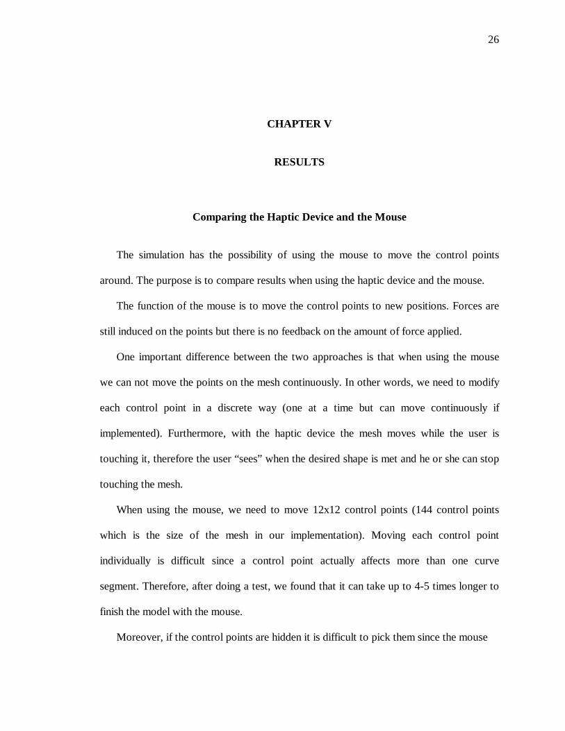
As different coordinate systems are being used, the haptic device works on physical
coordinates and those need to be mapped to the coordinate space used by the graphic
simulation. However, this is done using HLAPI. The pipeline is:
Figure 7. OpenGL has different coordinate systems
NURBS in OpenGL
OpenGL provides an efficient way to draw NURBS surfaces. We are also using
OpenGL to texture map the image to the NURBS surface. We can control several
parameters like the knot values and the resolution of the mesh. A high resolution makes
the simulation slower. That is why a small resolution was chosen, and to the human eye
the mesh still looks smooth.
28
We came across a problem when drawing the NURBS surface. The first attempt
successfully generated a mesh with 8 control points. However, a mesh with more than 8
control points could not be drawn. After looking into this, we realized that we need to
disable the hardware acceleration in the graphics card. This is a simple process achieved
using Windows settings. However, we found little documentation about this. After we
disabled hardware acceleration we were able to successfully generate NURBS surfaces
with more than 8 control points.
Regarding the number of control points, we started using a mesh of 20x20 control
points. We were able to achieve good results but the time to generate a model was
excessive. This was because of two reasons:
a) the number of control points to modify is high –400 control points-
b) the number of operations to compute the position of all points is too high
Then, we reduced the number of control points to 12x12. There is almost no
difference in the final model and the number of points decreased to less than half. The
result is a simulation where any delay is not noticeable.
Features of the implementation
We also provide different features like a brush and rotations. Most of the functions
are activated using the keyboard; however, the Extrude mode is not. Using the stylus
button to switch between modes is very intuitive and easy to use. Moreover, the user does
not have to stop modeling to activate the extrude mode. The painting feature provides
raw capabilities but can be extended and improved.
29
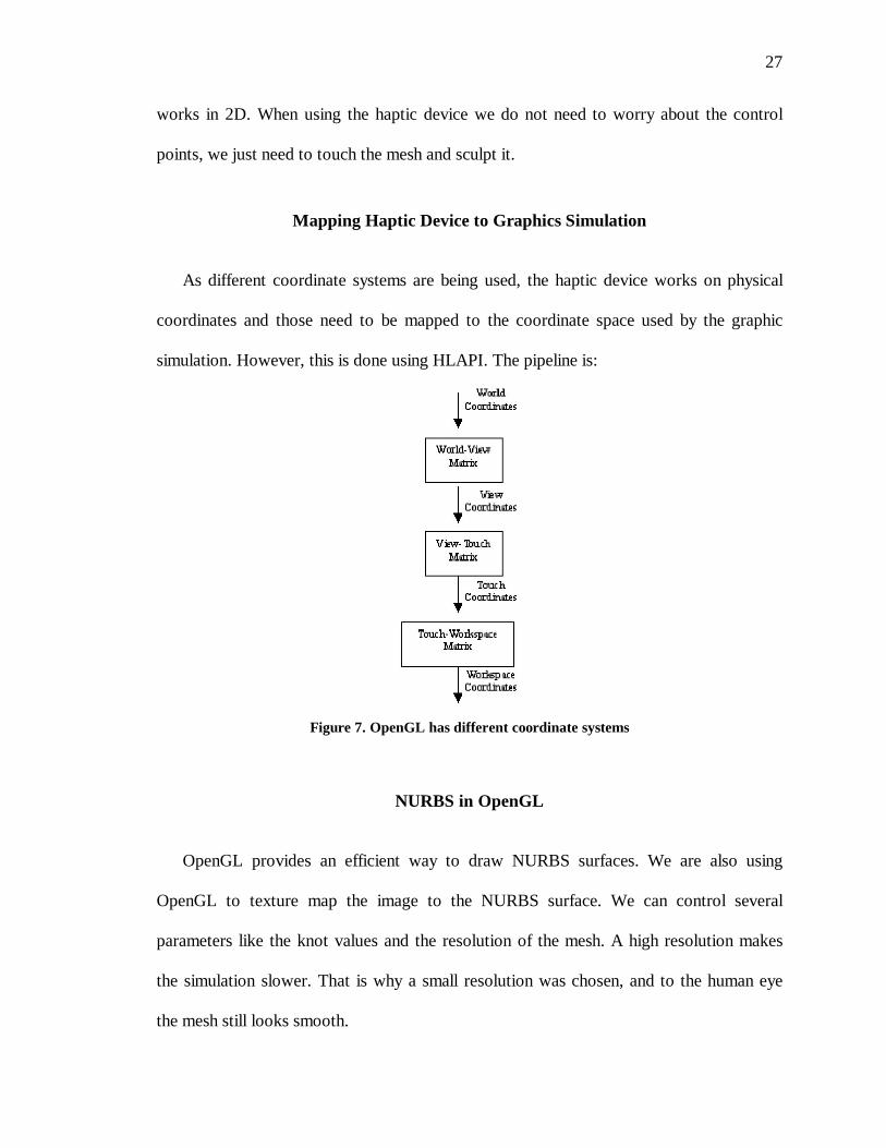
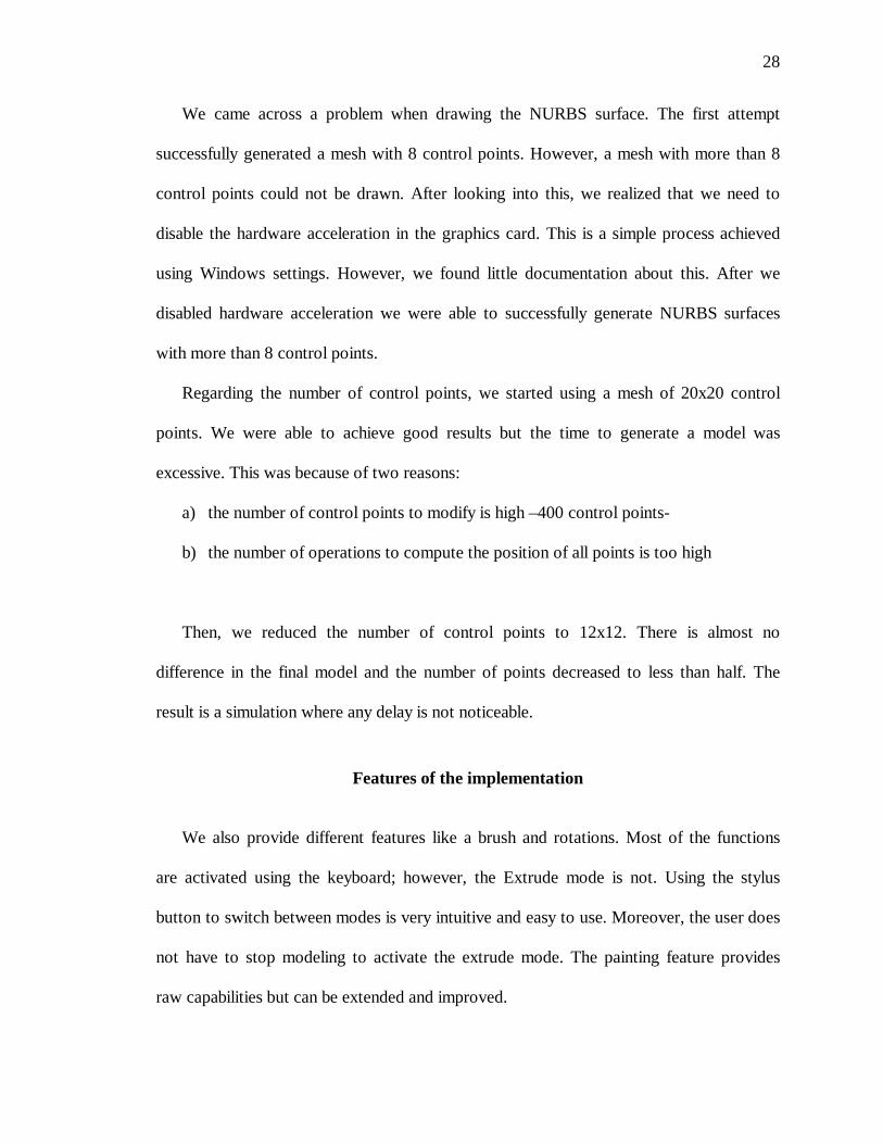
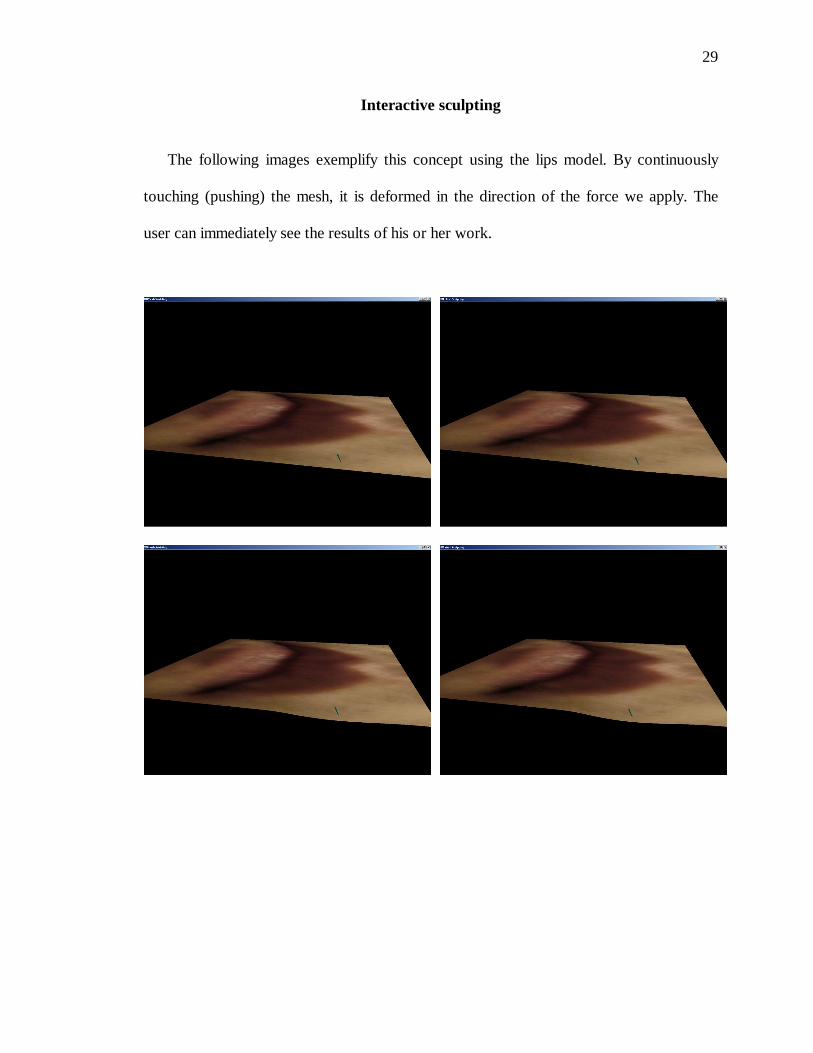
Interactive sculpting
The following images exemplify this concept using the lips model. By continuously
touching (pushing) the mesh, it is deformed in the direction of the force we apply. The
user can immediately see the results of his or her work.
30

31
Figure 8. Generation of a deformation step by step
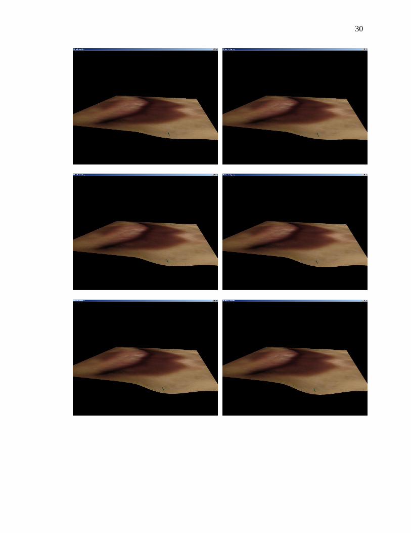
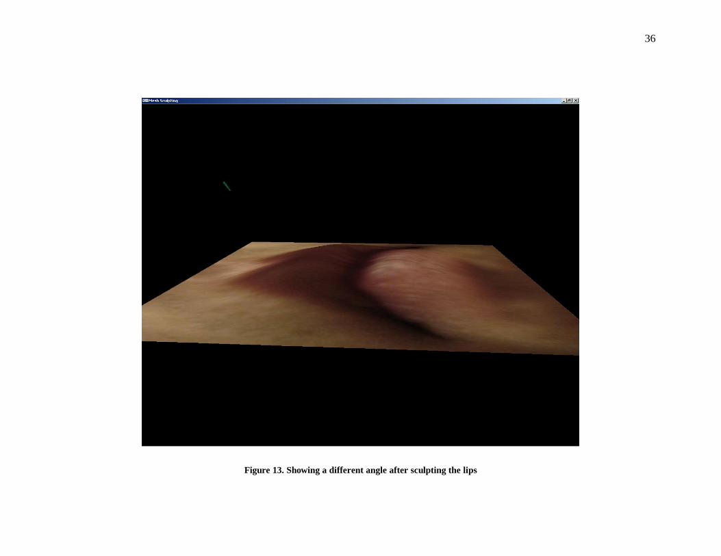
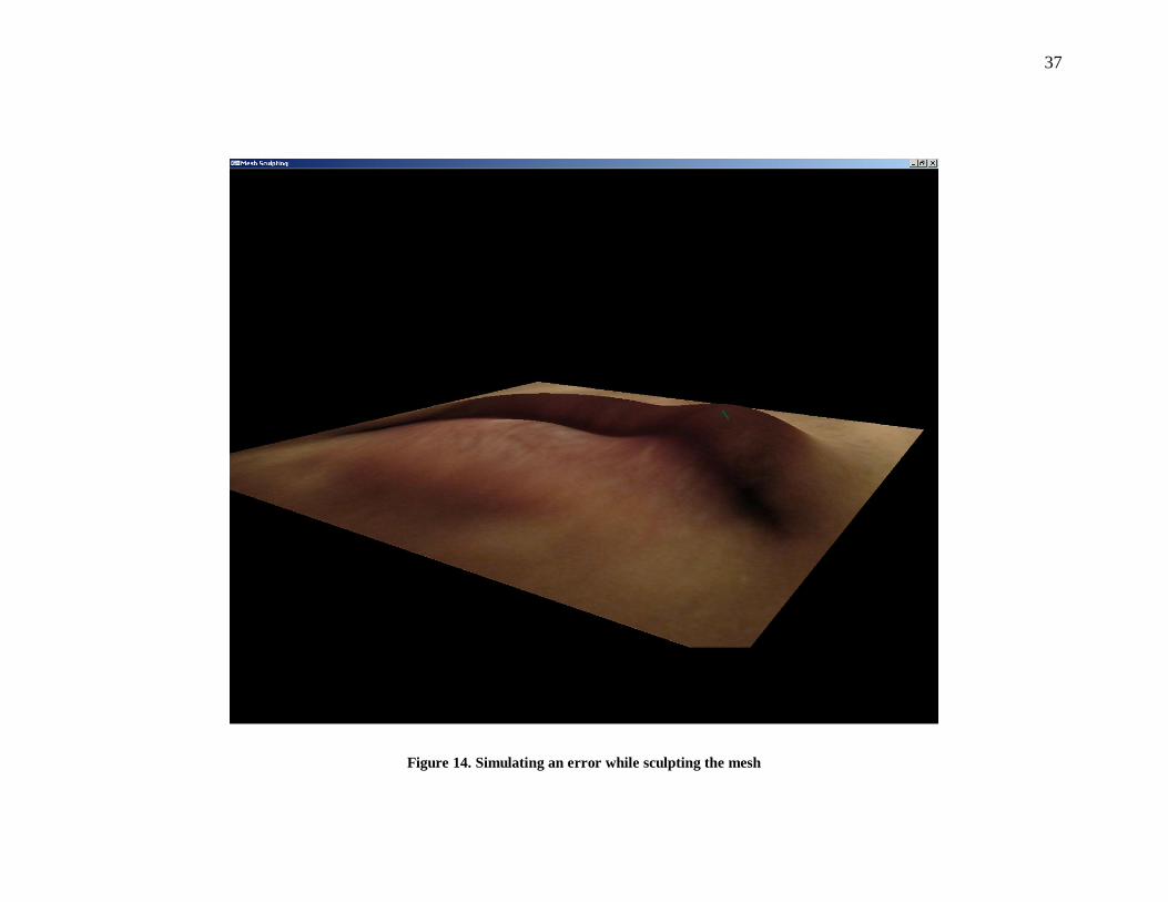
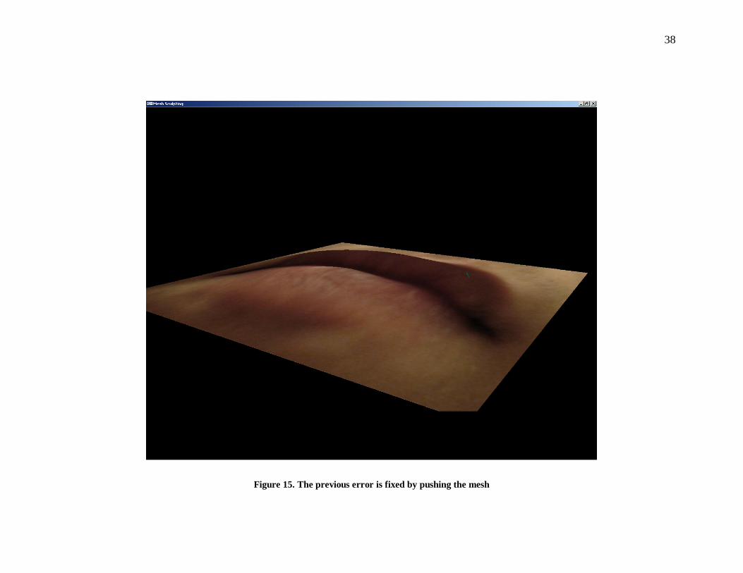
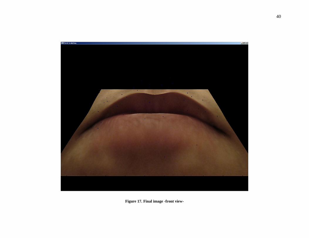
Lips sculpting
The next images show intermediate steps before achieving the final deformation. We
start with a flat mesh. We deformed the lower lip and then the upper lip. Screenshots
from different angles are presented. While we were working on the deformations, we had
to rotate the mesh several times to make sure the deformations were correct.
In one of them, we simulated a deformation where we pulled too much. In order to fix
this, we had to push the image back to its original position.
Finally, we show how the final mesh looks like. It took us around 4 minutes to
complete the deformations.

32
Figure 9. Initial flat image as a mesh
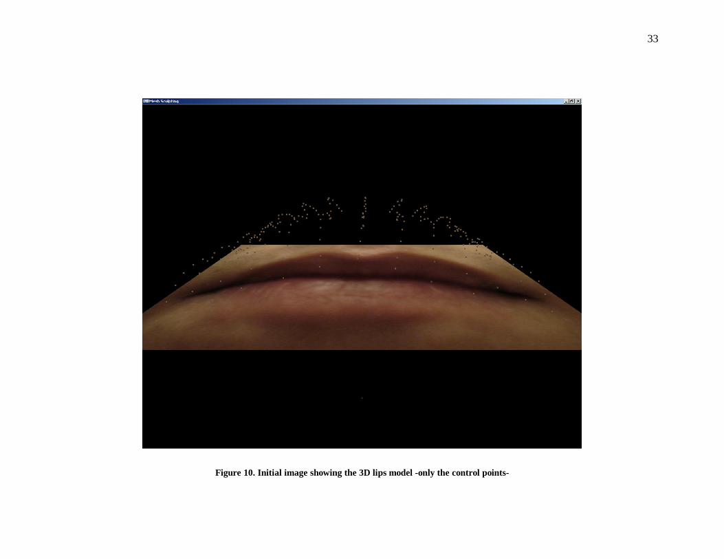
33
Figure 10. Initial image showing the 3D lips model -only the control points-
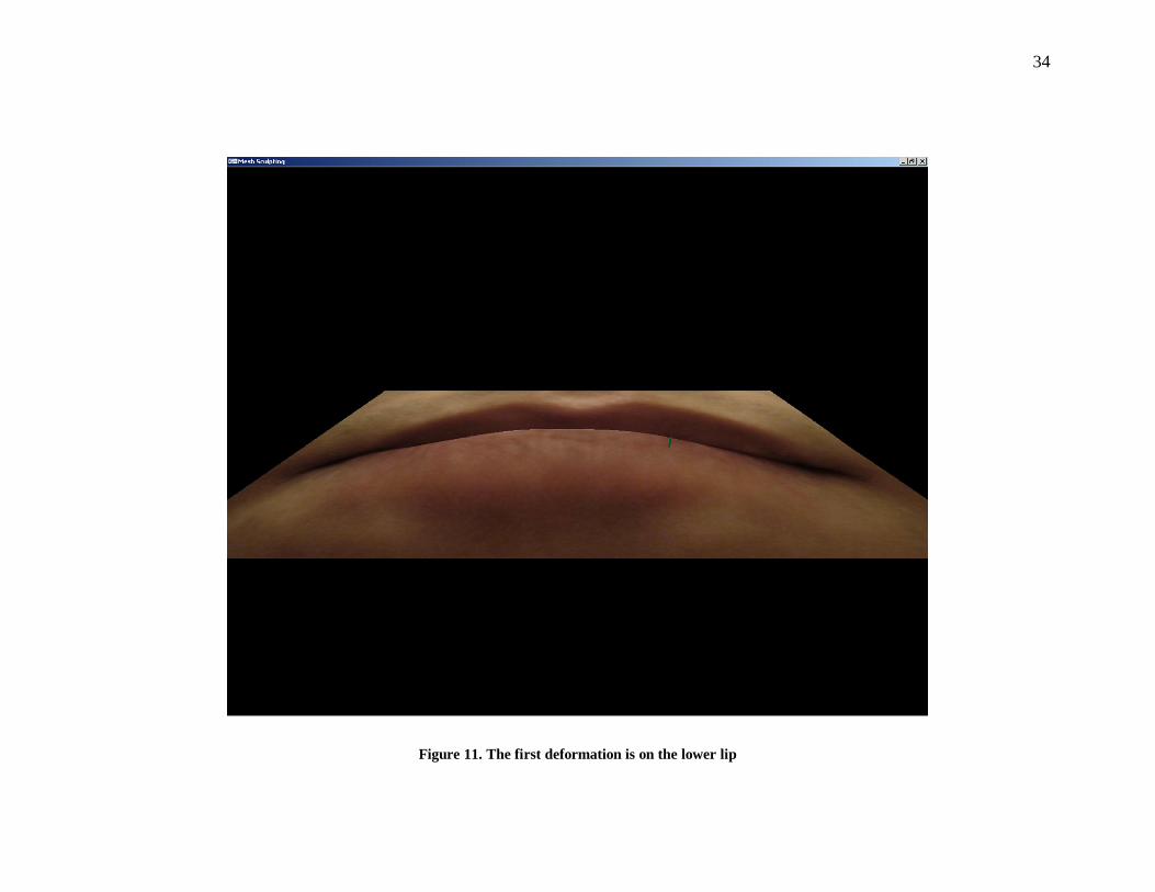
34
Figure 11. The first deformation is on the lower lip
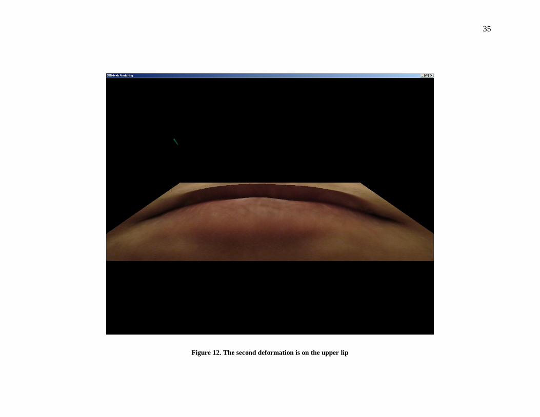
35
Figure 12. The second deformation is on the upper lip
36
Figure 13. Showing a different angle after sculpting the lips
37
Figure 14. Simulating an error while sculpting the mesh
38
Figure 15. The previous error is fixed by pushing the mesh

39
Figure 16. Final image showing the control points-side view-
40
Figure 17. Final image -front view-
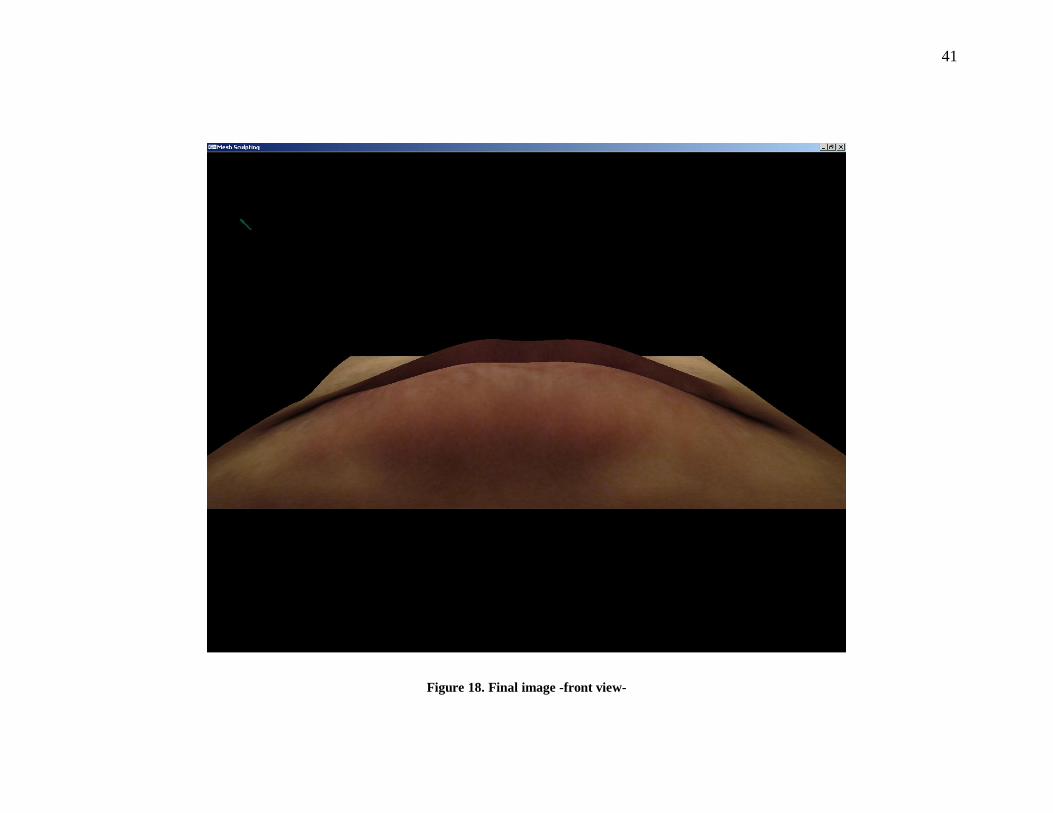
41
Figure 18. Final image -front view-
42
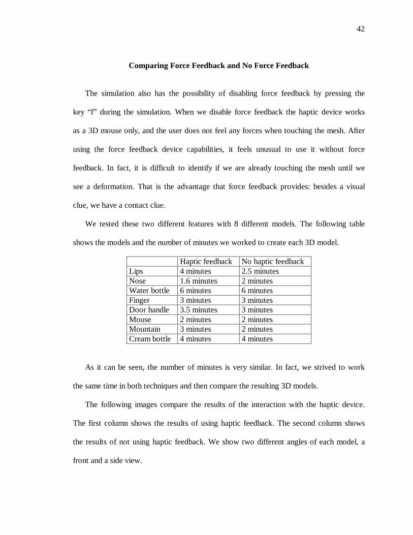
Comparing Force Feedback and No Force Feedback
The simulation also has the possibility of disabling force feedback by pressing the
key “f” during the simulation. When we disable force feedback the haptic device works
as a 3D mouse only, and the user does not feel any forces when touching the mesh. After
using the force feedback device capabilities, it feels unusual to use it without force
feedback. In fact, it is difficult to identify if we are already touching the mesh until we
see a deformation. That is the advantage that force feedback provides: besides a visual
clue, we have a contact clue.
We tested these two different features with 8 different models. The following table
shows the models and the number of minutes we worked to create each 3D model.
Haptic feedback No haptic feedback Lips 4 minutes 2.5 minutes Nose 1.6 minutes 2 minutes Water bottle 6 minutes 6 minutes Finger 3 minutes 3 minutes Door handle 3.5 minutes 3 minutes Mouse 2 minutes 2 minutes Mountain 3 minutes 2 minutes Cream bottle 4 minutes 4 minutes
As it can be seen, the number of minutes is very similar. In fact, we strived to work
the same time in both techniques and then compare the resulting 3D models.
The following images compare the results of the interaction with the haptic device.
The first column shows the results of using haptic feedback. The second column shows
the results of not using haptic feedback. We show two different angles of each model, a
front and a side view.
43
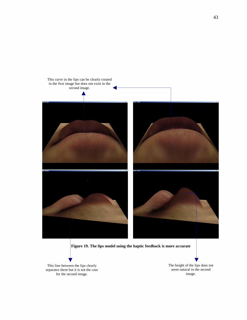
Figure 19. The lips model using the haptic feedback is more accurate
This curve in the lips can be clearly created in the first image but does not exist in the
second image.
The height of the lips does not seem natural in the second
image.
This line between the lips clearly separates them but it is not the case
for the second image.
44
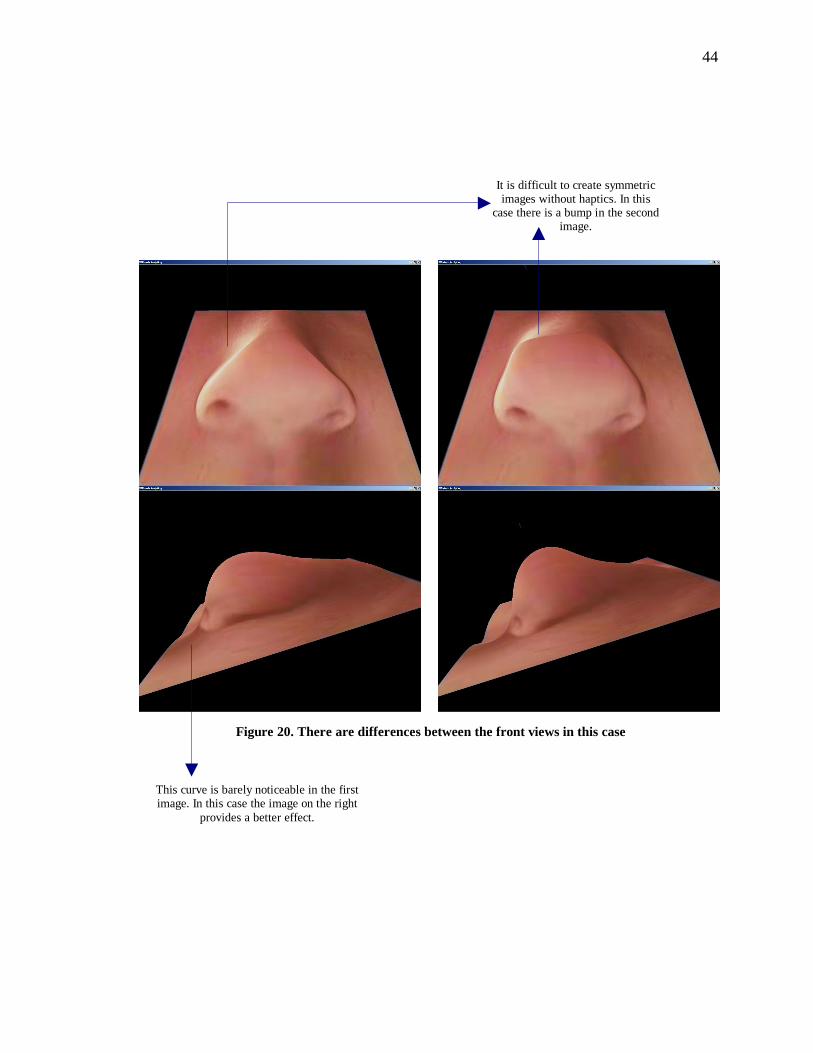
Figure 20. There are differences between the front views in this case
It is difficult to create symmetric images without haptics. In this
case there is a bump in the second image.
This curve is barely noticeable in the first image. In this case the image on the right
provides a better effect.
45
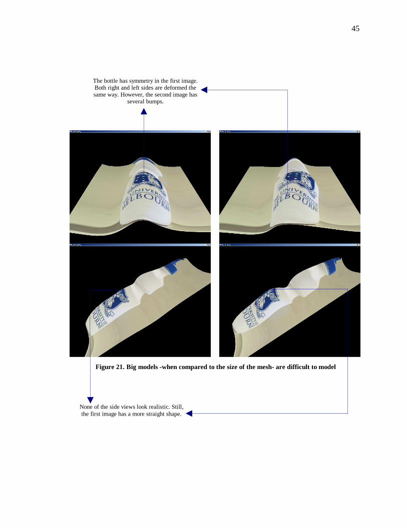
Figure 21. Big models -when compared to the size of the mesh- are difficult to model
The bottle has symmetry in the first image. Both right and left sides are deformed the same way. However, the second image has
several bumps.
None of the side views look realistic. Still, the first image has a more straight shape.
46
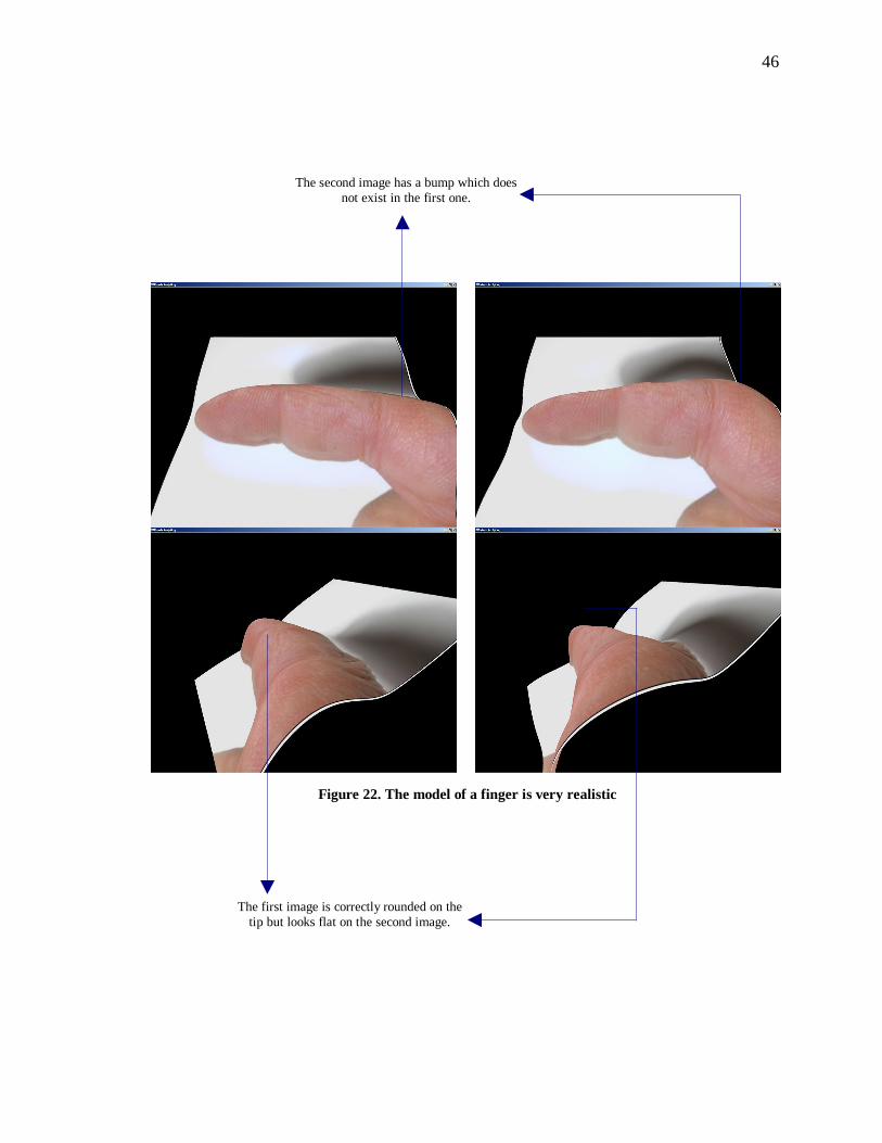
Figure 22. The model of a finger is very realistic
The second image has a bump which does not exist in the first one.
The first image is correctly rounded on the tip but looks flat on the second image.
47
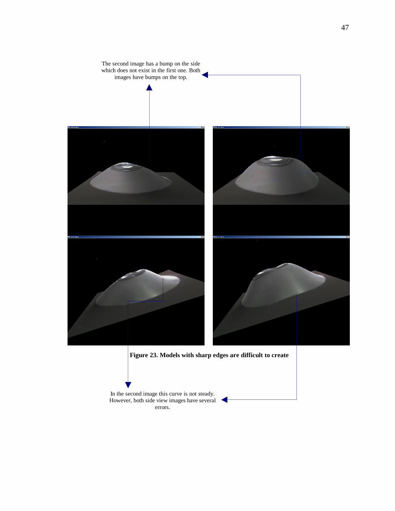
Figure 23. Models with sharp edges are difficult to create
The second image has a bump on the side which does not exist in the first one. Both
images have bumps on the top.
In the second image this curve is not steady. However, both side view images have several
errors.
48
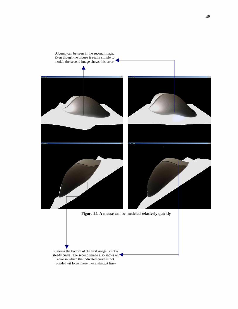
Figure 24. A mouse can be modeled relatively quickly
A bump can be seen in the second image. Even though the mouse is really simple to model, the second image shows this error.
It seems the bottom of the first image is not a steady curve. The second image also shows an
error in which the indicated curve is not rounded –it looks more like a straight line-.
49
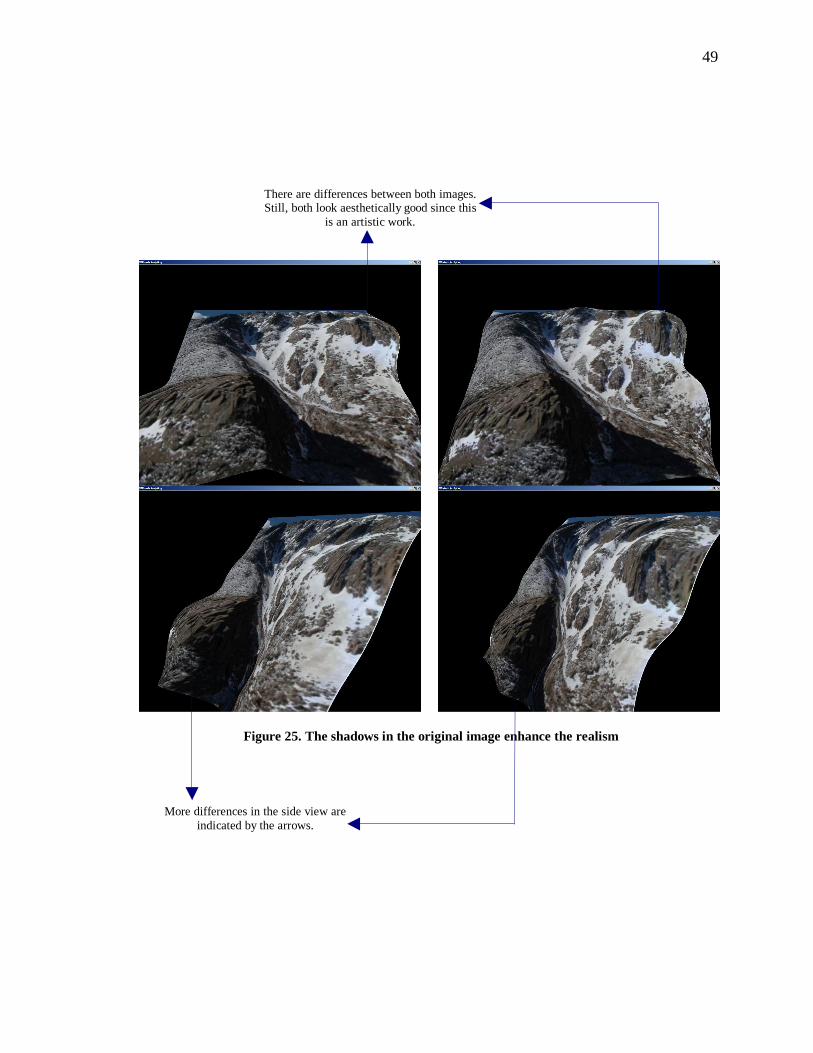
Figure 25. The shadows in the original image enhance the realism
There are differences between both images. Still, both look aesthetically good since this
is an artistic work.
More differences in the side view are indicated by the arrows.
50
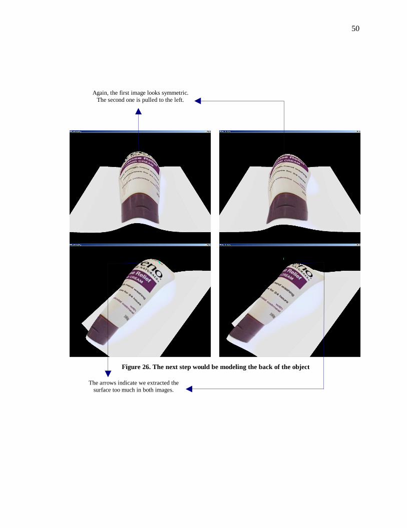
Figure 26. The next step would be modeling the back of the object
Again, the first image looks symmetric. The second one is pulled to the left.
The arrows indicate we extracted the surface too much in both images.
51
The images seem similar; however, the aesthetic quality of the image and 3D model
are better when using haptic interaction. When we do not use the haptic device we loose
some control when sculpting the mesh, that is why some curves are not steady. We either
push too much or pull too much, causing wrong deformations and the need to fix them.
Therefore, we can achieve the same results without force feedback, but the difference is
that it will take longer. This is because in our tests we worked approximately the same
length of time on both models, then we need to put more time to fix the wrong
deformations caused when we do not use haptic feedback. Finally, when using force
feedback we can effectively coordinate the force applied to achieve the deformation we
want because of the feedback we receive.
52
CHAPTER VI
CONCLUSION
When comparing the results of using the haptic device and the mouse, it is obvious
that haptic interaction provides an easier to use and faster way to sculpt a mesh. The same
happens when we compare the results of not using force feedback. Using force feedback
is intuitive; and when we disabled force feedback the experience and results are
diminished. Moreover, in order to sculpt a mesh and have perfect control of it, many tools
need to be implemented. In this project we implemented a few of them.
The method used removes the need to directly modify the control points in a mesh.
Instead, we focus on modifying the mesh itself by touching it. The ability of the haptic
device to work in 3D is a big advantage over the mouse, which works on a 2D
environment. Still, it requires some practice to perceive the cursor’s Z location in the
graphics simulation when no depth cues are provided.
Most importantly, this method provides a real time interaction when the mesh is
sculpted. After sculpting the mesh –which results from applying a force in a control
point- we can immediately see the results as a new sculpted image.
NURBS provided flexibility and their properties were important when drawing the
mesh. The NURBS implementation of OpenGL was even more helpful. We were able to
focus on other parts of the project by using it.
The painting feature is an interesting extension of this project. The user, besides
53
modeling, can apply colors to the texture in 3 dimensions. In fact, we could implement a
function to save the modified 2D texture to a file so that it can be used more than one
time.
Finally, force feedback is an important component towards realism when modeling.
Our sense of touch gives us feedback when touching a physical object, and the haptic
device provides us with feedback when touching a virtual object.

54
CHAPTER VII
FUTURE WORK
This project showed a basic framework to sculpt an image using the haptic device.
Still, several extensions can be included in future versions.
Editing Tools
New tools to manipulate the mesh can be added. For example, an Undo/Redo
command could be useful if an editing operation did not work well: we could easily
retrieve a previous version of the mesh. We could also create a selection tool where only
a set of vertices are affected with the haptic device.
NURBS limitations
Surfaces better than NURBS will be needed if we want to model hands, cups, bottles,
etc. This is because these objects are not continuous. Available surfaces that can achieve
this include S-patches.
Different Views
It could also be useful to provide different views of the mesh concurrently. This
would require the creation of windows to contain each view. Rotating the mesh to
visualize it from different angles helps but we could also provide a fixed top/side view to
55
the user.
Haptic Workspace
We are limited to the haptic device workspace. Therefore, it only works on a defined
volume. For this project the deformable mesh is contained within this volume, but other
simulations may not work this way, which represents a disadvantage. A possible solution
could be translations. In other words, provide the user with the ability to move the
graphic simulation so that the volume he or she is interested in is contained within the
working volume of the haptic device.
3D paint
This feature can be improved. For example, the resolution of the paint in the current
implementation depends on the distance between the particles in the mesh. A better
option would be to apply the paint to each individual pixel in the texture. Moreover, the
painting color is fixed, but we could add a color palette in future versions.
Adding knots on the fly
Creating a smoother or rougher mesh means adding or removing knots. In this
implementation the knot and control points arrays are fixed, therefore this capability is
not implemented. In fact, adding or removing knots implies adding and removing control
points too. To add this capability we would need to create variable size arrays and include
functionality to overwrite the arrays.
56
Integration with image editing software
This application could also be used in image editing software. The images that we
usually see in advertisement or web pages can be enhanced by adding more realism. Our
application can do this, the result would be an image that provides 3D cues by showing
different depths in the image. In order to do this, we would need a way to automatically
resize the mesh depending on the size of the image –because in the current version the
image resolution is fixed-. Then, after sculpting it, we would need to be able to export the
new image to a file.
This way, the sculpted images could help attract user attention to the advertisement or
web page. Since we quickly decide what web pages are useful to us and which ones are
not, showing information –in this case images- in a different way could give the user a
reason to keep his or her attention on the web page.
Image recognition
When we touch the mesh, sometimes we touch the incorrect control points. This
causes wrong deformations and then we need to fix them. For example, while deforming
the lips we can accidentally touch the skin since the haptic device can touch anywhere
inside the image.
Although it is not the focus of this project, we could use image recognition
techniques. These techniques can identify boundaries in the original 2D image and apply
certain rules to those boundaries. Using the lips example, image recognition would
identify the boundaries of the lips and the line between them. Then, we can define our
own rules and apply them to the control points closer to those boundaries. One of those
57
rules could fix the position of those control points while we sculpt the mesh. Therefore,
sculpting the lip would and the mesh inside it including control points near the boundary
would not affect the skin. Another rule could set those control points as a “selection”.
These “selected” control points would behave the same way when we induce a force in
one of them. In this case, it would be for the control points to have the same height by
just touching one of them.
Image module limitations
Our application only loads images of equal size and width, therefore, the module that
loads the 2D image can be improved to read any image size. In fact, we could also
include a module to save the 3D image to an image file. This new file could be a 2D or
3D representation of the 3D mesh. If it is a 2D representation it usually looks similar to
the original image. In this case we could include depth cues like shadows or other objects
so that it gives the user a three dimensional perspective. A side view of the image may
also provide depth cues because the different heights will hide some parts of the image.
58
CHAPTER VIII
BIBLIOGRAPHY
[AGGZ03] Adaptive techniques for real-time haptic and visual simulation of bone
dissection. M. Agus, A. Giachetti, E. Gobbetti, G. Zanetti and A. Zorcolo.
Proceedings of the IEEE Virtual Reality Conference. 2003.
[CA06] Interactive shape editing: towards virtual clay. M. Cani and A. Angelidis.
SIGGRAPH 2006.
[FOL02] ArtNova: Touch-enabled 3D model design. M. Foskey, M. A. Otaudy and
M. C. Lin. Proceedings of the IEEE Virtual Reality Conference. 2002.
[IYUM04] Food simulator: a haptic interface for biting. H. Iwata, H. Yano, T.
Uemura and T. Moriya. Proceedings of the IEEE Virtual Reality
Conference. 2004.
[JTKN99] Painting textures with a haptic interface. D. Johnson, T. Thompson, M.
Kaplan, D. Nelson and E. Cohen. IEEE Virtual Reality Conference
Proceedings. 1999.
[LF03] A painting interface for interactive surface deformations. J. Lawrence, T.
Funkhouser. Proceedings of the 11th Pacific Conference on Computer
Graphics and Applications. IEEE 2003.
59
[MQW01] Virtual clay: a real time sculpting system with haptic toolkits. K
McDonnell, H. Qin and R. Wlodarczyk. Proceedings of the 2001
Symposium on Interactive 3D Graphics. ACM 2001.
[ORC06] A six degree of freedom god object method for haptic display of rigid
bodies. M. Ortega, S. Redon and S. Coquillar. Proceedings of the IEEE
Virtual Reality Conference. 2006.
[PNCD01] Effects on viewing and orientation on path following in a medical
teleoperation environment. P.J. Passmore, C. F. Nielsen, W. J. Cosh and
A. Darzi. Proceedings of the IEEE Virtual Reality Conference. 2001.
[SEJL04] Pre-surgical cranial implant design using the PARIS prototype. C.
Scharver, R. Evenhouse, A. Johnson and J. Leigh. Proceedings of the
IEEE Virtual Reality Conference. 2004.
[Sen05] Sensible technologies. Open Haptics Toolkit v2.0. Programmer’s guide.
[SP86] Free-form deformation of solid geometric models. T. Sederberg and S.
Parry. SIGGRAPH 1986.
[SP97] Haptic display of visual images. Y. Shi and D. Pai. IEEE Virtual Reality
Annual International Symposium Proceedings. 1997.
[FDFH97] Computer graphics: principles and practice. Foley, van Dam, Feiner,
Hughes. Addison Wesley 1997.
60
APPENDIX A
CONFIGURATION/INSTALLATION
Installation requirements
The following software is required to run the application:
• Microsoft Visual Studio 2005
• Phantom Haptic Device
• OpenHaptics Academic Edition v2.0. The libraries it provides are compiled
for Microsoft Visual C++ 6.0. Therefore, they need to be compiled using
Microsoft Visual Studio 2005 using the instructions provided in the
OpenHaptics software. This software is usually included with the haptic
device. If not, this software is included with the source files of the application
too.
• OpenGL, GLUT and GLAUX libraries which are included in MS VS2005
installation.
Compilation procedures
This application is written in C++. It contains 8 header files and 7 cpp files.
Everything is put together using a solution file. This file is open using Visual Studio 2005
since the software is written to run in this IDE. The steps to compile the software are:
• Double click the .sln file to open in Visual Studio 2005
61
• In VS 2005 click on the “Build” menu and then “Rebuild Solution”
• You can run the application from this software by clicking on “Debug” menu
and then “Start”
Running the software
This application contains both the source files and executable files. If you want to run
the application then open the folder “Binaries” and double click the file MS.exe. This
opens the application. The images are located in the “Data” folder which is where the
application looks for the image files. The default image read by the application should be
named img.bmp
62
APPENDIX B
USER GUIDE/DEMO
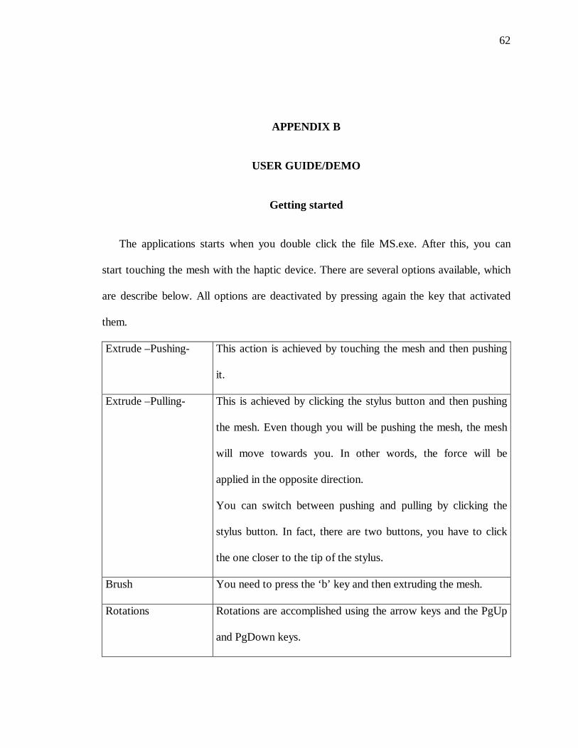
Getting started
The applications starts when you double click the file MS.exe. After this, you can
start touching the mesh with the haptic device. There are several options available, which
are describe below. All options are deactivated by pressing again the key that activated
them.
Extrude –Pushing- This action is achieved by touching the mesh and then pushing
it.
Extrude –Pulling- This is achieved by clicking the stylus button and then pushing
the mesh. Even though you will be pushing the mesh, the mesh
will move towards you. In other words, the force will be
applied in the opposite direction.
You can switch between pushing and pulling by clicking the
stylus button. In fact, there are two buttons, you have to click
the one closer to the tip of the stylus.
Brush You need to press the ‘b’ key and then extruding the mesh.
Rotations Rotations are accomplished using the arrow keys and the PgUp
and PgDown keys.
63
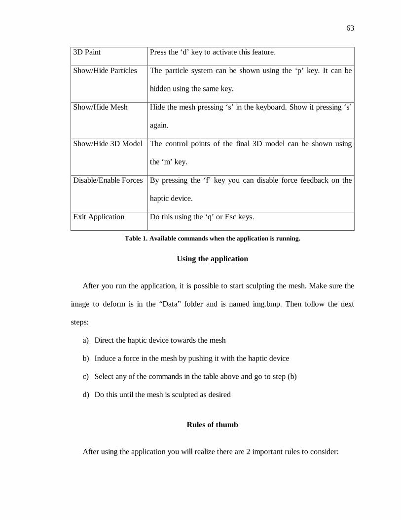
3D Paint Press the ‘d’ key to activate this feature.
Show/Hide Particles The particle system can be shown using the ‘p’ key. It can be
hidden using the same key.
Show/Hide Mesh Hide the mesh pressing ‘s’ in the keyboard. Show it pressing ‘s’
again.
Show/Hide 3D Model The control points of the final 3D model can be shown using
the ‘m’ key.
Disable/Enable Forces By pressing the ‘f’ key you can disable force feedback on the
haptic device.
Exit Application Do this using the ‘q’ or Esc keys.
Table 1. Available commands when the application is running.
Using the application
After you run the application, it is possible to start sculpting the mesh. Make sure the
image to deform is in the “Data” folder and is named img.bmp. Then follow the next
steps:
a) Direct the haptic device towards the mesh
b) Induce a force in the mesh by pushing it with the haptic device
c) Select any of the commands in the table above and go to step (b)
d) Do this until the mesh is sculpted as desired
Rules of thumb
After using the application you will realize there are 2 important rules to consider:
64
a) You should increase the height of the image slowly as a whole. In other words,
you should not move each section to their final height individually. Better
results are created if the image as a whole is deformed and all the sections get
to their final height almost at the same time.
b) Edges are difficult to create since NURBS surfaces are inherently smooth.
However, the knot array we defined gives us some flexibility. If you want to
create an edge you should first push the part of the image that will be in the
bottom –it does not matter if you do not push the exact portion of the image,
the next step pulls it back-. The next step is to pull the portion that will be in
the top. Then repeat these two steps until the edge is visible.