Embed Size (px)
Citation preview

B-1
IndexSECTION B
BUSH
INGS
INTERCHANGEABLE BUSHINGSPRODUCT PAGE
INDEX . . . . . . . . . . . . . . . . . . . . . . . . . . . . . . . . . . . . . . . . . . . . . . . . . . . . . . . . . . . . . . . . . . . . . . . . . . . . . . . . . . . B-1
BUSHING TYPES . . . . . . . . . . . . . . . . . . . . . . . . . . . . . . . . . . . . . . . . . . . . . . . . . . . . . . . . . . . . . . . . . . . . . . . . . . B-2
QD
Installation/Removal . . . . . . . . . . . . . . . . . . . . . . . . . . . . . . . . . . . . . . . . . . . . . . . . . . . . . . . . . . . . . . . . . . B-3
Steel Bushing . . . . . . . . . . . . . . . . . . . . . . . . . . . . . . . . . . . . . . . . . . . . . . . . . . . . . . . . . . . . . . . . . . . . . . . B-4
Standard Bushing . . . . . . . . . . . . . . . . . . . . . . . . . . . . . . . . . . . . . . . . . . . . . . . . . . . . . . . . . . . . . . . . . . . . B-5
Weld-On Hubs . . . . . . . . . . . . . . . . . . . . . . . . . . . . . . . . . . . . . . . . . . . . . . . . . . . . . . . . . . . . . . . . . . . . . . B-6
TAPER BUSHING
Installation/Removal . . . . . . . . . . . . . . . . . . . . . . . . . . . . . . . . . . . . . . . . . . . . . . . . . . . . . . . . . . . . . . . . . . B-7
1008 — 3030 . . . . . . . . . . . . . . . . . . . . . . . . . . . . . . . . . . . . . . . . . . . . . . . . . . . . . . . . . . . . . . . . . . . . . . . B-8
3535 — 5050 . . . . . . . . . . . . . . . . . . . . . . . . . . . . . . . . . . . . . . . . . . . . . . . . . . . . . . . . . . . . . . . . . . . . . . . B-9
6050 — 120100 . . . . . . . . . . . . . . . . . . . . . . . . . . . . . . . . . . . . . . . . . . . . . . . . . . . . . . . . . . . . . . . . . . . . B-10
Weld-On Hubs . . . . . . . . . . . . . . . . . . . . . . . . . . . . . . . . . . . . . . . . . . . . . . . . . . . . . . . . . . . . . . . . . . . . . B-11
Reborable Bushings . . . . . . . . . . . . . . . . . . . . . . . . . . . . . . . . . . . . . . . . . . . . . . . . . . . . . . . . . . . . . . . . . B-12
MST BUSHING
Bushing Specifications . . . . . . . . . . . . . . . . . . . . . . . . . . . . . . . . . . . . . . . . . . . . . . . . . . . . . . . . . . . . . . . B-13
Installation & Removal . . . . . . . . . . . . . . . . . . . . . . . . . . . . . . . . . . . . . . . . . . . . . . . . . . . . . . . . . . . . . . . B-14
Weld-On Hubs . . . . . . . . . . . . . . . . . . . . . . . . . . . . . . . . . . . . . . . . . . . . . . . . . . . . . . . . . . . . . . . . . . . . . B-15
IDLER BUSHINGS; QD, MST . . . . . . . . . . . . . . . . . . . . . . . . . . . . . . . . . . . . . . . . . . . . . . . . . . . . . . . . . . . . . . . . B-16
B1-B16 3/27/03 12:18 PM Page 1

TAPER BUSHING(Inch & Metric Bore)
WELD-ON HUBTAPER BUSHEDTYPES S & WA
B-2
BUSHINGS
InterchangeableBushings
WELD-ON HUBTYPE QD
WELD-ON HUBMST – Martin SPLIT TAPER
MST – Martin SPLIT TAPERBUSHING
(Inch & Metric Bore)
QD BUSHING(Inch & metric bore)
Martin’S BUSHING LINE INCLUDES THE MOST POPULAR BUSHINGS USED IN INDUSTRY. WE OFFER QD (QUICK DISCONNECT),
TB (TAPER BUSHED) AND MSTTM (MARTIN SPLIT TAPER) BUSHINGS.
Martin’S BUSHING ARE AVAILABLE IN A VARIETY OF SIZES, STYLES AND MATERIALS.
Martin WELD-ON HUBS ARE MADE OF STEEL AND FIT Martin BUSHINGS.
B1-B16 3/27/03 12:18 PM Page 2

B-3
BUSH
INGS
Stock “QD”Bushings
Martin MOUNTING PROCEDURE – QD BUSHINGSIMPORTANT – BE SURE TAPERED CONE SURFACES OF QD BUSHING AND INSIDE OF SHEAVE OR SPROCKET HUB ARE DRY AND FREE OF ALLFOREIGN SUBSTANCES SUCH AS PAINT, GREASE, OR DIRT.
STANDARD Mounting Assembly FOR QD SHEAVES AND SPROCKETSMOUNTING
1. Be sure the tapered cone surfaces of the bushing and the inside of thedriven product are clean and free of anti-seize lubricants.
2. Slide QD bushing on shaft, flange end first. Assemble key.3. Position QD bushing on shaft. Tighten set screw over key "hand tight"
with standard Allen wrench only. Do not use excessive force.4. Slide large end of sheave or sprocket taper bore into position over cone
aligning drilled bolt holes in sheave or sprocket with tapped holes inflange of bushing. Assemble pull-up bolts and lock washers.NOTE: Install M thru S bushings in the hub so that the two extra holesin the hub are located as far as possible from the bushing's saw cut.
5. Tighten pull-up bolts alternately and evenly to tightness indicated intorque table on back. Do not use extensions on wrench handles. Thereshould be a gap between the face of the sheave or sprocket hub and theflange of the QD bushing to insure a satisfactory cone grip and press fit.CAUTION: THIS GAP MUST NOT BE CLOSED.
DISMOUNTING1. Remove pull-up bolts
and screw them intoTAPPED holes insheave or sprocket andagainst flange of QDbushing to break conegrip.
2. Loosen set screw andslide QD bushing fromshaft.
WARNING: Because of the possible danger to person(s) or property from accidents which may result from the improper use of products, it is important that correctprocedures be followed: Products must be used in accordance with the engineering information specified in the catalog. Proper installation, maintenance and opera-tion procedures must be observed. The instructions given above must be followed. Inspections should be made as necessary to assure safe operation under prevail-ing conditions. All rotating power transmission products when used in a drive are potentially dangerous and must be guarded by the user as required by applicablelaws, regulations, standards, and good safety practice. (Refer to ANSI Standard B15.1.)
TAPERED CONE GRIP
KEY SET SCREW PULL UP BOLTB
A
C
TAPERED CONE GRIP
KEY SET SCREW
B
A
C
PULL UP BOLT
1. Be sure the tapered cone surfaces of the bushing and the inside of the driven product are clean and free of anti-seize lubricants.
2. Assemble sheave or sprocket with bolts inserted (But not tightened) through DRILLED holes in bushing flangeinto TAPPED holes in sheave, sprocket, or other Martin QD part.
3. With key in shaft keyseat, slide assembly into approximate position on shaft with flange end of bushing away frombearing.
4. Position QD bushing on shaft by tightening set screw over key "hand tight" with standard Allen wrench only. Donot use excessive force.
5. Tighten pull-up bolts alternately and evenly to tightness indicated in torque table below. Do not use extensions onwrench handles. There should be a gap between the face of the sheave or sprocket hub and the flange of the QDbushing to insure a satisfactory cone grip and press fit. CAUTION: THIS GAP MUST NOT BE CLOSED.
1. Remove pull-up bolts and screw them into TAPPED holes in bushing flange and against hub of sheave or sprocketto break cone grip.
2. Loosen set screw in bushing flange and slide QD bushing from shaft.
B
A
C
B
A
C
REVERSE Mounting AssemblyFOR QD SHEAVES AND SPROCKETS USING JA, SH, SD, SDS, SK, SF, E, F, & J BUSHINGS
These bushings, as well as the sprockets and sheaves for them, are each drilled with six holes (three drilled and threetapped) to allow pull-up bolts to be inserted from either side. This enables variations of mounting characteristics to suita particular installation.
B1-B16 3/27/03 12:18 PM Page 3
B-4
BUSHINGS
All Steel“QD” Bushings
“QD” Bushings — Steel
Bushings“JA” to “J” Inclusive
Bushings“M” to “S” Inclusive
Reborable QD bushingsmade of Stainless Steel areavailable in many sizes.Non stock sizes areavailable on MTO basis.
★ F = Length of Mating Bore ★★ G = Gap Between “QD” Bushing and Mating Hub
Dimensions (Inches) Stock Bore RangeCap Maximum Average
Bushing A B D E F G L Bolt Screws Standard Shallow WeightCircle Required Minimum Keyway Keyway (Approx.)
Bushing Plain Bores Not Split
Shallow Key Dimension — StandardKey Seat Key Keyway Key
Standard Keyway and Key DimensionBores Keyway Key
SF-STL 9⁄16 3.125 45⁄8 11⁄2 11⁄4 1⁄8 21⁄16 37⁄8 33⁄8 x 2 1⁄2 25⁄16 213⁄16 3.0 E-STL 3⁄4 3.834 6 17⁄8 15⁄8 1
8 25⁄8 5 31⁄2 x 23⁄4 7⁄8 27⁄8 31⁄2 10.0 F-STL 13⁄16 4.437 65⁄8 213⁄16 21⁄2 3⁄16 35⁄8 55⁄8 39⁄16 x 35⁄8 1 35⁄16 4 11.5 J-STL 1 5.148 71⁄4 31⁄2 33⁄16
3⁄16 41⁄2 61⁄4 35⁄8 x 41⁄2 17⁄16 33⁄4 41⁄2 18.0 M-STL 11⁄4 6.500 9 51⁄2 53⁄16
3⁄16 63⁄4 77⁄8 43⁄4 x 63⁄4 2 43⁄4 51⁄2 37.0 N-STL 11⁄2 7.000 10 65⁄8 61⁄4 7⁄18 81⁄8 81⁄2 47⁄8 x 81⁄2 21⁄2 51⁄8 57⁄8 57.0
Bushing Bores Keyway
7⁄8 3⁄16 x 3⁄323⁄16 x 3⁄16
15⁄16 - 11⁄4 1⁄4 x 1⁄8 1⁄4 x 1⁄415⁄16 - 13⁄8 5⁄16 x 5⁄32
5⁄16 x 5⁄16
17⁄16 - 13⁄4 3⁄8 x 3⁄163⁄8 x 3⁄8
113⁄16 - 21⁄4 1⁄2 x 1⁄4 1⁄2 x 1⁄225⁄16 - 23⁄4 5⁄8 x 5⁄16
5⁄8 x 5⁄8213⁄16 - 31⁄4 3⁄4 x 3⁄8 3⁄4 x 3⁄435⁄16 - 33⁄4 7⁄8 x 7⁄16
7⁄8 x 7⁄8313⁄16 - 41⁄2 1 x 1⁄2 1 x 1 49⁄16 - 51⁄2 11⁄4 x 5⁄8 11⁄4 x 11⁄459⁄16 - 61⁄2 11⁄2 x 3⁄4 11⁄2 x 11⁄269⁄16 - 71⁄2 13⁄4 x 3⁄4 13⁄4 x 11⁄279⁄16 - 9 2 x 3⁄4 21⁄2 x 11⁄2
91⁄16 - 11 21⁄2 x 7⁄8 ——111⁄16 - 13 3 x 1 ——
1⁄4 x 1⁄321⁄4 x 5⁄32
3⁄4 x 1⁄8 3⁄4 x 1⁄21⁄4 x 1⁄16
1⁄4 x 3⁄167⁄8 x 1⁄16
7⁄8 x 1⁄23⁄8 x 1⁄32
3⁄8 x 7⁄327⁄8 x 3⁄16
7⁄8 x 5⁄83⁄8 x 1⁄16
3⁄8 x 1⁄4 1 x 1⁄8 1 x 5⁄83⁄8 x 1⁄8 3⁄8 x 5⁄16 11⁄4 x 1⁄4 11⁄4 x 7⁄8
1⁄2 x 1⁄321⁄2 x 9⁄32 11⁄2 x 1⁄8 11⁄2 x 7⁄8
1⁄2 x 1⁄161⁄2 x 5⁄16 11⁄2 x 1⁄4 11⁄2 x 1
1⁄2 x 1⁄8 1⁄2 x 3⁄8 13⁄4 x 1⁄8 13⁄4 x 3⁄45⁄8 x 1⁄16
5⁄8 x 3⁄8 13⁄4 x 1⁄4 13⁄4 x 7⁄83⁄4 x 1⁄16
3⁄4 x 7⁄16 2 x 1⁄4 2 x 1
1⁄4 x 1⁄321⁄4 x 5⁄32
3⁄4 x 1⁄163⁄4 x 7⁄16
1⁄4 x 1⁄161⁄4 x 3⁄16
3⁄4 x 1⁄8 3⁄4 x 1⁄23⁄8 x 1⁄32
3⁄8 x 7⁄327⁄8 x 1⁄16
7⁄8 x 1⁄23⁄8 x 1⁄16
3⁄8 x 1⁄4 7⁄8 x 3⁄167⁄8 x 5⁄8
3⁄8 x 1⁄8 3⁄8 x 5⁄16 1 x 1⁄8 1 x 5⁄81⁄2 x 1⁄32
1⁄2 x 3⁄32 11⁄4 x 1⁄4 11⁄4 x 7⁄81⁄2 x 1⁄16
1⁄2 x 5⁄16 11⁄2 x 1⁄4 11⁄2 x 1 1⁄2 x 1⁄8 1⁄2 x 3⁄8 13⁄4 x 1⁄8 13⁄4 x 3⁄4
5⁄8 x 1⁄165⁄8 x 3⁄8 13⁄4 x 3⁄8 13⁄4 x 1
5⁄8 x 3⁄165⁄8 x 1⁄2 2 x 1⁄4 2 x 1
SH-STL 1⁄2SD-STL 1⁄2SK-STL 1⁄2SF-STL 115⁄16
E-STL 7⁄8 - 115⁄16
F-STL 1 - 27⁄16 - 215⁄16
J-STL 17⁄16 - 215⁄16
M-STL 2 - 215⁄16
N-STL 27⁄16 - 415⁄16
SF-STL
23⁄8 - 29⁄165⁄8 x 3⁄16
25⁄8 - 23⁄4 5⁄8 x 1⁄16
213⁄16 - 27⁄8 3⁄4 x 1⁄16
215⁄163⁄4 x 1⁄32
7⁄8 - 27⁄8 STD.E-STL 215⁄16 - 31⁄4 3⁄4 x 1⁄8
35⁄16 - 31⁄2 7⁄8 x 1⁄16
F-STL
1 - 35⁄16 STD.33⁄8 - 33⁄4 7⁄8 x 3⁄16
37⁄8 - 315⁄16 1 x 1⁄84 NONE
J-STL 37⁄16 - 33⁄4 STD.313⁄16 - 41⁄2 1 x 1⁄8
2 - 43⁄4 STD. M-STL 413⁄16 - 51⁄2 11⁄4 x 1⁄4
21⁄2 - 51⁄8 STD.N-STL 53⁄16 - 51⁄2 11⁄4 x 1⁄4
59⁄16 - 57⁄8 11⁄2 x 1⁄4 Shallow Key Dimension — SteelKey Seat Key Keyway Key
B1-B16 3/27/03 12:18 PM Page 4

BUSH
INGS
3⁄8 - 7⁄16 NO K.W.1⁄2 - 1 STD.
JA 11⁄18 - 11⁄8 1⁄4 - 1⁄16
13⁄161⁄4 - 1⁄16
11⁄4 NO K.W.1⁄2 - 13⁄8 STD
SH 17⁄16 - 11⁄2 3⁄8 x 1⁄16
19⁄16 - 15⁄8 3⁄8 - 1⁄16
111⁄16 NO K.W.1⁄2 - 111⁄16 STD.
13⁄4 3⁄8 x 1⁄8SDS 113⁄16
1⁄2 x 1⁄817⁄8 - 115⁄16
1⁄2 x 1⁄16
2 NO K.W.1⁄2 - 111⁄16 STD.
13⁄4 3⁄8 x 1⁄8
SD 113⁄161⁄2 x 1⁄8
17⁄8 1⁄2 x 1⁄16
115⁄161⁄2 x 1⁄16
2 NO K.W.1⁄2 - 21⁄8 STD.
SK 23⁄16 - 21⁄4 1⁄2 x 1⁄825⁄16 - 21⁄2 5⁄8 x 1⁄16
29⁄16 - 25⁄8 NO K.W. 1⁄2 - 21⁄4 STD.
SF 25⁄16 - 21⁄2 5⁄8 x 3⁄16
29⁄16 - 23⁄4 5⁄8 x 1⁄16
213⁄16 - 27⁄8 3⁄4 x 1⁄16
215⁄163⁄4 x 1⁄32
7⁄8 - 27⁄8 STD. E 215⁄16 - 31⁄4 3⁄4 x 1⁄8
33⁄8 - 31⁄2 7⁄8 x 1⁄16
35⁄167⁄8 x 1⁄8
1 - 35⁄16 STD.
F33⁄8 - 33⁄4 7⁄8 x 3⁄16
37⁄8 - 315⁄16 1 x 1⁄84 NONE
J 11⁄4 - 33⁄4 STD. 313⁄16 - 41⁄2 1 x 1⁄8
M 2 - 43⁄4 STD. 413⁄16 - 51⁄2 11⁄4 x 1⁄427⁄16 - 5 STD.
N 51⁄8 - 51⁄2 11⁄4 x 1⁄459⁄16 - 6 11⁄2 x 1⁄4
215⁄16 - 515⁄16 STD. P 6 - 61⁄2 11⁄2 x 1⁄4
69⁄16 - 7 13⁄4 x 1⁄8
W 4 - 71⁄2 STD. 79⁄16 - 81⁄2 2 x 1⁄4
Inch Bore Millimeter Bore
★ Important — The metric system does not refer tokeyseat or keyway dimensions as does theEnglish system; instead dimensions are given forthe key itself which is rectangular in shape, notsquare as in the English system.
NOTE: .03937″=1mmEx—24 mm = 0.94488″
Dimensions (Inches) Stock Bore RangeCap Maximum Average
Bushing A B D E F G L Bolt Screws Standard Shallow Set Screw WeightCircle Required Minimum Keyway Keyway Size (Approx.)
JA 3⁄8 1.375 2 11⁄169⁄16
1⁄8 11⁄16 1.665 3-10 x 1 3⁄8 1 11⁄4 10-24 .9 SH 7⁄16 1.871 211⁄16
7⁄8 13⁄161⁄8 15⁄16 21⁄4 3-1⁄4 x 13⁄8 1⁄2 13⁄8 111⁄16
1⁄4 1SDS 1⁄2 2.187 33⁄16
7⁄8 3⁄4 1⁄8 13⁄8 211⁄16 3-1⁄4 x 13⁄8 1⁄2 111⁄16 2 1⁄4 1 SD 1⁄2 2.187 33⁄16 15⁄16 11⁄4 1⁄8 113⁄16 211⁄16 3-1⁄4 x 17⁄8 1⁄2 111⁄16 115⁄16
1⁄4 1.5 SK 9⁄16 2.812 37⁄8 13⁄8 11⁄4 1⁄8 115⁄16 35⁄16 3-5⁄16 x 2 1⁄2 21⁄8 21⁄2 5⁄16 2 SF 9⁄16 3.125 45⁄8 11⁄2 11⁄4 1⁄8 21⁄16 37⁄8 3-3⁄8 x 2 1⁄2 25⁄16 213⁄16
5⁄16 3 E 3⁄4 3.834 6 17⁄8 15⁄8 1⁄8 25⁄8 5 3-1⁄2 x 23⁄4 7⁄8 27⁄8 31⁄2 3⁄8 10 F 13⁄16 4.437 65⁄8 213⁄16 21⁄2 3⁄16 35⁄8 55⁄8 3-9⁄16 x 35⁄8 1 35⁄16 315⁄16
1⁄2 11.5 J 1 5.148 71⁄4 31⁄2 33⁄16
3⁄16 41⁄2 61⁄4 3-5⁄8 x 41⁄2 17⁄16 33⁄4 41⁄2 5⁄8 18 M 11⁄4 6.500 9 51⁄2 53⁄16
3⁄16 63⁄4 77⁄8 4-3⁄4 x 63⁄4 115⁄16 43⁄4 51⁄2 3⁄4 37 N 11⁄2 7.000 101⁄4 65⁄8 61⁄4 1⁄4 81⁄8 81⁄2 4-7⁄8 x 81⁄2 27⁄16 51⁄8 6 3⁄4 57 P 13⁄4 8.250 113⁄4 75⁄8 71⁄4 1⁄4 93⁄8 10 4-1 x 91⁄2 215⁄16 515⁄16 7 7⁄8 120 W 2 10.437 15 93⁄8 9 1⁄4 113⁄8 123⁄4 4-11⁄8 x 111⁄2 4 71⁄2 81⁄2 1 250 S 31⁄4 12.125 173⁄4 121⁄2 12 3⁄8 153⁄4 15 5-11⁄4 x 151⁄2 6 81⁄4 10 11⁄4 400
Bushing Bores Keyway
24, 25 8x7 SH 28, 30
32, 35 10x8 24, 25 28, 30 8x7
SDS 32, 35 10x8 38
40, 42 12x8 24, 25 8x7 28, 30
SD 32, 35 10x8 38
40, 42 12x8 24, 25 8x7 28, 30 32, 35 10x8
SK 38 40, 42 12x8 48, 50 14x9
55 16x10 28, 30 8x7 32, 35 10x8
38 SF 40, 42 12x8
48, 50 14x9 55 16x10 60 18x11
35, 38 10x8 40, 42 12x8
E 48, 50 14x9 55 16x10
60, 65 18x11 70, 75 20x12 48, 50 14x9
55 16x10 F 60, 65 18x11
70, 75 20x12 80, 85 22x14
90 25x14 50 14x9 55 16x10
60, 65 18x11 J 70, 75 20x12
80, 85 22x14 90, 95 25x14 100 28x16
TO ORDER: SH 24 mm
Bore Key★Bushing MM WXT
Keystock provided for nonstandard keyways.
B-5
Standard“QD” Bushings
B1-B16 3/27/03 12:18 PM Page 5

B-6
BUSHINGS
“QD” Weld-On Hubs
WELD-ON HUB TYPE QD
Martin QD weld-on hubs are suitable for use in manyapplications, such as welding to plate steel sprockets.
Weld-on hubs are made of steel, drilled tapped and taperbored for QD bushings
QD Weld-On Hubs
★ Tolerance of D DimensionJA-A Thru J-A = (+.000-.002)M-A Thru S-A = (+.000-.003)
Catalog Dimensions — Inches Type WeightNumber D★ L B P L1 BC Drilling Pounds Mounting
JA-A 2.250 9⁄16 1.375 — — 121⁄32 1 .4 SH-A 3.000 13⁄16 1.871 — — 21⁄4 1 1
SDS-A 3.500 3⁄4 2.188 — — 211⁄16 1 11⁄4SK-A 4.375 11⁄4 2.813 — — 35⁄16 1 3 SF-A 5.000 11⁄4 3.125 — — 37⁄8 1 4 E-A 6.250 15⁄8 3.832 — — 5 1 9 F-A 7.000 21⁄2 4.437 — — 55⁄8 1 16 J-A 7.750 33⁄16 5.140 — — 61⁄4 1 22.5 M-A 9.500 53⁄16 6.494 9.250 39⁄16 77⁄8 2 50 N-A 10.500 61⁄4 6.990 10.250 41⁄2 81⁄2 2 75 P-A 13.000 71⁄4 8.240 — — 10 2 155 W-A 15.500 9 10.437 — — 123⁄4 2 300 S-A 19.500 12 12.125 18.75 7.5 15 2 558
STD orReverseMount
STDMountOnly
D
L
BC
B
D
P
L
BC
B
L1
45°
45°75°
90°
55°35°
TYPE 1 TYPE 2
B1-B16 3/27/03 12:18 PM Page 6

B-7
BUSH
INGS
TaperBushings
IMPORTANT NOTE: Please follow the instructions on this sheet in order for the Martin bushing to perform satisfactorily.
1008 to 3030 3535 to 6050 7060 to 1085 102100
INSTALLATION1 Clean all oil, dirt, and paint from shaft, bushing bore, outside of bushing and component (sprocket, sheave...etc.) bore.2 Insert bushing into component. Match the hole pattern, not the threaded holes (each hole will be threaded on one side only.)3. Thread set or cap screws into those half threaded holes indicated by ❍ on above diagram. Mount assembly on shaft.4. Alternately torque set or cap screws* to recommended torque setting in chart below. 5. On 3535 and larger bushings use a block, sleeve or drift and hammer large end of bushing (do not hammer bushing directly).6. Repeat steps 4 and 5 until torque wrench reading, after hammering, is the same as before hammering.7. Fill all unoccupied holes with grease.
REMOVAL1. Remove all set or cap screws.2. Insert set or cap screws in holes indicated by ● on drawing. Loosen bushing by alternately tightening set or cap screws.3. To reinstall, complete all seven (7) installation instructions.
WARNING: Because of the possible danger to person(s) or property from accidents which may result from theimproper use of products, it is important that correct procedures be followed: Products must be used in accordancewith the engineering information specified in the catalog. Proper installation, maintenance and operation proceduresmust be observed. The instructions given above must be followed. Inspections should be made as necessary toassure safe operation under prevailing conditions. All rotating power transmission products when used in a drive arepotentially dangerous and must be guarded by the user as required by applicable laws, regulations, standards, andgood safety practice. (Refer to ANSI Standard B15.1.)
RECOMMENDED TORQUE TABLE
1008, 1108 1/4 - 20 Socket Set Screw 551210, 1215, 1310 3/8 - 16 Socket Set Screw 175
1610, 1615 3/8 - 16 Socket Set Screw 175
2012 7/16 - 14 Socket Set Screw 2802517, 2525 1/2 - 13 Socket Set Screw 4303020, 3030 5/8 - 11 Socket Set Screw 800
3535 1/2 - 13 Socket Head Cap Screw 1,0004040 5/8 - 11 Socket Head Cap Screw 1,7004545 3/4 - 10 Socket Head Cap Screw 2,450
5050 7/8 - 9 Socket Head Cap Screw 3,1006050, 7060, 8065 1-1/4 -7 Socket Head Cap Screw 7,82010085, 120100 1 - 1/2 - 6 Socket Head Cap Screw 13,700
* If two bushings are used on same component and shaft, fully tighten one bushing before working on the other.
Bushing No. Set or Cap ScrewWrench Torque
in. / lbs.CAUTION
WARNING: USE OF ANTI-SEIZE LUBRICANT ON TAPERED CONE SURFACES OR ON BOLT THREADS WHEN MOUNTING MAY RESULT IN DAMAGE TO SHEAVES AND SPROCKETS. THIS VOIDS ALL MANUFACTURER'S WARRANTIES.
B1-B16 3/27/03 12:18 PM Page 7

B-8
BUSHINGS
Taper BushingsDimensions
Bushings cannot be bored larger than largest bore listed.
For detail dimensions required for machining hubs, consult factory.
∆ Key furnished for these sizes only.
Ø For general reference. Severe conditions may require larger hub. Heavy well-located web may permitsmaller hub. Hub diameter required depends on the particular application. Consult Martin giving full information on the proposed design. Hub diameters shown are based on 20,000, 30,000, and 50,000P.S.I. minumum ultimate tensile strength respectively for Class 20 gray iron, Class 30 gray iron, andsteel hubs.
† 2 screws required. Use in positions shown for tightening bushing on shaft. In removing bushing fromshaft, remove screws and use one of them in the other hole. Bushing price includes screws.
★ Space required to tighten bushing. Also space required to loosen screws to permit removal of hub by puller.
★★ Space required to loosen bushing using one screw as jackscrew — no puller required.
‡ Standard hex key cut to minimum usable length.
No. 1008 to 3030 Taper BushingsBushing Bushing ShaftNumber Bore Wt. Keyseat Keyseat
1⁄2 to 9⁄16 .27 1⁄8 x 1⁄161⁄8 x 1⁄16
1008 5⁄8 to 7⁄8 .21 3⁄16 x 3⁄323⁄16 x 3⁄32
15⁄16 to 1 .16 1⁄4 x 1⁄16 ∆ 1⁄4 x 1⁄81⁄2 to 9⁄16 .33 1⁄8 x 1⁄16
1⁄8 x 1⁄16
1108 5⁄8 to 7⁄8 .27 3⁄16 x 3⁄323⁄16 x 3⁄32
15⁄16 to 1 .22 1⁄4 x 1⁄8 1⁄4 x 1⁄811⁄16 to 11⁄8 .17 1⁄4 x 1⁄16 ∆ 1⁄4 x 1⁄8
1⁄2 to 9⁄16 .61 1⁄8 x 1⁄161⁄8 x 1⁄16
1210 5⁄8 to 7⁄8 .55 3⁄16 x 3⁄323⁄16 x 3⁄32
15⁄16 to 11⁄4 .49 1⁄4 x 1⁄8 1⁄4 x 1⁄81⁄2 to 9⁄16 .8 1⁄8 x 1⁄16
1⁄8 x 1⁄16
1215 5⁄8 to 7⁄8 .7 3⁄16 x 3⁄323⁄16 x 3⁄32
15⁄16 to 11⁄4 .6 1⁄4 x 1⁄8 1⁄4 x 1⁄81⁄2 to 9⁄16 .7 1⁄8 x 1⁄16
1⁄8 x 1⁄16
1310 5⁄8 to 7⁄8 .7 3⁄16 x 3⁄323⁄16 x 3⁄32
15⁄16 to 11⁄4 .6 1⁄4 x 1⁄8 1⁄4 x 1⁄815⁄16 to 13⁄8 .6 5⁄16 x 5⁄32
5⁄16 x 5⁄32
1⁄2 to 9⁄16 .9 1⁄8 x 1⁄161⁄8 x 1⁄16
5⁄8 to 7⁄8 .8 3⁄163⁄32
3⁄163⁄32
1610 15⁄16 to 11⁄4 .7 1⁄4 x 1⁄8 1⁄4 x 1⁄815⁄16 to 13⁄8 .7 5⁄16 x 5⁄32
5⁄16 x 5⁄32
17⁄16 to 11⁄2 .6 3⁄8 x 3⁄163⁄8 x 3⁄16
19⁄16 to 15⁄8 .5 3⁄8 x 1⁄8 ∆ 3⁄8 x 3⁄16
1⁄2 to 9⁄16 1.2 1⁄8 x 1⁄161⁄8 x 1⁄16
5⁄8 to 7⁄8 1.1 3⁄16 x 3⁄323⁄16 x 3⁄32
1615 15⁄16 to 11⁄4 1.0 1⁄4 x 1⁄8 1⁄4 x 1⁄815⁄16 to 13⁄8 .8 5⁄16 x 5⁄32
5⁄16 x 5⁄32
17⁄16 to 11⁄2 .7 3⁄8 x 3⁄163⁄8 x 3⁄16
19⁄16 to 15⁄8 .6 3⁄8 x 1⁄8 ∆ 3⁄8 x 3⁄16
1⁄2 to 9⁄16 1.7 1⁄8 x 1⁄161⁄8 x 1⁄16
5⁄8 to 7⁄8 1.6 3⁄16 x 3⁄323⁄16 x 3⁄32
15⁄16 to 11⁄4 1.5 1⁄4 x 1⁄8 ∆ 1⁄4 x 1⁄82012 15⁄16 to 13⁄8 1.4 5⁄16 x 5⁄32
5⁄16 x 5⁄32
17⁄16 to 13⁄4 1.2 3⁄8 x 3⁄163⁄8 x 3⁄16
113⁄16 to 17⁄8 1.0 1⁄2 x 1⁄4 1⁄2 x 1⁄4115⁄16 to 2 1.0 1⁄2 x 3⁄16 ∆ 1⁄2 x 1⁄4
1⁄2 to 9⁄16 3.5 1⁄8 x 1⁄161⁄8 x 1⁄16
5⁄8 to 7⁄8 3.4 3⁄16 x 3⁄323⁄16 x 3⁄32
15⁄16 to 11⁄4 3.3 1⁄4 x 1⁄8 1⁄4 x 1⁄82517 15⁄16 to 13⁄8 3.2 5⁄16 x 5⁄32
5⁄16 x 5⁄32
17⁄16 to 13⁄4 3.0 3⁄8 x 3⁄163⁄8 x 3⁄16
113⁄16 to 21⁄4 2.4 1⁄2 x 1⁄4 1⁄2 x 1⁄425⁄16 to 21⁄2 1.9 5⁄8 x 3⁄16 ∆ 5⁄8 x 5⁄16
3⁄4 to 7⁄8 4.9 3⁄16 x 3⁄323⁄16 x 3⁄32
15⁄16 to 11⁄4 4.7 1⁄4 x 1⁄8 1⁄4 x 1⁄82525 15⁄16 to 13⁄8 4.5 5⁄16 x 5⁄32
5⁄16 x 5⁄32
17⁄16 to 13⁄4 4.2 3⁄8 x 3⁄163⁄8 x 3⁄16
113⁄16 to 21⁄4 3.3 1⁄2 x 1⁄4 1⁄2 x 1⁄425⁄16 to 21⁄2 2.5 5⁄8 x 3⁄16 ∆ 5⁄8 x 5⁄16
15⁄16 to 11⁄4 6.5 1⁄4 x 1⁄8 1⁄4 x 1⁄815⁄16 to 13⁄8 6.3 5⁄16 x 5⁄32
5⁄16 x 5⁄32
3020 17⁄16 to 13⁄4 6.0 3⁄8 x 3⁄163⁄8 x 3⁄16
113⁄16 to 21⁄4 5.3 1⁄2 x 1⁄4 1⁄2 x 1⁄4
25⁄16 to 23⁄4 4.5 5⁄8 x 5⁄165⁄8 x 5⁄16
213⁄16 to 3 3.9 3⁄4 x 1⁄4 ∆ 3⁄4 x 3⁄815⁄16 to 11⁄4 9.2 1⁄4 x 1⁄8 1⁄4 x 1⁄815⁄16 to 13⁄8 8.9 5⁄16 x 5⁄32
5⁄16 x 5⁄32
3030 17⁄16 to 13⁄4 8.6 3⁄8 x 3⁄163⁄8 x 3⁄16
113⁄16 to 21⁄4 7.6 1⁄2 x 1⁄4 1⁄2 x 1⁄425⁄16 to 23⁄4 6.2 5⁄8 x 5⁄16
5⁄8 x 5⁄16
213⁄16 to 3 5.0 3⁄4 x 1⁄4 ∆ 3⁄4 x 3⁄8
1008 1.386 7⁄8 23⁄8 23⁄16 115⁄16 121⁄641⁄4 x 1⁄2 11⁄8 5⁄8 11⁄4 3⁄4
1108 1.511 7⁄8 21⁄2 25⁄16 21⁄16 129⁄641⁄4 x 1⁄2 11⁄8 5⁄8 11⁄4 3⁄4
1210 17⁄8 1 35⁄8 31⁄4 27⁄8 13⁄4 3⁄8 x 5⁄8 13⁄8 13⁄16 15⁄8 11⁄16
1215 17⁄8 11⁄2 31⁄8 27⁄8 25⁄8 13⁄4 3⁄8 x 5⁄8 13⁄8 13⁄16 15⁄8 11⁄16
1310 2 1 33⁄4 33⁄8 3 17⁄8 3⁄8 x 5⁄8 13⁄8 13⁄16 15⁄8 11⁄16
1610 21⁄4 1 4 35⁄8 31⁄4 21⁄8 3⁄8 x 5⁄8 13⁄8 13⁄16 15⁄8 11⁄16
1615 21⁄4 11⁄2 31⁄2 31⁄4 3 21⁄8 3⁄8 x 5⁄8 13⁄8 13⁄16 15⁄8 11⁄16
2012 23⁄4 11⁄4 43⁄4 43⁄8 37⁄8 25⁄8 7⁄16 x 7⁄8 19⁄1615⁄16 2 13⁄8
2517 33⁄8 13⁄4 51⁄2 47⁄8 43⁄8 31⁄4 1⁄2 x 1 15⁄8 1 21⁄4 15⁄82525 33⁄8 21⁄2 43⁄4 41⁄2 41⁄4 31⁄4 1⁄2 x 1 15⁄8 1 21⁄4 15⁄83020 41⁄4 2 7 61⁄4 55⁄8 4 5⁄8 x 11⁄4 113⁄16 13⁄16 211⁄16 21⁄16
3030 41⁄4 3 61⁄4 53⁄4 53⁄8 4 5⁄8 x 11⁄4 113⁄16 13⁄16 211⁄16 21⁄16
DimensionsCØ
Class Class L★ M★★
Bushing 20 30 Standard StandardNumber A B Gray Gray Steel D F† Hex. Short Hex. Short
Iron Iron Key Key‡ Key Key‡
B1-B16 3/27/03 12:18 PM Page 8

B-9
BUSH
INGS
B-9
No. 3535 to 5050 Bushings
Bushings cannot be bored larger than largest bore listed.
For detail dimensions required for machining hubs, consult factory.
∆ Key furnished for these sizes only.
Ø For general reference. Severe conditions may require larger hub. Heavy well-located web may permit smaller hub. Hub diameter required depends on the particular application. Consult factory giving full information on theproposed design. Hub diameters shown are based on 20,000, 30,000, and 50,000 P.S.I. minumum ultimate tensile strength respectively for Class 20 gray iron, Class 30 gray iron, and steel hubs.
† 3 screws required. Use in positions shown for tightening bushing on shaft. In removing bushing from shaft, remove screws and use two of them in theother two holes. Bushing price includes screws. See following footnote.
▲ Provide sufficient space to tighten and loosen bushing. Width across flats of screw head is same as screw diameter which is shown in column F.
Taper BushingsDimensions
3535 13⁄16 to 11⁄4 14 1⁄4 x 1⁄8 1⁄4 x 1⁄815⁄16 to 13⁄8 14 5⁄16 x 5⁄32
5⁄16 x 5⁄32
17⁄16 to 13⁄4 13 3⁄8 x 3⁄163⁄8 x 3⁄16
113⁄16 to 21⁄4 12 1⁄2 x 1⁄4 1⁄2 x 1⁄4 5 31⁄2 73⁄4 7 61⁄2 4.83 1⁄2 x 11⁄2 39° ▲25⁄16 to 23⁄4 11 5⁄8 x 5⁄16
5⁄8 x 5⁄16
213⁄16 to 31⁄4 9 3⁄4 x 3⁄8 3⁄4 x 3⁄835⁄16 to 31⁄2 8 ∆7⁄8 x 1⁄4 7⁄8 x 7⁄16
4040 17⁄16 to 13⁄4 22 3⁄8 x 3⁄163⁄8 x 3⁄16
113⁄16 to 21⁄4 21 1⁄2 x 1⁄4 1⁄2 x 1⁄425⁄16 to 23⁄4 19 5⁄8 x 5⁄16
5⁄8 x 5⁄16
213⁄16 to 31⁄4 17 3⁄4 x 3⁄8 3⁄4 x 3⁄8 53⁄4 4 91⁄2 81⁄2 73⁄4 5.54 5⁄8 x 13⁄4 40° ▲35⁄16 to 35⁄8 15 7⁄8 x 7⁄16
7⁄8 x 7⁄16
311⁄16 to 33⁄4 14 ∆7⁄8 x 1⁄4 7⁄8 x 7⁄16
313⁄16 to 4 13 ∆1 x 1⁄4 1 x 1⁄24545 115⁄16 to 21⁄4 30 1⁄2 x 1⁄4 1⁄2 x 1⁄4
25⁄16 to 23⁄4 28 5⁄8 x 5⁄165⁄8 x 5⁄16
213⁄16 to 31⁄4 26 3⁄4 x 3⁄8 3⁄4 x 3⁄8 63⁄8 41⁄2 101⁄2 91⁄2 83⁄4 6.13 3⁄4 x 2 40° ▲35⁄16 to 33⁄4 23 7⁄8 x 7⁄16
7⁄8 x 7⁄16
313⁄16 to 41⁄4 20 1 x 1⁄2 1 x 1⁄245⁄16 to 41⁄2 18 ∆1 x 1⁄4 1 x 1⁄2
5050 25⁄16 to 23⁄4 38 5⁄8 x 5⁄165⁄8 x 5⁄16
213⁄16 to 31⁄4 35 3⁄4 x 3⁄8 3⁄4 x 3⁄835⁄16 to 33⁄4 32 7⁄8 x 7⁄16
7⁄8 x 7⁄16 7 5 111⁄2 101⁄2 91⁄2 6.72 7⁄8 x 21⁄4 37° ▲313⁄16 to 41⁄2 27 1 x 1⁄2 1 x 1⁄249⁄16 to 5 24 ∆11⁄4 x 7⁄16 11⁄4 x 5⁄8
CØClass Class
Bushing Bore Weight Bushing Shaft A B 20 30 Steel D F† G RNumber Keyseat Keyseat Gray Iron Gray Iron
B1-B16 3/27/03 12:18 PM Page 9
B-10
BUSHINGS
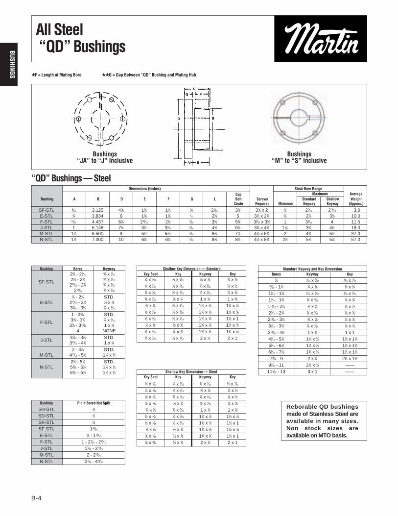
Taper BushingsDimensions
Bushings cannot be bored larger than largest bore listed.
For detail dimensions required for machining hubs, consult Martin.
Ø For general reference. Severe conditions may require larger hub. Heavy well-located web may permit smaller hub. Hub diameter required depends on theparticular application. Consult Martin giving full information on the pro-posed design. Hub diameters shown are based on 20,000, 30,000, and50,000 P.S.I. minumum ultimate tensile strength respectively for Class 20gray iron, Class 30 gray iron, and steel hubs.
† 3 screws for 6050; four for 7060 to 10085; six for 120100. Use in positions shown for tightening bushing on shaft. In loosening bushing, remove
screws and use all except one in the other holes. Bushing price includesscrews.
★ Space required to tighten bushing. Also space required to loosen screws to ` permit removal of hub by puller.
★★ Space required to loosen bushing using screws as jackscrews— no puller required.
Φ Not currently stocked — Available on order.
6050 313⁄16 to 41⁄2 60 1 x 1⁄2 1 x 1⁄249⁄16 to 51⁄2 55 11⁄4 x 5⁄8 11⁄4 x 5⁄8 91⁄4 5 17 151⁄2 131⁄2 9 63⁄4 11⁄4 x 31⁄2 15⁄8 43⁄859⁄16 to 6 50 11⁄2 x 3⁄4 11⁄2 x 3⁄4
7060 49⁄16 to 51⁄2 85 11⁄4 x 5⁄8 11⁄4 x 5⁄859⁄16 to 61⁄2 75 11⁄2 x 3⁄4 11⁄2 x 3⁄4 101⁄4 6 181⁄2 17 143⁄4 10 73⁄4 11⁄4 x 31⁄2 15⁄8 43⁄869⁄16 to 7 65 13⁄4 x 3⁄4 13⁄4 x 3⁄4
Φ8065 51⁄16 to 51⁄2 120 11⁄4 x 5⁄8 11⁄4 x 5⁄859⁄16 to 61⁄2 105 11⁄2 x 3⁄4 11⁄2 x 3⁄4 111⁄4 61⁄2 19 171⁄2 151⁄2 11 83⁄4 11⁄4 x 31⁄2 15⁄8 43⁄869⁄16 to 71⁄2 90 13⁄4 x 3⁄4 13⁄4 x 3⁄479⁄16 to 8 75 2 x 3⁄4 2 x 3⁄4
Φ10085 69⁄16 to 71⁄2 260 13⁄4 x 3⁄4 13⁄4 x 3⁄479⁄16 to 9 230 2 x 3⁄4 2 x 3⁄4 143⁄4 81⁄2 231⁄2 22 191⁄2 141⁄2 113⁄4 11⁄2 x 41⁄4 2 53⁄8
91⁄16 to 10 190 21⁄2 x 7⁄8 21⁄2 x 7⁄8Φ120100 79⁄16 to 9 410 2 x 3⁄4 2 x 3⁄4
91⁄16 to 11 360 21⁄2 x 7⁄8 21⁄2 x 7⁄8 171⁄4 10 28 26 23 17 141⁄4 11⁄2 x 41⁄4 2 53⁄8111⁄16 to 12 290 3 x 1 3 x 1
No 6050 to 120100 Taper BushingsCØ
Class ClassBush Bore Weight Bushing Shaft A B 20 30 Steel D E F† L★ M★★
Number Keyseat Keyseat Gray Iron Gray Iron
6050 7060 TO 10085
NO. 120100
B1-B16 3/27/03 12:18 PM Page 10

Martin Taper Bushed Type S Weld-On Hubs are suitable for use in many applicationssuch as for welding to plate steel sprockets. The outside diameters of these hubshave been reduced to a minimum. This is permissible because of the reinforcingstrength of the items to which they are to be welded. Cases where the attached itemis of small dimensions should be referred to Martin.
Type S Weld-On Hubs are made of steel, drilled, tapped, and taper bored for TaperedBushings. Their small size and the convenience and advantages of Taper Bushedconstruction make them of great value on many devices for use on shafts.
B-11
BUSH
INGS
Taper Bushed Type S-Type WWeld-On Hubs Dimensions
Type W Weld-On Hubs are made of steel, drilled, tapped, and taper bored to receiveTapered Bushings. They are very useful for welding into fan rotors, pulleys, platesprockets, impellers, agitators, and many other devices which must be firmly fas-tened to the shaft.
WA12 To WA50 WA60 To WA100
See dimension tables on preceeding page for bushing data and wrench space required.† + .000-.002• + .000-.003★ + .000-.004
See dimension tables on preceeding page for bushing data and wrench space required.† + .000-.002Φ + .005-.010Ø + .001-.003∆ + .000-.005★★ + .010-.010
Taper Bushed Type WA Weld-On Hubs
Taper Bushed Type S Weld-On Hubs
Type S
Type WA
S16-4 1610 15⁄8 .9 3 1 .275 .725 27⁄8 † 21⁄4S16-6 1610 15⁄8 .9 3 1 .450 .550 27⁄8 † 21⁄4S20-6 2012 2 1.8 39⁄16 11⁄4 .450 .800 37⁄16 † 23⁄4S20-8 2012 2 1.4 39⁄16 11⁄4 .570 .680 37⁄16 † 23⁄4S25-6 2517 21⁄2 2.6 41⁄4 13⁄4 .450 1.300 41⁄8 † 33⁄8S25-8 2517 21⁄2 2.6 41⁄4 13⁄4 .565 1.185 41⁄8 † 33⁄8
S25-10 2517 21⁄2 2.5 41⁄4 13⁄4 .685 1.065 41⁄8 † 33⁄8S25-16 2517 21⁄2 2.4 41⁄4 13⁄4 1.090 .660 41⁄8 † 33⁄8S30-10 3020 3 4.3 51⁄4 2 .675 1.325 51⁄8 † 41⁄4S30-16 3020 3 4.2 51⁄4 2 1.090 .910 51⁄8 † 41⁄4
S35 3535 31⁄2 12.8 61⁄2 31⁄2 1.160 2.340 63⁄8 Ø 5
WA12 1215 11⁄4 1.3 27⁄8 11⁄2 3⁄8 5⁄8 3⁄8 21⁄2† 23⁄8 17⁄8 25⁄8WA16 1615 15⁄8 1.5 31⁄4 11⁄2 3⁄8 5⁄8 3⁄8 27⁄8† 23⁄4 21⁄4 3WA25 2517 21⁄2 4.0 47⁄8 13⁄4 1⁄2 3⁄4 3⁄8 43⁄8† 41⁄4 33⁄8 45⁄8WA30 3030 3 8.6 51⁄2 3 3⁄4 3⁄4 1⁄4 51⁄8† 413⁄16 41⁄8 5WA35 3535 31⁄2 15 63⁄4 31⁄2 11⁄4 1 3⁄8 61⁄4† 515⁄16 5 6WA40 4040 4 29 73⁄4 4 11⁄2 1 3⁄8 71⁄4† 67⁄8 53⁄4 7WA45 4545 41⁄2 42 83⁄4 41⁄2 13⁄4 1 3⁄8 8† 75⁄8 63⁄8 8WA50 5050 5 57 91⁄2 5 13⁄4 1 3⁄8 83⁄4• 83⁄8 7 83⁄4WA60 6050 6 115 131⁄4 5 13⁄4 11⁄4 121⁄4★ 117⁄8 91⁄4WA70 7060 7 155 141⁄2 6 21⁄4 11⁄4 131⁄2★ 131⁄4 101⁄4WA80 8065 8 180 151⁄4 61⁄2 21⁄4 11⁄4 141⁄4★ 14 111⁄4
WA100 10085 10 340 193⁄4 81⁄2 31⁄2 11⁄2 183⁄4★ 181⁄4 143⁄4
For Use with Max.Hub Bushing Bore of Weight A BΦ C★★ D∆ G J
Number Number Bushing
For Use with Max.Hub Bushing Bore of Weight A B C D F G H J K
Number Number Bushing
B1-B16 3/27/03 12:18 PM Page 11
B-12
BUSHINGS
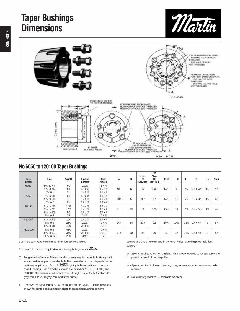
Taper BushingsMetric and Reborable
Stock Taper Bushings With Metric Bores and Keyways
Stock Reborable Taper Bushings With No Keyways
★ Millimeter Bores and Keyways from ISO Std. R773. 1″= 25.4 millimeters
NOTE: For other metric bore sizes consult factory.
14, 16 5 x 2.3 1008 1108 1210 1215 1610 1615
18, 19 6 x 2.8 1008 1108 1210 1215 20, 22 1610 1615 2012 2517
24 8 x 3.3 1108 1210 1215 1610 1615 2012 2517
25 8 x 3.3 1210 1215 1610 1615 2012 2517
28, 30 8 x 3.3 1210 1215 1610 1615 2012 2517 3020
32 10 x 3.3 1610 1615 2012 2517 3020
35 10 x 3.3 1610 1615 2012 2517 3020
38 10 x 3.3 1610 1615 2012 2517 3020
40, 42 12 x 3.3 2012 2517 3020
45, 48 14 x 3.8 2012 2517 3020
50 14 x 3.8 2517 3020 55 16 x 4.3 2517 3020
1008 9⁄16 1008 1⁄2 1008 1⁄21108 1⁄2 1108 1⁄2 1108 1210 9⁄16 1210 1⁄2 1210 1⁄21215 1⁄2 1215 1⁄2 1215 1310 1⁄2 1310 1310 1610 1⁄2 15⁄16 1610 1⁄2 1610 1⁄21615 1⁄2 15⁄16 1615 1⁄2 1615 2012 1⁄2 2012 1⁄2 2012 1⁄22517 1⁄2 19⁄16 2517 1⁄2 2517 1⁄2
2525 21⁄8 2525 2525 3020 15⁄16 111⁄16 3020 15⁄16 17⁄16 215⁄16 3020 15⁄16 3020 15⁄16
3030 15⁄16 27⁄16 215⁄16 3030 3030 3535 13⁄16 27⁄16 215⁄16 3535 3535 4040 17⁄16 37⁄16 315⁄16 4040 4040 4545 315⁄16 47⁄16 4545 4545 5050 27⁄16 315⁄16
6050 37⁄16 57⁄16
7060 315⁄16
8065 47⁄16
10085 7 120100 8
Sintered Steel Gray Iron Steel Stainless Steel
★ Metric ★ MetricBores Keyway Taper Bushing Number
★ Not currently stocked. Consult factory for availability and pricing.
B1-B16 3/27/03 12:18 PM Page 12

B-13
BUSH
INGS
Dimensions Stock Bore Range Cap Screws WrenchPart B Large Av. Wt. TorqueNo. D L A End G B.C. W Type 1 Type 2 No. Size Lbs. In. / lbs.
H 2.50 1.25 0.25 1.6250 0.19 2.00 — 3/8 - 1-3/8 1-7/16 - 1-1/2 2 1/4X3/4 0.8 95 P1 3.00 1.94 0.41 1.9375 0.22 2.44 0.375 1/2 - 1-7/16 1-1/2 - 1-3/4 3 5/16X1 1.3 192 P2 3.00 2.94 0.41 1.9375 0.22 2.44 0.375 3/4 - 1-7/16 1-1/2 - 1-3/4 3 5/16X1 1.5 192 P3 3.00 4.44 0.41 1.9375 0.22 2.44 0.375 1-1/8 - 1-3/8 1-5/8 3 5/16X1 2 192 Q1 4.12 2.50 0.53 2.8750 0.22 3.38 0.500 3/4 - 2-1/16 2-1/8 - 2-11/16 3 3/8X1-1/4 3.5 348 Q2 4.12 3.50 0.53 2.8750 0.22 3.38 0.500 1 - 2-1/16 2-1/8 - 2-5/8 3 3/8X1-1/4 4.5 348 Q3 4.12 5.00 0.53 2.8750 0.22 3.38 0.500 1-3/8 - 2-1/16 2-1/8 - 2-1/2 3 3/8X1-1/4 5.5 348 R1 5.38 2.88 0.62 4.0000 0.25 4.62 0.750 1-1/8 - 2-13/16 2-7/8 - 3-3/4 3 3/8X1-3/4 7.5 348 R2 5.38 4.88 0.62 4.0000 0.25 4.62 0.750 1-3/8 - 2-13/16 2-7/8 - 3-5/8 3 3/8X1-3/4 11 348 S1 6.38 4.38 0.75 4.6250 0.31 5.38 0.750 1-11/16 - 3-3/16 3-1/4 - 4-1/4 3 1/2X2-1/4 13.5 840 S2 6.38 6.75 0.75 4.6250 0.31 5.38 0.750 1-7/8 - 3-3/16 3-1/4 - 4-3/16 3 1/2X2-1/4 19 840 UO 8.38 5.25 1.06 6.0000 0.44 7.00 1.250 2-3/8 - 3-1/16 — 3 5/8X2-3/4 30 1680 UO 8.38 4.94 0.75 6.0000 0.44 7.00 1.250 3-1/4 - 4-1/4 4-3/8 - 5-1/2 3 5/8X2-3/4 27 1680 U1 8.38 7.12 1.06 6.0000 0.44 7.00 1.250 2-3/8 - 4-1/4 4-3/8 - 5-1/2 3 5/8X2-3/4 40 1680 U2 8.38 10.12 1.06 6.0000 0.44 7.00 1.250 2-7/16 - 4-1/4 4-3/8 - 5 3 5/8X2-3/4 50 1680 W1 12.50 8.25 1.44 8.5000 0.44 10.00 1.250 3-3/8 - 6-3/16 6-1/4 - 7-7/16 4 3/4X3 104 3000 W2 12.50 11.25 1.44 8.5000 0.44 10.00 1.250 3-3/8 - 6-3/16 6-1/4 - 7-7/16 4 3/4X3 133 3000
MSTBushings
TYPE 2"W" BUSHINGS
TYPE 1
TYPE 1 TYPE 2"H" BUSHING
"S" BUSHINGS: SOLID FLANGE
"U" BUSHINGS: SPLIT THRU FLANGE
TYPE 1
TYPE 2 ONLY BUSHINGS: SOLID FLANGE
"U1", "U2" BUSHINGS: SPLIT THRU FLANGE
TYPE 2"P", "Q", & "R" BUSHINGS
TYPE 1
TYPE 2"S" & "U" BUSHINGS
S.S. IN "R"
BUSHING
ONLY
B.C. B.C.
B.C. B.C.
B.C.B.C.
B.C. B.C.
D
LG
B
A
D
LG
B
A
D B
LG W
A
D
WL
G
B
A
D B
G W
L
A
D
GW
B
D B
G W
L
A
D
G W
B
A
L
A
L
Bushing Specifications
All tapers are 3/4” per 12” on Dia.All dimensions are in inches except, as noted.All bushings are cast iron, ductile iron, sintered steel, or steel. Consult manufacturer for clarification.Metric bushings also available.
B1-B16 3/27/03 12:18 PM Page 13

B-14
BUSHINGS
MSTBushings
B1-B16 3/27/03 12:18 PM Page 14

B-15
BUSH
INGSMST Hubs
"H" HUBSALL TAPERS 3/4" PER FT.ON DIAMETER
B.C.
D
L
B P
L1
"W" HUBS
B.C.
D
B
a
W
P
L1L
K
"P", "Q", "R", "S", & "U" HUBS
B.C.a
W
K D
B
P
L1L
For Dimensions Tapped Holes Wt.Part No. Bushing D L P L1 B K B.C. W ao No. Size Lbs.
HH1 H 2.50 0.88 2.375 0.174 1.6210 — 2.000 — — 2 1/4 - 20 0.6HCH1 H 2.50 0.88 2.375 0.625 1.6210 — 2.000 — — 2 1/4 - 20 0.7HP1 P1 3.00 1.31 2.875 0.292 1.9375 1.094 2.438 0.375 60 3 5/16 - 18 1.4
HCP1 P1 3.00 1.31 2.875 1.000 1.9375 1.094 2.438 0.375 60 3 5/16 - 18 1.1HP2 P2 3.00 2.31 2.875 1.100 1.9375 1.094 2.438 0.375 60 3 5/16 - 18 2.5HQ1 Q1 4.50 1.75 4.375 0.709 2.8750 1.562 3.375 0.500 60 3 3/8 - 16 4.4
HCQ1 Q1 4.50 1.75 4.375 1.250 2.8750 1.562 3.375 0.500 60 3 3/8 - 16 4.4HQ2 Q2 4.50 2.75 4.375 1.606 2.8750 1.562 3.375 0.500 60 3 3/8 - 16 6.9HR1 R1 5.75 2.00 5.625 0.709 4.0000 2.188 4.625 0.750 60 3 3/8 - 16 7.3HR2 R2 5.75 4.00 5.625 1.606 4.0000 2.188 4.625 0.750 60 3 3/8 - 16 15.4HS1 S1 6.75 3.31 6.500 0.946 4.6250 2.562 5.375 0.750 60 3 1/2 - 13 17.3HS2 S2 6.75 5.69 6.500 2.963 4.6250 2.562 5.375 0.750 60 3 1/2 - 13 30.4HU0 UO 8.50 3.75 8.250 2.000 6.0000 3.250 7.000 1.250 60 3 5/8 - 11 32.0HU1 U1 8.50 5.62 8.250 2.963 6.0000 3.250 7.000 1.250 60 3 5/8 - 11 44.6HU2 U2 8.50 8.62 8.250 6.016 6.0000 3.250 7.000 1.250 60 3 5/8 - 11 69.0HW1 W1 12.50 6.38 12.250 2.963 8.5000 4.562 10.000 1.250 22.5 4 3/4 -10 130.
All tapers are 3/4” per 12” on Dia.All dimensions are in inches, except as noted.
Steel Hub Specifications
B1-B16 3/27/03 12:18 PM Page 15
B-16
BUSHINGS
SH-BB 7⁄16 1.871 211⁄163⁄4 5⁄8 15⁄16 15⁄16 15⁄16
7⁄16 31⁄16
SD-BB 1⁄2 2.187 33⁄16 11⁄4 11⁄16 11⁄16 113⁄16 19⁄165⁄8 37⁄8
SK-BB 9⁄16 2.812 37⁄8 11⁄4 3⁄4 13⁄16 115⁄16 13⁄4 3⁄4 49⁄16
SF-BB 9⁄16 3.125 45⁄8 11⁄4 3⁄4 15⁄16 21⁄16 21⁄8 7⁄8 5 E-BB 3⁄4 3.834 6 15⁄8 17⁄16 23⁄16 25⁄8 33⁄16 13⁄8 67⁄8
H-BB 1/2 1⁄4 1.625 21⁄2 1 3⁄8 11⁄16 11⁄4 1 1⁄2 29⁄16
P1-BB 5/8 13⁄32 1.937 3 117⁄3217⁄32
59⁄64 115⁄16 15⁄165⁄8 341⁄64
Q1-BB 3/4 17⁄32 2.875 41⁄8 115⁄165⁄16
25⁄32 21⁄2 11⁄4 3⁄4 47⁄32
Q1-BB 1 17⁄32 2.875 41⁄8 115⁄169⁄32
57⁄64 21⁄2 11⁄2 1 439⁄64
B-16
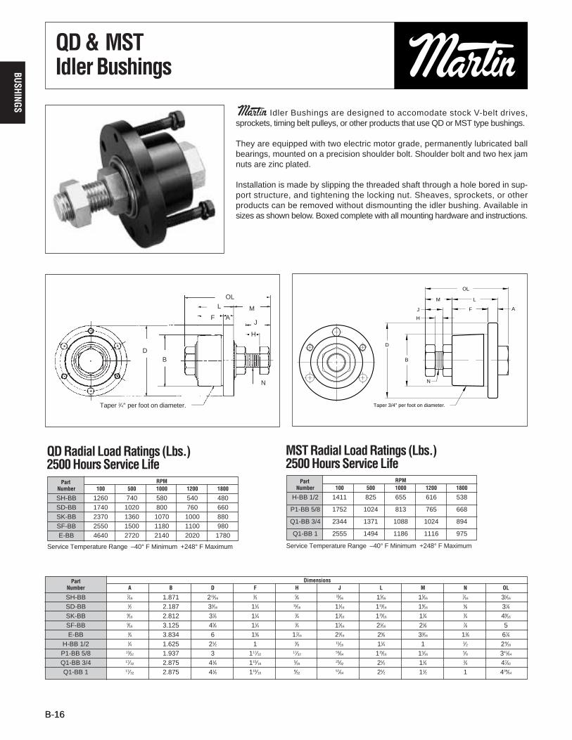
QD & MSTIdler Bushings
Martin Idler Bushings are designed to accomodate stock V-belt drives,sprockets, timing belt pulleys, or other products that use QD or MST type bushings.
They are equipped with two electric motor grade, permanently lubricated ballbearings, mounted on a precision shoulder bolt. Shoulder bolt and two hex jamnuts are zinc plated.
Installation is made by slipping the threaded shaft through a hole bored in sup-port structure, and tightening the locking nut. Sheaves, sprockets, or otherproducts can be removed without dismounting the idler bushing. Available insizes as shown below. Boxed complete with all mounting hardware and instructions.
QD Radial Load Ratings (Lbs.)2500 Hours Service Life
Service Temperature Range –40° F Minimum +248° F Maximum
SH-BB 1260 740 580 540 480SD-BB 1740 1020 800 760 660SK-BB 2370 1360 1070 1000 880SF-BB 2550 1500 1180 1100 980E-BB 4640 2720 2140 2020 1780
Part RPMNumber 100 500 1000 1200 1800
Part DimensionsNumber A B D F H J L M N OL
Taper 3⁄4″ per foot on diameter.
DB
F AM
J
H
N
LOL
N
Taper 3/4" per foot on diameter.
OL
D
B
J
H
M L
F A
MST Radial Load Ratings (Lbs.)2500 Hours Service Life
Service Temperature Range –40° F Minimum +248° F Maximum
H-BB 1/2 1411 825 655 616 538
P1-BB 5/8 1752 1024 813 765 668
Q1-BB 3/4 2344 1371 1088 1024 894
Q1-BB 1 2555 1494 1186 1116 975
Part RPMNumber 100 500 1000 1200 1800
B1-B16 3/27/03 12:18 PM Page 16