Embed Size (px)
Citation preview
1
Interconnect (1)
Lecture 818-322 Fall 2003
Textbook: [4.1-4.4.5]
[Slides on RC Trees and Elmore delay model adapted from R. Rutenbar, 18-760 “Logic To Layout”, CMU Fall 2001]
Overview
Interconnect parametersCapacitanceResistanceInductance (much later in the sequel)
Electrical wire models Lumped RC modelElmore delay
2
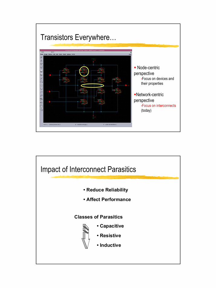
Transistors Everywhere…
Node-centric perspective
•Focus on devices and their properties
Network-centric perspective
•Focus on interconnects(today)
Impact of Interconnect Parasitics
• Reduce Reliability
• Affect Performance
Classes of Parasitics
• Capacitive
• Resistive
• Inductive
3
Why Does This Matter?
ProblemDelays on signals due to wires are no longer negligibleModern designs must meet tight timing specifications
Delay modelingSources for delayDelay comes from parasitic loading of the interconnectDepends critically on the exact shape of the wired net
Accurate prediction We’ll use a first-order model
INTERCONNECT
Dealing with Capacitance

4
Capacitance: The Parallel-Plate Model
SiO 2
Substrate
L
W >> tox
H
tox
Current flow WLC WLtεC ox
ox
ox ==
[F/m]εεε 0rox =
εr = dielectric constant (relative permitivity) = 3.9
ε0 = permitivity of the free space = 8.854·10-12 [F/m]
εox = 3.5 ·10-11 [F/m]
The Unit Transistor Capacitance
4λ
L
W2λ
2λ
5λ
λ
λ
Source Drain2λ
2λ
WLCC oxg =
]m[pF/1017)(3510200)-(100108.8543.9
tεC 24
10-
-12
ox
oxox µ−×−=
×××
==
tox = (100 – 200) 10-10 [m]λ= 0.5 µm; W = 2 µm, L = 1 µm
[fF] 5 [pF]0.0051025.52C 4g =≈××= −
5
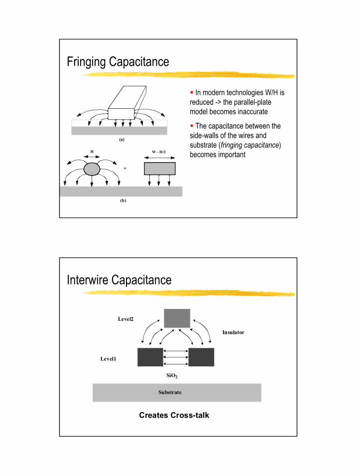
Fringing Capacitance
In modern technologies W/H is reduced -> the parallel-plate model becomes inaccurate
The capacitance between the side-walls of the wires and substrate (fringing capacitance) becomes important W - H/2H
+
(a)
(b)
Interwire Capacitance
Substrate
SiO2
Insulator
Level1
Level2
Creates Cross-talk
6
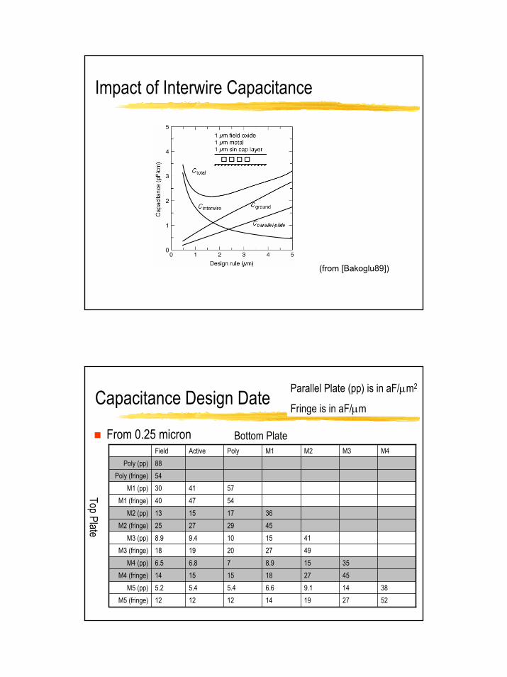
Impact of Interwire Capacitance
(from [Bakoglu89])
Capacitance Design Date
From 0.25 micron
52271914121212M5 (fringe)38149.16.65.45.45.2M5 (pp)
452718151514M4 (fringe)35158.976.86.5M4 (pp)
4927201918M3 (fringe)4115109.48.9M3 (pp)
45292725M2 (fringe)36171513M2 (pp)
544740M1 (fringe)574130M1 (pp)
54Poly (fringe)88Poly (pp)
M4M3M2M1PolyActiveField
Top Plate
Bottom Plate
Parallel Plate (pp) is in aF/µm2
Fringe is in aF/µm
7
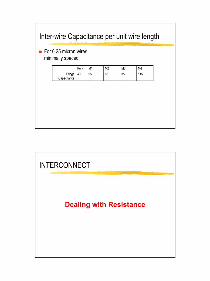
Inter-wire Capacitance per unit wire length
For 0.25 micron wires, minimally spaced
11585859540Fringe Capacitance
M4M3M2M1Poly
INTERCONNECT
Dealing with Resistance

8
Wire Resistance
W
LH
R = ρH W
L
Sheet ResistanceRo
R1 R2
Ohms Per Square
Six Squares
Three Squares
I I
L
W
9
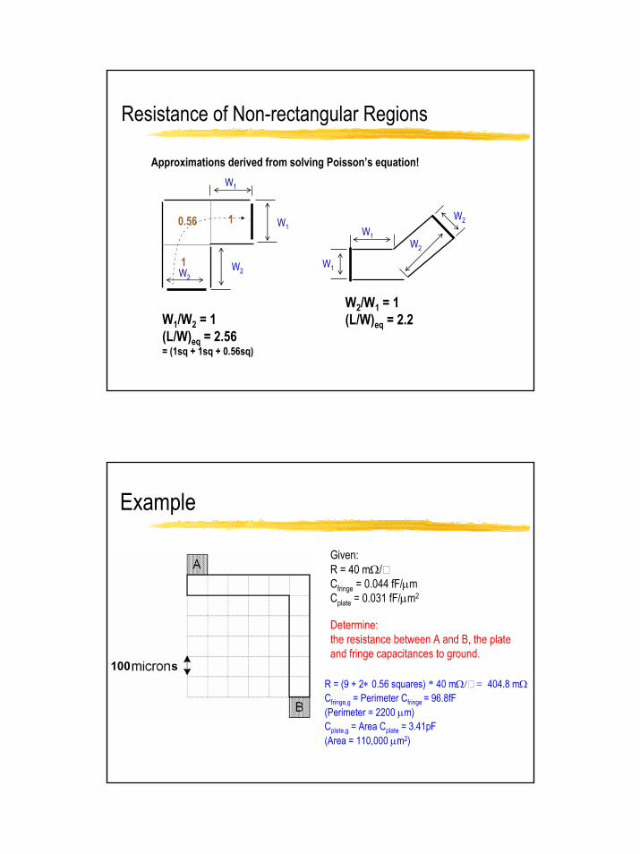
Resistance of Non-rectangular Regions
Approximations derived from solving Poisson’s equation!
W1/W2 = 1(L/W)eq = 2.56= (1sq + 1sq + 0.56sq)
1
10.56 W1
W2
W1
W2
W2/W1 = 1(L/W)eq = 2.2
W1
W1
W2
W2
Example
100 sR = (9 + 2∗ 0.56 squares) * 40 mΩ/ = 404.8 mΩCfringe,g = Perimeter Cfringe = 96.8fF (Perimeter = 2200 µm)Cplate,g = Area Cplate = 3.41pF (Area = 110,000 µm2)
Given:R = 40 mΩ/Cfringe = 0.044 fF/µmCplate = 0.031 fF/µm2
Determine: the resistance between A and B, the plate and fringe capacitances to ground.

10
Overview
Interconnect parametersCapacitanceResistance
Electrical wire models Lumped RC modelElmore delay
Interconnect Models
SiO 2
Substrate
L
W
H
tox
Current flow
11
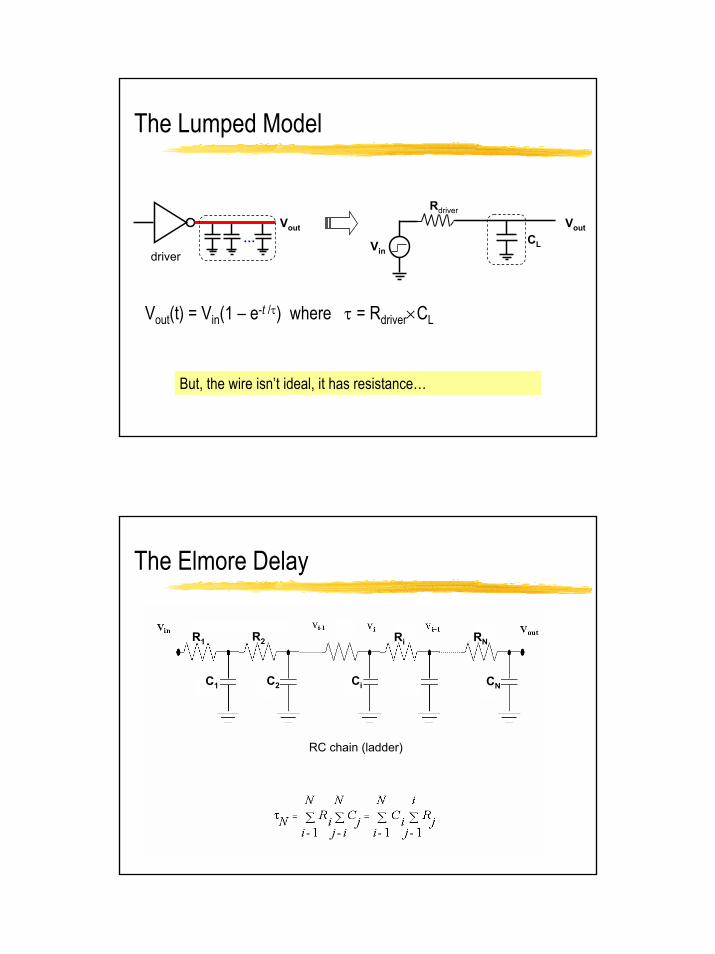
The Lumped Model
…
Rdriver
Vin
VoutVout
driverCL
Vout(t) = Vin(1 – e-t /τ) where τ = Rdriver×CL
But, the wire isn’t ideal, it has resistance…
The Elmore Delay
CNC1 C2 Ci
R1 R2 Ri RN
RC chain (ladder)

12
Lumped π Network
Vin VoutR
C
R
C
R
C…
R = Rline/N C = Cline/N
tN = N(N+1)/2 (RC) t∞ =1/2 (RlineCline)
…Vout
driver
τ = Rline(Cline/2)
This is the π model!
Rline
1/2Cline1/2Cline
RC Trees
Note: each of the Rs, Cs in this tree are probably different numbers, since each depends on the geometry of the segment
13
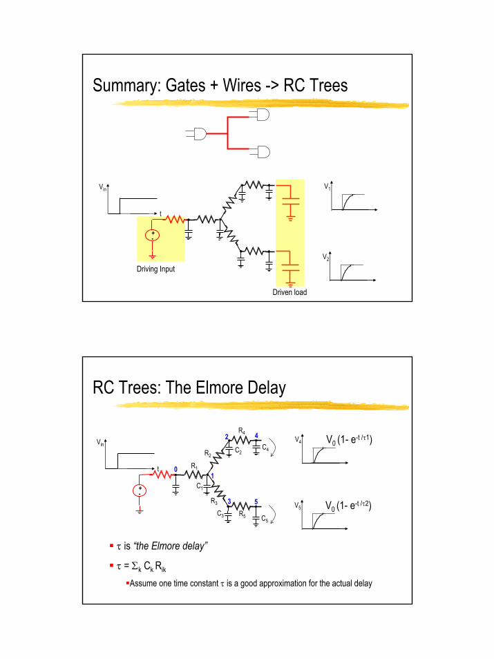
Summary: Gates + Wires -> RC Trees
Vin
t
V1
V2
+-
Driving Input
Driven load
RC Trees: The Elmore Delay
Vin
t
+-
R1
R2
R4
R3
R5
1
2
3
4
5
0
C1
C2
C3V0 (1- e-t /τ2)
V4
V5
C4
C5
V0 (1- e-t /τ1)
τ is “the Elmore delay”
τ = Σk Ck Rik
Assume one time constant τ is a good approximation for the actual delay
14
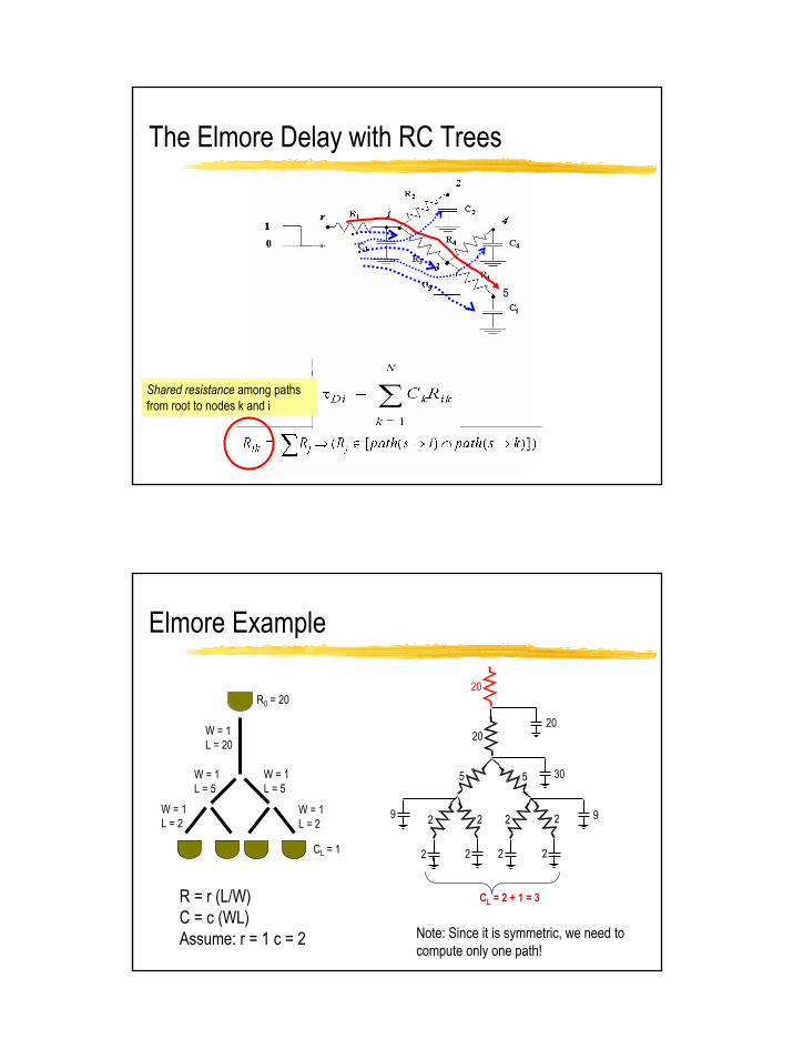
The Elmore Delay with RC Trees
Shared resistance among paths from root to nodes k and i
5
Elmore Example
W = 1L = 20
W = 1L = 5
W = 1L = 2
R = r (L/W)C = c (WL)Assume: r = 1 c = 2
20
5 5
2 2 2 2
2 2 2 2
20
30
99
R0 = 20
CL = 1
20
CL = 2 + 1 = 3
W = 1L = 5
W = 1L = 2
Note: Since it is symmetric, we need to compute only one path!

15
τleft (5681)
τright (7606)
Another Elmore Example
W = 1L = 20
W = 1L = 5
W = 1L = 2
20
5 40
2 2 2 2
3 3 3 3
20
65
449
R0 = 20
CL = 1
20
W = 1L = 40
1
2
34
5678
Another Elmore Example
W = 1L = 20
W = 1L = 5
W = 1L = 2
20
5 0.5
2 2 2 2
3 3 3 3
20
75
549
R0 = 20
CL = 1
20
W = 10L = 5
R smallerC bigger

16
Elmore Applications
clock root
Flip Flops
Elmore delay is the easiest to compute delay estimator
Fairly accurate for symmetric designs
Inaccurate for anything else
Can be used for layout optimization (e.g. clock trees)
For more accuracy, there are more sophisticated models