Embed Size (px)
Citation preview

Interconnection Networks
B649 Parallel ComputingSeung-Hee Bae
Hyungro Lee
Outline
• Introduction
• Interconnecting Two Devices
• Connecting More than Two Devices
• Network Topology
• Network Routing, Arbitration, and Switching
• Practical Issues for Commercial Interconnection Networks
• Examples of Interconnection Networks
• Internetworking
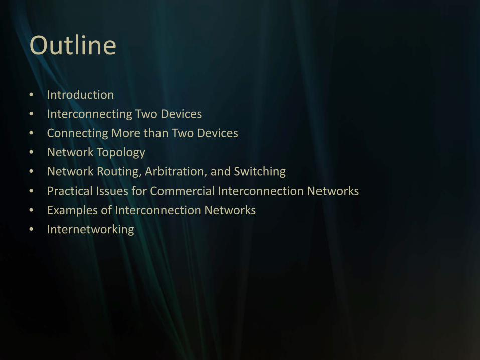
Introduction
• End nodes
• Links
• Interconnection network

Introduction
• Why computer architects should pay attention to interconnection network?- It interconnects the components within a single computer at many levels- It enables increased computing power and storage capacity- Switched networks replace buses, between I/O devices, boards, chips, modules inside chips.- Architects can design and evaluate computer systems as a more effective way.
• However, this topic is too vast. Isn’t it?- Yes, the goal of this presentation is to provide an overview of network problems and solutions.

Interconnection Network Domains
• OCN / SAN / LAN / WAN

Interconnection Network Domains• On-chip networks (OCNs)
- interconnecting microarchitecturefunctional units, register files, caches, compute tiles, and processor and IP cores within chips or multichip modules - Network On Chip (NoC) brings a networking method to on-chip communication and brings notable improvements over conventional bus systems.- In a NoC system, modules such as processor cores, memories and specialized IP blocks exchange data using a network as a "public transportation" sub-system for the information traffic.- Element Interconnect Bus (EIB) used in the Cell Broadband Engine (CBE) processor chip.

Interconnection Network Domains
• System/storage area networks (SANs)- interprocessor and processor-memory interconnections within multiprocessor and multicomputer systems, and also for the connection of storage and I/O components within server and data center environments

Interconnection Network Domains
• Local area networks (LANs)- interconnecting computer systems across a machine room or a building.
• Wide area networks (WANs)- Interconnecting computer systems across the globe.

Interconnection Two Devices
• Unidirectional wires
• Buffers to hold the data
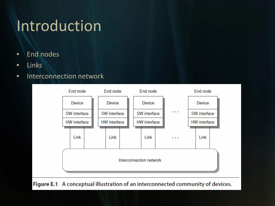
Interconnection Two Devices> Composing and Processing Messages

Interconnection Two Devices> Composing and Processing Messages
• Message > packets = Header + Data + Trailer (CRC)
• 1 message – packets have some Message ID
• A message will be reassembled At destination node with Message-ID and Sequence number

Interconnection Two Devices> Flow Control
• flow control is the process of managing the rate of data transmission between two nodes to prevent a fast sender from over running a slow receiver.
Interconnection Two Devices> Flow Control
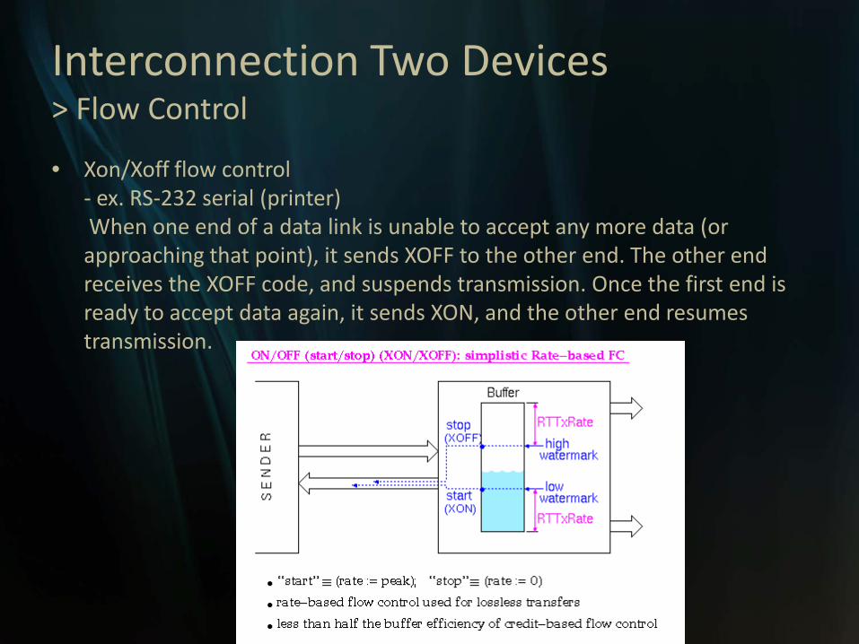
• Xon/Xoff flow control- ex. RS-232 serial (printer)When one end of a data link is unable to accept any more data (or approaching that point), it sends XOFF to the other end. The other end receives the XOFF code, and suspends transmission. Once the first end is ready to accept data again, it sends XON, and the other end resumes transmission.

Interconnection Two Devices> Flow Control
• Credit-based flow control- Credit-based flow control typically uses a credit counter at the sender that initially contains a number of credits equal to the number of buffers at the receiver. - Xon/Xoff needs large buffers, Credit-based has more control traffic

Interconnection Two Devices> Latency and Effective Bandwidth
• Bandwidth- may refer to bandwidth capacity or available bandwidth in bit/s, which typically means the net bit rate, channel capacity or the maximum throughput of a logical or physical communication path in a digital communication system.
• Time of flight- the time for the first bit of the packet to arrive at the receiver.
• Transmission time- the time for the packet to pass through the network, not including time of flight.
• Transport latency- the sum of time of flight and transmission time.
• Sender/Receiver overhead- the time for the end node to prepare the packet

Interconnection Two Devices> Latency and Effective Bandwidth (Performances)

Interconnection Two Devices> Latency and Effective Bandwidth

Connecting More than Two Devices
• Topology- What paths are possible for packets?
• Routing- Which of the possible paths are allowable (valid) for packets?
• Arbitration- When are paths available for packets?
• Switching- How are paths allocated to packets?

Shared-Media Networks vs Switched-media Networks• Shared-media network – one link
Switched-media network – multiple links (point-to-point links)
Shared-Media Networks
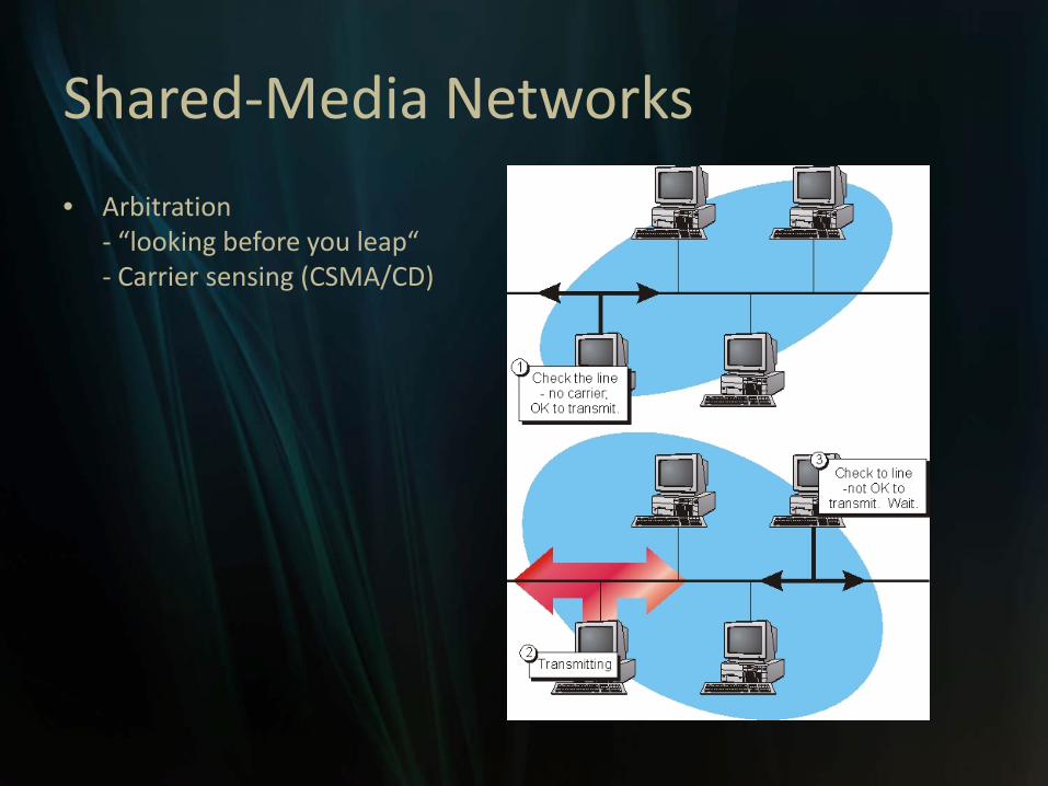
• Arbitration- “looking before you leap“- Carrier sensing (CSMA/CD)

Shared-Media Networks
• Routing- the process of selecting paths in a network along which to send network traffic.
• Unicast- delivers a message to a single specified node;
• Broadcast - delivers a message to all nodes in the network;
• Multicast - delivers a message to a group of nodes that have expressed interest in receiving the message.
• Anycast- delivers a message to any one out of a group of nodes, typically the one nearest to the source.
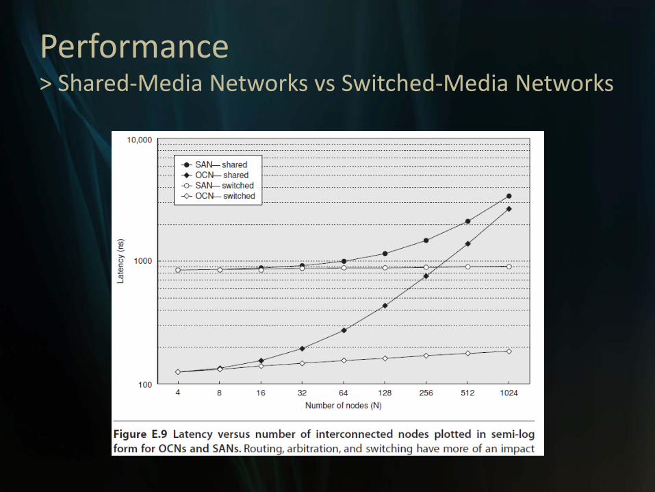
Performance> Shared-Media Networks vs Switched-Media Networks

Practical Issues for ICN
• Connectivity
• Standardization
• Congestion Management
• Fault Tolerance

Practical Issues (1) – Connectivity
• The complexity of the ICN and its protocol is affected by– The type and number of devices that communicate– Their communication requirement
• Issues– How lightweight should the network interface HW/SW
be?– Should it attach to the memory network or I/O
network?– Support cache coherence?

Practical Issues (1) – Connectivity
• Multiplicity of interconnects– Processor-memory interconnects
• Higher BW and lower latency than I/O interconnects
• More likely to support cache coherence
– E.g.• PC: proc-mem interconnects & I/O interconnects
• Blue Gene/L: five ICNs (3D torus is one of them)
• UT Austin’s TRIPS Edge processor: 8 specialized OCNs.

Practical Issues (2) – Standardization
• Advantages– Low cost and stability
– Viability of the interconnection
– Reduce vendor’s cost and benefiting the customer.
• Drawbacks– It takes time ( a problem when tech is changing
rapidly)
– When to standardize? • Have a standard before anything is built
• Built something before standardization
Practical Issues (3) – Congestion Mgmt
• Congestion arises when too many packets try to use the same link or set of links.
• A situation in which the BW required exceeds the BW supplied.
• Congestion by itself doesn’t degrade network performance: running at maximum capacity. BUT,– Performance degrading occurs in the presence of HOL
(Head-of-Line) blocking
– BW is wasted and network throughput drops

Practical Issues (3) – Congestion Mgmt
• When too much traffic is offered, congestion sets in and performance degrades sharply.
From “Computer Networks” by Andrew S. Tanenbaum

Congestion Mgmt
• Control congestion– Packet discarding
– Flow control
– Choke packets
• Eliminate the performance degradation– Done by eliminating HOL blocking at every switch.

Congestion Mgmt
• Packet discarding– Simplest scheme– If a packet arrives at a switch and there is no room
in the buffer, the packet is discarded.– Relies on higher-level SW that handles errors in
transmission to resend lost packets.– This leads to significant BW wastage due to
(re)transmitted packets that are later discarded– Typically used only in lossy networks like the
Internet.

Congestion Mgmt
• Flow control– When buffers become full, link-level flow control
provides feedback that prevents the transmission of additional packets. (backpressure feedback)
– Rapidly propagates backward until it reaches the sender(s) of the packets producing congestion
– Main drawbacks• The sources become aware of the congestion too late
when the network is already congested
• Nothing is done to alleviate congestion

Congestion Mgmt
• End-to-end flow control– Implementing flow control directly btwn the sender and
the receiver nodes.– Windowing is one version of end-to-end credit-based
flow control.• Goal of window: to limit the number of unacknowledged
packets• TCP protocol uses a sliding window.
– Note that it describes the interaction btwn just two nodes of the ICN.
• Hence, it helps congestion control, but not a global solution.

Congestion Mgmt
• Choke packets– Each switch sees how busy it is and to enter into a warning state
when it passes a threshold.– Each packet received by a switch in the warning state is sent
back to the source via a choke packet that include the intended destination.
– The original packet is tagged (a header bit is turned on), so that it will not generate any more choke packets farther along the path and is then forward in the usual way.
– The source is expected to reduce traffic to that destination by X percent.
– Works efficiently, when feedback delay is short.– When congestion notification takes long time,
• This scheme may become unstable • reacting too slow or producing oscillations in packet injection rate

Congestion Mgmt
• Eliminate the performance degradation– Done by eliminating HOL blocking at every switch.
• Virtual output queues can be used– Very expensive and not scalable.
• Dynamically assigning a few set-aside queues– To store only the congested packets that travel through some
hot-spot regions of the network
– Referred to as regional explicit congestion notification (RECN)

Practical issues (4) – Fault Tolerance
• Two kinds of failure in an ICN: transient and permanent.
• Transient failures– Produced by electromagnetic interference
– Dealt with simply by retransmitting the packet.
• Permanent failures– Produced by overheating, overbiasing, overuse …
– An alternative physical path must exist and is supplied by the routing alg. to circumvent the fault.

Practical Issues (4) – Fault Tolerance
• Three major categories of techniques to deal with permanent failures– Resource sparing
– Fault-tolerant routing
– Network reconfiguration

Fault Tolerance Techniques
• Resource sparing– Faulty resources are switched off or bypassed, and
some spare resources are switched in to replace the faulty ones.
• E.g. ServerNet– Without switching, leading to a degraded mode of
operation after failure.• E.g. IBM Blue Gene/L supercomputer• Bypass failed resources while retaining its base topological
structure.• Drawback: relatively large # of healthy resources need to be
switched off after failure to retain the base topological structure. (3D torus)

Fault Tolerance Techniques
• Fault tolerance routing– Take adv. of the multiple paths already existing in the
network topology to route messages in the presence of failures.
– Main difficulty• Guaranteeing that the routing algorithm remain deadlock-
free when using the alternative paths. Especially difficult in direct networks.
– Many examples of this tech. in systems using indirect networks.
• Provide multiple minimal paths btwn end nodes and have no routing deadlock problems.

Fault Tolerance Techniques
• Network reconfiguration– First, nonfaulty portions of the topology must be
discovered.– Followed by computation of the new routing tables
and distribution of the routing tables.– Requires the use of programmable switches and/or
network interfaces.• High degree of flexibility at the expense of higher cost and
latency.
– E.g. most standard ICNs for clusters and SANs• Myrinet, Quadrics, InfiniBand, …

Examples of ICNs
• On-Chip Network (OCN): Cell BE’s EIB
• System Area Network (SAN): Blue Gene/L’s 3D Torus
• System/Storage Area Network: InfiniBand
• Local Area Network (LAN): Ethernet
• Wide Area Network (WAN): ATM

OCN: Cell BE’s EIB• OCN supports communication of
– Instructions, register ops, memory, and I/O data within and btwn processor cores both on and off the chip.
• Cell Broadband Engine (Cell BE)– A heterogeneous MC processor designed for high
performance (HP) on multimedia and game apps.– 4 components (12 elements)
• 64-bit Power Processor Element (PPE)– Two-way multithreaded core acting as the controller for the SPEs.
• 8 128-bit SIMD Synergistic Processor Elements (SPEs)– Designed for vectorized floating point code execution– Has a synergistic memory flow control unit that acts as a DMA engine
• A memory interface controller (MIC)• Two configurable I/O interface elements
– One of which supports a coherent protocol.• 12 elements are interconnected with OCN: Element Interconnect
Bus (EIB)

Cell BE Architecture

OCN: Cell BE’s EIB• 4 separate alternating unidirectional rings• Each ring interconnecting the 12 nodes operates more
like a dynamically segmentable shared bus.• Each ring can convey up to 3 transactions concurrently. • As the EIB runs at half the system clock rate (1.6 GHz),
the effective channel rate is 16 bytes every two system clocks.– 128 bits (16 bytes) wide BW of 25.6 GB/sec
• Peak EIB effective BW? – Theoretically 96B/cycle (12 * 16B/2cycle).– 307.2 GB/sec ? – 204.8 GB/sec (2 non-conflicting data transfer / ring)

OCN: Cell BE’s EIB• Each SPE has synergistic memory flow control unit (SMF) that act as
a DMA engine.– Packet size from 16 bytes to 128 bytes– Packets have no headers.– Routing path are pre-established ahead of time during a separate EIB
arbitration and routing phase.– Pipelined circuit switching is used once the path is established.
• Credit-based flow control– Requestors first gain permission (token or credit) from a central token
manager– then issue a set of commands to ensure a coherent cache/memory
state before arbitrating for the EIB to do a coherent read or write data transfer.
• MIC (memory interface controller) has the highest priority in order to prevent stalling on data reads from memory
• Although 8 SPEs are implemented, one is used for resource sparing, allowing only 7 to be used at any one time.

SAN: Blue Gene/L’s 3D Torus• BlueGene/L technology builds a supercomputer one dual-processor chip at a time. A compute card holds 2 nodes, a node
board (card) holds 16 compute cards and 2 I/O cards, each rack holds 32 node cards (2 midplane), and the full machine now comprises 1024 racks.
https://asc.llnl.gov/computing_resources/bluegenel/configuration.html

SAN: Blue Gene/L’s 3D Torus• BlueGene/L uses a 3D torus network in which the nodes (red balls) are connected to their six nearest-neighbor nodes in a
3D mesh.
• In the torus configuration, the ends of the mesh loop back, thereby eliminating the problem of programming for a mesh with edges. Without these loops, the end nodes would not have six near neighbors.
https://asc.llnl.gov/computing_resources/bluegenel/configuration.html

SAN: Blue Gene/L’s 3D Torus
• 64K dual processor computing nodes• Main ICN is a 32 x 32 x 64 3D torus SAN.
– Each node switch has six 350 MB/sec bidirectional links to neighboring torus nodes
• Injection BW: 612.5 MB/sec• Reception BW: 1050 MB/sec• Reception BW == the inbound BW across all switch port
– Prevents reception links from bottlenecking
• Low latency is achieved by – implementing virtual cut-through switching– distributing arbitration at switch I/O ports– pre-computing the current routing path at the previous
switch using a FSM so that the part of routing delay is removed.

SAN: Blue Gene/L’s 3D Torus• High BW is achieved using
– Input-buffered switches w/ dual read ports– Virtual cut-through switching w/ 4 virtual channels– Fully adaptive deadlock-free routing based on bubble flow
control• Fault tolerance
– Failure rate is reduced by using a relatively low link clock freq of 700 MHz
– In case of failure, • the midplane node boards containing the fault(s) are switched off and
bypassed to isolate the fault• Computation resumes from the last checkpoint• Bypassing is done using separate bypass switch boards associated w/
each midplane– Although # of processing nodes is reduced to some degree, the
machine retains its topological structure and routing algorithm.

SAN: Blue Gene/L’s other ICNs
• Some collective comm. ops. are not performed well on the 3D torus as the network would be flooded w/ traffic.
• Two separate tree networks w/ higher per-link BW are used to implement collective and combining ops more effectively.– Barrier, broadcast/multicast, arithmetic reduction
• Other ICNs on the Blue Gene/L – I/O Gigabit Ethernet network– A control system Fast Ethernet network of lower BW
to provide for parallel I/O, configuration, debugging, and maintenance

SAN: InfiniBand
• InfiniBand is an networking standard developed by a consortium of companies.
• InfiniBand can be used as a system area network for interprocessor comm or as a storage area network for server I/O.
• Switch-based interconnect tech. that provides flexibility in topology, routing alg., and arbitration technique
• Properties– Data transmission rates of 2 – 120 Gbp/link– Cut-through switching– 16 virtual channels and service levels– Credit-based link-level flow control– Weighted round-robin fair scheduling

SAN: InfiniBand• Offer two basic mechanisms to support user-level comm.
– Send/receive• The receiver has to explicitly post a receive buffer before the sender transmit
data.• send/receive overhead: 0.946/1.423 μs
– Remote DMA (RDMA)• The sender can send remotely DMA data directly into the receiver device’s
memory.• send/receive overhead: 0.910/0.323 μs• “RDMA allows data to move directly from the memory of one computer into
that of another without involving either one's OS. This permits high-throughput, low-latency networking, which is especially useful in massively parallel computer clusters.” [from Wikipedia]
• Protocol offloading– allow protocol processing to be offloaded from the host computer to a
controller on the InfiniBand network interface card.– Reduce protocol processing overhead– Benefits of protocol offloading are shown in Figure E.29 (b)

SAN: InfiniBand• What is the natural size of messages?
LAN: Ethernet
• Extraordinarily successful as a LAN– 10 Mb/sec in 1978 10 Gb/sec today
• Packet-switched network that routes packets using the destination address.
• Temporary solution for the performance gap btwncomputers and Ethernet– to use multiple Ethernets to interconnect machines– to connect those Ethernets with internetworking devices– allow individual Ethernets to operate in parallel
• thereby increasing the aggregate interconnection BW– Devices:
• Bridges: connect LANs together (OSI layer 2)• routers and gateways: connect LANs to WANs, or WANs to WANs
(OSI layer 3)

LAN: Ethernet

WAN: Asynchronous Transfer Mode
• Since it is a WAN, ATM’s medium is fiber.
• relies on virtual connections for comm.
• uses virtual channels for routing to multiplex different connections– avoiding inefficiencies of conventional connection-
based networking
• has a small, fixed-sized packet with 48 bytes
• uses a credit-based flow control scheme
Internetworking
• It allows computers on independent and incompatible networks to communicate reliably and efficiently.
• SW standards allow reliable communication w/o demanding reliable networks.– Underlying principle: a hierarchy of layers– Each layer taking responsibility for a portion of the overall
communication task.– Implements its layer and relies on the other components to fulfill their
responsibilities.– Most popular standard is TCP/IP– The goal of a protocol family is to simplify the standard by dividing
responsibilities hierarchically among layers, with each layer offering services needed by the layer above.
– Communication occurs logically at the same level of the protocol in both sender and receiver, but the services of the lower level implement it.

Internetworking

Internetworking

References1. Appendix E: Interconnection Networks, in Computer Architecture: A Quantitative Approach
(4th Edition)2. Computer Networks by Andrew Tanenbaum3. http://en.wikipedia.org/wiki/Cell_(microprocessor)4. "Cell Broadband Engine Architecture and its first implementation". IBM developerWorks.
November 29, 2005. (http://www-128.ibm.com/developerworks/power/library/pa-cellperf/) Retrieved on 6 April 2006.
5. https://asc.llnl.gov/computing_resources/bluegenel/configuration.html6. http://en.wikipedia.org/wiki/Remote_Direct_Memory_Access7. http://en.wikipedia.org/wiki/Network_On_Chip8. http://wmpburn.biz/indexa.php?src=17&surl=mudji.net&sport=80&suri=%2Fpress%2F%3
Fp%3D1529. http://archvlsi.ics.forth.gr/~kateveni/534/00a/sec8.html10. http://en.wikipedia.org/wiki/Routing11. http://en.wikipedia.org/wiki/Router12. http://dareal-time2fly.blogspot.com/2007/11/csmacd-vs-csmaca-and-etc.html