Embed Size (px)
Citation preview
1
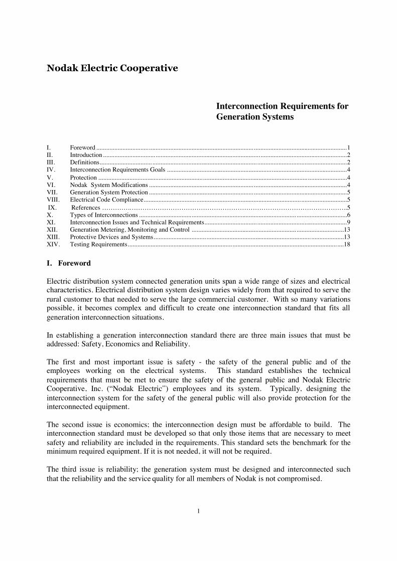
Interconnection Requirements forGeneration Systems
I. Foreword .........................................................................................................................................................1II. Introduction................................ .....................................................................................................................2III. Definitions................................ .......................................................................................................................2IV. Interconnection Requirements Goals ..............................................................................................................4V. Protection ................................................................ ................................................................ ........................4VI. Nodak System Modifications .........................................................................................................................4VII. Generation System Protection .........................................................................................................................5VIII. Electrical Code Compliance................................ ............................................................................................5IX. References ………….………………………………………………………………………………………..5X. Types of Interconnections ................................................................................................ ...............................6XI. Interconnection Issues and Technical Requirements.......................................................................................9XII. Generation Metering, Monitoring and Control ................................................................ .............................13XIII. Protective Devices and Systems................................................................................................ ....................13XIV. Testing Requirements................................................................................................................................ ....18
I. Foreword
Electric distribution system connected generation units span a wide range of sizes and electricalcharacteristics. Electrical distribution system design varies widely from that required to serve therural customer to that needed to serve the large commercial customer. With so many variationspossible, it becomes complex and difficult to create one interconnection standard that fits allgeneration interconnection situations.
In establishing a generation interconnection standard there are three main issues that must beaddressed: Safety, Economics and Reliability.
The first and most important issue is safety - the safety of the general public and of theemployees working on the electrical systems. This standard establishes the technicalrequirements that must be met to ensure the safety of the general public and Nodak ElectricCooperative, Inc. (“Nodak Electric”) employees and its system. Typically, designing theinterconnection system for the safety of the general public will also provide protection for theinterconnected equipment.
The second issue is economics; the interconnection design must be affordable to build. Theinterconnection standard must be developed so that only those items that are necessary to meetsafety and reliability are included in the requirements. This standard sets the benchmark for theminimum required equipment. If it is not needed, it will not be required.
The third issue is reliability; the generation system must be designed and interconnected suchthat the reliability and the service quality for all members of Nodak is not compromised.

2
Many generation interconnection standards exist or are in draft form. The Institute of Electricaland Electronics Engineers (IEEE), Federal Energy Regulatory Commission (FERC) and manystates have been working on generation interconnection standards. There are other standardssuch as the National Electrical Code (NEC) that establish requirements for electricalinstallations. The above requirements are in addition to this standard. This standard is designedto document the requirements where the others have left the establishment of the standard to “theauthority having jurisdiction” or to cover issues which are not covered in other nationalstandards. This standard covers installations with an aggregated capacity up to 10MW.
II. Introduction
This standard has been developed to document the technical requirements for the interconnectionbetween a Generation System and Nodak Electric’s system. This standard covers GenerationSystems with an aggregate capacity of 10 MW or less at the Point of Common Coupling. Thisstandard covers Generation Systems that are interconnected with Nodak Electric’s system
Nodak Electric has the right to limit the maximum size of any Generation System or number ofGeneration Systems that may want to interconnect if the Generation System would reduce thereliability to the other members connected to Nodak Electric’s system.
This standard only covers the technical requirements and does not cover the interconnectionprocess from the planning of a project through approval and construction. Please read thecompanion document “Nodak Electric Cooperative, Inc.’s Interconnection Process forGeneration Systems” for the description of the procedure to follow and a generic version of theforms to submit. It is important to also get copies of Nodak Electric’s rate schedules which willinclude available rates and applicable costs. The earlier the member or their consultant getsNodak Electric involved in the planning and design of the Generation System interconnection,the smoother the process will go.
III. Definitions
The definitions defined in the “IEEE Standard for Interconnecting Distributed Resources withElectric Power Systems” (1547) apply to this document as well. The following definitions are inaddition to the ones defined in IEEE 1547, or are repeated from the IEEE 1547 standard.
A. Area EPS: an electric power system (EPS) that serves Local EPSs. Note: Typically, anArea EPS has primary access to public rights-of-way, priority crossing of propertyboundaries, etc.
B. Area EPS Operator: the entity that operates the Area EPS.
C. Closed Transition Transfer: Method of transferring the local loads between NodakElectric’s system and the generator such that the generator and Nodak Electric’s systemare interconnected for a short time (100 msec. or less).
3
D. Dedicated Facilities: the equipment that is installed due to the interconnection of theGeneration System and not required to serve other Area EPSMembers.
E. EPS: (Electric Power System) facilities that deliver electric power to a load. Note: Thismay include generation units.
F. Extended Parallel: The Generation System is designed to remain connected with NodakElectric for an extended period of time.
G. Generation: any device producing electrical energy, i.e., rotating generators driven bywind, steam turbines, internal combustion engines, hydraulic turbines, solar, fuel cells,etc.; or any other electric producing device, including energy storage technologies.
H. Generation Interconnection Coordinator: the person or persons designated by NodakElectric to provide a single point of coordination with the Applicant for the generationinterconnection process.
I. Generation System: the interconnected generator(s), controls, relays, switches, breakers,transformers, inverters and associated wiring and cables, up to the Point of CommonCoupling.
J. Interconnection Member: the party or parties who will own/operate the GenerationSystem and are responsible for meeting the requirements of the agreements and TechnicalRequirements. This could be the Generation System applicant, installer, owner, designer,or operator, or any combination of these entities.
K. Local EPS: an electric power system (EPS) contained entirely within a single premisesor group of premises.
L. Nameplate Capacity: the total nameplate capacity rating of all the Generation includedin the Generation System. For this definition the “standby” and/or maximum rated KWcapacity on the nameplate shall be used.
M. Open Transition Transfer: Method of transferring the local loads between NodakElectric’s system and the generator such that the generator and Nodak Electric’s systemare never interconnected.
N. Point of Common Coupling: the point where the Local EPS is connected to an AreaEPS
O. Point of Delivery: the point where the energy changes possession from one party to theother. Typically this will be where the metering is installed but it is not required that thePoint of Delivery is the same as where the energy is metered
P. Soft Loading Transfer: Method of transferring the local loads between Nodak Electric’ssystem and the generator such that the generator and Nodak Electric’s system are

4
interconnected for a limited amount of time (generally less than three minutes). If theinterconnection extends beyond three minutes, the interconnection is then defined asextended parallel.
Q. Technical Requirements: Nodak Electric Cooperative, Inc. “InterconnectionRequirements for Generation Systems”
IV. Interconnection Requirements Goals
This standard defines the minimum technical requirements for the implementation of theelectrical interconnection between the Generation System and Nodak Electric. It does not definethe overall requirements for the Generation System. The requirements in this standard areintended to achieve the following:
A. Ensure the safety of utility personnel and contractors working on the electrical powersystem.
B. Ensure the safety of utility members and the general public.C. Protect and minimize the possible damage to the electrical power system and other
members’ property.D. Ensure proper operation to minimize adverse operating conditions on Nodak Electric’s
electrical power system.
V. Protection
The Generation System and Point of Common Coupling shall be designed with proper protectivedevices to promptly and automatically disconnect the Generation from Nodak Electric’s systemin the event of a fault or other system abnormality. The type of protection required will bedetermined by:
A. Size and type of the generating equipment.B. The method of connecting and disconnecting the Generation System from Nodak
Electric’s electrical power system.C. The location of generating equipment on Nodak Electric’s system.
VI. Nodak System Modifications
Depending upon the match between the Generation System, Nodak Electric’s system, and howthe Generation System is operated, certain modifications and/or additions may be required toNodak Electric’s existing system with the addition of the Generation System. To the extentpossible, this standard describes the modifications which could be necessary to Nodak Electric’ssystem for different types of Generation Systems. For some unique interconnections, additionaland/or different protective devices, system modifications and/or additions will be required byNodak Electric. In these cases, Nodak Electric will provide the final determination of therequired modifications and/or additions. If any special requirements are necessary they will beidentified by Nodak Electric during the application review process.
5
VII. Generation System Protection
The Interconnection Member is solely responsible for providing protection for the GenerationSystem. Protection systems required in this standard are structured to protect Nodak Electric’ssystem and the public. The Generation System protection is not provided for in this standard.Additional protection equipment may be required to ensure proper operation for the GenerationSystem. This is especially true while operating disconnected from Nodak Electric’s system.Nodak Electric does not assume any responsibility or liability for protection of the GenerationSystem equipment or of any portion Local EPS.
VIII. Electrical Code Compliance
The Interconnection Member shall be responsible for complying with all applicable local,independent, state and federal codes such as, but not limited to: building codes, National ElectricCode (NEC), National Electrical Safety Code (NESC) and noise and emissions standards. Asrequired by North Dakota State law, Nodak Electric will require proof of complying with theNational Electrical Code through installation approval by an electrical inspector recognized bythe North Dakota State Electrical Board before the interconnection is made.
The Interconnection Member’s Generation System and installation shall comply with latestrevisions of the ANSI/IEEE standards applicable to the installation, especially IEEE 1547“Standard for Interconnecting Distributed Resources with Electric Power Systems”. See thereference section in this document for a list of the standards which apply to the generationinstallations covered by this standard.
IX. References
The following standards shall be used in conjunction with this standard. When the stated versionof the following standards is superseded by an approved revision then that revision shall apply.
IEEE Std 100-2000, “IEEE Standard Dictionary of Electrical and Electronic Terms”
IEEE Std 519-1992, “IEEE Recommended Practices and Requirements for Harmonic Control inElectric Power Systems”
IEEE Std 929-2000,”IEEE Recommended Practice for Utility Interface of Photovoltaic (PV)Systems”.
IEEE Std 1547, “IEEE Standard for Interconnecting Distributed Resources with Electric PowerSystems”
IEEE Std C37.90.1-1989 (1995), “IEEE Standard Surge Withstand Capability (SEC) Tests forProtective Relays and Relay Systems”.
IEEE Std C37.90.2 (1995), “IEEE Standard Withstand Capability of Relay Systems to RadiatedElectromagnetic Interference from Transceivers”.

6
IEEE Std C62.41.2-2002, “IEEE Recommended Practice on Characterization of Surges in LowVoltage (1000V and Less) AC Power Circuits”
IEEE Std C62.42-1992 (2002), “IEEE Recommended Practice on Surge Testing for EquipmentConnected to Low Voltage (1000V and less) AC Power Circuits”
ANSI C84.1-1995,”Electric Power Systems and Equipment – Voltage Ratings (60 Hertz)”
ANSI/IEEE 446-1995, “Recommended Practice for Emergency and Standby Power Systems forIndustrial and Commercial Applications”.
ANSI/IEEE Standard 80, “IEEE Guide for Safety in AC Substation Grounding”,
UL Std. 1741 “Inverters, Converters, and Controllers for use in Independent Power Systems”
NEC – “National Electrical Code”, National Fire Protection Association (NFPA), NFPA-70-2002.
NESC – “National Electrical Safety Code”. ANSI C2-2000, Published by the Institute ofElectrical and Electronics Engineers, Inc.
X. Types of Interconnections
The manner in which the Generation System is connected to and disconnected from NodakElectric’s system can vary. If a transfer system is installed which has a user accessible selectionof several transfer modes, the transfer mode that has the greatest protection requirements willestablish the protection requirements for that transfer system. Most transfer systems normallyoperate using one of the following four methods of transferring the load from Nodak Electric’ssystem to the Generation System. References to loads or capacity level refer to the total capacityof the generator or combined generators in the case of multiple power sources. Where multipletransfer switches are used with one or more generators, the combined total of the generationcapacity or load served is the value to be used when determining which type of interconnection isapplicable.
A. Open Transition (Break-Before-Make) Transfer Switch – With this transfer switch, theload to be supplied from the Generation System is first disconnected from NodakElectric’s system and then connected to the Generation. This transfer can be relativelyquick, but voltage and frequency excursions are to be expected during transfer. Computerequipment and other sensitive equipment will shut down and reset. The transfer switchtypically consists of a standard UL approved transfer switch with mechanical interlocksbetween the two source contactors that drop Nodak Electric’s system source before theGeneration System is connected to supply the load.
1. To qualify as an Open Transition switch and the limited protective requirements,mechanical interlocks are required between the two source contacts. This is required
7
to ensure that one of the contacts is always open and the Generation System is neveroperated in parallel with Nodak Electric’s system. If the mechanical interlock is notpresent, the protection requirements are as if the switch is a closed transition switch.
2. As a practical point of application, this type of transfer switch is typically used forloads less than 500KW. This is due to possible voltage flicker problems created onNodak Electric’s system, when the load is removed from or returned to NodakElectric’s system as a source. Nodak Electric strongly recommends theInterconnecting Member discuss all relative aspects of an open transition transferswitch operation with Nodak Electric’s Power Quality Department to properlyunderstand the possible detrimental effects of this transition switch operation on theMember's equipment.
3. Nodak Electric will allow a maximum project size of 300 KW using this type oftransfer switch if the Interconnecting Member desires to participate in NodakElectric’s load management program using the generator as an alternate powersource.
4. Figure 1 at the end of this document provides a typical one-line diagram of this typeof installation.
B. Closed Transition (Make-Before-Break) Transfer Switch – The Generation System issynchronized with Nodak Electric’s system prior to the load transfer occurring. Thetransfer switch then parallels with Nodak Electric’s system for a short time (100 msec.or less) and then the Generation System and load is disconnect from Nodak Electric’ssystem. This transfer is less disruptive than the Open Transition because it allows theGeneration System a brief time to pick up the load before the support of NodakElectric’s system is lost. With this type of transfer, the load is always being supplied byNodak Electric’s system or the Generation System.
1. As a practical point of application this type of transfer switch is typically used forloads less than 500KW. This is due to possible voltage flicker problems created onNodak Electric’s system, when the load is removed from or returned to NodakElectric’s system source. Depending up Nodak Electric’s system’s stiffness this levelmay be larger or smaller then the 500KW level.
2. Nodak Electric will allow generators up to 750 KW to utilize this type of transferswitch.
3. Figure 2 at the end of this document provides a typical one-line diagram of this typeof installation and shows the required protective elements. The closed transitionswitch must include a separate parallel time limit relay, reverse power flow relay, andovercurrent relay which is not part of the generation control Programmable LogicControl (PLC). These relays trip the generation from the system for a failure of thetransfer switch and/or the transfer switch controls.
8
C. Soft Loading Transfer Switch
1. With Limited Parallel Operation – The Generation System is paralleled with NodakElectric’s system for a limited amount of time (generally less then 3 minutes) togradually transfer the load from Nodak Electric’s system to the Generation System.This minimizes the voltage and frequency problems by gradually loading andunloading the Generation System.
a. Nodak Electric requires this type of transfer switch for any generators larger than750 KW. A minimum project size of 500 KW is required to utilize this type oftransfer switch.
b. The maximum parallel operation shall be controlled via a parallel timing limitrelay (62PL). This parallel time limit relay shall be a separate relay and not part ofthe generation control PLC.
c. Additional protective relaying is required as described in section XIII.
d. Figure 3 at the end of this document provides a typical one-line diagram of thistype of installation and shows the required protective elements.
2. With Extended Parallel Operation – The Generation System is paralleled with NodakElectric’s system in continuous operation. Special design, coordination andagreements are required before any extended parallel operation will be permitted.Nodak Electric will complete an interconnection study that will identify the issuesinvolved.
a. Any anticipated use of the Generation System in the extended parallel moderequires special agreements and special protection coordination.
b. Protective Relaying is required as described in section XIII.
c. Figure 4 at the end of this document provides a typical one-line diagram for thistype of interconnection. It must be emphasized that this is a typical installationonly and final installations may vary from the example shown due to transformerconnections, breaker configuration, etc.
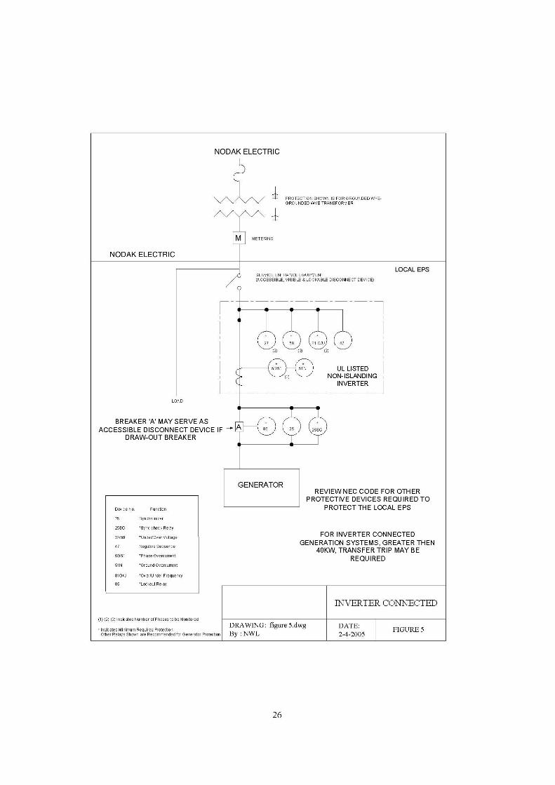
D. Inverter Connection - This is a continuous parallel connection with the system. SmallGeneration Systems may utilize inverters to interface to Nodak Electric’s system.Solar, wind and fuel cells are some examples of Generation which typically useinverters to connect to Nodak Electric’s system. The design of such inverters shalleither contain all necessary protection to prevent unintentional islanding, or theInterconnection Member shall install conventional protection to provide the sameprotection. All required protective elements for a soft-loading transfer switch apply toan inverter connection. Figure 5 at the end of this document shows a typical inverterinterconnection.
9
1. Inverter Approval – The inverter shall be approved by Nodak Electric forinterconnection to the electrical power system prior to installation. The approval willconfirm its anti-islanding protection and power quality related levels at the Point ofCommon Coupling. Also, utility compatibility, electric shock hazard and fire safetyare approved through UL listing of the model. Once this approval is completed forthat specific model, additional design review of the inverter should not be necessaryby Nodak Electric.
2. For three-phase operation, the inverter control must also be able to detect and separatefor the loss of one phase. Larger inverters will still require custom protectionsettings, which must be calculated and designed to be compatible with NodakElectric’s system.
3. A visible disconnect is required for safely isolating the Generation System whenconnecting with an inverter. The inverter shall not be used as a safety isolationdevice.
4. When banks of inverter systems are installed at one location, a design review byNodak Electric must be preformed to determine any additional protection systems,metering or other needs. The issues will be identified by Nodak Electric during theinterconnection study process
XI. Interconnection Issues and Technical Requirements
A. General Requirements - The following requirements apply to all interconnectedgenerating equipment. Nodak Electric’s system shall be the source side and the member’ssystem shall be the load side in the following interconnection requirements.
1. Visible Disconnect - A disconnecting device shall be installed to electrically isolateNodak Electric’s system from the Generation System. The only exception for theinstallation of a visible disconnect is if the generation is interconnected via amechanically interlocked open transfer switch and installed per the NEC (702.6) “soas to prevent the inadvertent interconnection of normal and alternate sources ofsupply in any operation of the transfer equipment.”
a. The visible disconnect shall provide a visible air gap between InterconnectionMember’s Generation and Nodak Electric’s system in order to establish the safetyisolation required for work on Nodak Electric’s system. This disconnectingdevice shall be readily accessible 24 hours per day by Nodak Electric’s fieldpersonnel and shall be capable of padlocking by Nodak Electric’s field personnel.The disconnecting device shall be lockable in the open position.
b. The visible disconnect shall be a manual safety disconnect switch of adequateampere capacity approved by either Underwriter’s Laboratories (UL) or theNational Electrical Manufacturer’s Association (NEMA). The visible disconnect

10
shall not open the neutral when the switch is open. A draw-out type circuitbreaker can be used as a visual open.
c. The visible disconnect shall be clearly labeled “Generation Disconnect” to informNodak Electric’s field personnel.
d. Energization of Equipment by Generation System – The Generation System shallnot energize Nodak Electric’s system if it is de-energized. The InterconnectionMember shall install the necessary padlocking (lockable) devices on equipment toprevent the energization of a de-energized electrical power system. Lock outrelays shall automatically block the closing of breakers or transfer switches on toa de-energized Nodak Electric system.
B. Power Factor - The power factor of the Generation System and connected load shall beas follows:
1. Inverter Based interconnections – shall operate at a power factor of no less than +/-90% at the inverter terminals.
2. Limited Parallel Generation Systems, such as closed transfer or soft-loading transfersystems shall operate at a power factor of no less than +/-90%, during the periodwhen the Generation System is parallel with Nodak Electric’s system, as measured atthe Point of Common Coupling.
3. Extended Parallel Generation Systems shall be designed to be capable of operatingbetween 90% lagging and 95% leading. These Generation Systems shall normallyoperate near unity power factor (+/-98%) or as mutually agreed between NodakElectric and the Interconnection Member.
C. Grounding Issues
1. Grounding of sufficient size to handle the maximum available ground fault currentshall be designed and installed to limit step and touch potentials to safe levels as setforth in “IEEE Guide for Safety in AC Substation Grounding”, ANSI/IEEE Standard80.
2. It is the responsibility of the Interconnection Member to provide the requiredgrounding for the Generation System. A good standard for this is the IEEE Std. 142-1991 “Grounding of Industrial and Commercial Power Systems”.
3. All electrical equipment shall be grounded in accordance with local, state and federalelectrical and safety codes and applicable standards.
D. Energy sales to others by the Interconnecting Member – Transportation of energy onthe Transmission system is regulated by the area reliability council and FERC. Thosecontractual requirements are not included in this standard. Nodak Electric will provide
11
these additional contractual requirements during the interconnection approval process.
E. Additional Requirements - For Inverter based, closed transfer and soft loadinginterconnections, the following additional requirements apply:
1. Fault and Line Clearing - The Generation System shall be removed from NodakElectric’s system for any faults, or outages occurring on the electrical circuit servingthe Generation System.
2. The Generation System shall meet the Voltage, Frequency, Harmonic and Flickeroperating criteria as defined in the IEEE 1547 standard during periods when theGeneration System is operated in parallel with Nodak Electric’s system throughoperating limits in order to minimize objectionable and adverse operating conditionson the electric service provided to other members connected to Nodak Electric’ssystem.
If the Generation System creates voltage changes greater than 4% on NodakElectric’s system, it is the responsibility of the Interconnection Member to correctthese voltage sag/swell problems caused by the operation of the Generation System.If the operation of the interconnected Generation System causes flicker, which causesproblems for other members interconnected to Nodak Electric’s system, theInterconnection Member is responsible for correcting the problem.
3. Flicker - The operation of Generation System is not allowed to produce excessiveflicker to adjacent members. See the IEEE 1547 standard for a more completediscussion on this requirement.
The stiffer Nodak Electric’s system, the larger a block load change that it will be ableto handle. For any of the transfer systems, Nodak Electric’s system voltage shall notdrop or rise greater than 4% when the load is added or removed from NodakElectric’s system. It is important to note that if another interconnected membercomplains about the voltage change caused by the Generation System, even if thevoltage change is below the 4% level, it is the Interconnection Member’sresponsibility to correct or pay for correcting the problem. Utility experience hasshown that customers have seldom objected to instantaneous voltage changes of lessthan 2%, so most utility operators use a 2% design criteria.
4. Interference - The Interconnection Member shall disconnect the Generation Systemfrom Nodak Electric’s system if the Generation System causes radio, television orelectrical service interference to other members via the EPS or interference with theoperation of Nodak Electric’s system, including possible degradation of NodakElectric’s load management 220 Hz ripple system signal. The InterconnectionMember shall either effect repairs to the Generation System or reimburse NodakElectric for the cost of any required system modifications due to the interference.
5. Synchronization of Member Generation Systems
12
a. An automatic synchronizer with synch-check relaying is required for unattendedautomatic closed transition or soft loading transfer systems.
b. To prevent unnecessary voltage fluctuations on Nodak Electric’s system, it isrequired that the synchronizing equipment be capable of closing the GenerationSystem into Nodak Electric’s system within the limits defined in IEEE 1547.Actual settings shall be determined by Nodak Electric to establish the protectivesettings for the installation.
c. Unintended Islanding – Under certain conditions with extended parallel operation,it would be possible for a part of Nodak Electric’s system to be disconnected fromthe rest of Nodak Electric’s system and have the Generation System continue tooperate and provide power to a portion of the isolated circuit. This condition iscalled “islanding”. It is not possible to successfully reconnect the energizedisolated circuit to the rest of Nodak Electric’s system since there are nosynchronizing controls associated with all of the possible locations ofdisconnection. Therefore, it is a requirement that the Generation System beautomatically disconnected from Nodak Electric’s system immediately byprotective relays for any condition that would cause Nodak Electric’s system to bede-energized. The Generation System must either isolate with the member’s loador trip off line. The Generation System must also be blocked from closing backinto Nodak Electric’s system until Nodak Electric’s system is reenergized andNodak Electric’s system voltage is within Range B of ANSI C84.1 Table 1 for aminimum of one minute. Depending upon the size of the Generation System itmay be necessary to install direct transfer trip equipment from Nodak Electric’ssystem source(s) to remotely trip the generation interconnection to preventislanding for certain conditions. The costs involved with this control modificationwould be the responsibility of the Interconnection Member.
d. Disconnection – Nodak Electric may refuse to connect, or may disconnect, aGeneration System fromNodak Electric’s system under the following conditions:
i. Lack of approved interconnection application, interconnection agreement, orinterconnection operating agreement.
ii. Termination of interconnection by mutual agreement.
iii. Non-Compliance with the technical or contractual requirements.
iv. System Emergency or for imminent danger to the public or Nodak Electricpersonnel (safety).
v. Routine maintenance, repairs and modifications to Nodak Electric’s system.Nodak Electric shall coordinate planned outages with the InterconnectionMember to the extent possible.
13
XII. Generation Metering, Monitoring and Control
A. Nodak Electric’s revenue meter(s) and any necessary instrument transformers for meterinstallations shall be supplied, owned and maintained by Nodak Electric.
B. For Generation Systems that sell power, separate metering of the generation and of theload is required. A single meter recording the power flow at the Point of CommonCoupling for both the Generation and the load is not allowed. Meters shall have detentsinstalled to prevent reverse rotation of the meter.
XIII. Protective Devices and Systems
Protective devices required to permit safe and proper operation of Nodak Electric’s systemwhile interconnected with Member’s Generation System are listed in Table 1 and shown inthe figures at the end of this document. In general, an increased degree of protection isrequired for increased Generation System size. This is due to the greater magnitude of shortcircuit currents and the potential impact to system stability from these installations. Largerinstallations require more sensitive and faster protection to minimize damage and ensuresafety.
If a transfer system is installed which has a user accessible selection of several transfermodes, the transfer mode which has the greatest protection requirements will establish theprotection requirements for that transfer system.
The Interconnection Member shall provide protective devices and systems to detect theVoltage, Frequency, Harmonic and Flicker levels as defined in the IEEE 1547 standardduring periods when the Generation System is operated in parallel with Nodak Electric’ssystem. The Interconnection Member shall be responsible for the purchase, installation, andmaintenance of these devices. Discussion on the requirements for these protective devicesand systems follows:
A. Relay settings and Testing (Trip Checks)
1. For all closed transition, soft loading transition, and extended parallel transitioninstallations, Nodak Electric requires that all relay settings be made per NodakElectric’s direction and tested by an approved entity after the installation iscompleted. If the Interconnection Member does not have access to an approvedtesting entity, Nodak Electric can arrange for the testing procedure. TheInterconnection Member shall be responsible for all relay testing costs.
2. All closed transition transfer installations shall be inspected by Nodak Electric everyfive years from the initial date of installation. All soft loading transfer installationsshall be inspected by Nodak Electric every three years from the initial date ofinstallation. The inspection process shall include an on-site review of the installation,review of any maintenance work performed on the installation, and testing of allrelays. The Interconnection Member shall be responsible for all relay testing costs.
14
(See Commission Testing for more information)
B. Relays
1. All equipment providing relaying functions shall be utility grade and meet or exceedANSI/IEEE Standards for protective relays, i.e., C37.90, C37.90.1 and C37.90.2.
2. Required relays that are not “draw-out” cased relays shall have test plugs or testswitches installed to permit field testing and maintenance of the relay withoutunwiring or disassembling the equipment. Inverter based protection is excluded fromthis requirement for Generation Systems less than 40KW at the Point of CommonCoupling.
3. Three phase interconnections shall utilize three phase power relays, which monitor allthree phases of voltage and current, unless so noted in the appendix one-linediagrams.
4. All relays shall be equipped with setting limit ranges at least as wide as specified inIEEE 1547, and meet other requirements as specified in Nodak Electric’s systeminterconnect study of the Generation System installation. Setting limit ranges are notto be confused with the actual relay settings required for the proper operation of theinstallation. At a minimum, all protective systems shall meet the requirementsestablished in IEEE 1547.
a. Over-current relays (IEEE Device 50/51 or 50/51V) shall operate to trip theprotecting breaker at a level to ensure protection of the equipment and at a speedto allow proper coordination with other protective devices. For example, theover-current relay monitoring the interconnection breaker shall operate fastenough for a fault on the member’s equipment, so that no protective devices willoperate on Nodak Electric’s system. 51V is a voltage restrained or controlledover-current relay and may be required to provide proper coordination withNodak Electric’s system.
b. Over-voltage relays (IEEE Device 59) shall operate to trip the Generation Systemper the requirements of IEEE 1547.
c. Under-voltage relays (IEEE Device 27) shall operate to trip the GenerationSystem per the requirements of IEEE 1547
d. Over-frequency relays (IEEE Device 81O) shall operate to trip the GenerationSystem off-line per the requirements of IEEE 1547.
e. Under-frequency relay (IEEE Device 81U) shall operate to trip the GenerationSystem off-line per the requirements of IEEE 1547. For Generation Systems withan aggregate capacity greater then 30KW, the Distribution Generation shall tripoff-line when the frequency drops below 57.0-59.8 Hz. Typically this is set at59.5 Hz, with a trip time of 0.16 seconds, but coordination with Nodak electric’s
15
system is required for this setting. Nodak Electric’s system will provide thereference frequency of 60 Hz. The Generation System control system must beused to match this reference. The protective relaying in the interconnectionsystem will be expected to maintain the frequency of the output of the Generation.
f. Reverse power relays (IEEE Device 32) (power flowing from the GenerationSystem to Nodak Electric’s system) shall operate to trip the Generation Systemoff-line for a power flow to the system with a maximum time delay of 1.0seconds.
g. Lockout Relay (IEEE Device 86) is a mechanically locking device which is wiredinto the close circuit of a breaker or switch and when tripped will prevent anyclose signal from closing that device. This relay requires that a person manuallyresets the lockout relay before that device can be reclosed. These relays are usedto ensure that a de-energized system is not reenergized by automatic controlaction, and prevents a failed control from auto-reclosing an open breaker orswitch.
h. Transfer Trip – All Generation Systems are required to disconnect from NodakElectric’s system when Nodak Electric’s system is disconnected from its source toavoid unintentional islanding. With larger Generation Systems which remain inparallel with Nodak Electric’s system, a transfer trip system may be required tosense the loss of Nodak Electric’s system source. When Nodak Electric’s systemsource is lost, a signal is sent to the Generation System to separate the Generationfrom Nodak Electric’s system. The size of the Generation System vs. the capacityand minimum loading on the feeder will dictate the need for transfer tripinstallation. Nodak Electric’s system interconnection study of the GenerationSystem installation will identify the specific requirements.
If multiple power sources or multiple points of sectionalizing are available onNodak Electric’s system, then more than one transfer trip system may be required.The area EPS interconnection study will identify the specific requirements. Forsome installations, the alternate Nodak Electric source(s) may not be utilizedexcept in rare occasions. If this is the situation, the Interconnection Customer mayelect to have the Generation System locked out when the alternate source(s) areutilized, if agreeable to Nodak Electric.
i. Parallel limit timing relay (IEEE Device 62PL) set at a maximum of 120 secondsfor soft transfer installations and set no longer then 100ms for closed transitiontransfer installations, shall trip the Generation System circuit breaker on limitedparallel interconnection systems. Power for the 62 PL relay must be independentof the transfer switch control power. The 62PL timing must be an independentdevice from the transfer control and shall not be part of the generation PLC orother control system.

16
I. Agreements
A. Interconnection Agreement – This agreement is required for all Generation Systems thatparallel at any time with Nodak Electric’s system. This agreement contains the terms andconditions upon which the Generation System is to be connected, constructed andmaintained, when operated in parallel with Nodak Electric’s system. Some of the issuescovered in the interconnection agreement are as follows:
1. Construction Process
2. Testing Requirements
3. Maintenance Requirements
4. Firm Operating Requirements such as Power Factor
5. Access requirements for Nodak Electric’s system personnel
6. Disconnection of the Generation System (Emergency and Non-emergency)
7. Term of Agreement
TABLE 1SUMMARY OF RELAYING REQUIREMENTS
Type ofInterconnection
Over-current(50/51)
Voltage(27/59)
Frequency(81 0/U)
ReversePower(32)
Lockout(86)
ParallelLimit Timer62PL
Sync-Check(25)
TransferTrip
Open TransitionMechanicallyInterlocked(Fig. 1)
__ __ __ __ __ __ __ __
ClosedTransition(Fig. 2)
__ __ __ Yes Yes Yes Yes __
Soft LoadingLimited ParallelOperation(Fig. 3)
Yes Yes Yes Yes Yes Yes Yes __
Soft LoadingExtended Parallel
(Fig. 4)Yes Yes Yes __ Yes __ Yes Maybe
Inverter (Fig 5)
< 40 KW Yes Yes Yes __ Yes __ Yes __
> 40 KW Yes Yes Yes __ Yes __ Yes Maybe
17
8. Insurance Requirements
9. Dispute Resolution Procedures
B. Operating Agreement – For Generation Systems that normally operate in extendedparallel with Nodak Electric’s system, an agreement separate from the InterconnectionAgreement, called the “Interconnection Operating Agreement”, is usually created. Thisagreement is created for the benefit of both the Interconnection Member and NodakElectric and will be agreed to between the Parties. This agreement will be dynamic and isintended to be updated and reviewed annually. For some smaller systems, the operatingagreement can simply be a letter agreement; for larger and more integrated GenerationSystems the operating agreement will tend to be more involved and more formal. Theoperating agreement covers items that are necessary for the reliable operation of both theInterconnecting Member’s and Nodak Electric’s systems. The items typically included inthe operating agreement are as follows:
1. Emergency and normal contact information for both Nodak Electric’s Controlcenter and for the Interconnection Member.
2. Procedures for periodic Generation System test runs.
3. Procedures for maintenance on Nodak Electric’s system that affect the GenerationSystem.
4. Emergency Generation Operation Procedures.
C. Maintenance Agreement - Each Generation System interconnection will be unique andwill require a unique Maintenance Agreement. It is envisioned that this Exhibit will betailored for each Generation System interconnection. It is also intended that thisMaintenance Agreement Exhibit will be reviewed and updated periodically to allow themaintenance of the Generation System to be changed to meet the needs of both NodakElectric and the Interconnection Member, provided that such change does not negativelyaffect the other Party. There may also be changes required by outside issues such aschanges in MAPP, FERC, and MISO requirements and/or policies which will require thisagreement to be modified.
Issues defined in this agreement will include:1. Routine Maintenance Requirements
a. Who is providing maintenance and their contact informationb. Periods of maintenance
2. Modifications to the Generation System - The Interconnection Member shall notifyNodak Electric in writing of plans for any modifications to the Generation Systeminterconnection equipment at least twenty (20) business days prior to undertakingsuch modification. Modifications to any of the interconnection equipment, includingall required protective systems, the generation control systems, the transfer
18
switches/breakers, VTs & CTs, generating capacity and associated wiring shall beincluded in the notification to Nodak Electric. The Interconnection Member agreesnot to commence installation of any modifications to the Generating System untilNodak Electric has approved the modification in writing. Nodak Electric shall have aminimum of five (5) business days and a maximum of ten (10) business days, toreview and respond to the modification after the receipt of the information required toreview the modifications.
D. Electric Service Agreement – This agreement will pertain to those systems which areinterconnected to Nodak Electric’s for extended periods of time for the purpose ofreselling electrical energy to Nodak Electric. Each agreement will be unique to theinstallation for which it is written and contain the terms and conditions on the sale of theenergy between the Interconnection member and Nodak Electric.
XIV. Testing Requirements
A. Protective Relaying and Equipment Related to Islanding
1. Generation System shall be equipped with protective hardware and/or softwaredesigned to prevent the Generation from being connected to a de-energizedNodak Electric system.
The Generation may not close into a de-energized Nodak Electric system andprotection must be provided to prevent this from occurring. It is theInterconnection Member’s responsibility to provide a final design and to installthe protective measures required by Nodak Electric. Nodak Electric will reviewand approve the design, the types of relays specified, and the installation.Mutually agreed upon exceptions may at times be necessary and desirable. It isstrongly recommended that the Interconnection Member obtain Nodak Electric’swritten approval prior to ordering protective equipment for parallel operation. TheInterconnection Member will own these protective measures installed at theirfacility.
2. The Interconnection Member shall obtain prior approval from Nodak Electric forany revisions to the specified relay calibrations.
B. Commission Pre-testing
The following tests shall be completed by the Interconnection Member for all transferdesigns except open transition. All of the required tests in each section shall becompleted prior to moving on to the next section of tests. Nodak Electric has the right towitness all field testing and to review all records prior to allowing the system to be madeready for normal operation. Nodak Electric shall be notified with sufficient lead time toallow the opportunity for its personnel to witness any or all of the testing.
The following tests are required to be completed on the Generation System prior to

19
energization by the Generator or Nodak Electric’s system. Some of these tests may becompleted in the factory if no additional wiring or connections were made to thatcomponent. These tests are marked with an “*”:
1. Grounding shall be verified to ensure that it complies with this standard, theNESC and the NEC.
2. *CTs (Current Transformers) and VTs (Voltage Transformers) used formonitoring and protection, shall be tested to ensure correct polarity, ratio andwiring.
3. CTs shall be visually inspected to ensure that all grounding and shortingconnections have been removed where required.
4. Breaker / Switch tests – Verify that the breaker or switch cannot be operated withinterlocks in place or that the breaker or switch cannot be automatically operatedwhen in manual mode. Various Generation Systems have different interlocks,local or manual modes etc. The intent of this section is to ensure that the breakeror switch controls are operating properly.
5. *Relay Tests – All Protective relays shall be calibrated and tested to ensure thecorrect operation of the protective element. Documentation of all relay calibrationtests and settings shall be furnished to Nodak Electric.
6. Trip Checks - Protective relaying shall be functionally tested to ensure the correctoperation of the complete system. Functional testing requires that the completesystem is operated by the injection of current and/or voltage to trigger the relayelement and proving that the relay element trips the required breaker, lockoutrelay or provides the correct signal to the next control element. Trip circuits shallbe proven through the entire scheme (including breaker trip).
For factory assembled systems such as inverters, the setting of the protective elementsmay occur at the factory. This section requires that the complete system including thewiring and the device being tripped or activated is proven to be in working conditionthrough the injection of current and/or voltage.
7. Phase Tests – the Interconnection Member shall work with Nodak Electric tocomplete the phase test to ensure proper phase rotation of the Generation andwiring.
8. Synchronizing test – The following tests shall be done across an open switch orracked out breaker. The switch or breaker shall be in a position that it isincapable of closing between the Generation System and Nodak Electric’s systemfor this test. This test shall demonstrate that at the moment of the paralleling-device closure, the frequency, voltage and phase angle are within the requiredranges, stated in IEEE 1547. This test shall also demonstrate that if any of the

20
parameters are outside of the ranges stated, the paralleling-device shall not close.For inverter-based interconnected systems this test may not be required unless theinverter creates fundamental voltages before the paralleling device is closed.
C. On-Line Commissioning Test – the following tests will proceed once the GenerationSystem has completed Pre-testing and the results have been reviewed and approvedby Nodak Electric. The Generation System shall be functionally verified for specificinterconnections as follows:
1. Anti-Islanding Test – For Generation Systems that parallel with the utility forlonger then 100msec.
2. The Generation System shall be started and connected in parallel with NodakElectric’s system source.
3. Nodak Electric’s system source shall be removed by opening a switch, breakeretc.
4. The Generation System shall either separate with the local load or stopgenerating.
5. The device that was opened to remove Nodak Electric’s system source shall beclosed and the Generation System shall not re-parallel with Nodak Electric’ssystem for at least five minutes.
6. Periodic Testing and Record Keeping
a. Any time the interface hardware or software, including protective relaying andgeneration control systems are replaced and/or modified, Nodak Electric shallbe notified. This notification shall, if possible, be with sufficient warning sothat Nodak Electric can be involved in the planning for the modificationand/or witness the verification testing. Verification testing shall be completedon the replaced and/or modified equipment and systems. The involvement ofNodak Electric will depend upon the complexity of the Generation Systemand the component being replaced and/or modified. Since the InterconnectionMember and Nodak Electric are now operating an interconnected system, it isimportant for each to communicate changes in operation, procedures and/orequipment to ensure the safety and reliability of the Member’s and NodakElectric’s system.
b. All closed transition transfer installations shall be inspected by Nodak Electricevery five years from the initial date of installation. All soft loading transferinstallations shall be inspected by Nodak Electric every three years from theinitial date of installation. The inspection process shall include an on-sitereview of the installation, review of any maintenance work performed on theinstallation, and testing of all relays. The Interconnection Member shall be