Embed Size (px)
Citation preview

HAL Id: hal-02129390https://hal.archives-ouvertes.fr/hal-02129390
Submitted on 14 May 2019
HAL is a multi-disciplinary open accessarchive for the deposit and dissemination of sci-entific research documents, whether they are pub-lished or not. The documents may come fromteaching and research institutions in France orabroad, or from public or private research centers.
L’archive ouverte pluridisciplinaire HAL, estdestinée au dépôt et à la diffusion de documentsscientifiques de niveau recherche, publiés ou non,émanant des établissements d’enseignement et derecherche français ou étrangers, des laboratoirespublics ou privés.
Interface Model-Based Configuration Design ofMechatronic Systems for Industrial Manufacturing
ApplicationsChen Zheng, Benoit Eynard, Xiansheng Qin, Jing Li, Jing Bai, Yicha Zhang,
Samuel Gomes
To cite this version:Chen Zheng, Benoit Eynard, Xiansheng Qin, Jing Li, Jing Bai, et al.. Interface Model-Based Con-figuration Design of Mechatronic Systems for Industrial Manufacturing Applications. Robotics andComputer-Integrated Manufacturing, Elsevier, In press, �10.1016/j.rcim.2019.05.011�. �hal-02129390�

Interface Model-Based Configuration Design of
Mechatronic Systems for Industrial Manufacturing
Applications
Chen Zhenga, Benoît Eynardb, Xiansheng Qina, Jing Lic, Jing Baia, Yicha Zhangd,* and Samuel
Gomesd
aSchool of Mechanical Engineering, Northwestern Polytechnical University, 127 West Youyi
Road, Xi'an Shaanxi, 710072, P.R.China
bDepartment of Mechanical Systems Engineering, Sorbonne Universités, Université de
Technologie de Compiègne, Roberval Laboratory - UMR CNRS 7337, CS 60319, 60203
Compiègne Cedex, France
cSchool of Management, Northwestern Polytechnical University, 127 West Youyi Road, Xi'an
Shaanxi, 710072, P.R.China
dMechanical Engineering and Design Department, Université de Bourgogne Franche-Comté,
Université de Technologie de Belfort-Montbéliard, ICB UMR CNRS 6303, 90010 Belfort
Cedex, France
Abstract: Configuration design requires designers to develop a configuration by selecting and
assembling from a subset of configurable modules according to customer requirements and
engineering or physical constraints. In return, this does provide designers with a rapid and cost-
efficient method to develop new products. However, unlike other applications, the number of
alternative configurations from which designers can select the most suitable configuration is
overly large owing to the vast number of multidisciplinary modules involved in industrial
mechatronic systems.
The paper proposes a configuration design method for mechatronic systems in the context of
industrial manufacturing. For the large and complex mechatronic systems for manufacturing
applications, with the support of the interface compatibility rules and the elimination algorithm
in the configuration design method, the number of alternative combinations from which
designers select the most suitable combination can be significantly reduced. The effectiveness
and applicability of the proposed configuration design method is demonstrated with a robotic
welding system.
* Corresponding author: Yicha Zhang. Mechanical Engineering and Design Department, Université de Bourgogne Franche-
Comté, Université de Technologie de Belfort-Montbéliard, ICB UMR CNRS 6303, 90010 Belfort Cedex, France. E-mail:

Keyword: Mechatronic Systems, Industrial Manufacturing, Configuration Design, Interface
Model
1. Introduction
Continuously growing demand in globally competitive markets, such as the increased
complexity of products and processes, reduced development lead time, and development cost
have led to the growth of configuration design [1]. In configuration design, configurable
modules are selected and integrated to satisfy customer requirements and engineering or
physical constraints [2]. It is considered as a strategic decision adopted by many companies to
develop new systems [3].
In the context of ambitious industrial strategies (e.g. Horizon 2020, Industry 4.0), current
manufacturing companies are focusing increasingly on industrial mechatronic systems [4].
Mechatronics are typically characterised by an integration of mechanical, electrical/electronic,
and software engineering [5]. Today, to satisfy the higher demand in harsh industrial
environments, other disciplines including optics, robotics, and pneumatics have been involved
in mechatronic systems for industrial manufacturing applications [6]. To design such complex
mechatronic systems, a systematic configuration design method must consider the context of
industrial manufacturing, which can then solve the following design problems:
First, configuration design requires designers to select the most suitable combination among
different alternatives. However, unlike other applications, the number of alternative
combinations from which designers can select the most suitable combination is overly large
owing to the considerable number of modules involved in industrial mechatronic systems. In
summary, more attention must be given to the elimination of certain alternative combinations,
decreasing the number of combinations available to the designers, and thus reducing the
development lead time.
Secondly, owing to the inherent complexity of mechatronic systems, the multidisciplinary
integration cannot be achieved if the involved engineering disciplines are not considered
simultaneously. Therefore, the designers of different engineering fields must also consider the
interactions of the different modules during the configuration design process.
The paper focuses on the aforementioned design problems in the context of industrial
manufacturing and proposes a novel configuration design method based on the Interface model.
The term “interface” used in configuration design is considered as the logical or physical
relationship that integrates different modules (i.e. components) in mechatronic systems. Based
on the Interface model, the proposed configuration design method not only considers the
interaction of the modules designed by different disciplines but also allows designers to
significantly decrease the number of combinations from which the most suitable combination
can be selected.
The organisation of the paper is as follows: Section 2 reviews the current configuration design
methods for the design of complex products or systems. Section 3 presents the details of the

proposed configuration design method, including the Interface model, interface compatibility
rules, and elimination algorithm. In Section 4, a robotic welding system is chosen as the case
study to demonstrate the application of the configuration design method. Detailed discussions
of the proposed configuration design method are provided in Section 5. Finally, conclusions
are drawn in Section 6.
2. Related work
As adopted in industrial manufacturing, the inherent complexity of mechatronic systems lies in
the integration of a considerable number of multidisciplinary modules. Because an industrial
mechatronic system is developed to achieve exact requirements in a specific industrial context,
it is frequently produced in a limited quantity. Therefore, industrial manufacturers have
increasingly shifted their attention from the design of individual products towards the
combination of configurable modules [7]. Bi et al. proposed a definition of configuration design
for industrial manufacturing that has been widely accepted by both industry and academia.
According to Bi et al., configuration design is “to develop a configuration by selecting and
assembling from a subset of configurable modules with the given values of their adjustable
parameters according to customer requirements and engineering or physical constraints” [8].
The above definition indicates that three main tasks must be accomplished when applying
configuration design:
Modularisation: a module, also called a modular component, is the basic building block in
configuration design, thus systems must be modularised to build configurable modules
during the process of configuration design [9,10].
Representation: the same function can be achieved by different modules, whereas similar
or even identical modules can realise different functions in different design contexts.
Therefore, a common representation for modules is required such that a large and complex
system can be configured from modules by designers from different disciplines [11,12].
Evaluation: given a set of customer requirements, and engineering or physical constraints,
designers typically propose several alternative modules to satisfy these requirements and
constraints in the preliminary design. When there is more than one module available, the
“best” option should be selected to allow the engineers to perform a detailed design [13].
The following part of this section presents a non-exhaustive list of current approaches to support
the above three main tasks:
Modularisation: the concept of “module” was first introduced by Gauthier and Pont for
the design of system programs in the software domain [14]. In their proposition, a module
is defined as a part of a software system that fulfils a separate and distinct task. In recent
years, the application of modularisation has been expended to complex systems in other
domains. Lameche et al. [15] offered that modularisation is a design approach that
decomposes a system into smaller parts known as modules that can be used for the design
of different systems. Sanchez et al. [16] mentioned that for the design of complex products,

modularisation is a special form of design that intentionally creates a high degree of
independence of loose coupling between modules by standardising the module interface
specification. The above definitions of system modularisation indicate that modularisation
can effectively support the design of complex systems. An industrial mechatronic system
can be considered as a complex system where a considerable number of multidisciplinary
modules are involved; hence, the previous works on modularisation can be extended and
applied to industrial mechatronic systems.
Different system decomposition methods have been discussed in previous studies on
systems engineering for the modularisation of complex systems. INCOSE and NASA both
define a hierarchical structure of systems that contain constituent elements at two or more
levels [17,18]. Other researchers believe that the entire system should be decomposed until
the “atomic” components have been identified; however, a method to achieve such atomic
components is not detailed in their propositions [19–21].
In the opinion of several researchers, the above methods allow designers to achieve system
decomposition; however, system modularisation entails more than this. Modules are
realised after clustering the decomposed components where the interactions of the
components are maximised [11]. Different clustering methods have been proposed. The
Design Structure Matrix (DSM) was first proposed for system architecture in the 1960s
[22], and its use has significantly expanded since then. Pimmler and Eppinger [23]
developed a DSM-based approach to realise the modularisation of complex systems.
Huang and Kusiak [24] used DSM to solve the modularisation problem in mechanical,
electrical, and mixed process products. However, Martin and Kosuke [25] emphasised that
designers should focus on not only the modules but also the “couplings” among the
modules. They believed that by focusing on the “couplings” among the modules, designers
could develop a decoupled architecture requiring less design effort for new products.
Representation: configurable modules are proposed after applying system modularisation
to reduce the design complexity; however, confusion could be created if designers
represent such multidisciplinary modules and the interfaces between them in different
forms. Hence, a common representation of modules and interfaces is required to allow
designers to rapidly and easily configure products by combining the proposed modules
through the interfaces according to the customer requirements and engineering or physical
constraints.
To provide designers with a common representation, the first task is to clarify which kinds
of information should be represented for modelling the modules and interfaces. The
representation of modules in the mechatronic systems has long been studied and different
representation approaches have been proven to be effective for representing the necessary
information related to the modules. For example, Du et al. [26] proposed that each module
can be described by attributes, and each attribute assumes certain values. Jiao and Tseng
[27] used design parameters to represent module functional and structural aspects. Pahng
et al. [9] integrated data and mathematical models to represent modules. However, less
attention has been given to the information representation for interfaces. Pahl et al.
mentioned that the information transferred through the interfaces between modules can be

classified into energy, materials, and signals [28]. Liang et al. further decomposed the
energy into electrical energy, mechanical energy, hydraulic energy, and other forms based
on the proposition of Pahl et al. [29]. However, the geometric information transferred
through the interfaces was not considered in the above two approaches. Therefore, in
addition to energy, materials and signals, Tsai and Wang [30] considered geometric
constraint as the fourth type of information transferred through interfaces. Li et al. [31]
refined the geometric constraint into interface size and interface location. Several
researchers believe that the types of information transferred by interfaces should be more
than that proposed in the aforementioned modelling methods. Sosa et al. [32] proposed
five types of interfaces by adding the structural information of the interfaces. Bettigand
and Gershenson [33] underlined the importance of field interface and environmental
interface for the design of mechatronic system, thus proposing seven types of interfaces.
However, the information representation approaches proposed in [32] and [33] can create
designer confusion because an excessive number of types of information have been
proposed in these methods, which could lead to the overlapping of information among
different types of interfaces. For example, a change of electric field always occurs during
the process of electrical energy transfer; hence, the border between the electrical energy
and filed interfaces is difficult to explicitly determine. The above studies focus on the
information that should be expressed by modules and interfaces; however, a unified form
where the information is structured should be also be proposed to facilitate understanding
for designers from different disciplines.
The IDEF0 methodology was developed originally by the US Air Force Materials
Laboratory in the 1980s as a part of its Integrated Computer-Aided Manufacturing (ICAM)
initiative [34], which provides a unified form to present the information related to modules
and interfaces. The two basic parts of IDEF0 are a box and an arrow. The box represents
a module’s function; the arrow represents input, output, control, and mechanism elements
separately. Several extensions have been developed based on the IDEF0 methodology for
configuration design of complex systems. Wang et al. [35] proposed an improved IDEF0
method and added a formalised description, identifiers, and key path explanations to avoid
the potential confusion of occurrence order. Hanafy and ElMaraghy [36] proposed a
modular product multiplatform model based on IDEF0 for the development of product
family, where the input to the interface is further decomposed into costs, components, and
variant quantities. Lamech et al. proposed a new modularity method for the design of
reconfigurable manufacturing systems based on IDEF0, and according to their proposition,
the interface between the modules can be classified into data, energy, material, and other
flows [15].
In addition to the IDEF0 methodology and its extensions, product models provide another
kind of structured and unified form to represent the information related to the product
throughout the entire product lifecycle [37,38]. Therefore, they can be considered as a
potential solution for the problem of representation of modules and interfaces. The
majority of current product models have already provided unified representations for
modules or components. However, a common representation of the interfaces that integrate
modules has not been fully developed. STandard for the Exchange of Product model data

(STEP) is a series of standards that is also known as ISO 10303 [39]. Different parts of
STEP, called APs (Application Protocols), have been proposed to define the different
application scope of STEP. STEP AP 203 defines the geometry, topology, and
configuration management data of solid models for mechanical parts and assemblies [40].
However, it only focuses on the mechanical discipline. That is, the interface model in
AP203 is used to describe the mechanical constraints between different parts. To broaden
the application areas of STEP, different APs have been included in STEP parts to address
additional engineering fields. STEP AP233 provides an appropriate approach targeted to
support the data exchange for systems engineering. In AP233, the term “interface
connector” is proposed to describe the part of a system by which it interacts with other
parts of the system [41]. Pandikow et al. extended AP233 to provide detailed interface
information [42]. They adopt the Unified Modelling Language1 (UML) to represent their
product model; however, their product model only focuses on software engineering. Core
Product Model (CPM), developed at National Institute of Standards and Technology
(NIST), is a base-level product model to support a full range of PLM (Product Lifecycle
Management) information [43]. However, CPM does not provide a formal representation
for the interfaces. An extension of CPM, called Embedded System Model (ESM), was
developed by Zha et al., where “Port” is defined to describe the connection point of an
interface [44]. ESM describes the interface between the electronic components and
software parts; however, the interaction with mechanical components has not been
discussed in depth. The IPPOP (Integration of Product - Process - Organisation for
engineering Performance improvement) project, a research project labelled and supported
by the French government, proposes the Product-Process-Organisation (PPO) model to
address the integration of product, process, and organisation dimensions of the products
[45]. An interface class is defined in PPO to represent the interaction among components;
however, the interface is simply classified into Common, Alternative, and View Interfaces,
and the details related to each type of interface have not been provided.
Evaluation: the different candidates of a module can be obtained by instantiating the
module model. Then, designers can select their preferred options from the list of possible
choices. This is essentially a multi-attribute decision-making (MADM) problem. To solve
a MADM problem in configuration design, there typically exists three types of approach:
(1) CBR (Case-Based Reasoning)-based approach; (2) ranking method; and (3)
mathematical optimisation methods [46].
To achieve the configuration of a new product, design knowledge can be retrieved by an
expert system that structures the design rules or the case families; the one with best degree
of similarity is then recommended by the expert system. Based on this principle, CBR-
based approaches have been used in the literature to solve the product configuration
problem [47–49]. The limitation of CBR-based approaches is that it is difficult to capture
and represent the previous design cases and rules in logic form [50].
1 www.uml.org

Ranking methods require designers to score each attribute in a quantitative or qualitative
manner and assign decision weights for them by considering their application
requirements. Different models or methods such as the multi-attribute utility analysis
(MAMU) [51,52], fuzzy methods [53,54], and analytic hierarchy process (AHP) [55,56]
have been proposed and applied to evaluate the scored attributes and then order the
alternatives from best to worst.
The last class of solutions to solve the MADM problem are the mathematical optimisation
methods. The objective function for the configuration design considers the profit
maximisation, customer satisfaction, development leading-time, and other factors [57].
According to the objective functions, different factors or attributes, and their
interrelationships, can be represented. Researchers aim to determine a set of ideal optimal
solutions among the infinite solution space in theory. The main limitation of mathematical
optimisation methods is how to choose and construct suitable objective functions, because
the attributes and interrelations among them can be difficult to express accurately by
mathematical models [46].
Fig. 1 displays the approaches previously reviewed for configuration design. The three main
tasks of configuration design mentioned in Section 2 (i.e. modularisation, representation, and
evaluation), are represented as the three main sequential design phases in Fig. 1. For
modularisation, different approaches have been proposed to address the issues related to system
hierarchy [17,18], system decomposition [19–21], and component clustering [23–25]. Certain
studies address the representation task by focusing on the information that should be expressed
[9,26–33] and its unified form, which can facilitate the understanding by designers from
different disciplines [15,35,36,40–45]. After the representation task, three classes of solutions,
i.e. CBR-based approach [47–49], ranking method [51–56], and mathematical optimisation
methods [57], are proposed to address the MADM problem in the evaluation task.
Fig. 1 Related design approaches placed in design phases of product configuration
process

However, a review of the current approaches for configuration design also reveals that there
remains a gap between the representation and evaluation tasks. The interactions of modules
designed by designers of different disciplines must be considered during the design process of
industrial mechatronic systems. Therefore, it is necessary to propose a common representation
for multidisciplinary interfaces among them. Conversely, complex industrial mechatronic
systems typically involve hundreds or thousands of configurable modules. Thus, the number of
alternative combinations that designers must evaluate and from which suitable selections can
be made can be excessively large. To bridge the gap between the representation task and
evaluation task, this paper proposes a common representation of interfaces among configurable
components or modules that eliminates the impossible combinations, significantly reducing the
number of combinations that must be evaluated. The next section presents the proposed
configuration design method in detail.
3. Interface model-based configuration method
The three main aspects of the proposed configuration method, i.e. interface model,
compatibility rules, and elimination step, are presented in detail in this section. First, the
proposed Interface model provides a common representation for the interfaces defined by
designers from different disciplines. Then, the interface compatibility rules based on the
common representation of the multidisciplinary interfaces defined in the interface model are
used by the designers to verify if the different modules can be integrated correctly. Finally,
based on the verification results, an algorithm for combination elimination is adopted to
decrease the number of alternative combinations during the elimination step.
3.1 Interface model
The authors propose an Interface model to allow designers to develop an integrated design for
mechatronic systems [58]. Compared with previous research works on the interface modelling
methods reviewed in Section 2, the novelties of the proposed Interface model are presented as
follows.
The literature review suggests the limitations of the previous research works on interface
modelling methods. Certain existing methods focus only on the interface models for specific
disciplines. For example, the interface model defined in STEP AP 203 [40] is used to describe
the mechanical constraints between different parts. The extension of AP 233 [42] focuses on
the interface in software engineering. CPM ESM [44] describes the interface between the
electronic components and software parts; however, the interaction with mechanical
components has not been discussed in depth. The IDEF0 methodology [34] and its extended
methods [15,35,36] use arrows to represent the flows transferred in interfaces; however, the
geometric information related to the mechanical disciplines have not been considered.
Conversely, even though existing methods do address the disciplines for the design of
mechatronic systems, they are overly generic to represent the details of the interfaces. For
example, STEP AP 233 defines the interface connector to describe the interaction between

systems or between one system and its environment [59]; however, no additional details for
this interface connector are provided by AP233. The PPO model simply classifies the interface
into Common, Alternative, and View Interfaces, and the details related to each type of the
interface are not provided.
Considering the limitations of the existing interface modelling methods, the authors adopt UML
to provide designers with a common representation for the interfaces in mechatronic systems
(Fig. 2). UML is a general-purpose modelling language for the design of systems. A class
diagram is considered as one of the most important parts of UML; this models the information
of the domain of interest in terms of the objects organised in classes and the relationships among
them [60]. The UML-based representation of the proposed Interface model is introduced in the
following.
Fig. 2 UML class diagram of Interface model [58]
3.1.1 Classes in Interface model
In UML, a class is graphically represented by boxes that contain three compartments. The top
compartment contains the class name, the middle compartment contains the class attributes,
each denoted by a name and an associated type, and the bottom compartment contains the
operations of the class. The classes Interface and Port, considered as the key parts of the
Interface model, are chosen as examples to explain the details of the Interface model. Type,
configuration, and desired are defined as three main attributes of the class Interface. The
attribute type represents the transfer information that can occur through the interface. One

enumeration type is created to detail the attribute type, where four different types of transfers,
i.e. geometric, energy, control, and data, are presented. The attribute configuration describes
what elements are linked by the interface. The attribute desired/undesired uses a Boolean data
type to express whether the interface creates positive effects or unintended side effects. One
operation, compatibility(), is defined in the class Interface to represent the compatibility rules.
The compatibility rules are detailed in Section 3.2.
The class Port is also defined in the Interface model. The term “port” is considered as the
location where one element of a system interacts with the other elements. The attribute
direction represents the direction of the transfers through this port; the attribute visibility
describes how the port can be accessed.
3.1.2 Relationships in interface model
Three kinds of relationships, i.e. association, aggregation, and composition exist between the
classes in the proposed Interface model. In UML, an association is simply used to represent the
relationship between two classes. For example, the class Document is used to store the
documents describing the port; therefore, an association is adopted to represent the relationship
between the classes Document and Port. Aggregation is a variant of the “has a” association
relationship, which is graphically represented as a hollow diamond shape in UML. For
example, a component can be further decomposed into several sub-components linked by
interfaces; hence, the class Component can be an aggregation of Interface and itself.
Composition is another variant of an association relationship meaning the whole/part
relationship, which is graphically rendered as a filled diamond shape in UML. For example,
the relationship between the classes Interface and Port can be represented as a composition
relationship because the port is considered as a part of the interface through which one element
interacts with the others. For more details of the proposed Interface model, interested readers
are referred to [58].
Based on the proposed Interface model, interface compatibility rules are developed to allow
designers to determine if the alternatives of different modules can be integrated correctly and
thus, eliminate the impossible alternative combinations. For large and complex industrial
manufacturing systems, the number of combinations can be decreased, and the development
lead time can be significantly reduced. The interface compatibility rules are presented in the
following subsection.
3.2 Interface compatibility rules
Interface compatibility rules are initially proposed to ensure that the different subsystems
integrate correctly [58]. In this paper, the authors use the proposed compatibility rules to allow
designers to eliminate the combinations of alternative modules that prove to be incompatible
with each other. As presented in the previous subsection, the operation compatibility()
contained in the Interface model represents the interface compatibility rules. The basic principle
of the interface compatibility rules is illustrated here through the use of the following example.

Two modules (Module 1 and Module 2) are connected by one interface (Interface) through
ports (P1 and P2). The proposed compatibility rules can be presented as follows:
Rule 1:
P1. Parameters1. value = P2. Parameters2. value
P1. Parameters1. unit = P2. Parameters2. unit
Rule 2:
P1. Parameter1. value < P2. Parameters2. maxValue
P1. Parameter1. value > P2. Parameters2. minValue
P1. Parameter1. unit = P2. Parameters2. unit
P1.Parameter1 represents the parameter of port P1, which is stored in the class Parameter;
P2.Parameter2 is the parameter of port P2. According to compatibility Rule 1, both the value
and unit of parameters of P1 and P2 must be equal to ensure that the two modules can be
connected with each other correctly. Compatibility Rule 2 presents the case where the design
parameter is specified by an interval [minValue, maxValue]. In this case, parameter P1 must
satisfy P1.Parameter1.value∈ [P2.Parameters2.minValue, P2.Parameters2.maxValue].
It is possible that designers cannot accurately determine the port parameter during the
preliminary design phase and must approximate the information related to the port. The class
Document is proposed to store such descriptions. In this case, the designers cannot adopt the
above compatibility rules based on the parameter. They must analyse the description of the two
ports to determine if the two modules are compatible, which requires design knowledge and
designer experience.
The authors developed a demonstrator based on the 3DEXPERIENCE platform2 to implement
the proposed interface model and compatibility rules. The parameter of one port stored in the
class Parameter can be represented in a set of parameters defined in the demonstrator. The
compatibility rules are implemented with the support of the Knowledge-Based Engineering
(KBE) solution provided by the 3DEXPERIENCE platform. Fig. 3 presents the implementation
of the proposed interface model and compatibility rules in the demonstrator.
The Interface model and interface compatibility rules are proposed to manage the information
of interfaces between the modules. However, neither can directly organise the design activities
nor provide designers with a general guide during the design process of industrial
manufacturing systems. That is, the Interface model and interface compatibility rules must be
combined with the design methods when it comes to the management of the design process. In
this paper, the authors propose a new configuration design method. Integrated with the Interface
model and interface compatibility rules, the proposed configuration design method allows
designers to eliminate the impossible alternative combinations for large and complex industrial
manufacturing systems, decreasing the number of alternative combinations. The elimination
step of the proposed configuration design method is presented in detail in next subsection.
2 http://www.3ds.com/about-3ds/3dexperience-platform/.

Fig. 3 Part of proposed Interface model and compatibility rules, and their implementation
3.3 Elimination step
If one industrial manufacturing system can be decomposed into S modules (S = 1, 2, 3,…), and
the ith module, Mi (i = 1, 2, 3,…, S), can have ni alternatives (ni = 1, 2, 3,…), then the jth
alternative of the ith module can be denoted as 𝑀𝑖(𝑗) (j = 1, 2, 3,…, ni). If all the combinations
of alternatives for each module are considered, designers would have ∏ 𝑛𝑖𝑆𝑖=1 different types
of combinations, where ni is the number of ith module’s alternatives. It would require an
enormous amount of work to evaluate each combination and select the most suitable
combination. Therefore, an elimination step is proposed to eliminate the incompatible
combinations of certain alternatives, which can significantly decrease the number of
combinations, especially for large and complex industrial manufacturing systems. During the
elimination step, the proposed interface compatibility rules must be considered.
Interface compatibility rules allow designers to eliminate the incompatible combinations of
certain alternatives. Two modules are considered to be incompatible with each other if they
cannot be linked together directly or they cannot be chosen at the same time (examples
regarding the incompatibility of different components can be found in Section 4).
The authors propose an indicator, Cp, with a value of “1” or “0” to denote that two modules are
compatible or incompatible with each other, respectively. Clearly, for a given combination of
certain alternatives, if a pair of incompatible modules exists, such a combination is invalid.
During the elimination step, a compatibility matrix is proposed as a compatibility verification
reference to allow designers to eliminate the invalid combinations. The matrix is generated
from a pairwise comparison. For an industrial manufacturing system with M modules, the
corresponding compatibility matrix is presented in Table 1.
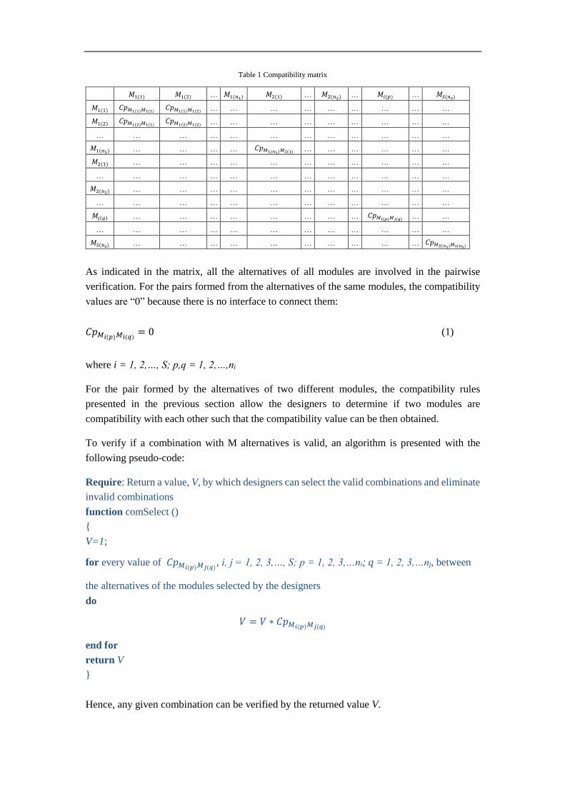
Table 1 Compatibility matrix
𝑀1(1) 𝑀1(2) … 𝑀1(𝑛1) 𝑀2(1) … 𝑀2(𝑛2) … 𝑀𝑖(𝑝) … 𝑀𝑆(𝑛𝑠)
𝑀1(1) 𝐶𝑝𝑀1(1)𝑀1(1) 𝐶𝑝𝑀1(1)𝑀1(2)
… … … … … … … … …
𝑀1(2) 𝐶𝑝𝑀1(2)𝑀1(1) 𝐶𝑝𝑀1(2)𝑀1(2)
… … … … … … … … …
… … … … … … … … … … … …
𝑀1(𝑛1) … … … … 𝐶𝑝𝑀1(𝑛1)𝑀2(1) … … … … … …
𝑀2(1) … … … … … … … … … … …
… … … … … … … … … … … …
𝑀2(𝑛2) … … … … … … … … … … …
… … … … … … … … … … … …
𝑀𝑗(𝑞) … … … … … … … … 𝐶𝑝𝑀𝑖(𝑝)𝑀𝑗(𝑞) … …
… … … … … … … … … … … …
𝑀𝑆(𝑛𝑠) … … … … … … … … … … 𝐶𝑝𝑀𝑆(𝑛𝑠)𝑀𝑠(𝑛𝑠)
As indicated in the matrix, all the alternatives of all modules are involved in the pairwise
verification. For the pairs formed from the alternatives of the same modules, the compatibility
values are “0” because there is no interface to connect them:
𝐶𝑝𝑀𝑖(𝑝)𝑀𝑖(𝑞)= 0 (1)
where i = 1, 2,…, S; p,q = 1, 2,…,ni
For the pair formed by the alternatives of two different modules, the compatibility rules
presented in the previous section allow the designers to determine if two modules are
compatibility with each other such that the compatibility value can be then obtained.
To verify if a combination with M alternatives is valid, an algorithm is presented with the
following pseudo-code:
Require: Return a value, V, by which designers can select the valid combinations and eliminate
invalid combinations
function comSelect ()
{
V=1;
for every value of 𝐶𝑝𝑀𝑖(𝑝)𝑀𝑗(𝑞), i, j = 1, 2, 3,…, S; p = 1, 2, 3,…ni; q = 1, 2, 3,…nj, between
the alternatives of the modules selected by the designers
do
𝑉 = 𝑉 ∗ 𝐶𝑝𝑀𝑖(𝑝)𝑀𝑗(𝑞)
end for
return V
}
Hence, any given combination can be verified by the returned value V.
𝑉 = {1 … 𝑡ℎ𝑒 𝑐𝑜𝑚𝑏𝑖𝑛𝑎𝑡𝑖𝑜𝑛 𝑖𝑠 𝑣𝑎𝑙𝑖𝑑
0 … 𝑡ℎ𝑒 𝑐𝑜𝑚𝑏𝑖𝑛𝑎𝑡𝑖𝑜𝑛 𝑖𝑠 𝑖𝑛𝑣𝑎𝑙𝑖𝑑 (2)
For a system with small or medium size alternative combinations, all valid alternatives can be
verified. With a large number of alternative combinations, this verification method can be
embedded into an optimisation process to exclude the invalid or “sub-optimal” alternatives, e.g.
embedded into the “generate-and-select” optimisation process [61].
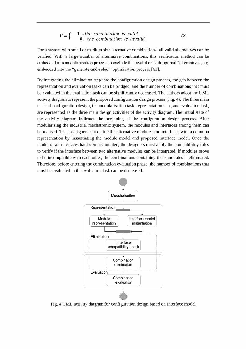
By integrating the elimination step into the configuration design process, the gap between the
representation and evaluation tasks can be bridged, and the number of combinations that must
be evaluated in the evaluation task can be significantly decreased. The authors adopt the UML
activity diagram to represent the proposed configuration design process (Fig. 4). The three main
tasks of configuration design, i.e. modularisation task, representation task, and evaluation task,
are represented as the three main design activities of the activity diagram. The initial state of
the activity diagram indicates the beginning of the configuration design process. After
modularising the industrial mechatronic system, the modules and interfaces among them can
be realised. Then, designers can define the alternative modules and interfaces with a common
representation by instantiating the module model and proposed interface model. Once the
model of all interfaces has been instantiated, the designers must apply the compatibility rules
to verify if the interface between two alternative modules can be integrated. If modules prove
to be incompatible with each other, the combinations containing these modules is eliminated.
Therefore, before entering the combination evaluation phase, the number of combinations that
must be evaluated in the evaluation task can be decreased.
Fig. 4 UML activity diagram for configuration design based on Interface model

In this section, the authors presented the details regarding the proposed configuration design
method that allows designers from different disciplines to define the interfaces of mechatronic
systems with a common representation, verify the compatibility of interfaces, and eliminate
impossible alternative combinations, such that the gap between the representation and
evaluation tasks can be bridged. The applicability of the proposed configuration design method
is demonstrated by a robotic welding system in the following section.
4. Case study
The case study chosen to demonstrate the interface model-based configuration design method
in this section is a robotic welding system. A robotic welding system is a typical mechatronic
system involving highly complex and sophisticated technology for industrial manufacturing.
Today, a considerable amount of work is performed by robotising welding tasks. However, the
problems encountered during the manufacturing process, such as small batch sizes, complex
product shapes, large groove variations, and product tolerances, continue to create major
challenges for robotic welding systems.
The authors provide several solutions for robotising welding tasks by considering the above
challenges. First, robot programs can be generated automatically according to the different
welding seams of different complex products. Secondly, the robotic welding system can
provide more than six degrees of freedom to fulfil different welding tasks required by the
different geometries of complex workpieces. Thirdly, the workpiece tolerance must be
considered and the welding seam tracking function realised by the robotic welding system to
ensure that the generated robot trajectories can be compensated. Finally, automatic collision
avoidance techniques must be integrated into the robotic welding system, and a collision
between two robots, robots with workpieces, or robots with the environment can be detected.
Fig. 5 displays the main modules (blue boxes) and interfaces (purple boxes) among them for
the robotic welding system. The working principle of the robotic welding system is presented
as follows: an offline program subsystem (M1) generates a collision-free trajectory by analysing
the welding seams of the workpiece’s CAD model. Executing the offline program, the robot
control module (M6) and displacement control module (M8) enable two robots (M3 and M4) and
the robot displacement module (M5) to move the welding torch (M11) to the starting point of the
welding seam detected by the position detection module (M2). Using the welding seam tracking
module (M12), the robot trajectories generated by the offline program subsystem can be
compensated such that the welding torch can move along the welding seams precisely.

Fig. 5 Modularisation for robotic welding system
After the modularisation task for the configuration design, the robotic welding system is
decomposed into the modules. However, different choices of standard components or design
solutions, which are considered as different module candidates, can be suggested by discipline-
specific design teams. Table 2 displays the candidates of the standard components or design
solutions for each module of the robotic welding system.
Table 2 Modules and their candidates
Module Candidate
M1 M1(1):Online program
M1(2):Offline program
M2 M2(1): Light source & Camera
M2(2):Fringe pattern & Camera
M3 M3(1):Six-axis robot
M3(2): Cartesian coordinate robot
M4 M4(1): Six-axis robot
M4(2): Cartesian coordinate robot
M5 M5(1): Gantry
M5(2):AGV(Automated Guided Vehicle)
M6
M6(1):PLC(Programmable Logic Controller)
M6(2): Six-axis robot control
M6(3): Cartesian coordinate robot control
M7 M7(1):Shape reconstruction of pattern image
M7(2):linear fitting of workpiece’s edge

M8 M8(1):Gantry control
M8(2):AGV control
M9 M9(1):Contact signal processing
M9(2):Image processing
M10
M10(1):Plasma welding torch control
M10(2):Tandem welding torch control
M10(3):Metal inert-gas welding control
M11
M11(1):Plasma welding torch
M11(2):Tandem welding torch
M11(3):Metal inert-gas welding
M12 M12(1):Contact welding seam tracker
M12(2):Laser welding seam tracker
M13 M13(1):Power supply sub-system
If all combinations of candidates for each module are considered, the designers would have
13,824 different types of combinations. The number of alternative combinations from which
designers must select the most suitable combination is, therefore, overly large.
The information related to the interfaces of the robotic welding system can be managed by the
proposed Interface model. By instantiating the Interface model with the design parameters
related to the proposed candidates, designers can easily verify the interface compatibility using
the compatibility rules, which allow them to eliminate the impossible combinations, thus
decreasing the number of combinations.
Fig. 6 displays an example of the instantiation and implementation of the proposed Interface
model. In this example, the six-axis robot (M3(1)) has a mechanism to provide six degrees of
freedom for the robotic welding system. However, the controller, which is specially designed
for the Cartesian coordinate robot (M6(3)), can only be used to control a robot with three axis.
The UML object diagram in Fig. 6(b) displays the instance of the Interface model created using
the above example. Fig. 6(c) depicts the implementation of the example in the demonstrator.
The compatibility verification result indicates that the interface (I2) between the six-axis robot
(M3(1)) and Cartesian coordinate robot controller (M6(3)) is incompatible. Therefore, the
compatibility value of the interface between M3(1) and M6(3) is “0”, which means that the
combinations including M3(1) and M6(3) are invalid.
As presented in Section 3.2, it is possible that designers cannot accurately determine the port
parameters of components when selecting the most suitable modules among different
alternatives during the preliminary design phase. In this case, a brief description in the class
Document can be used to define a port. The documents of the two ports linked by the interface
are then analysed by designers to determine if the interface is compatible. For example, when
designers attempt to determine which method should be selected to detect the starting point of
the welding seam, the design parameters related to each method can hardly be predicted.
Therefore, the working principle of each method can be described and stored in the class
Document. After analysing the working principle of each method stored in the class Document,
the designers could find that when choosing the method based on the camera and fringe pattern
(M2(2)) to detect the starting point of the welding seam, the shape reconstruction method based
on the comparison between the projected fringe pattern and reflected deformed pattern (M7(1))

should be adopted, whereas it is unlikely to achieve any benefits from the method based on the
linear fitting of the workpiece’s edges (M7(2)). Thus the interface between the two candidates
M2(2) and M7(1) is compatible (i.e. 𝐶𝑝𝑀2(2)𝑀7(1)= 1 ), and candidates M2(2) and M7(2)
are
incompatible with each other (i.e. 𝐶𝑝𝑀2(2)𝑀7(2)= 0).
Fig. 6 Instantiation and implementation of Interface model
By analysing the compatibility between the proposed candidates, the values of the compatibility
matrix can be obtained as indicated in Table 5. According to the algorithm for combination
elimination presented in Section 3.3, the combinations with a “0” for the value of V are
identified as invalid solutions because they include incompatible components. After eliminating
such invalid combinations, the number of possible combinations is reduced to 384. Therefore,
the number of combinations that must be evaluated during the evaluation task has been
significantly reduced.
Finally, considering the performance, cost, efficiency, robustness, and other factors as criteria,
the designers evaluate the proposed alternative combination and select the preferred option
from the list of alternatives by solving the attribute decision-making (MADM) problem. Fig. 7
displays the robotic welding system and its final module candidate selections.

Fig. 7 Robotic welding system and final module candidate selections
In this section, a robotic welding system is used as a case study to demonstrate the proposed
interface model-based configuration design method. The candidates of each module are
proposed and designers from different disciplines can define the interfaces between the modules
with a common representation by instantiating the proposed interface model. Then, applying
the compatibility rules and algorithm for combination elimination, the number of combinations
that must be evaluated during the evaluation task is significantly reduced.

Table 5 Compatibility matrix for lunar roving vehicle
M1(1) M1(2) M2(1) M2(2) M3(1) M3(2) M4(1) M4(2) M5(1) M5(2) M6(1) M6(2) M6(3) M7(1) M7(2) M8(1) M8(2) M9(1) M9(2) M10(1) M10(2) M10(3) M11(1) M11(2) M11(3) M12(1) M12(2) M13(1)
M1(1) 0 0 1 1 1 1 1 1 1 1 1 1 1 1 1 1 1 1 1 1 1 1 1 1 1 1 1 1
M1(2) 0 1 1 1 1 1 1 1 1 1 1 1 1 1 1 1 1 1 1 1 1 1 1 1 1 1 1
M2(1) 0 0 1 1 1 1 1 1 1 1 1 0 1 1 1 1 1 1 1 1 1 1 1 1 1 1
M2(2) 0 1 1 1 1 1 1 1 1 1 1 0 1 1 1 1 1 1 1 1 1 1 1 1 1
M3(1) 0 0 1 1 1 1 1 1 0 1 1 1 1 1 1 1 1 1 1 1 1 1 1 1
M3(2) 0 1 1 1 1 1 0 1 1 1 1 1 1 1 1 1 1 1 1 1 1 1 1
M4(1) 0 0 1 1 1 1 0 1 1 1 1 1 1 1 1 1 1 1 1 1 1 1
M4(2) 0 1 1 1 0 1 1 1 1 1 1 1 1 1 1 1 1 1 1 1 1
M5(1) 0 0 1 1 1 1 1 1 0 1 1 1 1 1 1 1 1 1 1 1
M5(2) 0 1 1 1 1 1 0 1 1 1 1 1 1 1 1 1 1 1 1
M6(1) 0 0 0 1 1 1 1 1 1 1 1 1 1 1 1 1 1 1
M6(2) 0 0 1 1 1 1 1 1 1 1 1 1 1 1 1 1 1
M6(3) 0 1 1 1 1 1 1 1 1 1 1 1 1 1 1 1
M7(1) 0 0 1 1 1 1 1 1 1 1 1 1 1 1 1
M7(2) 0 1 1 1 1 1 1 1 1 1 1 1 1 1
M8(1) 0 0 1 1 1 1 1 1 1 1 1 1 1
M8(2) 0 1 1 1 1 1 1 1 1 1 1 1
M9(1) 0 0 1 1 1 1 1 1 1 0 1
M9(2) 0 1 1 1 1 1 1 0 1 1
M10(1) 0 0 0 1 0 0 1 1 1
M10(2) 0 0 0 1 0 1 1 1
M10(3) 0 0 0 1 1 1 1
M11(1) 0 0 0 1 1 1
M11(2) 0 0 1 1 1
M11(3) 0 1 1 1

M12(1) 0 0 1
M12(2) 0 1
M13(1) 0

5. Discussion
The authors introduced a novel design method to solve the two design problems of
configuration design for complex industrial mechatronic systems identified in Section 1, i.e.
how to achieve high-level multidisciplinary integration during the representation task process
and how to decrease the number of alternative combinations among the alternatives during the
evaluation task process. The proposed configuration design method demonstrates the following
advantages:
For the representation task, different representations for the configurable modules are
proposed based on existing studies on configuration design. Because inadequate attention
has been given to the standardisation of the interactions between the modules, this paper
proposes an Interface model to describe the interactions of modules, which provides a
common representation for the interfaces among the different modules. Therefore, the
compatibility of modules designed by different teams can be verified by compatibility
rules to ensure that the modules can be integrated correctly, thus achieving
multidisciplinary integration during the representation task process.
For the evaluation task, even though different evaluation approaches have been proposed
to solve the multi-attribute decision-making problem, the number of alternative
combinations from which designers evaluate and select the most suitable combination is
overly large owing to the intrinsic complexity of industrial mechatronic systems. Adopting
interface compatibility rules and an elimination algorithm, the proposed configuration
design method bridges the gap between the representation task and evaluation task. It
allows designers to decrease the number of possible combinations, thus significantly
reducing the development lead time.
Even though the effectiveness and applicability of the proposed configuration design method
was demonstrated using a robotic welding system, further studies on the configuration design
method are required.
Current research has demonstrated the effectiveness of configuration design in developing
new systems that satisfy different customer requirements. Requirements have a major role
in configuration design because they specify the problems that the designers must solve.
When specifying the design requirements, designers must consider not only what the
customer requires but also the requirements related to the entire lifecycle of the product.
An architecture with configurable functional modules of a system is proposed according
to the requirements related to the functionality (i.e. functional requirements); however, the
criteria by which designers evaluate the alternative combinations of candidates for each
module are proposed based on the requirements related to performance, cost, efficiency,
robustness, and other factors (i.e. non-functional requirements). If these requirements are
well specified before entering the configuration design process, design errors due to
insufficient familiarity of the requirements related to the following processes can be

avoided. Therefore, the specification of requirements for the configuration design must
receive added attention in the future.
Today, dematerialisation has become a novel development trend for industrial
manufacturing systems. Companies are placing more focus on providing customers with
additional value through the use of services rather than products, because it is believed that
services can bring added value with less environmental impact and without compromising
the customer’s requirements. Therefore, the concept of Industrial Product Service Systems
(IPSS) has been suggested. The proposed design method in this paper can be used to
support the configuration design of complex industrial manufacturing systems effectively
from the perspective of physical features. However, a nonphysical module, called the
service module, must also be considered. Further, the common representation of interfaces
between the physical and service modules must be studied in the future.
6. Conclusions
This paper proposed a novel configuration design method for industrial mechatronic systems
with the objective of bridging the gap between the representation and evaluation tasks of
configuration design. On the one hand, the compatibility of modules designed by different
teams can be verified by the compatibility verification method defined in the Interface model,
allowing the realisation of multidisciplinary integration during the representation task process.
On the other hand, based on the elimination algorithm, the number of alternative combinations
from which designers must select the most suitable combination can be significantly reduced.
The effectiveness and applicability of the proposed configuration design method was
demonstrated using a case study corresponding to a robotic welding system.
Acknowledgements
This project is supported by the National Natural Science Foundation of China (Grant No.
51805437).
References
[1] C. Zhou, Z. Lin, C. Liu, Customer-driven product configuration optimization for
assemble-to-order manufacturing enterprises, The International Journal of Advanced
Manufacturing Technology. 38 (2008) 185–194.
[2] T. Darr, M. Klein, D.L. McGuinness, Special issue: configuration design, Artificial
Intelligence for Engineering Design, Analysis and Manufacturing. 12 (1998) 293–294.

[3] A. Matta, T. Tolio, F. Karaesmen, Y. Dallery, An integrated approach for the
configuration of automated manufacturing systems, Robotics and Computer-Integrated
Manufacturing. 17 (2001) 19–26.
[4] L. Birglen, T. Schlicht, A statistical review of industrial robotic grippers, Robotics and
Computer-Integrated Manufacturing. 49 (2018) 88–97.
[5] J.E. Carryer, R.M. Ohline, T.W. Kenny, Introduction to mechatronic design, Prentice
Hall, Boston, USA, 2011.
[6] J. Gausemeier, U. Frank, J. Donoth, S. Kahl, Specification technique for the
description of self-optimizing mechatronic systems, Research in Engineering Design.
20 (2009) 201–223.
[7] D. Sabin, Product configuration frameworks-a survey, IEEE Intelligent Systems and
Their Applications. 13 (1998) 42–49.
[8] Z.M. Bi, W.A. Gruver, S.Y.T. Lang, Analysis and synthesis of reconfigurable robotic
systems, Concurrent Engineering: Research and Applications. 12 (2004) 145–153.
[9] F. Pahng, N. Senin, D. Wallace, Distribution modeling and evaluation of product
design problems, Computer-Aided Design. 30 (1998) 411–423.
[10] M. Weyrich, P. Klein, M. Laurowski, Y. Wang, Mechatronic engineering of novel
manufacturing processes implemented by modular and sensor-guided machinery, in:
16th IEEE Conference on Emerging Technologies and Factory Automation, Toulouse,
France, 2011.
[11] P.Gu, S.Sosale, Product modularization for life cycle engineering, Robotics and
Computer-Integrated Manufacturing. 15 (1999) 387–401.
[12] C. Daniilidis, D. Hellenbrand, W. Bauer, U. Lindemann, Using structural complexity
management for design process driven modularisation, in: IEEE International
Conference on Industrial Engineering and Engineering Management, Singapore,
Singapore, 2011.
[13] L.-C. Chen, L. Lin, Optimization of product configuration design using functional
requirements and constraints, Research in Engineering Design. 13 (2002) 167–182.
[14] R. Gauthier, S. Pont, Designing systems programs, Prentice Hall, Englewood Cliffs,
USA, 1970.
[15] K. Lameche, N. M.Najid, P. Castagna, K. Kouiss, Modularity in the design of
reconfigurable manufacturing systems, IFAC-PapersOnLine. 50 (2017) 3511–3516.
[16] R. Sanchez, J.T. Mahoney, Modularity, flexibility, and knowledge management in
product and organization design, IEEE Engineering Management Review. 25 (1997)
50–61.
[17] INCOSE, INCOSE systems engineering handbook: a guide for system Life cycle
processes and activities, John Wiley & Sons, 2015.
[18] S.J. Kapurch, NASA Systems engineering handbook, DIANE Publishing, 2010.
[19] H. Komoto, T. Tomiyama, Multi-disciplinary system decomposition of complex
mechatronics systems, CIRP Annals - Manufacturing Technology. 60 (2011) 191–194.
[20] R. Helmer, A. Yassine, C. Meier, Systematic module and interface definition using
component design structure matrix, Journal of Engineering Design. 21 (2010) 647–
675.
[21] P. Hehenberger, F. Poltschak, K. Zeman, W. Amrhein, Hierarchical design models in
the mechatronic product development process of synchronous machines,
Mechatronics. 20 (2010) 864–875.
[22] D. V Steward, Partitioning and tearing systems of equations, Journal of the Society for
Industrial & Applied Mathematics. 2 (1965) 345–365.
[23] T.U. Pimmler, S.D. Eppinger, Integration analysis of product decompositions,
Cambridge, USA, 1994.
[24] C.C. Huang, A. Kusiak, Modularity in design of products and systems, IEEE
Transactions on System, Man and Cybernetics-PART: Systems and Human. 28 (1998)
66–77.
[25] M. V. Martin, K. Ishii, Design for variety: developing standardized and modularized
product platform architectures, Research in Engineering Design. 13 (2002) 213–235.
[26] G. Du, R. J.Jiao, M. Chen, Joint optimization of product family configuration and
scaling design by Stackelberg game, European Journal of Operational Research. 232
(2014) 330–341.
[27] J. Jiao, M.M. Tseng, A methodology of developing product family architecture for
mass customization, Journal of Intelligent Manufacturing. 10 (1999) 3–20.
[28] G. Pahl, W. Beitz, J. Feldhusen, K.-H. Grote, Engineering design: a systematic
approach, Springer-Verlag, London, 2007.
[29] V.-C. Liang, C.J.J. Paredis, A port ontology for conceptual design of systems, Journal
of Computing and Information Science in Engineering. 4 (2004) 206–217.
[30] Y.-T. Tsai, K.-S. Wang, The development of modular-based design in considering
technology complexity, European Journal of Operational Research. 119 (1999) 692–
703.
[31] J. Li, J. Daaboul, S. Tong, M. Bosch-Mauchand, B. Eynard, A design pattern for
industrial robot: User-customized configuration engineering, Robotics and Computer-
Integrated Manufacturing. 31 (2015) 30–39.

[32] M.E. Sosa, S.D. Eppinger, C.M. Rowles, Designing modular and integrative systems,
in: ASME 2000 International Design Engineering Technical Conferences and
Computers and Information in Engineering Conference, Baltimore, USA. 10-13
September, 2000.
[33] B. Bettig, J.K. Gershenson, The representation of module interfaces, International
Journal of Product Development. 10 (2010) 291–317.
[34] U.A. Force, Integrated computer aided manufacturing architecture Part II, Volume
IV—functional modeling manual (IDEF-0), Air Force Materials Laboratory, Wright-
Patterson Air Force Base, USA, 1981.
[35] Y. Wang, W. Lin, S. Wang, J. Huang, Function model of efficient support system
based on improved IDEF0 method, in: 8th International Conference on Reliability,
Maintainability and Safety, Chengdu, China, 2009.
[36] M. Hanafy, H. ElMaraghy, A modular product multi-platform configuration model,
International Journal of Computer Integrated Manufacturing. 28 (2015) 999–1014.
[37] B. Eynard, T. Gallet, P. Nowak, L. Roucoules, UML based specifications of PDM
product structure and workflow, Computers in Industry. 55 (2004) 301–316.
[38] R. Sudarsan, S.J. Fenves, R.D. Sriram, F. Wang, A product information modeling
framework for product lifecycle management, Computer-Aided Design. 37 (2005)
1399–1411. doi:10.1016/j.cad.2005.02.010.
[39] SCRA STEP Application, Step application handbook ISO 10303 Version 3, Hand
Book, 2006.
[40] ISO 10303-203, Industrial automation systems and integration- Product data
representation and exchange-Part 203: Application protocol: Configuration controlled
3D design of mechanical parts and assemblies, International Organization for
Standardization, 2005.
[41] U. Sellgren, M. Törngren, D. Malvius, M. Biehl, PLM for Mechatronics integration,
in: International Conference on Product Lifecycle Management, Bath, UK, 2009.
[42] A. Pandikow, E. Herzog, A. Törne, Integrating systems and software engineering
concepts in AP-233, in: Proceedings of the 2000 INCOSE Symposium, INCOSE,
2000: pp. 831–837.
[43] S.J. Fenves, S. Foufou, C. Bock, R.D. Sriram, CPM : A Core Model for Product Data,
Journal of Computing and Information Science in Engineering. (2006) 1–14.
[44] X.F. Zha, S.J. Fenves, R.D. Sriram, A feature-based approach to embedded system
hardware and sofware co-design, in: ASME Design Engineering Technical
Conference, Long Beach, 2005.

[45] F. Noël, L. Roucoules, The PPO design model with respect to digital enterprise
technologies among product life cycle, International Journal of Computer Integrated
Manufacturing. 21 (2008) 139–145.
[46] Y. Zhang, A. Bernard, An integrated decision-making model for multi-attributes
decision-making (MADM) problems in additive manufacturing process planning,
Rapid Prototyping Journal. 20 (2014) 377–389.
[47] H.E. Tseng, C.C. Chang, S.H. Chang, Applying case-based reasoning for product
configuration in mass customization environments, Expert Systems with Applications.
29 (2005) 913–925.
[48] S. Myung, S. Han, Knowledge-based parametric design of mechanical products based
on configuration design method, Expert Systems with Applications. 21 (2001) 99–107.
[49] M. Dong, D. Yang, L. Su, Ontology-based service product configuration system
modeling and development, Expert Systems with Applications. 38 (2011) 11770–
11786.
[50] C. Zheng, M. Bricogne, J. Duigou, P. Hehenberger, B. Eynard, Knowledge-based
engineering for multidisciplinary systems: Integrated design based on interface model,
Concurrent Engineering. 26 (2018) 157–170.
[51] J. Butler, D. Morrice, P. Mullarkey, A multiple attribute utility theory approach to
ranking and selection, Management Science. 47 (2001) 800–816.
[52] R. Malak, J. Aughenbaugh, C. Paredis, Multi-attribute utility analysis in set-based
conceptual design, Computer-Aided Design. 41 (2009) 214–227.
[53] B. Zhu, Z. Wang, H. Yang, R. Mo, Y. Zhao, Applying fuzzy multiple attributes
decision making for product configuration, Journal of Intelligent Manufacturing. 19
(2008) 591–598.
[54] E. Deciu, E. Ostrosi, M. Ferney, M. Gheorghe, Configurable product design using
multiple fuzzy models, Journal of Engineering Design. 16 (2005) 209–233.
[55] R. Galan, J. Racero, I. Eguia, J. Garcia, A systematic approach for product families
formation in Reconfigurable Manufacturing Systems, Robotics and Computer-
Integrated Manufacturing. 23 (2007) 489–502.
[56] M.R. Abdi, A.W. Labib, A design strategy for reconfigurable manufacturing systems
(RMSs) using analytical hierarchical process (AHP): A case study, International
Journal of Production Research. 41 (2003) 2273–2299.
[57] Z. Afrouzy, S. Nasseri, I. Mahdavi, M. Paydar, A fuzzy stochastic multi-objective
optimization model to configure a supply chain considering new product development,
Applied Mathematical Modelling. 40 (2016) 7545–7570.

[58] C. Zheng, J. Le Duigou, M. Bricogne, B. Eynard, Multidisciplinary interface model
for design of mechatronic systems, Computers in Industry. 76 (2016) 24–37.
[59] ISO10303-233, Industrial automation systems and integration - Product data
representation and exchange - Part 233: Application protocol: Systems engineering,
International Organization for Standardization, 2012.
[60] D. Berardi, D. Calvanese, G. De Giacomo, Reasoning on UML class diagrams,
Artificial Intelligence. 168 (2005) 70–118.
[61] Y. Zhang, W. Wang, A. Bernard, Embedding multi-attribute decision making into
evolutionary optimization to solve the many-objective combinatorial optimization
problems, Journal of Grey System. 28 (2016) 124–143.