Embed Size (px)
Citation preview

Analog and Interface Product Solutions
Design ideas in this guide are based on many of the interface devices available from Microchip Technology. A complete device list andcorresponding data sheets for these products can be found at: www.microchip.com
Interface Products Design GuideUsing CAN, LIN, Ethernet, Infrared Connectivity andGeneral Purpose I/O Expanders
Ethernet ControllerENC28J60
General Purpose I/O ExpanderMCP23X08MCP23X17
Stand-alone CAN ControllerMCP2515
CAN TransceiverMCP2551
CAN I/O ExpanderMCP250XX
LIN TransceiverMCP201
IrDA® Encoder/Decoder
MCP2120MCP2122
IrDA® Protocol Handler
MCP2140MCP2150MCP2155

2 Interface Products Design Guide
The CAN bus (Controller Area Network) protocol was designed to be a high-speed, reliable communication protocol for command and control network applications. Microchip offers a complete line of products to meet the needs of high-performance embedded applications using the CAN protocol, including 8- and 16-bit microcontrollers (MCUs) with integrated CAN, stand-alone CAN controllers, CAN I/O expanders and CAN transceivers. As CAN continues to grow and proliferate into other markets, the need to add CAN to simple sensor circuits increases. In some applications, a simple CAN sensor node can be cost prohibitive due to the higher cost of using a microcontroller with integrated CAN modules. Often the microcontrollers with integrated CAN have extra peripherals, program memory, RAM, etc. which the simple sensor application does not need.In addition to MCUs with integrated CAN, Microchip offers a low cost stand-alone CAN controller with SPI™ interface (MCP2515) which can be paired up with the desired MCU to create an optimized CAN node. The designer does not have to settle for the peripherals offered by an MCU with integrated CAN, but rather the designer can choose the MCU which best
matches the application.Additionally, the four pins used by the MCU for SPI can be regained by using the general purpose inputs and outputs on the MCP2515.The schematic shown below represents a very simple, low cost CAN solution.
SIMPLE FAN CONTROL SOLUTION
Product specifications can be found on page 13.
Used asGeneral Purpose
Inputs
General PurposeOutput
MCU recoversI/O used for SPI™
(GP1-GP5)
AnalogInput
PIC12F875MCU
MCP2515CAN Controller
MCP2551CAN Transceiver
CANBus
X
Controller Area Network (CAN)
CAN DESIGN EXAMPLE: SIMPLE SENSOR NODE
MCP2515 Stand-alone CAN Controller Features:
� Implements CAN V2.0B at 1Mb/s� Masks and filters to filter out unwanted messages� Two receive buffers� Three transmit buffers� High speed SPI interface (10 MHz)� Low voltage operation (2.7-5.5 V)� One shot mode to ensure a message transmission is only attempted once� Start-Of-Frame (SOF) signal pin to detect CAN start-of-frame� Data byte filtering of the first two data bytes� Clock out pin with prescaler can be used as a clock source� Interrupt output pin with selectable interrupt enables� Two buffer full pins (can be used as general purpose outputs)� Three request-to-send pins (can be used as general purpose inputs)
� 18-pin PDIP and SOIC, 20-pin TSSOP
Development Tool Support:
� MCP2510/2515 CAN Developer’s Kit (DV251001)� MCP2515 CAN Controller PICtail™ Demonstration Board (MCP2515DM-PCTL)
Simple Sensor Node Using MCP2515 Stand-alone CAN Controller

Interface Products Design Guide 3
Existing applications that require the addition of CAN will find that the MCP2515 can be used to add CAN connectivity to any application ranging from low-end simple sensor applications, to high-end DSP, 32-bit MCU, ASIC, etc.
Controller Area Network (CAN)
CAN DESIGN EXAMPLE: ADDING CAN TO EXISTING APPLICATIONS
Product specifications can be found on page 13.
Dual CAN Node – The MCP2515 can be used to easily add dual CAN capabilities for a given node.
The diagram below shows CAN added to a high-end application, as many high-end processors do not have embedded CAN peripherals.

4 Interface Products Design Guide
MCP250XXMCP250XX
MCP250XX CAN I/O Expander
The MCP250XX devices operate as I/O expanders for a CAN system. These devices feature several peripherals including eight digital I/O, four 10-bit A/D converters and two 10-bit PWM channels. In addition, the MCP250XX can automatically send messages when an input changes state, including when an analog channel exceeds a preset threshold. The device can also be configured to send A/D and digital I/O messages at regular intervals.Three bits (plus the RTR bit or one more ID bit for direction) are reserved in the identifier/arbitration field of the CAN message to communicate with the MCP250XX. This allows a master CAN node to communicate/control the CAN I/O Expanders via the CAN bus.
Simple Sensor Network
The MCP250XX is ideal for simple, low cost sensor networks. Particularly where the higher layers are proprietary so the system designer can maximize the MCP250XX features. The diagram below shows a four-node sensor network using only one MCU.
Product specifications can be found on page 13.
MCP250XX CAN I/O Expander Features:
� Implements CAN 2.0 B� Masks and filters to filter out unwanted messages� Two receive buffers� Three auto transmit buffers for sending messages automatically� Non-volatile memory for user configuration� Configuration can be modified via the CAN bus� Message scheduling capability – Sends GPIO and analog data� Eight general purpose I/O pins individually selectable as inputs or outputs – Individually selectable transmit-on-change for each input� Four 10-bit analog channels with programmable conversion clock and VREF sources� Individually selectable threshold detection� Two 10-bit PWM outputs� Low voltage operation (2.7-5.5V)
� 14-pin PDIP and SOIC
Development Tools Support:
� MCP250XX CAN I/O Expander’s Developer’s Kit (DV250501)� MCP2515 CAN Controller PICtail™ Demonstration Board (MCP2515DM-PCTL)
CAN DESIGN EXAMPLE: SIMPLE SENSOR NETWORK USING CAN I/O EXPANDER
Controller Area Network (CAN)

Interface Products Design Guide 5
MCP2551 CAN Transceiver Features (Cont.):
� ±250V transient protection on the bus pins� Ground fault (permanent dominant) detection on the transmit input pin – Keeps faulty transmitters from bringing down the bus due to a permanent dominant condition� Externally controlled slope on the bus pins to reduce RFI emissions� Power on reset and brown out detection� Unpowered nodes will not disturb the bus
� Up to 112 nodes can be connected
Development Tools Support:
� MCP2510/2515 CAN Developer’s Kit (DV251001)� MCP2515 CAN Controller PICtail™ Demonstration Board (MCP2515DM-PCTL)� MCP250XX CAN I/O Expander Developer’s Kit (DV250501)� SOIC 8-Lead Evaluation Board (SOIC8EV)
MCP2551 CAN Transceiver
The MCP2551 is a high speed CAN transceiver which serves as an interface between the CAN bus and the CAN controller. The MCP2551 implements the ISO 11898-2 physical layer requirements which is by far the most common physical layer for CAN.The MCP2551 converts between logic levels generated by the CAN controller and differential signal levels on the bus. The differential signal is less prone to electrical disturbances. The MCP2551 protects the CAN controller from electrical anomalies such as voltage spikes, short circuits and other electrical transients on the bus.The diagram below shows the basic connections for connecting the MCP2551.
MCP2551 CAN Transceiver Features:
� Implements ISO 11898-2 physical layer requirements� Suitable for 12V and 24V systems� ±40V short circuit protection on the bus pins – Automatic thermal shutdown protection
Controller Area Network (CAN)
DESIGN EXAMPLE: BASIC CONNECTIONS USING CAN TRANSCEIVER
Product specifications can be found on page 13.
Basic Connections for Connecting the MCP2551

6 Interface Products Design Guide
MCP201 LIN Transceiver
LIN is a low speed network (20 kbaud) intended for automotive and industrial applications where the speed and robustness of CAN is not needed and where low cost is essential. The MCP201 is a LIN transceiver which provides the interface between the LIN bus and the LIN controller. The MCP201 converts between CMOS/TTL levels and LIN levels.The diagram shows a typical implementation of a LIN node using the MCP201.
MCP201 LIN Transceiver Features:
� Supports LIN rates up to 20 kbaud� 40V load dump protected� Operates from 6V to 18V
MCP201 LIN Transceiver Features (Cont.):
� Robust LIN bus pin – Protected against ground shorts – Protected against loss of ground – Automatic thermal shutdown – High current drive (40 mA to 200 mA)� Built in voltage regulator (LDO) – 5V output (±5 % tolerance) – 50 mA maximum output current� Internal thermal overload protection
� Internal short circuit protection
Development Tools Support:
� PICDEM™ CAN-LIN 1, 2 and 3 Demonstration Boards (DM163007, DM163011, DM163015)� PICDEM LIN Demonstration Board (DM163005)� SOIC 8-Lead Evaluation Board (SOIC8EV)
Optional Components
Optional Components
Wake-up
DESIGN EXAMPLE: TYPICAL APPLICATIONS USING LIN TRANSCEIVER
Local Interconnect Network (LIN)
Product specifications can be found on page 13.
Typical MCP201 Application
Typical LIN Network Configuration

Interface Products Design Guide 7
ETHERNET DESIGN EXAMPLE: ENC28J60 ETHERNET CONTROLLER
Ethernet
ENC28J60 Ethernet Controller
The ENC28J60 is a 28-pin, IEEE 802.3 compliant stand-alone Ethernet controller with on board MAC and PHY, 8 Kbytes of Buffer RAM and SPI™ interface. These features, combined with Microchip’s free TCP/IP software stack for PIC18 microcontrollers, provide the smallest whole-product Ethernet solution for embedded applications. With a small package size including a 6x6 mm QFN, the ENC28J60 provides a low-pin count, cost-effective and easy-to-use solution for remote communication with embedded applications.
ENC28J60 Ethernet Controller Features:
General
� IEEE 802.3 compatible Ethernet Controller� Integrated MAC and 10BASE-T PHY� 8 Kbyte Transmit/Receive Packet Dual Port Buffer SRAM� Receiver and Collision Squelch Circuit� Automatic Polarity Detection and Correction� Programmable Automatic Retransmit on Collision� Programmable Padding and CRC Generation� Programmable Automatic Rejection of Erroneous Packets
EthernetTransformer
INTx
AN833AN870
SPI
I/O
SDO
SDI
SCK
TCP/IPStack
ENC28J60
CS
SI
SO
SCK
INT,WOL
TX/RXBuffer
MAC PHY
RJ45MCU
Typical Ethernet Application
ENC28J60 Ethernet Controller Features (Cont.):
Buffer
� Configurable transmit/receive buffer size� Hardware managed circular receive FIFO� Byte-wide random and sequential access� Internal DMA for fast memory copying� Hardware assisted IP checksum calculation� Operates from 6V to 18V
PHY
� Wave shaping output filter� Loopback mode
MAC
� Support for Unicast, Multicast and Broadcast packets� Programmable pattern matching of up to 64 bytes within packet at user defined offset� Programmable wake-up on multiple packet formats, including Magic Packet®, Unicast, Multicast, Broadcast, specific packet match or any packet� Loopback mode
Development Tools Support:
� Ethernet PICtail Daughter Board (AC164121)� Microchip TCP/IP software stack (AN833, AN870)

8 Interface Products Design Guide
MCP2150 and MCP2155 IrDA® ProtocolStack Controller
The MCP215X devices allow an embedded systems designer to interface to popular IrDA® standard devices (such as PDAs and PCs) using the embedded systems host controller UART and some I/O pins.The MCP215X implements the IrDA standard stack. At the application layer, the IrCOMM protocol (9-wire “cooked” service class) is the IrDA standard replacement for the serial cable. Thus the embedded systems designer will interface to the MCP215X as if it was a serial cable. The MCP215X does not implement the IR transceiver of the physical layer.
MCP215X Features:
� Implements the IrDA standard including: – IrLAP – IrLMP – IAS – TinyTP – rCOMM (9-wire “cooked” service class)� UART to IrDA standard encoder/decoder – Interfaces with UARTs and infrared transceivers� UART support to Data Terminal Equipment (DTE) interfaces (MCP2150) or Data Communication Equipment (DCE) interfaces (MCP2155)
MCP215X Features (Cont.):
� Supports 1.63 μs bit width for transmit/receive� Independent UART and IR baud rates � UART baud rates: – 906 kbaud – 19.2 kbaud – 57.6 kbaud – 115.2 kbaud� IrDA baud rates: – 906 kbaud – 19.2 kbaud – 38.4 kbaud – 57.6 kbaud – 115.2 kbaud� 64 byte data packet� Programmable device ID� Operates as a Slave Device
� Hardware pin for low power mode
Development Tools Support:
� MCP2120/MCP2150 Developer’s Kit (DM163008)� MCP215X Data Logger Demonstration Board (MCP215XDM)� MCP215X/40 Developer’s Daughter Board (MCP215XEV-DB)
MCP215X
Note 1: The CD and RI signals have different directions (and functions) between the MCP2150 and the MCP2155.
Note 2: Please refer to MCP2150 Data Sheet (DS21655) or MCP2155 Data Sheet (DS21690) for the function of the Host
UART signals (TX, RX, RTS, CTS, DSR, CD and RI). Not all signals may be required in your application (see AN858).
Infrared Communications
DESIGN EXAMPLE: INFRARED DATA APPLICATIONS
Product specifications can be found on page 13.
MCP215X Typical System Block Diagram

Interface Products Design Guide 9
Note 1: Not all microcontroller I/O pins are required to be connected to the MCP2140.
MCP2140 IrDA® Protocol Stack Controller
MCP2140 has all of the same features as the MCP2150 except:� Supports discrete IR circuitry instead of integrated infrared transceivers� Host UART and IR interface fixed at 9600 baud� Fixed device ID� Wake-up on IR detectThe diagram below shows a typical system block diagram and typical discreet IR transceiver.
DESIGN EXAMPLE: USING 9600 BAUD IrDA® PROTOCOL STACK CONTROLLER
IrDA® Protocol Stack Controller
Development Tools Support:
� MCP2140 Wireless Temperature Sensor Demonstration Board (MCP2140DM-TMPSNS)
� MCP215X/40 Developer’s Daughter Board (MCP215XEV-DB)
MCP2140 Typical System Block Diagram
Product specifications can be found on page 13.

10 Interface Products Design Guide
Product specifications can be found on page 13.
MCP2120 Infrared Encoder/Decoder
Unlike the MCP2150 and MCP2140 which implement the IrDA® stack, the MCP2120 is simply an encoder/decoder. This allows the application processor to implement all or part of the IrDA stack, or implement a custom protocol using IR.
MCP2120 Features:
� UART to IrDA encoder/decoder� Supports IrDA physical layer specification (v.1.3)� Interfaces with IrDA compliant transceivers� Interfaces to standard UARTs
MCP2120 Features (Cont.):
� Operates up to the full standard IrDA data rate (115.2 kbaud) – 312.5 kbaud maximum� Low power mode
� Hardware and software baud control
Development Tools Support:
� MCP2120/MCP2150 Developer’s Kit (DM163008)� MCP212X Developer’s Daughter Board (MCP212XEV-DB)
DESIGN EXAMPLE: USING AN IrDA® ENCODER/DECODER
IrDA® Protocol Stack Controller
MCP2120 Typical System Block Diagram
MCP2122 Infrared Encoder/Decoder
The MCP2122 is a stand-alone IrDA standard encoder/decoder device. The MCP2122 has two interfaces: the host UART interface and the IR interface. The host UART interfaces to the UART of the host controller. The IR interface connects to an infrared (IR) optical transceiver circuit, which converts electrical pulses into IR light (encode) and converts IR light into electrical pulses (decode).
MCP2122 Features:
� UART to IrDA encoder/decoder� Supports IrDA physical layer specification (v.1.3)� Interfaces with IrDA compliant transceivers� Interfaces to standard UARTs� Operates up to the full standard IrDA data rate (115.2 kbaud)� Low power mode
� 16X clock input
Development Tools Support:
� MCP212X Developer’s Daughter Board (MCP212XEV-DB)� SOIC 8-Lead Evaluation Board (SOIC8EV)
16X CLK
RESET
MCP2122 Typical System Block Diagram

Interface Products Design Guide 11
Product specifications can be found on page 14.
Configuration/Control
Registers
RESET
INT
A2:A0
VDD
VSS
Serializer/Deserializer
Control
GPIO
GP0
GP1
GP2
GP3
GP4
GP5
GP6
GP7
8
8
SerialInterface
I2C
™S
PI™
InterruptLogic
POR
MCP23S08
MCP23008
SCK
SI
SO
DecodeA1:A0
SCL
SDA
Decode
MCP23008/MCP23S08 8-bit I/O Expander
The MCP23X08 device provides 8-bit, general purpose, parallel I/O expansion for I2C™ bus or SPI™ applications. The two devices differ in the number of hardware address pins and the serial interface:MCP23008 – I2C interface; three address pinsMCP23S08 – SPI interface; two address pinsThe MCP23X08 consists of multiple 8-bit confi guration registers for input, output and polarity selection.
MCP23008 Features:
� High speed I2C interface: – 100 kHz – 400 kHz – 1.7 MHz� Three hardware address pins for up to eight devices on the bus� Configurable interrupt output pin� Configurable interrupt source� High current drive for each output (25 mA)� Eight individually selectable I/O pins� Low standby current (1 μA max)
DESIGN EXAMPLE: USING A GENERAL PURPOSE PARALLEL 8-BIT I/O PORT EXPANDER
General Purpose I/O Expanders
MCP23008/MCP23S08 Typical System Block Diagram
MCP23S08 Features:
� High speed SPI interface: – 10 MHz� Two hardware address pins for up to four devices on the bus� Configurable interrupt output pin� Configurable interrupt source� High current output drive for each pin (25 mA)� Eight individually selectable I/O pins
� Low standby current (1 μA max)
Development Tools Support:
� MCP23X08 Evaluation Board (MCP23X08EV)

12 Interface Products Design Guide
Configuration/Control
Registers
RESET
INTA
A2:A0
Serializer/Deserializer
Control
GPIO
GPA7
GPA6
GPA5
GPA4
GPA3
GPA2
GPA1
GPA0
16
8
SerialInterface
I2C
™
InterruptLogic
MCP23017
SCL
SDA
Decode GPIO
GPB7
GPB6
GPB5
GPB4
GPB3
GPB2
GPB1
GPB0
INTB
SP
I™
MCP23S17
CS
SCK
SI
SO
DecodeA2:A0
MCP23017/MCP23S17 16-bit I/O Expander
The MCP23017/MCP23S17 (MCP23X17) device family provides 16-bit, general purpose parallel I/O expansion for I2C™ bus or SPI™ applications. The two devices differ only in the serial interface.MCP23017 – I2C interfaceMCP23S17 – SPI interfaceThe MCP23X17 consists of multiple 8-bit confi guration registers for input, output and polarity selection.
MCP23017 Features:
� High speed I2C interface: – 100 kHz – 400 kHz – 1.7 MHz� Three hardware address pins for up to eight devices on the bus� Configurable interrupt output pin� Configurable interrupt source� High current drive for each output (25 mA)� Sixteen individually selectable I/O pins� Low standby current (1 μA max)
MCP23017/MCP23S17 Typical System Block Diagram
MCP23S17 Features:
� High speed SPI interface� Three hardware address pins for up to eight devices on the bus� Configurable interrupt output pin� Configurable interrupt source� High current drive for each output (25 mA)� Sixteen individually selectable I/O pins� Low standby current (1 μA max)
Development Tools Support:
None available at this time.
General Purpose I/O Expanders
DESIGN EXAMPLE: USING A GENERAL PURPOSE PARALLEL 16-BIT I/O PORT EXPANDER
Product specifications can be found on page 14.
Interface Products Design Guide 13
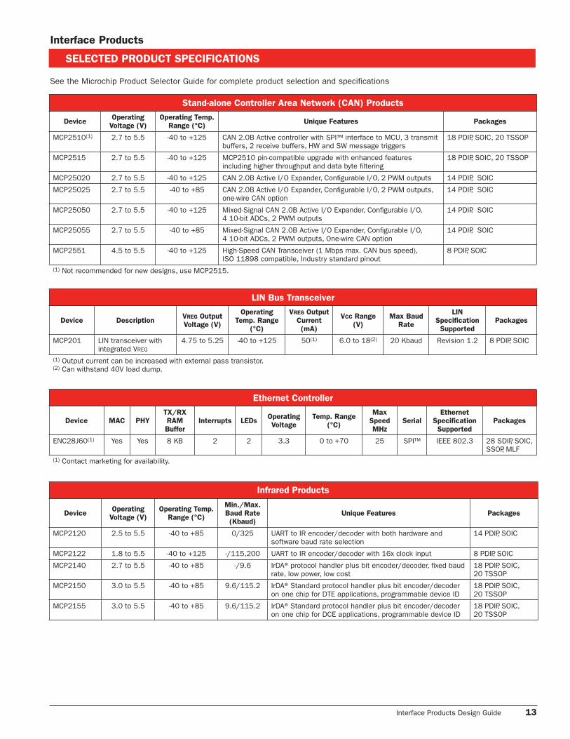
SELECTED PRODUCT SPECIFICATIONS
See the Microchip Product Selector Guide for complete product selection and specifications
Infrared Products
DeviceOperating
Voltage (V)
Operating Temp.
Range (°C)
Min./Max.
Baud Rate
(Kbaud)
Unique Features Packages
MCP2120 2.5 to 5.5 -40 to +85 0/325 UART to IR encoder/decoder with both hardware and software baud rate selection
14 PDIP, SOIC
MCP2122 1.8 to 5.5 -40 to +125 -/115,200 UART to IR encoder/decoder with 16x clock input 8 PDIP, SOIC
MCP2140 2.7 to 5.5 -40 to +85 -/9.6 IrDA® protocol handler plus bit encoder/decoder, fi xed baud rate, low power, low cost
18 PDIP, SOIC, 20 TSSOP
MCP2150 3.0 to 5.5 -40 to +85 9.6/115.2 IrDA® Standard protocol handler plus bit encoder/decoder on one chip for DTE applications, programmable device ID
18 PDIP, SOIC,20 TSSOP
MCP2155 3.0 to 5.5 -40 to +85 9.6/115.2 IrDA® Standard protocol handler plus bit encoder/decoder on one chip for DCE applications, programmable device ID
18 PDIP, SOIC,20 TSSOP
LIN Bus Transceiver
Device DescriptionVREG Output
Voltage (V)
Operating
Temp. Range
(°C)
VREG Output
Current
(mA)
VCC Range
(V)
Max Baud
Rate
LIN
Specifi cation
Supported
Packages
MCP201 LIN transceiver with integrated VREG
4.75 to 5.25 -40 to +125 50(1) 6.0 to 18(2) 20 Kbaud Revision 1.2 8 PDIP, SOIC
(1) Output current can be increased with external pass transistor.(2) Can withstand 40V load dump.
Interface Products
Stand-alone Controller Area Network (CAN) Products
DeviceOperating
Voltage (V)
Operating Temp.
Range (°C)Unique Features Packages
MCP2510(1) 2.7 to 5.5 -40 to +125 CAN 2.0B Active controller with SPI™ interface to MCU, 3 transmit buffers, 2 receive buffers, HW and SW message triggers
18 PDIP, SOIC, 20 TSSOP
MCP2515 2.7 to 5.5 -40 to +125 MCP2510 pin-compatible upgrade with enhanced features including higher throughput and data byte fi ltering
18 PDIP, SOIC, 20 TSSOP
MCP25020 2.7 to 5.5 -40 to +125 CAN 2.0B Active I/O Expander, Confi gurable I/O, 2 PWM outputs 14 PDIP, SOIC
MCP25025 2.7 to 5.5 -40 to +85 CAN 2.0B Active I/O Expander, Confi gurable I/O, 2 PWM outputs, one-wire CAN option
14 PDIP, SOIC
MCP25050 2.7 to 5.5 -40 to +125 Mixed-Signal CAN 2.0B Active I/O Expander, Confi gurable I/O,4 10-bit ADCs, 2 PWM outputs
14 PDIP, SOIC
MCP25055 2.7 to 5.5 -40 to +85 Mixed-Signal CAN 2.0B Active I/O Expander, Confi gurable I/O,4 10-bit ADCs, 2 PWM outputs, One-wire CAN option
14 PDIP, SOIC
MCP2551 4.5 to 5.5 -40 to +125 High-Speed CAN Transceiver (1 Mbps max. CAN bus speed),ISO 11898 compatible, Industry standard pinout
8 PDIP, SOIC
(1) Not recommended for new designs, use MCP2515.
Ethernet Controller
Device MAC PHY
TX/RX
RAM
Buffer
Interrupts LEDSOperating
Voltage
Temp. Range
(°C)
Max
Speed
MHz
Serial
Ethernet
Specifi cation
Supported
Packages
ENC28J60(1) Yes Yes 8 KB 2 2 3.3 0 to +70 25 SPI™ IEEE 802.3 28 SDIP, SOIC, SSOP, MLF
(1) Contact marketing for availability.

14 Interface Products Design Guide
Related Support Material
The following Application Notes and Tech Briefs are available on the Microchip web site: www.microchip.com.
Application Notes
CAN Communications
AN212: Smart Sensor CAN Node Using the MCP2510 and PIC16F876Demonstrates a way to implement a simple input pressure switch connected to a node board, along with a visual light source to display the value in terms of brightness. Several uses for differ ent types of inputs and outputs can be implemented by using the basic techniques from this design.
AN215: A Simple CAN Node Using the MCP2510 and PIC12C67XDescribes the design, develop ment and implementation of asmart, low cost, stand-alone Controller Area Network (CAN)node. Com bines the 8-pin PIC12C672 with the 18-pin MCP2510 stand-alone CAN controller to create a fully autonomous CAN node, which supports both “time-based” and “event driven” message transmission.
AN228: A CAN Physical Layer DiscussionA discussion of the many network protocols which are described using the seven layer Open System Interconnection (OSI) mode.
AN739: An In-Depth Look at the MCP2510Focuses on “using” the MCP2510 including the minimal confi guration necessary to enable the CAN node, features and implementation, a detailed discussion of many of the registers and potential pitfalls during implementation.
AN754: Understanding Microchip’s CAN Module Bit TimingInvestigates the relationships between bit timing parameters, the physical bus propagation delays and oscillator tolerances throughout the system as they pertain to Microchip’s CAN module and assists in optimizing the bit timing for given physical system attributes.
AN816: A CAN System Using Multiple MCP25025 I/O ExpandersDescribes a control system for a scissor-lift, which is essentially a mobile work platform enabling the user to reach relatively high places. All of the operations and movements use one Master Node and three I/O Expander Nodes.
AN872: Upgrading from the MCP2510 to the MCP2515This application note discusses the differences between theMCP2510 and MCP2515 (and possible impact of these differences) in an effort to assist with the upgrade process.
AN873: Using the MCP2515 CAN Developer’s KitServes as a three-part tutorial for the MCP2515/2510 developer’s kit and discusses the three software tem plates in detail as well as the important menu items.
Infrared Communications
AN858: Interfacing The MCP215X to a Host ControllerDiscusses the operation of the MCP215X Host UART interface, implements an embedded system (as an IrDA® Standard Secondary device), and describes the setup of PDA devices to operate as the IrDA Standard Primary device.
AN888: Programming the Palm OS™ for Embedded IR ApplicationsStrives to impart core, fundamental programming concepts and design considerations for the development of Palm OS application programs. Attention is given to each of the fundamental areas of Palm OS application development in the “C” programming language.
AN926: Programming the Pocket PC™ OS for Embedded IR ApplicationsThis application note details the tools, supporting technologies and procedures for the development of infrared applications on Windows Mobile™ based devices.
AN941: Programming Windows XP® for Embedded IR ApplicationsThis application note details the tools, supporting technologies and procedures for the development of infrared applications on a Windows XP® based PC.
SELECTED PRODUCT SPECIFICATIONS
Interface Products
Serial Peripherals
Device DescriptionOperating
Voltage (V)
Operating Temp.
Range (°C)
Bus
Type
Max. Bus
Frequency
(kBits/s)
Features Packages
MCP23008MCP23S08
8-bit I/O Port Expander
1.8 to 5.5 -40 to +125 I2C™ 1.7 MHz 3 HW address inputs, HW interrupt, 25 mA source/sink capability per I/O
18 PDIP, SOIC, 20 TSSOP
SPI™ 10 MHz 3 HW address inputs, 2 HW interrupt, 25 mA source/sink capability per I/O
MCP23016(1) 16-bit I/O Port Expander
2.0 to 5.5 -40 to +85 I2C™ 400 3 HW address inputs, HW interrupt, 25 mA source/sink capability per I/O
28 PDIP, SOIC, SSOP
MCP23017MCP23S17
16-bit I/O Port Expander
1.8 to 5.5 -40 to +125 I2C™ 1.7 MHz 3 HW address inputs, 2 HW interrupt, 25 mA source/sink capability per I/O
28 PDIP, SOIC, SSOP, QFNSPI™ 10 MHz
(1) Not recommended for new designs.

Interface Products Design Guide 15
AN927: Data Throughput and the MCP215XDiscusses techniques that will improve the data transfer throughput between IrDA standard Primary Device and embedded system.
AN946: Interfacing the MCP2122 to the Host ControllerThis application note discusses methods with which to interface the MCP2122 to a Host Controller and how to use the PICmicro MCU’s CCP and Timer 2 modules to generate the 16XCLK signal.
AN243: Fundamentals of the Infrared Physical LayerDescribes the fundamentals of the infrared physical layer, the IrDA standard and selecting the proper discrete emitter and photodiode components for circuit implementation.
TB073: Selecting an MCP21XX Device for IrDA® ApplicationsThis document will help you select which MCP21XX family device is a good fit for your application.
AN923: Using the MCP2120 Developer’s Board for “IR Sniffing”Discusses the implementation of an “IR Sniffer” using the MCP2120 Developer’s board connect to a PC running a program call “Listen32.”
AN756: Using the MCP2120 for Infrared CommunicationsA discussion regarding the encod ing/decoding function in the MCP2120 which is performed as specified in the phys ical layer component of the IrDA® standard known as the “IrPHY.”
TB059: Using The MCP2150 Developer’s Board With the MCP2155This technical brief describes how the MCP2150 Developer’s Board can be used for development of MCP2155 applications, and focuses on the Host UART signals from the U2 socket (MCP2150/MCP2155 ) to the MAX3238 device (U1) and the Header (J1).
AN758: Using the MCP2150 To Add IrDA® Standard Wireless ConnectivityMicrochip’s MCP2150 provides support for the IrDA standard protocol stack plus bit encoding/ decoding. This application note discusses the encoding/decoding functionality of this device.
TB046: Connecting the MCP2150 To The Psion Operating SystemSince the MCP2150 is a protocol handler supporting IrDA® stan dards plus an encoder/decoder, it can be used as a “Virtual Connector,” a wire less link between an embedded application and an IrDA standard host. This host can be a handheld device using the Psion OS. The Psion OS is generally used for small Personal Digital Assistants (PDA) devices.
TB047: Connecting the MCP2150 to the Windows CE® Operating SystemSimilar to TB046 but using a Microsoft® Windows® CE Operating System (OS). Windows CE is an excellent host platform for use with the MCP2150 because of the light weight, low cost, ease of use and portability of these devices. Microsoft Windows includes a terminal client that can easily be used to demonstrate this capability.
Interface Products
RELATED SUPPORT MATERIAL
TB048: Connecting the MCP2150 to the Windows® Operating SystemThis technical brief is similar to TB046, however, in this application the host is a Personal Computer (PC) using Microsoft Windows which includes a terminal client that can easily be used to demonstrate the capabilities of the MCP2150.
TB049: Connecting the MCP2150 to the Palm™ Operating SystemSimilar to TB046 but using the Palm Operating System (OS) Personal Digital Assistants (PDA) devices are an excellent host platform for use with the MCP2150 because of the light weight, low cost, ease of use and portability of these devices.
I/O Expander
AN972: I/O Expansion Using the MCP23X08 and PIC10F202This application note discusses using the MCP23008 and MCP23S08 GPIO Expanders with a 6-pin PIC10F202 microcontroller unit (MCU). The discussion is based on the MCP23X08 Evaluation Board, P/N: MCP23008DM.
LIN Bus Communications
AN729: LIN Protocol Implementation Using PICmicro® MCUsThis application note is intended to provide a broad overview of the LIN bus and provide a high level look at how it works, how to imple ment a Slave node on a PICmicro device and what it’s designed to do.
AN829: LightKeeper Automotive Lighting Control ModuleThis application note describes an automotive exterior lighting control module using a PIC16C433.
Ethernet Communications
AN833: The Microchip TCP/IP StackThis application note details Microchip’s own freely available implementation of the TCP/IP Stack. This TCP/IP Stack is a suite of programs that provide services to standard TCP/IP-based applications (HTTP Server, Mail Client, etc.), or can be used in a custom TCP/IP or UDP/IP-based application.
AN870: An SNMP Agent for the Microchip TCP/IP StackThis application note provides one of the key components of the SNMP Management system: the SNMP Agent that runs on the managed device. The simple agent presented here is designed to run on Microchip’s PICmicro® microcontrollers and is implemented using services provided by the free Microchp TCP/IP stack.

Robustness
� MOSFET Drivers lead the industry in latch-up immunity/stability
Low-Power/Low-Voltage
� Op Amp family with the lowest power for a given gain bandwidth� 600 nA/1.4V/10 kHz bandwidth Op Amps� 1.8V charge pumps and comparators� Lowest power 12-bit ADC in SOT-23 package
Integration
� One of the first-to-market with integrated LDO with Reset and Fan Controller with temperature sensor� PGA integrates MUX, resistive ladder, gain switches, high-performance amplifier, SPI™ interface
Space Savings
� Resets and LDOs in SC70; ADCs in 5-pin SOT-23A� CAN and IrDA®standard protocol stack embedded in an 18-pin package
Accuracy
� Offset trimmed after packaging using non-volatile memory
Innovation
� Low pin-count embedded IrDA® standard stack, FanSense™ technology� Select Mode™ operation
For more information, visit the Microchip web site at www.microchip.com
Microchip Technology Inc. is a leading provider of microcontroller, analog and memory products that provide risk-free product development, lower total system cost and faster time-to-market for thousands of diverse customer applications worldwide. Microchip’s commitment to quality and innovation coupled with world-class development tools, dependable delivery and outstanding technical support sets us apart.
Thermal Management
PowerManagement
TemperatureSensors
Fan SpeedControllers/Fan FaultDetectors
LDO & Switching Regulators
Charge Pump DC/DC Converters
Power MOSFET Drivers
PWM Controllers
System Supervisors
Voltage Dectectors
Voltage References
BatteryManagement
Li-Ion/Li-PolymerBattery Chargers
Smart Battery Managers
Linear
Op Amps
ProgrammableGain Amplifiers
Comparators
Linear Integrated Devices
Mixed-Signal
A/D Converter Families
Digital Potentiometers
System D/A Converters
V/F and F/V Converters
Interface
CAN Peripherals
Infrared Peripherals
LIN Transceiver
Serial Peripherals
Ethernet Controller
www.microchip.com
Microchip Technology Inc. • 2355 W. Chandler Blvd. • Chandler, AZ 85224-6199
Information subject to change. The Microchip name and logo, the Microchip logo, PIC and PICmicro are registered trademarks of Microchip Technology Incorporated in the U.S.A. and other countries. FanSense, Select Mode, MXLAB and MXDEV are trademarks of Microchip Technology Incorporated in the U.S.A. and other countries. All other trademarks mentioned herein are property of their respective companies. © 2005, Microchip Technology Incorporated. All Rights Reserved. Printed in the U.S.A. 9/05 DS21883B
*DS21883B*
MICROCONTROLLERS • DIGITAL SIGNAL CONTROLLERS • ANALOG • SERIAL EEPROMS
Analog and Interface Products
Analog and Interface Attributes