Embed Size (px)
Citation preview

Test Methods: ASTM D6916 & NCMA SRWU-2 Test Facility: Bathurst, Clarabut Geotechnical Testing, Inc.
Block Type: 28" Positive Connection (PC) Block Test Dates:
6.75" KNOB INTERFACE SHEAR DATA(a) 6.75" KNOB INTERFACE SHEAR CAPACITY
Test Normal Service State Peak
No. Load, lb/ft Shear, lb/ft(c) Shear, lb/ft
1 522 838 1,724
2 19,209 11,324 11,324
3 16,303 11,252 11,252
4 13,612 11,036 11,036
5 11,075 10,462 10,462
6 11,074 11,060 11,252
7 8,299 10,408 11,204
8 5,854 8,337 9,935
9 3,077 5,722 6,153
10 10,981 10,821 11,252
Peak Shear: Sp = 1,178 + N tan 54°, Sp(max) = 10,970 lb/ft(e)
10/21/2011 - 6.75" Shear Knob Test
10/14/2011 - 10" Shear Knob Test
Knob Shear
Knob Shear
Knob Shear
Test Stopped
Knob Shear
Test Stopped
Test Stopped
Failure(d)
Test Stopped
Test Stopped
Observed
Test Stopped
0
2,000
4,000
6,000
8,000
10,000
12,000
0 4,000 8,000 12,000 16,000 20,000
She
ar C
apac
ity, l
b/ft
Normal Load lb/ft
Peak Shear (Sp)
Service State Shear (Sss)
p p( a )
Service State Shear: Sss = 616 + N tan 52°, Sss(max) = 10,970 lb/ft(e)
10" KNOB INTERFACE SHEAR DATA(b) 10" KNOB INTERFACE SHEAR CAPACITYTest Normal Service State Peak
No. Load, lb/ft Shear, lb/ft(c) Shear, lb/ft
1 19,619 11,300 11,300
2 16,007 11,300 11,300
3 13,546 11,371 11,371
4 11,042 11,371 11,371
5 8,400 11,204 11,204
6 10,999 11,252 11,252
7 10,922 11,252 11,252
8 5,786 10,414 11,156
9 3,137 7,469 10,174
10 522 3,926 6,033
Peak Shear: Sp = 6,061 + N tan 44°, Sp(max) = 11,276 lb/ft
Service State Shear: Sss = 3,390 + N tan 51°, Sss(max) = 11,276 lb/ft
Test Stopped
Test Stopped
Test Stopped
Test Stopped
Test Stopped
Test Stopped
Test Stopped
Observed
Failure(d)
Test Stopped
Test Stopped
Test Stopped
Normal Load, lb/ft
The information contained in this report has been compiled by Redi-Rock International, LLC as a recommendation of peak interface shear capacity. It is accurate to the best of our knowledge as of the date of its issue. However, final determination of the suitability of any design information and the appropriateness of this data for a given design purpose is the sole responsibility of the user. No warranty of performance is expressed or implied by the publishing of the foregoing laboratory test results. Issue date: February 21, 2012.
(a) The maximum 28-day compressive strength of all concrete blocks tested in the 6.75 inch knob interface shear test series was 4,694 psi.(b) The 28-day compressive strength of all concrete blocks tested in the 10 inch knob interface shear test series was 4,474 psi. (c) Service State Shear is measured at a horizontal displacement equal to 2% of the block height. For Redi-Rock blocks, displacement = 0.36 inches.(d) In most cases, the test was stopped before block rupture or knob shear occured to prevent damage to the test apparatus. (e) Design shear capacity inferred from the test data reported herein should be lowered when test failure results from block rupture or knob shear if the compressive strength of the blocks used in design is less than the blocks used in this test. The data reported represents the actual laboratory test results. The equations for peak and service state shear conditions have been modified to reflect the interface shear performance of concrete with a minimum 28-day compressive strength equal to 4,000 psi. No further adjustments have been made. Appropriate factors of safety for design should be added.
0
2,000
4,000
6,000
8,000
10,000
12,000
0 4,000 8,000 12,000 16,000 20,000
She
ar C
apac
ity, l
b/ft
Normal Load, lb/ft
Peak Shear (Sp)
Service State Shear (Sss)

Redi-Rock PC block (6 inch dome) Interface Shear Project # 211019
Series # BCGT3106
Bathurst, Clarabut Geotechnical Testing, Inc. 21 October 20111 of 8Telephone: (613) 384 6363 Email: [email protected]
REPORTRESULTS OF
REDI-ROCK 28 INCH PC BLOCK UNIT(6 INCH DOME)
INTERFACE SHEAR CAPACITY TESTINGsubmitted to
REDI-ROCK INTERNATIONAL
CONFIDENTIAL
Distribution:2 copies Redi-Rock International LLC.
05481 US 31 SouthCharlevoix, Michigan 49720USA
2 copies Bathurst, Clarabut Geotechnical Testing, Inc.1167 Clyde Court, Kingston, OntarioK7P 2E4 CANADA
This report shall not be reproduced except in full, without written approval of Bathurst,Clarabut Geotechnical Testing, Inc.

Redi-Rock PC block (6 inch dome) Interface Shear Project # 211019
Series # BCGT3106
Bathurst, Clarabut Geotechnical Testing, Inc. 21 October 20112 of 8Telephone: (613) 384 6363 Email: [email protected]
Introduction
This report gives the results of an interface shear testing program carried out to evaluatethe mechanical/frictional performance of the shear capacity between Redi-RockR 28 inch PCmodular concrete block units.
The test program was initiated in response to a verbal authorization to proceed fromMr.Jamie Johnson of Redi-Rock International, LLC received 9 August 2011.
The tests were carried out at the laboratories of Bathurst, Clarabut Geotechnical Testing,Inc. in Kingston, Ontario, under the supervision of Mr. Peter Clarabut.
Objectives of test program
The interface shear capacity betweenRedi-Rock 28 inch PC block units (6 inch dome) wasinvestigated using a large-scale test apparatus.
The principal objective of the testing was to evaluate the mechanical/frictional perfor-mance of the shear capacity between successive layers ofRedi-Rock block units. A second ob-jective was tomake recommendations for the selection of interface shear capacities to be usedin the design and analysis of retaining wall systems that employ Redi-Rock block units.
Materials
Redi-Rock 28 inch PCMiddleBlock units are solid concrete blocksweighing approximate-ly 1540 lbper unit (estimatedweight basedon volumeof concrete andassuming a concrete unitweight of 143 lb/ft3). The nominal dimensions of the block are 28 inches (toe to heel) by 18inches high by 46 inches long. Construction alignment and interface shear is achieved bymeans of two 6.75 inch (6 inch) diameter dome shaped concrete shear keys cast into the topsurface of the units. A photograph of the dome shaped shear key is shown in Figure 1. Aphotograph of the block system in the large scale test frame is shown in Figure 2 The blocksused in this series of tests were supplied by Redi-Rock International and were received at ourlaboratory on 9 August 2011. The specific blocks used in each test are reported on Table 1.
Apparatus and general test procedure
The SRWU-2 method of test as reported in the NCMA Segmental Retaining Wall DesignManual (1993) andASTMD6916-03were used in this investigation.A brief description of theapparatus and testmethodology is presented here. The test apparatus allows horizontal loadsin excess of 12,000 lb/ft to be applied across the interface between two block layers. The seg-mental units were laterally restrained at the bottom and surcharged vertically. Wall heightswere simulated by placing a single block over the interface and applying additional normalloadusing the hydraulic ramarrangement shown inFigure 1. The horizontal (shear) forcewasapplied at a constant rate of displacement using a computer-controlled hydraulic actuator.The load and displacements measured by the actuator and displacement transducers were re-

Redi-Rock PC block (6 inch dome) Interface Shear Project # 211019
Series # BCGT3106
Bathurst, Clarabut Geotechnical Testing, Inc. 21 October 20113 of 8Telephone: (613) 384 6363 Email: [email protected]
corded continuously during the test by a microcomputer/data acquisition system. Each testwas continued until the safe working limit of the apparatus was reached or block dialation/rotationoccured. Following each test, theblockswere removed and theunits examined to con-firm failure modes (if any).
The only variable in this series of connection tests was the magnitude of surcharge load.
Test results
Results of interface shear tests are summarized in Table 1. Peak interface shear capacitiesand shear capacity at the displacement criterion (if achieved) are plotted against normal loadin Figure 4. The displacement criterion was calculated to be 0.36 inches based on 2% of theblock height. The minimum peak shear capacity recorded from the test series was 6153 lb/ft.Test 1 was stopped after significant block dilation and some column rotation was observed.Tests 2, 3, 4, 5 and 7 were stopped before failure of the blocks occurred in order to preventdamage to the test apparatus. Tests 6, 8, 9and10ended in shearingof the concrete sheardome.InTests 2, 3, 4 and 5measuredpeak shear capacitywas achieved before 0.36 inches of displace-ment.
Implications to interface shear capacity design and construction with Redi-Rock 28 inch PCblock units
Themaximum shear capacity values forTests 2, 3, 4, 5 and 7 reported herein are conserva-tive estimates of the peak shear capacity of theRedi-Rock block systembecause the safework-ing capacity of the test apparatuswas exceeded. Hence, the useof themaximumshear capacityvalues reported herein will result in an unquantified additional margin of safety for the nomi-nal identical system in the field. The NCMASegmental RetainingWall DesignManual (FirstEdition, 1993) recommends that the design shear capacity at a given normal load for a criticalwall structure be the lesser of: a) the peak capacity divided by a minimum factor of safety (notless than 1.5) or; b) the capacity based on the 0.36 inch displacement criterion. Nevertheless,the design shear capacity envelope inferred from the test data reported herein should be usedwith caution. Theactual design capacity envelope shouldbe lower if thequality of constructionin the field is less than that adopted in this controlled laboratory investigation and/or lowerquality concrete is used in the manufacture of the blocks. In addition, the interface concretesurfaces shouldbe freeof aggregate particles in order tomaximize the frictional resistance thatis developed between the concrete surfaces.
Summary of conclusions
A laboratory testing programwas carried out to evaluate themechanical/frictional perfor-mance of the shear capacity between Redi-Rock 28 inch PC block segmental concrete units.The following conclusions can be drawn:
1. The minimum peak shear capacity recorded from this test series was 6153 lb/ft (heightabove interface equal to approximately 1 block unit).

Redi-Rock PC block (6 inch dome) Interface Shear Project # 211019
Series # BCGT3106
Bathurst, Clarabut Geotechnical Testing, Inc. 21 October 20114 of 8Telephone: (613) 384 6363 Email: [email protected]
2. Care must be taken during the installation of Redi-Rock block units in order to preventaccumulation of soil and rock debris at the concrete block interface surfaces. This debrismay significantly reduce the shear capacity of the Redi-Rock block facing unit system.
3. Theactual peak shear capacity of theRedi−Rock28 inchPCblock systemmaybeexpectedto be greater than the values reported herein since the safe working capacity of the test ap-paratus was exceeded before shear failure of the blocks could be achieved.
Concluding remarks
The test results presented here are applicable to gravity and geosynthetic reinforced-soilsegmental retaining wall designs that employRedi-Rock 28 inch (6 inch dome) PCblock units.However, the inclusion of a layer of geosynthetic reinforcement between courses may reducethe interface shear capacity to values less than those reported in this investigation.

Redi-Rock PC block (6 inch dome) Interface Shear Project # 211019
Series # BCGT3106
Bathurst, Clarabut Geotechnical Testing, Inc. 21 October 20115 of 8Telephone: (613) 384 6363 Email: [email protected]
Table 1:
Test program:Interface shear capacity of Redi-Rock 28 inch PC segmentalconcrete block units
Testnumber
normal load(lb/ft)
shearstrength at0.36 inchesdisplacement(lb/ft)
peak shearcapacity(lb/ft)
block reference
1 522 838 1724 RR061611-10 over RR061611-62 19209 11324 11324 RR062411-10 over RR062411-63 16303 11252 11252 RR062411-10 over RR062411-64 13612 11036 11036 RR062411-10 over RR062411-65 11075 10462 10462 RR061611-10 over RR062411-66 11074 11060 11252 RR061411-10 over RR062411-67 8299 10408 11204 RR061411-10 over RR061411-68 5854 8337 9935 RR061411-10 over RR061411-69 3077 5722 6153 RR062211-10 over RR062211-610 10981 10821 11252 RR062111-10 over RR062111-6
P. Clarabut
REFERENCE
ASTMD6916-03. StandardTestMethod forDetermining Shear Strength between SegmentalConcreteUnits (ModularConcreteBlocks),AmericanSociety forTestingandMaterials,WestConshohocken, PA 19428-2958 USA.
Simac,M.R., Bathurst, R.J., Berg, R.R. and Lothspeich, S.E., 1993.NCMA Segmental Retain-ing Wall Design Manual (First Edition), National Concrete Masonry Association, 2302 HorsePen Road, Herndon, VA 22071-3406

Redi-Rock PC block (6 inch dome) Interface Shear Project # 211019
Series # BCGT3106
Bathurst, Clarabut Geotechnical Testing, Inc. 21 October 20116 of 8Telephone: (613) 384 6363 Email: [email protected]
Figure 1: Photograph of the Redi-Rock blocks in the shear testframe
Figure 2: Photograph of the Redi-Rock blocks in the shear testframe

Redi-Rock PC block (6 inch dome) Interface Shear Project # 211019
Series # BCGT3106
Bathurst, Clarabut Geotechnical Testing, Inc. 21 October 20117 of 8Telephone: (613) 384 6363 Email: [email protected]
1 Redi-Rock block 6 actuator support 11 reaction beam2 load cell 7 LVDT 12 computer controlled3 loading platen 8 2 actuators hydraulic actuator4 piston 9 loading frame5 lateral restraining system 10 spacers
7
8
12
1
3
5
9
10
1
11
6
4
4
Figure 3: Schematic of large scale shear test apparatus showingRedi-Rock 28 inch PC block units
6 m
600 mm
4 m2
7
5

Redi-Rock PC block (6 inch dome) Interface Shear Project # 211019
Series # BCGT3106
Bathurst, Clarabut Geotechnical Testing, Inc. 21 October 20118 of 8Telephone: (613) 384 6363 Email: [email protected]
0
2000
4000
6000
8000
10000
12000
0 5000 10000 15000 20000
Figure 4: Summary of interface shear capacities forRedi-Rock 28 inch PC block units
Redi-Rock block interface shearpeakF
N, normal load (lb/ft)
shearcapacity(lb/ft)
shear capacity @ 0.36 inchesdisplacement (based onTests 4, 7, 8 and 9)V’u = 1000 + N tan 50_
peak capacityVu1 = 1093 + N tan 57_Vu2 = 11112
Y capacity @ 0.36 inches
note: peak shear capacity was achievedbefore 0.36 inches of displacement inTests 2, 3, 4 and 5

Redi-Rock PC block (10 inch dome) Interface Shear Project # 211020
Series # BCGT3107
Bathurst, Clarabut Geotechnical Testing, Inc. 14 October 20111 of 8Telephone: (613) 384 6363 Email: [email protected]
REPORTRESULTS OF
REDI-ROCK 28 INCH PC BLOCK UNIT(10 INCH DOME)
INTERFACE SHEAR CAPACITY TESTINGsubmitted to
REDI-ROCK INTERNATIONAL
CONFIDENTIAL
Distribution:2 copies Redi-Rock International LLC.
05481 US 31 SouthCharlevoix, Michigan 49720USA
2 copies Bathurst, Clarabut Geotechnical Testing, Inc.1167 Clyde Court, Kingston, OntarioK7P 2E4 CANADA
This report shall not be reproduced except in full, without written approval of Bathurst,Clarabut Geotechnical Testing, Inc.

Redi-Rock PC block (10 inch dome) Interface Shear Project # 211020
Series # BCGT3107
Bathurst, Clarabut Geotechnical Testing, Inc. 14 October 20112 of 8Telephone: (613) 384 6363 Email: [email protected]
Introduction
This report gives the results of an interface shear testing program carried out to evaluatethe mechanical/frictional performance of the shear capacity between Redi-RockR 28 inch PCmodular concrete block units.
The test program was initiated in response to a verbal authorization to proceed fromMr.Jamie Johnson of Redi-Rock International, LLC received 9 August 2011.
The tests were carried out at the laboratories of Bathurst, Clarabut Geotechnical Testing,Inc. in Kingston, Ontario, under the supervision of Mr. Peter Clarabut.
Objectives of test program
The interface shear capacity betweenRedi-Rock28 inchPCblockunits (10 inchdome)wasinvestigated using a large-scale test apparatus.
The principal objective of the testing was to evaluate the mechanical/frictional perfor-mance of the shear capacity between successive layers ofRedi-Rock block units. A second ob-jective was tomake recommendations for the selection of interface shear capacities to be usedin the design and analysis of retaining wall systems that employ Redi-Rock block units.
Materials
Redi-Rock 28 inch PCMiddleBlock units are solid concrete blocksweighing approximate-ly 1540 lbper unit (estimatedweight basedon volumeof concrete andassuming a concrete unitweight of 143 lb/ft3). The nominal dimensions of the block are 28 inches (toe to heel) by 18inches high by 46 inches long. Construction alignment and interface shear is achieved bymeans of two 10 inch diameter dome shaped concrete shear keys cast into the top surface ofthe units. A photograph of the dome shaped shear key is shown in Figure 1. A photographof the block system in the large scale test frame is shown in Figure 2 The blocks used in thisseries of tests were supplied by Redi-Rock International (Redi-Rock concrete batch#RR062211) and were received at our laboratory on 9 August 2011 and designated asBIC-11-023 and BIC-11-024. The tested compressive strength of the concrete from batch#RR062211 was 4474 psi (as reported by Redi-Rock International).
Apparatus and general test procedure
The SRWU-2 method of test as reported in the NCMA Segmental Retaining Wall DesignManual (1993) andASTMD6916-03were used in this investigation.A brief description of theapparatus and testmethodology is presented here. The test apparatus allows horizontal loadsin excess of 12,000 lb/ft to be applied across the interface between two block layers. The seg-mental units were laterally restrained at the bottom and surcharged vertically. Wall heightswere simulated by placing a single block over the interface and applying additional normalloadusing the hydraulic ramarrangement shown inFigure 1. The horizontal (shear) forcewas

Redi-Rock PC block (10 inch dome) Interface Shear Project # 211020
Series # BCGT3107
Bathurst, Clarabut Geotechnical Testing, Inc. 14 October 20113 of 8Telephone: (613) 384 6363 Email: [email protected]
applied at a constant rate of displacement using a computer-controlled hydraulic actuator.The load and displacements measured by the actuator and displacement transducers were re-corded continuously during the test by a microcomputer/data acquisition system. Each testwas continued until the safe working limit of the apparatus was reached or block dialation/rotationoccured. Following each test, theblockswere removed and theunits examined to con-firm failure modes (if any).
The only variable in this series of connection tests was the magnitude of surcharge load.
Test results
Results of interface shear tests are summarized in Table 1. Peak interface shear capacitiesand shear capacity at the displacement criterion (0.36 inches) are plotted against normal loadin Figure 4. The displacement criterion was calculated to be 0.36 inches based on 2% of theblock height. The minimum peak shear capacity recorded from the test series was 6033 lb/ft.Tests 1-8were stopped before failure of the blocks occurred in order to prevent damage to thetest apparatus. Tests 9 and 10 were stopped after significant block dilation and some columnrotation was observed. In Tests 1-7 measured peak shear capacity was achieved before 0.36inches of displacement.
Implications to interface shear capacity design and construction with Redi-Rock 28 inch PCblock units
The maximum shear capacity values for Tests 1-8 reported herein are conservative esti-mates of the peak shear capacity of the Redi-Rock block system because the safe working ca-pacity of the test apparatus was exceeded. Hence, the use of the maximum shear capacity val-ues reported herein will result in an unquantified additional margin of safety for the nominalidentical system in the field. TheNCMASegmentalRetainingWallDesignManual (FirstEdi-tion, 1993) recommends that the design shear capacity at a given normal load for a critical wallstructure be the lesser of: a) the peak capacity divided by a minimum factor of safety (not lessthan 1.5) or; b) the capacity based on the 0.36 inch displacement criterion. Nevertheless, thedesign shear capacity envelope inferred from the test data reportedherein should be usedwithcaution. The actual design capacity envelope should be lower if the quality of construction inthe field is less than that adopted in this controlled laboratory investigation and/or lower quali-ty concrete is used in the manufacture of the blocks. In addition, the interface concrete sur-faces should be free of aggregate particles in order tomaximize the frictional resistance that isdeveloped between the concrete surfaces.
Summary of conclusions
A laboratory testing programwas carried out to evaluate themechanical/frictional perfor-mance of the shear capacity between Redi-Rock 28 inch PC block segmental concrete units.The following conclusions can be drawn:
1. The minimum peak shear capacity recorded from this test series was 6033 lb/ft (heightabove interface equal to 1 block unit).

Redi-Rock PC block (10 inch dome) Interface Shear Project # 211020
Series # BCGT3107
Bathurst, Clarabut Geotechnical Testing, Inc. 14 October 20114 of 8Telephone: (613) 384 6363 Email: [email protected]
2. The average maximum shear capacity recorded from this test series was 11,276 lb/ft (Tests1-8).
3. Care must be taken during the installation of Redi-Rock block units in order to preventaccumulation of soil and rock debris at the concrete block interface surfaces. This debrismay significantly reduce the shear capacity of the Redi-Rock block facing unit system.
4. Theactual peak shear capacity of theRedi−Rock28 inchPCblock systemmaybeexpectedto be greater than the values reported herein since the safe working capacity of the test ap-paratus was exceeded before shear failure of the blocks could be achieved.
Concluding remarks
The test results presented here are applicable to gravity and geosynthetic reinforced-soilsegmental retaining wall designs that employRedi-Rock 28 inch PC block units. However, theinclusion of a layer of geosynthetic reinforcement between courses may reduce the interfaceshear capacity to values less than those reported in this investigation.
Redi-Rock PC block (10 inch dome) Interface Shear Project # 211020
Series # BCGT3107
Bathurst, Clarabut Geotechnical Testing, Inc. 14 October 20115 of 8Telephone: (613) 384 6363 Email: [email protected]
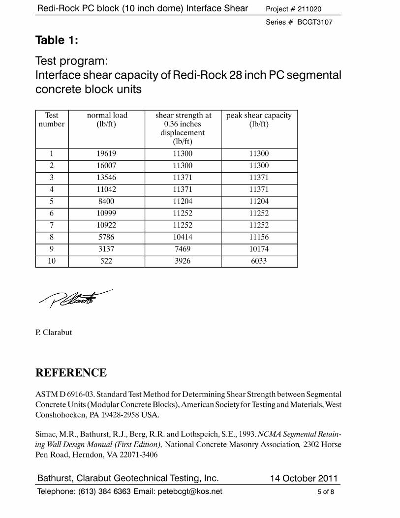
Table 1:
Test program:Interface shear capacity of Redi-Rock 28 inch PC segmentalconcrete block units
Testnumber
normal load(lb/ft)
shear strength at0.36 inchesdisplacement(lb/ft)
peak shear capacity(lb/ft)
1 19619 11300 113002 16007 11300 113003 13546 11371 113714 11042 11371 113715 8400 11204 112046 10999 11252 112527 10922 11252 112528 5786 10414 111569 3137 7469 1017410 522 3926 6033
P. Clarabut
REFERENCE
ASTMD6916-03. StandardTestMethod forDetermining Shear Strength between SegmentalConcreteUnits (ModularConcreteBlocks),AmericanSociety forTestingandMaterials,WestConshohocken, PA 19428-2958 USA.
Simac,M.R., Bathurst, R.J., Berg, R.R. and Lothspeich, S.E., 1993.NCMA Segmental Retain-ing Wall Design Manual (First Edition), National Concrete Masonry Association, 2302 HorsePen Road, Herndon, VA 22071-3406

Redi-Rock PC block (10 inch dome) Interface Shear Project # 211020
Series # BCGT3107
Bathurst, Clarabut Geotechnical Testing, Inc. 14 October 20116 of 8Telephone: (613) 384 6363 Email: [email protected]
Figure 1: Photograph of the Redi-Rock blocks in the shear testframe
Figure 2: Photograph of the Redi-Rock blocks in the shear testframe

Redi-Rock PC block (10 inch dome) Interface Shear Project # 211020
Series # BCGT3107
Bathurst, Clarabut Geotechnical Testing, Inc. 14 October 20117 of 8Telephone: (613) 384 6363 Email: [email protected]
1 Redi-Rock block 6 actuator support 11 reaction beam2 load cell 7 LVDT 12 computer controlled3 loading platen 8 2 actuators hydraulic actuator4 piston 9 loading frame5 lateral restraining system 10 spacers
7
8
12
1
3
5
9
10
1
11
6
4
4
Figure 3: Schematic of large scale shear test apparatus showingRedi-Rock 28 inch PC block units
6 m
600 mm
4 m2
7
5
Redi-Rock PC block (10 inch dome) Interface Shear Project # 211020
Series # BCGT3107
Bathurst, Clarabut Geotechnical Testing, Inc. 14 October 20118 of 8Telephone: (613) 384 6363 Email: [email protected]
0
2000
4000
6000
8000
10000
12000
0 5000 10000 15000 20000
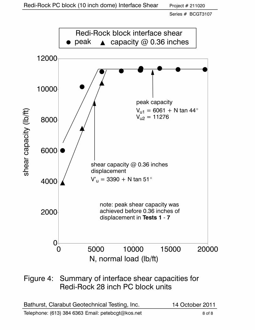
Figure 4: Summary of interface shear capacities forRedi-Rock 28 inch PC block units
Redi-Rock block interface shearpeakF
N, normal load (lb/ft)
shearcapacity(lb/ft)
shear capacity @ 0.36 inchesdisplacementV’u = 3390 + N tan 51_
peak capacityVu1 = 6061 + N tan 44_Vu2 = 11276
Y capacity @ 0.36 inches
note: peak shear capacity wasachieved before 0.36 inches ofdisplacement in Tests 1 - 7