Embed Size (px)
Citation preview
Interfacing Accessible Pedestrian Signals (APS)
with
Traffic Signal Control Equipment
David A. Noyce, PUniversity of Wisconsi
University of Massachus
Janet M. Barlow, Certified Orientation and M
Atlanta, GA
April, 2003
Source: The Seeing Eye, Inc.h.D., P.E. n – Madison etts – Amherst
C.O.M.S. obility Specialist
ABSTRACT
The primary objective of this research was to provide detailed accessible pedestrian signal
(APS) product information specifically focused on the interfacing of APS devices and traffic signal
controllers. Information on the various traffic signal controllers used today is also provided. The
information is intended for traffic engineers, traffic signal technicians, and others who are
implementing APS technologies.
This report addresses the following information:
• United States and foreign APS technologies, including those that provide mapping, speech, and location features for blind pedestrians;
• Traffic signal controller/APS interfaces, including wiring and power requirements and interaction with conflict monitoring technology;
• Lessons learned from existing installations; and
• United States traffic signal controller technologies.
Contact information for APS and traffic signal controller manufacturers is provided.
Funding for this research was provided by the U.S. Access Board. The authors would like to thank
Joseph Herr, VHB; Billie Louise Bentzen, Accessible Design for the Blind; Paul Vetter, Edwards
and Kelcey; and David Grilley, City of Portland, OR for providing information used in this report
and for their thorough, thoughtful, and timely review of the draft manuscript. Their comments and
suggestions led to many important improvements in content and description.
Interfacing Accessible Pedestrian Signals with Traffic Signal Control Equipment Page iii
TABLE OF CONTENTS ABSTRACT ......................................................................................................................................ii
TABLE OF CONTENTS .................................................................................................................... iii
INTRODUCTION.........................................................................................................................1
RESEARCH OBJECTIVES..........................................................................................................2
TRAFFIC SIGNAL CONTROLLERS .........................................................................................2
ACCESSIBLE PEDESTRIAN SIGNAL (APS) TECHNOLOGIES ...........................................3
INTERFACING APS DEVICES WITH TRAFFIC SIGNAL CONTROL EQUIPMENT..........5
LESSONS LEARNED FROM EXISTING INSTALLATIONS..................................................7
APS PRODUCTS AND MANUFACTURER INFORMATION...............................................14
Matrix of Accessible Pedestrian Signal Functions.....................................................................14
Campbell Company.....................................................................................................................15
Georgetown Electric....................................................................................................................18
Novax Industries..........................................................................................................................22
Bob Panich Consultancy .............................................................................................................25
Polara Engineering ......................................................................................................................27
Prisma Teknik..............................................................................................................................30
Relume.........................................................................................................................................34
Talking Signs...............................................................................................................................36
U.S. Traffic Corporation .............................................................................................................39
Wilcox Sales................................................................................................................................41
APS MANUFACTURER CONTACT INFORMATION...........................................................43
APPENDIX A – Traffic Signal Controllers ....................................................................................44
TRAFFIC SIGNAL CONTROL.....................................................................................................45
Evolution of Controller Standards...............................................................................................45
Typical Controller Cabinet Components.....................................................................................48
TRAFFIC SIGNAL CONTROLLER MANUFACTURERS .....................................................51
NEMA Controllers ..........................................................................................................................52
Eagle............................................................................................................................................52
Econolite......................................................................................................................................54
McCain ........................................................................................................................................56
Naztec..........................................................................................................................................57
Interfacing Accessible Pedestrian Signals with Traffic Signal Control Equipment Page iv
Peek .............................................................................................................................................59
US Traffic....................................................................................................................................61
170/179/2070 Controllers................................................................................................................63
Eagle............................................................................................................................................63
Econolite......................................................................................................................................64
McCain ........................................................................................................................................66
Naztec..........................................................................................................................................67
U.S. Traffic..................................................................................................................................68
Support Equipment..........................................................................................................................70
Naztec - MMU.............................................................................................................................70
Naztec – Conflict Monitor...........................................................................................................71
Naztec - BIU................................................................................................................................72
Naztec - Detectors .......................................................................................................................73
Traffic Signal Controller Manufacturers .........................................................................................74
APPENDIX B - References ............................................................................................................75
REFERENCES................................................................................................................................75

Interfacing Accessible Pedestrian Signals with Traffic Signal Control Equipment Page 1
INTRODUCTION
The Millennium Edition of the Manual on Uniform Traffic Control Devices was the first to
incorporate standards for accessible pedestrian signals (APS) (1). APS is defined as a device that
communicates information about pedestrian timing in a non-visual format such as audible tones, verbal
messages, and/or vibrating surfaces. Chapter 4E of the MUTCD, “Pedestrian Control Features”
includes criteria for the implementation of APS devices into existing traffic signal systems.
Information is provided on audible tones and verbal messages, vibrotactile features, pedestrian
detectors, and pushbutton locations. A task group of the Signals Technical Committee and National
Committee on Uniform Traffic Control Devices (NCUTCD) led the development of the new
provisions.
Several companies, located in the United States, Europe, and Australia, manufacture APS
products that provide information in non-visual formats. Newer technologies provide speech, location,
and mapping features at the push button; these devices have different installation requirements than the
cuckoo/chirp pedhead-mounted speakers familiar to many United States traffic engineers. New APS
devices are ambient sound responsive and may have tactile arrows, mapping, and speech information
and location features that require different sound adjustment, wiring, and installation considerations.
APS devices that make information about the status of signal phases available to visually
impaired pedestrians can provide significant benefits in usability, safety, and independence (2, 3).
Nevertheless, the recent influx of new APS products has led to some confusion concerning installation
criteria and compatibility with current U.S. traffic signal controller equipment. Additionally, several
transportation agencies that have recently installed one or more of the APS devices have reported
minor problems in their installation and operation; most have proved to be easily correctable.
Concerns with the installation of APS devices have included:
• The high voltage to the push button provided by some APS devices,
• Confusion over wiring requirements,
• Installation of two APS devices on the same pole confusing the vibrotactile information for each walk intervals,
• Controller conflicts which allow the APS to continue to provide WALK information when the traffic signal is in the flashing mode, and
April 2003
Interfacing Accessible Pedestrian Signals with Traffic Signal Control Equipment Page 2
• Installations that prevent the traffic conflict monitors (malfunction management units - MMU) from detecting errors in pedestrian information presentation or that send the traffic signals into flash due to voltage variations detected by the conflict monitor.
Although the APS devices in each case were installed with the best of intentions, installation
deficiencies can create a real safety concern for the blind pedestrian and frustration for the traffic
engineers and professionals responsible for the traffic signal system. Traffic professionals, and those
who install APS devices, need to be knowledgeable on the product features and installation
requirements to assure that all appropriate features are included and operate correctly.
RESEARCH OBJECTIVES
The primary objective of this research was to provide specifiers and installers with the
information needed for problem-free operation of APS devices. To fulfill this objective, detailed APS
and traffic signal controller product information is provided, specifically focused on the interfacing of
APS devices and traffic signal controllers. Information includes:
• Lessons learned from existing installations;
• A detailed description of available APS technologies that provide mapping, speech, and/or location features for blind pedestrians;
• Detailed information on how the APS devices interface with each traffic signal controller including:
– Wiring requirements;
– Power requirements;
– Interaction with conflict monitoring technology;
• A detailed description of traffic signal controllers (and manufacturers) currently used in the U.S. and those that may be available in the near future.
The following sections provide a description of each of the above items.
TRAFFIC SIGNAL CONTROLLERS
Control of vehicle and pedestrian movements in the U.S. via traffic signals has been in place
for over 100 years. The earliest traffic signals were manually operated, requiring a police officer or
city employee to manually “switch” traffic flow by changing red and green panels or lights in a switch
stand. As traffic continued to grow, it became obvious that mechanical/electrical signal controllers
were required to relieve police officers of their traffic control duties.
April 2003
Interfacing Accessible Pedestrian Signals with Traffic Signal Control Equipment Page 3
Electrically operated traffic signals have been in operation in the U.S. since 1914. Electric
traffic lights were first installed in Cleveland, Ohio, at Euclid Ave. and 105th Street (4). The traffic
signal consisted of two long cross-arms, red and green lights, and buzzers. Two long buzzes signaled
Euclid Avenue traffic to proceed, one long buzz meant it was 105th Street's turn to go. Note that this
signal had both a visual and audio component.
Since then, traffic signal control equipment has undergone continual improvement. The earliest
signal controllers used motors and gears to time the durations of the signal indications; some of these
controllers can still be found in use. Technology and the computer era have brought microprocessor-
based signal control equipment to what we have today, a complex yet functional system of automated
control located at more than 300,000 intersections.
Current Controller Standards Two standards are used today for traffic signal controllers (5, 6). The National Electrical
Manufacturers Association (NEMA) developed one controller standard. Two generations of the
NEMA standard are used today, namely the TS 1 (1976) and the TS 2 (1992). The TS 2 is further
divided into Type 1 and Type 2 controllers. A second standard was developed by the California
Department of Transportation (Caltrans) and the New York Department of Transportation (NYDOT).
The original standard was developed under the Type 170 platform in 1979. Updated platforms have
included the Type 179, Type 170E, and Type 2070.
Detailed information about these standards and controller features is provided in Appendix A
of this document.
ACCESSIBLE PEDESTRIAN SIGNAL (APS) TECHNOLOGIES Accessible pedestrian signals (APS) are enhancements to the traffic signal system to provide
signal phase information in audio, tactile, and/or vibrotactile formats for the pedestrian. APS devices
available today are of four general types: pedhead mounted, pushbutton integrated, vibrotactile only,
and receiver-based.
Pedhead-mounted APS are the only type that have been commonly installed in the U.S. for
the past 25 years. This type has a speaker on top of or inside the pedhead with a bell, buzzer, cheep,
cuckoo, speech message, or some other tone during the walk phase of the signal only. Some models
respond to ambient sound, becoming louder when the traffic noises are louder and quieter when the
April 2003

Interfacing Accessible Pedestrian Signals with Traffic Signal Control Equipment Page 4
traffic is quiet. They are usually intended to be heard across the street and act as a beacon, and are
relatively loud as a consequence. Manufacturers include Mallory, Novax, US Traffic, and Wilcox.
Prisma and Campbell also have an optional additional pedhead mounted speaker that can be used in
conjunction with their pushbutton integrated device.
Pushbutton-integrated APS have a speaker and a vibrating surface or arrow at the pedestrian
button. The sound comes from the pedestrian pushbutton housing, rather than the pedhead. This type
has been common in Europe and Australia for years and can be used at both actuated and fixed-time
signal timing locations. A constant quiet locator tone, repeating once per second, provides information
to the blind individual about the presence of a pedestrian pushbutton and its location. The locator tone
is intended to be audible only 2 to 4 meters (6 to 12 feet) from the pole or from the building line,
whichever is less.
The walk interval may be indicated by the same tone at a faster repetition rate (Panich, Prisma),
by a speech message (Polara, Campbell, Novax, Prisma), or by other tones (Campbell, Polara, Novax).
All devices of this type respond to ambient sound levels. These signals are intended to be loud enough
to be heard only at the beginning of the crosswalk, although volume can be increased by special
activation (Polara, Prisma, Campbell). Manufacturers include Campbell, Georgetown Electric (locator
tone not ambient sound responsive), Novax (locator tone and vibrotactile arrow combined with
pedhead speaker), Panich, Polara, and Prisma.
Vibrotactile-only APS provide only vibration at the pedestrian pushbutton. The arrow or
button vibrates when the WALK signal is on. It must be installed very precisely next to the crosswalk
to be of value, and the pedestrian must know where to look for it. Manufacturers include Campbell
and Georgetown Electric.
Receiver-based APS provide a message transmitted by infrared or LED technology from the
pedhead to a personal receiver. The pedestrian scans the intersection with the receiver to receive the
message emitted on the pedhead. These devices may also give other types of information, including
information about the name of the streets or the shape of the intersection. Manufacturers include
Relume and Talking Signs.
The section on APS devices provides details of each of the APS devices available at the time of
this report. Information was obtained from phone, e-mail, Internet, and mail contacts with
manufacturers and from the draft report, Accessible Pedestrian Signals: Synthesis and Guide to Best
Practice by Accessible Design for the Blind [www.accessforblind.org], being prepared as part of
NCHRP Project 3-62: Guidelines for Accessible Pedestrians Signals (7). A matrix summarizing
April 2003
Interfacing Accessible Pedestrian Signals with Traffic Signal Control Equipment Page 5
features provided by each device is also included.
Information about APS devices produced by the following manufacturers is included in this
publication:
• Campbell Company
• Georgetown Electric, Ltd.
• Mallory Sonalert
• Novax Industries Corporation
• Bob Panich Consultancy
• Polara Engineering
• Prisma Teknik
• Relume
• Talking Signs, Inc.
• U.S. Traffic Corporation
• Wilcox Sales For more information on intersection design to accommodate APS, consult the references and
associated web sites.
INTERFACING APS DEVICES WITH TRAFFIC SIGNAL CONTROL EQUIPMENT
APS devices work with existing traffic signal controller logic to provide the desired
information to the pedestrian. Most APS devices require no additions or activity within the traffic
signal controller cabinet for installation and operation. APS devices are designed to work with either
the green, red, WALK, or DON’T WALK indications, and to coordinate calls with the pedestrian
pushbutton. Therefore, existing wiring from the traffic signal controller to the pedestrian signal heads
and pushbuttons is maintained and unaltered. There is nothing done to the traffic signal controller
during the installation of an APS device. In most cases, the only way a traffic controller system knows
that an APS device is present is if voltage problems in the APS unit are detected by the controller’s
conflict monitor.
In most cases, the APS device is driven by the pedestrian signal head (pedhead) indications.
When electrical power is sent to the pedhead to illuminate the WALK indication, the APS device is
April 2003
Interfacing Accessible Pedestrian Signals with Traffic Signal Control Equipment Page 6
also activated. All units currently available are wired in some way to the pedestrian signal wiring.
APS devices that are pedhead-mounted provide sound only during the walk interval. These
devices are typically wired directly to the WALK indication, without other features or issues.
APS devices that are pushbutton integrated have additional control units that may be installed
(depending on the manufacturer and the device) in the pedestrian signal head (16” clamshell style,
typical) or contained completely within the pushbutton unit. At least one manufacturer also provides
control units that can be installed in the traffic controller cabinet in lieu of the pedhead. Some provide
a separate housing that must be mounted on the signal pole. Control units control operation of the
locator tone, pushbutton messages and other features available on the pushbutton integrated devices.
Pushbutton-integrated devices can also function at pretimed intersections, without pushbutton
operation.
Receiver-based devices vary depending on the type of signal. Some include a control unit
mounted in the pedhead will others include a replacement pedhead that is installed and wired as a
regular pedhead.
Wiring and Power Requirements The control units for integrated APS devices require additional wiring, most often from the
pedhead to the pushbutton. Wiring requirements are quite similar with each mounting strategy. Power
requirements are consistent with the traffic signal controller, pedhead, and pushbutton specifications
directed by NEMA. APS control units in the pedhead usually convert the 120 VAC to a lower voltage
(24 VDC) to the pushbutton. Specific wiring and power requirements are described with each APS
device later in this report.
Interaction with MMUs and Conflict Monitors The MMU, or conflict monitor, performs several functions, the most important of which is to
prevent two conflicting green indications from being illuminated. The conflict monitor is really a
voltage monitor, looking for inappropriate voltages in inappropriate locations or voltages that are
above or below desired levels. The conflict monitor will track multiple components, including the
cabinet field wiring terminals for voltage on conflicting signal indications and cabinet voltage to assure
that the proper operating range is maintained.
APS devices do not directly interact with the conflict monitor, outside of the fact that the
voltage requirements and outputs from the APS units will be monitored within the system
April 2003
Interfacing Accessible Pedestrian Signals with Traffic Signal Control Equipment Page 7
specifications. Problems with APS devices can develop when the voltage outputs exceed current
conflict monitor limits. When this happens, the conflict monitor overrides the signal control system
and places the signal into flash mode. Other problems exist when additional wiring is added from the
pedhead to the pushbutton that creates a separate circuit that is no longer detectable by the conflict
monitor. Some discussion of this problem is included in the troubleshooting described in the next
section, “Lessons Learned from Existing Installations.”
LESSONS LEARNED FROM EXISTING INSTALLATIONS Interfacing new APS devices with modern traffic signal control systems is not as problematic
as industry initially believed. Most APS devices do not interface with traffic signal controllers at all,
and those that do only provide equipment inside the cabinet. Problems experienced to date have been
minor and correctable; issues presented are not dissimilar to any device associated with traffic signal
systems. Many of the problems seem related to a lack of understanding by installers, who may not yet
be familiar with the new types of devices, wiring, and the use of the various features. Pushbutton-
integrated devices require additional wiring between the pedhead and pushbutton, more attention to
pushbutton placement and alignment, and careful adjustment of sound volumes. APS devices provide
a real benefit to all pedestrian movements at a signalized intersection. The information presented in
this section can help those who use and/or install APS devices to avoid problems.
As with any new technology, the first installation of a new type of APS device may not always
operate flawlessly. However, most are easily solvable, either by manufacturers’ adjustments to their
devices or by adjustments to the installation. Key issues discussed here include:
• APS compatibility with controller MMU/Conflict Monitor;
• Wiring to pedhead and/or controller;
• Pushbutton installation;
• Signal phasing;
• Speaker positioning and volume;
• Pushbutton and pole location;
• Tactile arrow location and position;
• Use and proper wording of speech messages; and • Braille signage and correct installation.
April 2003
Interfacing Accessible Pedestrian Signals with Traffic Signal Control Equipment Page 8
APS/Conflict Monitor Compatibility
APS compatibility with the MMU/conflict monitor is related to voltage issues. When
unexpected voltages or voltages outside of a given range are detected, the MMU overrides the
controller functions and places the signals into a flash mode until maintenance is performed. Most
problems in this area have been identified by installers; manufacturers have made modifications to
prevent such problems in the future.
Some of the APS devices manufactured internationally were designed with different voltage
standards – voltage ranges that differ from current U.S. specifications. In reducing the voltage
requirements to the pushbutton, another issue developed with one manufacturer. Some equipment was
designed to send 120 VAC to the pushbutton to provide the vibrating surface during WALK, when 24
VDC or less is desired in the US. A circuit to reduce the voltage was successfully created, but the
resultant circuit was external to the pedestrian wiring and therefore undetectable by the conflict
monitor. In this installation, the conflict monitor would not override the conflicting pedestrian signals
nor would the signals be placed into a flash mode when a pedhead malfunction occurred. The
manufacturer has developed an alternative vibrating pushbutton that operates with appropriate voltage
at the pushbutton and does not require an extra circuit.
Wiring Some problems have also been experienced with wiring and color code practices of devices
manufactured abroad. Some device manufacturers used European or Australian wire color practices
and standards. These practices are not consistent with what is commonly used in the U.S., resulting in
some wiring confusion. Although NEMA and the U.S. National Electrical Code (NEC) do not
specifically define system wire color codes, many locations have developed color requirements and
“rules-of-thumb.” Some color codes that existed in years past have been eliminated for safety reasons
assuring that technicians working with the signal wires don’t assume a wire function based on color
alone. Therefore, all wires should be tested to identify its use, regardless of color. International
companies have developed devices for U.S. installation but care should be taken to review the
instructions and wiring of the devices to assure that devices are wired properly. Installers should not
assume the function of a wire by its color.
Some of the APS devices manufactured internationally were designed with different voltage
standards – voltage ranges that differ from current U.S. specifications. Particularly, foreign devices
drew concern from signal technicians over the high voltage sent to the pushbutton location. Voltage to
April 2003
Interfacing Accessible Pedestrian Signals with Traffic Signal Control Equipment Page 9
the pushbutton was originally 120 VAC, compared to 24 VDC typical in the U.S. Technicians were
concerned about pedestrian safety if the push button is damaged or the push button is taken off by a
passing vehicle, and a pedestrian comes in contact with the live wires or electrically charged metal
pole. US models with transducers mounted in the pedestrian signal head have been developed. The
problem was resolved by placing transducers in the system to reduce the voltage from the pedhead to
the pushbutton location. Units with voltages common to U.S. installation are now being produced by
all manufacturers listed in this report.
Some problems were initially found with the controller recognizing the pedestrian pushbutton
actuation. Most pushbutton units have been found to work well with both the NEMA and 170
controllers because both (along with the conflict monitors) are sensitive to electrical deficiencies. APS
devices may be more sensitive to electrical differences than a typical pushbutton. A minor electrical
short, not affecting a standard pedestrian push button, prevented an APS installation from working
properly. The electrical short was identified and removed using common diagnostic procedures.
Pushbutton Installation Pushbuttons are often installed on the most adjacent pole to the intersection. At times, two
pushbuttons with vibrotactile outputs may be installed on the same metal pole. Vibrotactile APS
devices require insulation and a rubber gasket to eliminate vibrations generated from the other
pushbutton. Without vibratory insulation, pedestrians may not be able to determine which device has
the WALK indication since both will vibrate. Proper insulation of all pushbutton installations (or
separate poles) will prevent this problem from occurring.
Phasing A potential issue with wiring of APS devices is the conflict monitor interface, making sure the
device communicates with the traffic signal system. When traffic signals go into flash mode, the APS
device must not remain in WALK mode. This problem can be avoided by correctly wiring the APS
device into the controller/signal system so the controller logic and conflict monitor can detect and
change the pedheads to the appropriate indications.
When a phase rests in WALK, either the WALK indication continues for several minutes at a
time or a pushbutton is needed to start the tone, speech, and/or vibratory indications. If continuous, the
WALK sound can be irritating for neighbors, even at a quiet volume, so it may be preferable to have it
begin in response to actuation in residential settings. With semi-actuated phasing, a pushbutton is
April 2003
Interfacing Accessible Pedestrian Signals with Traffic Signal Control Equipment Page 10
usually not provided when crossing alongside main street traffic since the main street approach does
not have vehicular actuation. However, when the APS device is provided and the traffic signal is
coordinated or on a fixed cycle, the accessible indication will not initiate until the next cycle when the
pushbutton is pushed. Therefore, actuating the pushbutton will provide no information until the next
signal cycle is started. Pedestrians may assume the pushbutton is not working and attempt to cross
without the aid of the APS device. When the pushbutton is pushed, appropriate messaging is
recommended as a speech pushbutton information message to indicate that the signal provides a walk
interval on the next cycle. When this type of signal phasing is used, appropriate communication
between the APS device and the signal system should be evaluated.
Another scenario caused problems with pedestrian signals that rest in WALK or DON’T
WALK. A signalized intersection included a pedestrian signal to cross the side/minor street that rested
in DON'T WALK unless the pedestrian pushbutton was pushed to cross that street. This signal had
coordination and a fixed cycle. When the pushbutton was pushed, two results could occur: 1) if the
button was pushed during the side street phase, the WALK was displayed at the start of the
corresponding main street phase for a minimum time followed by the Flashing DON'T WALK and the
steady DON'T WALK; 2) if the button was pushed during the corresponding main street phase, the
WALK was displayed only if there was enough time for the WALK and Flashing DON'T WALK time
prior to the force-off period allowed by the coordination. This installation required a time period or
“window” at the beginning of the main street phase which was the only period that would allow the
WALK to come up while in that phase; otherwise, the WALK would not come up until a side street
phase started and terminated, i.e., the next signal cycle. Therefore, a pedestrian could activate the
pushbutton and not receive a timely walk interval. Again, a pedestrian may assume that the push
button is not working under this condition.
Speakers/Volume A Maryland installation experienced problems adjusting the volume of a unit that used the APS
control units installed in the controller cabinet (rather than the pedestrian signal head). Because of the
distance, the wiring was too small of a gauge to drive the speaker and provide a loud enough message,
compounded by the pole and speaker being more than 10 feet back from the crosswalk.
Manufacturer’s guidelines and specifications should be followed for proper operation. However, there
were also concerns and constraints on the amount of room for new wiring in the conduit. Speakers can
be provided for each control unit.
April 2003

Interfacing Accessible Pedestrian Signals with Traffic Signal Control Equipment Page 11
Pedhead mounted speakers in existing installations are often mounted in positions that make
the messages ambiguous. The speaker should be as close as possible to the crosswalk being signaled
by the speaker and speakers should be separated by 10 feet, if possible. For pushbutton integrated
devices, the speaker is in the pushbutton housing. The location of the pushbutton and orientation of
the speaker can be critical to hearing the WALK indication at the beginning of the crosswalk.
Although current standards call for the APS volume to be 2 to 5 dB above ambient sound and
for the locator tone to be heard from 6 to 12 feet from the pushbutton, volume is often set much louder
than that. Installers are used to devices using audible beaconing and think that APS are supposed to
loud enough to hear across the street. While the locator tone and WALK indication volume can be
measured on the street, it is difficult to get an accurate reading, because of the short duration of the
tones or messages and their response to ambient noise. Installers need to understand the distance
requirements for audibility of the locator tone and make adjustments to the devices.
Speech Messages The speech messages used for the WALK indication, as well as the descriptive pushbutton
message, must be understandable. Some problems have been reported. An example of this was found
at an intersection where the poorly recorded WALK messages made the street names indistinguishable
[“Pratt” and “Calvert”]. The recordings were made in-house and the quality of speech and accent were
poor. Digital speech messages can be downloaded from an AT&T web site and use of those may be
appropriate. Consistent wording and properly recorded messages are necessary for intelligibility in
noisy street conditions.
Speech messages have been suggested as one method to solve problems with ambiguity when
two pushbuttons were mounted on the same pole. The speech WALK message that provided the street
name was supposed to clarify that the WALK message applied to the street that the pedestrian wanted
to cross. However, if the speech message does not clarify which street the button applies to, the speech
WALK message using the street name does not clarify which street has the WALK indication to a
pedestrian who is unfamiliar with the intersection. For example, at the intersection of Harford and
Taylor Streets in Baltimore, the pushbutton message just said “Harford and Taylor” (both street names)
for all devices. The speech WALK messages said “Walk sign is on to cross Taylor” or “Walk sign is
on to cross Harford.” This didn’t resolve the ambiguity problem for users who were unfamiliar with
the intersection and not sure which street they were crossing, or who did not know which street the
pushbutton applied to.
April 2003
Interfacing Accessible Pedestrian Signals with Traffic Signal Control Equipment Page 12
Polk County, Florida wanted to use a male voice for one crossing direction and a female voice
for the other. The theory was that this difference would distinguish crossing directions and add to the
safety of the crossing. Most devices provide self-recorded messages capability; however, care should
be taken in recording messages, in terms of quality, and wording, and particularly ambiguity. Separate
poles may be the best solution.
Other minor problems relate to the recommended messages not being used; there is no standard
WALK message or standard pushbutton message. Older installations require updated messages
consistent with current MUTCD standards. Recommendations for specific wording for speech
messages were developed in January 2002 in a report on speech messages prepared by Accessible
Design for the Blind (6). Most problems can be resolved by use of wording consistent with messages
developed in that report, available online at www.accessforblind.org.
Pushbutton and Tactile Arrow Location The blind pedestrian must push the button, then line up to cross the street. Some problems
have been observed in locations of pushbuttons and poles supporting APS devices. Pushbuttons
installed without locator tones may make it impossible to determine that there is a button that must be
activated to call the WALK. Many problems exist with pole locations. Poles that are more than 10
feet from the curb line provide real problems activating the pushbutton and then realigning to cross the
street. Pushbuttons are often placed in positions that are not reachable from the sidewalk area, are in
the bushes, or behind a fence. Stub poles may be needed from some locations. Separating devices on
separate poles provides greater effectiveness.
If the original installation specification was not correct, it may limit the arrow direction and
location possibilities. The tactile arrow is supposed to point in the direction of travel on the crosswalk
and the face of the device is supposed to be parallel to the crosswalk it controls. Some installations
have the pole in a poor location, back from the street with the arrow pointing at the street and aligned
with the crosswalk direction, but not within the crosswalk area. In other locations, the arrow has
pointed a diagonal to the path that should be taken to cross the street. If installers do not understand
the arrow’s alignment, they may install it in the wrong direction, particularly if they use the holes from
the previous pushbutton.
April 2003

Interfacing Accessible Pedestrian Signals with Traffic Signal Control Equipment Page 13
Braille Signage Installation
Braille indications on the pedestrian signals have been found mounted backwards or with the
Braille label for the wrong street. Manufacturers ship them with a label to clarify positioning;
however, technicians may make adjustments to the sign and reverse or mix up the Braille plaques.
April 2003
Interfacing Accessible Pedestrian Signals with Traffic Signal Control Equipment Page 14
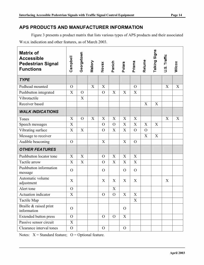
APS PRODUCTS AND MANUFACTURER INFORMATION Figure 3 presents a product matrix that lists various types of APS products and their associated
WALK indication and other features, as of March 2003.
Matrix of Accessible Pedestrian Signal Functions
TYPE
Pedhead mounted O X X O X X Pushbutton integrated X O O X X X Vibrotactile X Receiver based X X
WALK INDICATIONS
Tones X O X X X X X X X Speech messages X O O X X X X Vibrating surface X X O X X O O Message to receiver X X Audible beaconing O X X O
OTHER FEATURES
Pushbutton locator tone X X O X X X Tactile arrow X X O X X X Pushbutton information message O O O O
Automatic volume adjustment X X X X X X
Alert tone O X Actuation indicator X O O X X Tactile Map X Braille & raised print information O O
Extended button press O O O X Passive sensor circuit X Clearance interval tones O O O
Notes: X = Standard feature; O = Optional feature.
April 2003
Interfacing Accessible Pedestrian Signals with Traffic Signal Control Equipment Page 15
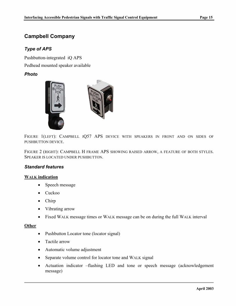
Campbell Company
Type of APS
Pushbutton-integrated iQ APS
Pedhead mounted speaker available
Photo
FIGURE 1(LEFT): CAMPBELL IQ57 APS DEVICE WITH SPEAKERS IN FRONT AND ON SIDES OF PUSHBUTTON DEVICE.
FIGURE 2 (RIGHT): CAMPBELL H FRAME APS SHOWING RAISED ARROW, A FEATURE OF BOTH STYLES. SPEAKER IS LOCATED UNDER PUSHBUTTON.
Standard features
WALK indication
• Speech message
• Cuckoo
• Chirp
• Vibrating arrow
• Fixed WALK message times or WALK message can be on during the full WALK interval
Other
• Pushbutton Locator tone (locator signal)
• Tactile arrow
• Automatic volume adjustment
• Separate volume control for locator tone and WALK signal
• Actuation indicator –flashing LED and tone or speech message (acknowledgement message)
April 2003
Interfacing Accessible Pedestrian Signals with Traffic Signal Control Equipment Page 16
Optional features
WALK indication
• Other tones as requested
• Additional pedhead-mounted speaker to provide beaconing (directed messages)
• Audible beaconing through alternating signal or far-side-only signal
Other
• Pushbutton information message (instructional message)
• Extended button press
• Braille street name
• Passive pedestrian detection
• Remote pedestrian actuation (remote activation)
• Clearance interval message
• Alert tone (WALK onset tone)
• Heater for the vibrating arrow
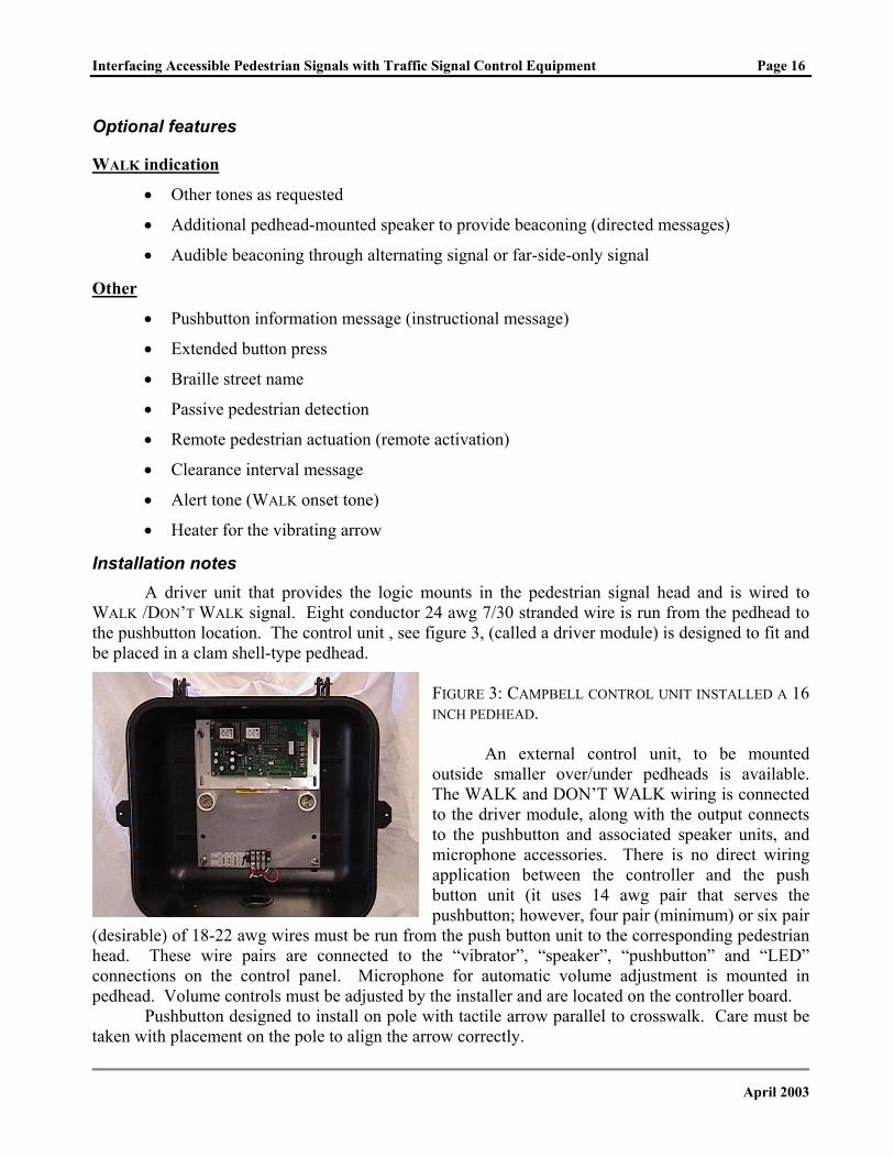
Installation notes A driver unit that provides the logic mounts in the pedestrian signal head and is wired to
WALK /DON’T WALK signal. Eight conductor 24 awg 7/30 stranded wire is run from the pedhead to the pushbutton location. The control unit , see figure 3, (called a driver module) is designed to fit and be placed in a clam shell-type pedhead.
FIGURE 3: CAMPBELL CONTROL UNIT INSTALLED A 16 INCH PEDHEAD.
An external control unit, to be mounted outside smaller over/under pedheads is available. The WALK and DON’T WALK wiring is connected to the driver module, along with the output connects to the pushbutton and associated speaker units, and microphone accessories. There is no direct wiring application between the controller and the push button unit (it uses 14 awg pair that serves the pushbutton; however, four pair (minimum) or six pair
(desirable) of 18-22 awg wires must be run from the push button unit to the corresponding pedestrian head. These wire pairs are connected to the “vibrator”, “speaker”, “pushbutton” and “LED” connections on the control panel. Microphone for automatic volume adjustment is mounted in pedhead. Volume controls must be adjusted by the installer and are located on the controller board.
Pushbutton designed to install on pole with tactile arrow parallel to crosswalk. Care must be taken with placement on the pole to align the arrow correctly.
April 2003
Interfacing Accessible Pedestrian Signals with Traffic Signal Control Equipment Page 17
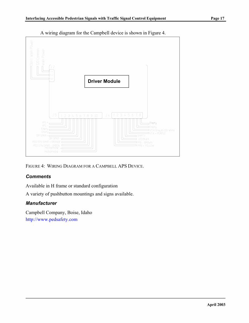
A wiring diagram for the Campbell device is shown in Figure 4.
Driver Module
FIGURE 4: WIRING DIAGRAM FOR A CAMPBELL APS DEVICE.
Comments
Available in H frame or standard configuration
A variety of pushbutton mountings and signs available.
Manufacturer
Campbell Company, Boise, Idaho http://www.pedsafety.com
April 2003
Interfacing Accessible Pedestrian Signals with Traffic Signal Control Equipment Page 18
Georgetown Electric
Type of APS
Vibrotactile-only - VIPB98
Pushbutton-integrated - VIPB99
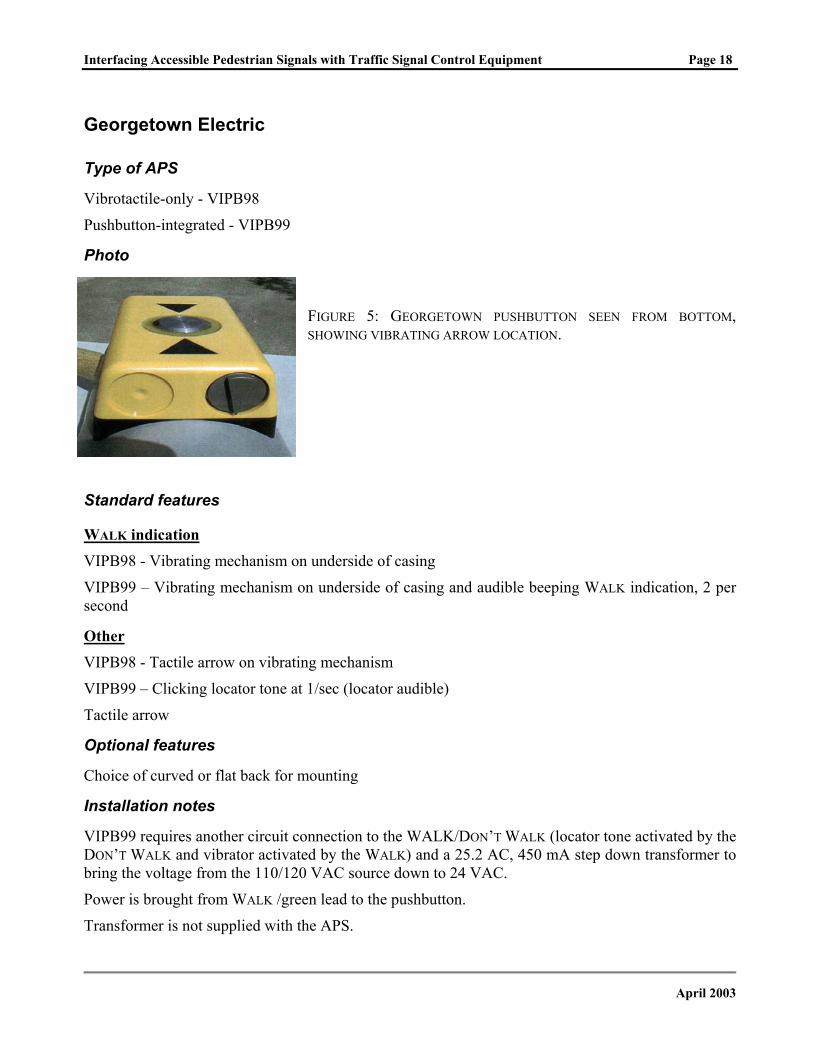
Photo
FIGURE 5: GEORGETOWN PUSHBUTTON SEEN FROM BOTTOM, SHOWING VIBRATING ARROW LOCATION.
Standard features
WALK indication VIPB98 - Vibrating mechanism on underside of casing
VIPB99 – Vibrating mechanism on underside of casing and audible beeping WALK indication, 2 per second
Other VIPB98 - Tactile arrow on vibrating mechanism
VIPB99 – Clicking locator tone at 1/sec (locator audible)
Tactile arrow
Optional features
Choice of curved or flat back for mounting
Installation notes
VIPB99 requires another circuit connection to the WALK/DON’T WALK (locator tone activated by the DON’T WALK and vibrator activated by the WALK) and a 25.2 AC, 450 mA step down transformer to bring the voltage from the 110/120 VAC source down to 24 VAC.
Power is brought from WALK /green lead to the pushbutton.
Transformer is not supplied with the APS.
April 2003
Interfacing Accessible Pedestrian Signals with Traffic Signal Control Equipment Page 19
Comments
No automatic volume adjustment. This device does not respond to ambient sound and does not comply with current MUTCD recommendations or with the Access Board’s Draft Public Rights-of-Way Accessibility Guidelines.
Pushbutton also does not meet the minimum size recommendation, of at least two inches, in the draft Public Rights-of-Way Accessibility Guidelines.
Without a locator tone, pedestrians who are blind or visually impaired may have difficulty locating and using the pushbutton.
Manufacturer
Georgetown Electric, Ltd., Wilmington, DE
April 2003
Interfacing Accessible Pedestrian Signals with Traffic Signal Control Equipment Page 20
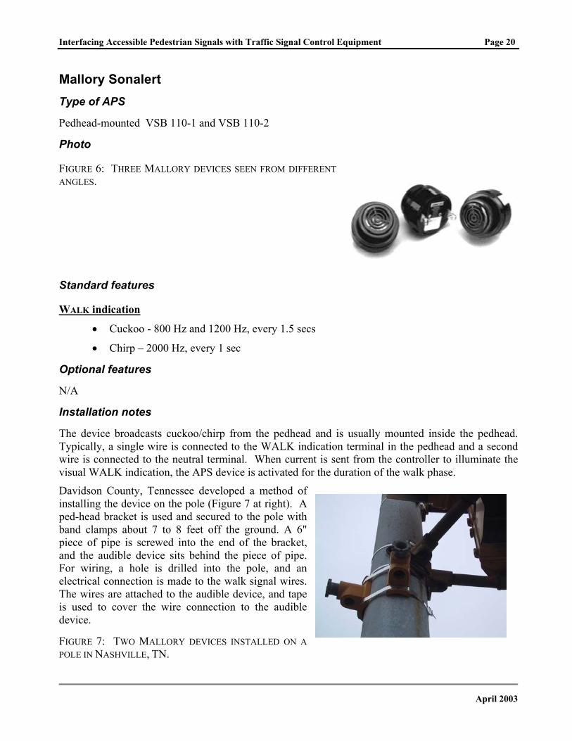
Mallory Sonalert Type of APS
Pedhead-mounted VSB 110-1 and VSB 110-2
Photo
FIGURE 6: THREE MALLORY DEVICES SEEN FROM DIFFERENT ANGLES.
Standard features
WALK indication
• Cuckoo - 800 Hz and 1200 Hz, every 1.5 secs
• Chirp – 2000 Hz, every 1 sec
Optional features
N/A
Installation notes
The device broadcasts cuckoo/chirp from the pedhead and is usually mounted inside the pedhead. Typically, a single wire is connected to the WALK indication terminal in the pedhead and a second wire is connected to the neutral terminal. When current is sent from the controller to illuminate the visual WALK indication, the APS device is activated for the duration of the walk phase.
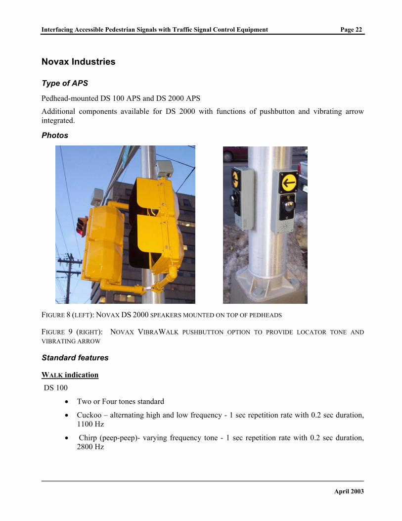
Davidson County, Tennessee developed a method of installing the device on the pole (Figure 7 at right). A ped-head bracket is used and secured to the pole with band clamps about 7 to 8 feet off the ground. A 6" piece of pipe is screwed into the end of the bracket, and the audible device sits behind the piece of pipe. For wiring, a hole is drilled into the pole, and an electrical connection is made to the walk signal wires. The wires are attached to the audible device, and tape is used to cover the wire connection to the audible device.
FIGURE 7: TWO MALLORY DEVICES INSTALLED ON A POLE IN NASHVILLE, TN.
April 2003
Interfacing Accessible Pedestrian Signals with Traffic Signal Control Equipment Page 21
Comments
No automatic volume adjustment. This device does not respond to ambient sound and does not comply with current MUTCD recommendations or with the Access Board’s Draft Public Rights-of-Way Accessibility Guidelines.
Without a locator tone, pedestrians who are blind or visually impaired may have difficulty locating and using the pushbutton.
Mallory also sells sound generators in various beeps, siren and chime sounds; these are not recommended sounds for use as APS
Manufacturer
Mallory Sonalert Products, Inc., Indianapolis, IN
http://www.mallory-sonalert.com
April 2003
Interfacing Accessible Pedestrian Signals with Traffic Signal Control Equipment Page 22
Novax Industries
Type of APS
Pedhead-mounted DS 100 APS and DS 2000 APS
Additional components available for DS 2000 with functions of pushbutton and vibrating arrow integrated.
Photos
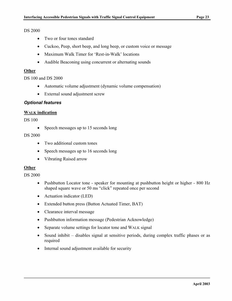
FIGURE 8 (LEFT): NOVAX DS 2000 SPEAKERS MOUNTED ON TOP OF PEDHEADS
FIGURE 9 (RIGHT): NOVAX VIBRAWALK PUSHBUTTON OPTION TO PROVIDE LOCATOR TONE AND VIBRATING ARROW
Standard features
WALK indication DS 100
• Two or Four tones standard
• Cuckoo – alternating high and low frequency - 1 sec repetition rate with 0.2 sec duration, 1100 Hz
• Chirp (peep-peep)- varying frequency tone - 1 sec repetition rate with 0.2 sec duration, 2800 Hz
April 2003
Interfacing Accessible Pedestrian Signals with Traffic Signal Control Equipment Page 23
DS 2000
• Two or four tones standard
• Cuckoo, Peep, short beep, and long beep, or custom voice or message
• Maximum Walk Timer for ‘Rest-in-Walk’ locations
• Audible Beaconing using concurrent or alternating sounds
Other DS 100 and DS 2000
• Automatic volume adjustment (dynamic volume compensation)
• External sound adjustment screw
Optional features
WALK indication DS 100
• Speech messages up to 15 seconds long
DS 2000
• Two additional custom tones
• Speech messages up to 16 seconds long
• Vibrating Raised arrow
Other DS 2000
• Pushbutton Locator tone - speaker for mounting at pushbutton height or higher - 800 Hz shaped square wave or 50 ms “click” repeated once per second
• Actuation indicator (LED)
• Extended button press (Button Actuated Timer, BAT)
• Clearance interval message
• Pushbutton information message (Pedestrian Acknowledge)
• Separate volume settings for locator tone and WALK signal
• Sound inhibit – disables signal at sensitive periods, during complex traffic phases or as required
• Internal sound adjustment available for security
April 2003
Interfacing Accessible Pedestrian Signals with Traffic Signal Control Equipment Page 24
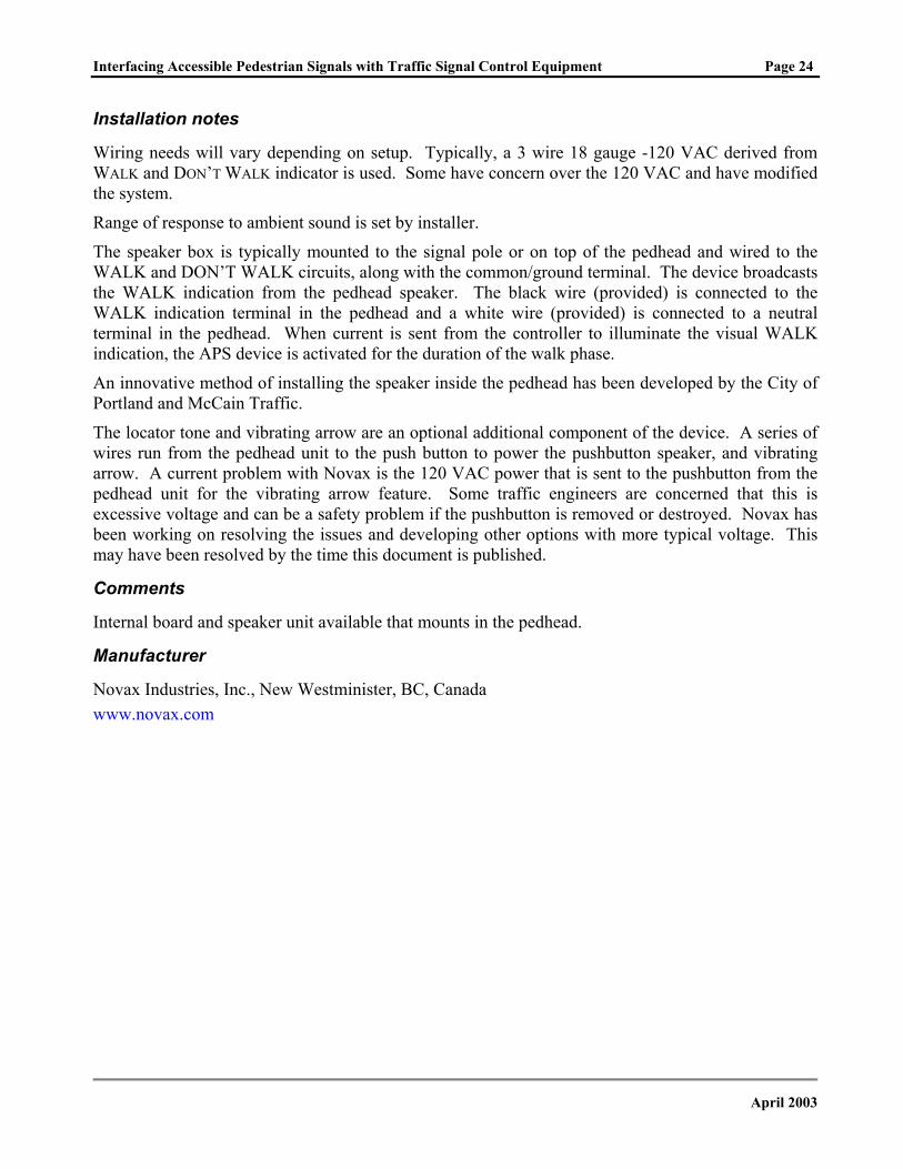
Installation notes
Wiring needs will vary depending on setup. Typically, a 3 wire 18 gauge -120 VAC derived from WALK and DON’T WALK indicator is used. Some have concern over the 120 VAC and have modified the system.
Range of response to ambient sound is set by installer.
The speaker box is typically mounted to the signal pole or on top of the pedhead and wired to the WALK and DON’T WALK circuits, along with the common/ground terminal. The device broadcasts the WALK indication from the pedhead speaker. The black wire (provided) is connected to the WALK indication terminal in the pedhead and a white wire (provided) is connected to a neutral terminal in the pedhead. When current is sent from the controller to illuminate the visual WALK indication, the APS device is activated for the duration of the walk phase.
An innovative method of installing the speaker inside the pedhead has been developed by the City of Portland and McCain Traffic.
The locator tone and vibrating arrow are an optional additional component of the device. A series of wires run from the pedhead unit to the push button to power the pushbutton speaker, and vibrating arrow. A current problem with Novax is the 120 VAC power that is sent to the pushbutton from the pedhead unit for the vibrating arrow feature. Some traffic engineers are concerned that this is excessive voltage and can be a safety problem if the pushbutton is removed or destroyed. Novax has been working on resolving the issues and developing other options with more typical voltage. This may have been resolved by the time this document is published.
Comments
Internal board and speaker unit available that mounts in the pedhead.
Manufacturer
Novax Industries, Inc., New Westminister, BC, Canada www.novax.com
April 2003
Interfacing Accessible Pedestrian Signals with Traffic Signal Control Equipment Page 25
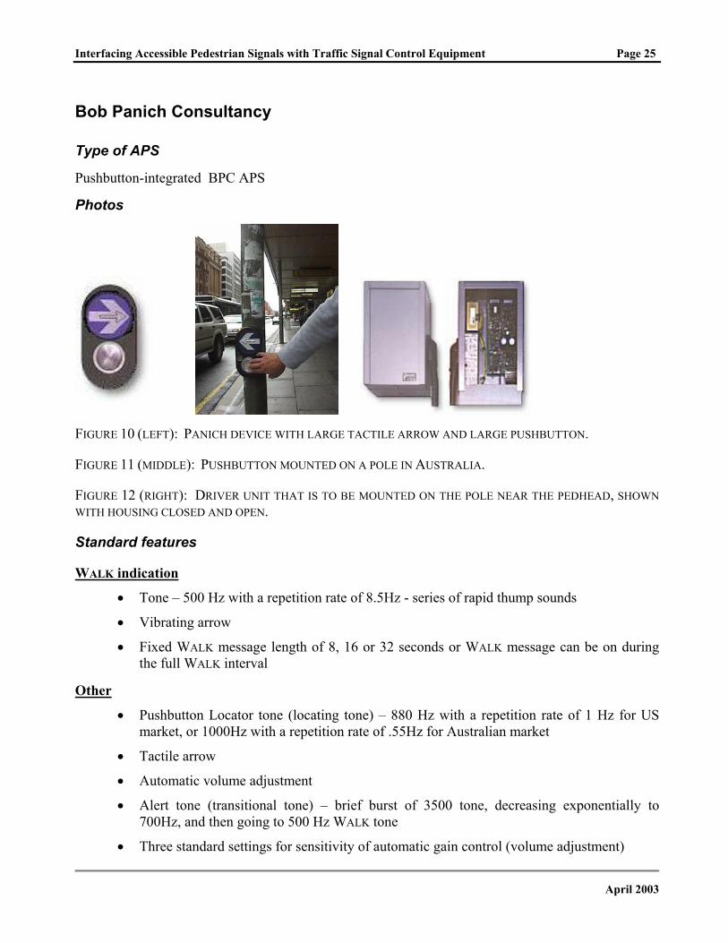
Bob Panich Consultancy
Type of APS
Pushbutton-integrated BPC APS
Photos
FIGURE 10 (LEFT): PANICH DEVICE WITH LARGE TACTILE ARROW AND LARGE PUSHBUTTON.
FIGURE 11 (MIDDLE): PUSHBUTTON MOUNTED ON A POLE IN AUSTRALIA.
FIGURE 12 (RIGHT): DRIVER UNIT THAT IS TO BE MOUNTED ON THE POLE NEAR THE PEDHEAD, SHOWN WITH HOUSING CLOSED AND OPEN.
Standard features
WALK indication
• Tone – 500 Hz with a repetition rate of 8.5Hz - series of rapid thump sounds
• Vibrating arrow
• Fixed WALK message length of 8, 16 or 32 seconds or WALK message can be on during the full WALK interval
Other
• Pushbutton Locator tone (locating tone) – 880 Hz with a repetition rate of 1 Hz for US market, or 1000Hz with a repetition rate of .55Hz for Australian market
• Tactile arrow
• Automatic volume adjustment
• Alert tone (transitional tone) – brief burst of 3500 tone, decreasing exponentially to 700Hz, and then going to 500 Hz WALK tone
• Three standard settings for sensitivity of automatic gain control (volume adjustment)
April 2003
Interfacing Accessible Pedestrian Signals with Traffic Signal Control Equipment Page 26
Optional features
WALK indication
• Cuckoo and chirp or other sounds
• Speech message as WALK indication
Other
• Actuation indicator (demand indicator/demand tone) - light and tone
• Extended button press – allows pedestrians to request a WALK tone at 12 dB above the sound of the locator tone (Higher volume demand, HVD)
Installation notes
The pushbutton assembly is connected to the pushbutton wire pair to the controller. The APS control unit, called driver module in the manufacturer’s information, is mounted in a housing on the pole near the pedhead and wired to the pedhead. A second wire pair is run to the driver module on the pole. The module is wired to the WALK indication and is activated with the voltage to the pedhead. Manufacturers specifications should be consulted for other wiring requirements that are specific to each setup.
Automatic gain control, the level of the tone in response to ambient noise, is set during installation.
Pushbutton designed to install on pole with tactile arrow parallel to crosswalk. Care must be taken with placement on the pole to align the arrow correctly.
Comments Complies with specifications of the Australian standard; standard pushbutton in Australia. Manufacturer states that they will provide other features as needed.
Manufacturer
Bob Panich Consultancy Pty. Ltd., Ryde, New South Wales, Australia
http://www.bobpanich.com.au
April 2003
Interfacing Accessible Pedestrian Signals with Traffic Signal Control Equipment Page 27
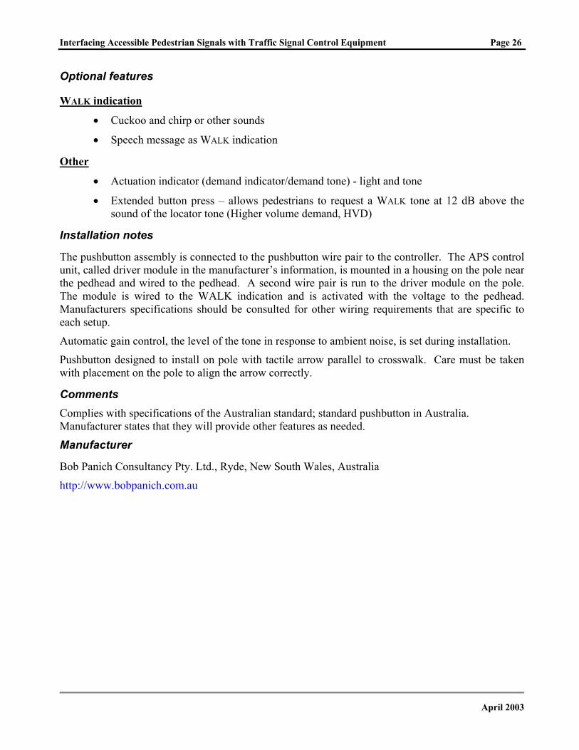
Polara Engineering
Type of APS
Pushbutton-integrated Navigator APS
Photos
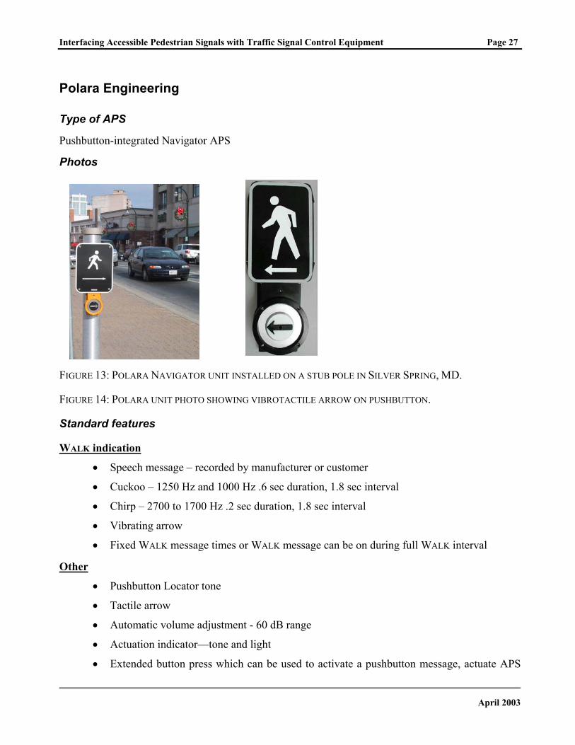
FIGURE 13: POLARA NAVIGATOR UNIT INSTALLED ON A STUB POLE IN SILVER SPRING, MD.
FIGURE 14: POLARA UNIT PHOTO SHOWING VIBROTACTILE ARROW ON PUSHBUTTON.
Standard features
WALK indication
• Speech message – recorded by manufacturer or customer
• Cuckoo – 1250 Hz and 1000 Hz .6 sec duration, 1.8 sec interval
• Chirp – 2700 to 1700 Hz .2 sec duration, 1.8 sec interval
• Vibrating arrow
• Fixed WALK message times or WALK message can be on during full WALK interval
Other
• Pushbutton Locator tone
• Tactile arrow
• Automatic volume adjustment - 60 dB range
• Actuation indicator—tone and light
• Extended button press which can be used to activate a pushbutton message, actuate APS
April 2003
Interfacing Accessible Pedestrian Signals with Traffic Signal Control Equipment Page 28
or request a louder Walk signal and locator tone for subsequent clearance interval
Optional features
WALK indication
• WALK tones or speech messages as requested
Other
• Pushbutton information message (voice on location)
• Braille street name on the face plate
• Face plate with informational sign
Installation notes
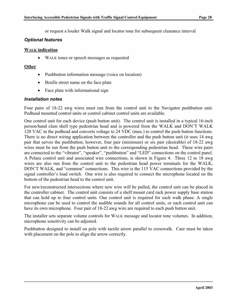
Four pairs of 18-22 awg wires must run from the control unit to the Navigator pushbutton unit. Pedhead mounted control units or control cabinet control units are available.
One control unit for each device (push button unit). The control unit is installed in a typical 16-inch person/hand clam shell type pedestrian head and is powered from the WALK and DON’T WALK 120 VAC in the pedhead and converts voltage to 24 VDC (max.) to control the push button functions. There is no direct wiring application between the controller and the push button unit (it uses 14 awg pair that serves the pushbutton; however, four pair (minimum) or six pair (desirable) of 18-22 awg wires must be run from the push button unit to the corresponding pedestrian head. These wire pairs are connected to the “vibrator”, “speaker”, “pushbutton” and “LED” connections on the control panel. A Polara control unit and associated wire connections, is shown in Figure 4. Three 12 to 18 awg wires are also run from the control unit to the pedestrian head power terminals for the WALK, DON’T WALK, and “common” connections. This wire is the 115 VAC connections provided by the signal controller’s load switch. One wire is also required to connect the microphone located on the bottom of the pedestrian head to the control unit.
For new/reconstructed intersections where new wire will be pulled, the control unit can be placed in the controller cabinet. The control unit consists of a shelf mount card rack power supply base station that can hold up to four control units. One control unit is required for each walk phase. A single microphone can be used to control the audible sounds for all control units, or each control unit can have its own microphone. Four pair of 18-22 awg wire are required to each push button unit.
The installer sets separate volume controls for WALK message and locator tone volumes. In addition, microphone sensitivity can be adjusted.
Pushbutton designed to install on pole with tactile arrow parallel to crosswalk. Care must be taken with placement on the pole to align the arrow correctly.
April 2003
Interfacing Accessible Pedestrian Signals with Traffic Signal Control Equipment Page 29
FIGURE 15: POLARA CONTROL UNIT WIRING DIAGRAM.
Comments Manufacturer is developing a model that operates with only two wires to the pushbutton and is
programmable after installation by a traffic engineer using a handheld PDA type device. The new model will have the capability to alternate signal sounds, to countdown pedestrian clearance interval and present a signal at the far end of the crosswalk only. It is expected to be available by fall 2003.
Manufacturer
Polara Engineering, Fullerton, CA http://www.polara.com
April 2003
Interfacing Accessible Pedestrian Signals with Traffic Signal Control Equipment Page 30
Prisma Teknik
Type of APS
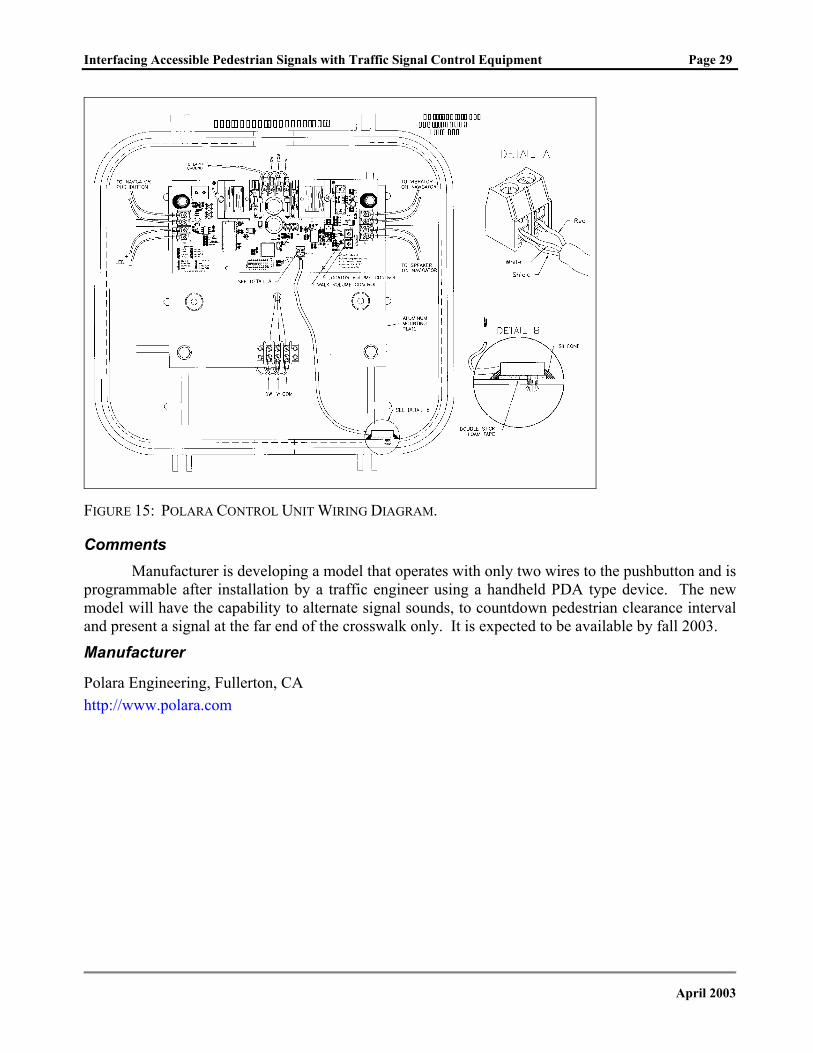
Pushbutton-integrated: Several models with different standard features, TS-907, TS-903F, TS-904, TS-908
Additional pedhead mounted directional speaker, TS-995, available
Photos
FIGURE 16: DIAGRAM SHOWING DIFFERENT COMPONENTS INSIDE THE PUSHBUTTON UNIT.
FIGURE 17: PRISMA APS MOUNTED ON A POLE IN DENMARK.
Standard features
WALK indication
• Ten different tones possible - same tone as locator tone at rapid rate of 10 repetitions per second
Other
• Pushbutton Locator tone, 10 different tones available
• Tactile arrow
• Automatic volume adjustment within range of 55- 95 dB
April 2003
Interfacing Accessible Pedestrian Signals with Traffic Signal Control Equipment Page 31
• Actuation indicator - light and tone
• Crosswalk tactile map (Braille map)
• Fault indicator
Optional features
WALK indication
• Vibrating button or arrow on bottom or top of device
• Speech WALK message
• Additional directional speaker for mounting at overhead location
Other
• Pushbutton Information Message 1- 16 seconds
• Night switch
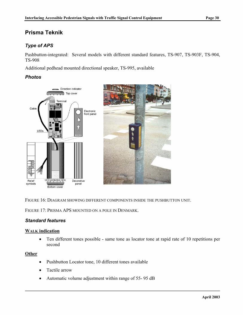
Crosswalk tactile map
The crosswalk tactile map is a standard features of the Prismatek device. Symbols are standardized in Sweden.
FIGURE 18 AND 19: CHART SHOWING THE SELECTION OF STANDARD SYMBOLS SUPPLIED WITH THE PRISMA APS.
FIGURE 20: PHOTO OF PRISMA INSTALLED ON THE STREET WITH PEDESTRIAN USING TACTILE MAP.
April 2003
Interfacing Accessible Pedestrian Signals with Traffic Signal Control Equipment Page 32
Installation notes
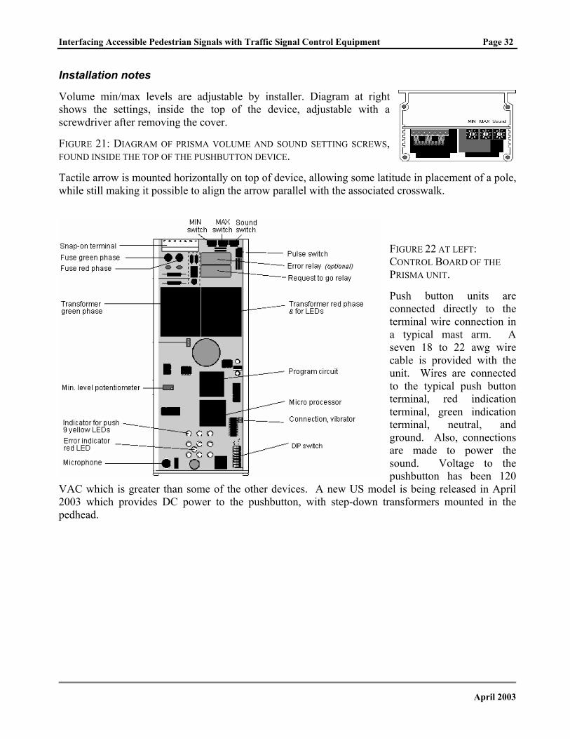
Volume min/max levels are adjustable by installer. Diagram at right shows the settings, inside the top of the device, adjustable with a screwdriver after removing the cover.
FIGURE 21: DIAGRAM OF PRISMA VOLUME AND SOUND SETTING SCREWS, FOUND INSIDE THE TOP OF THE PUSHBUTTON DEVICE.
Tactile arrow is mounted horizontally on top of device, allowing some latitude in placement of a pole, while still making it possible to align the arrow parallel with the associated crosswalk.
FIGURE 22 AT LEFT: CONTROL BOARD OF THE PRISMA UNIT.
Push button units are connected directly to the terminal wire connection in a typical mast arm. A seven 18 to 22 awg wire cable is provided with the unit. Wires are connected to the typical push button terminal, red indication terminal, green indication terminal, neutral, and ground. Also, connections are made to power the sound. Voltage to the pushbutton has been 120
VAC which is greater than some of the other devices. A new US model is being released in April 2003 which provides DC power to the pushbutton, with step-down transformers mounted in the pedhead.
April 2003
Interfacing Accessible Pedestrian Signals with Traffic Signal Control Equipment Page 33
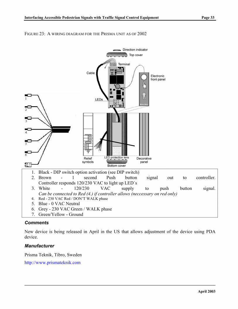
FIGURE 23: A WIRING DIAGRAM FOR THE PRISMA UNIT AS OF 2002
1. Black - DIP switch option activation (see DIP switch) 2. Brown - 1 second Push button signal out to controller.
Controller responds 120/230 VAC to light up LED´s 3. White - 120/230 VAC supply to push button signal.
Can be connected to Red (4.) if controller allows (neccessary on red only) 4. Red - 230 VAC Red / DON’T WALK phase 5. Blue - 0 VAC Neutral 6. Grey - 230 VAC Green / WALK phase 7. Green/Yellow - Ground
Comments
New device is being released in April in the US that allows adjustment of the device using PDA device.
Manufacturer
Prisma Teknik, Tibro, Sweden
http://www.prismateknik.com
April 2003
Interfacing Accessible Pedestrian Signals with Traffic Signal Control Equipment Page 34
Relume
Type of APS
Receiver-based
Photos
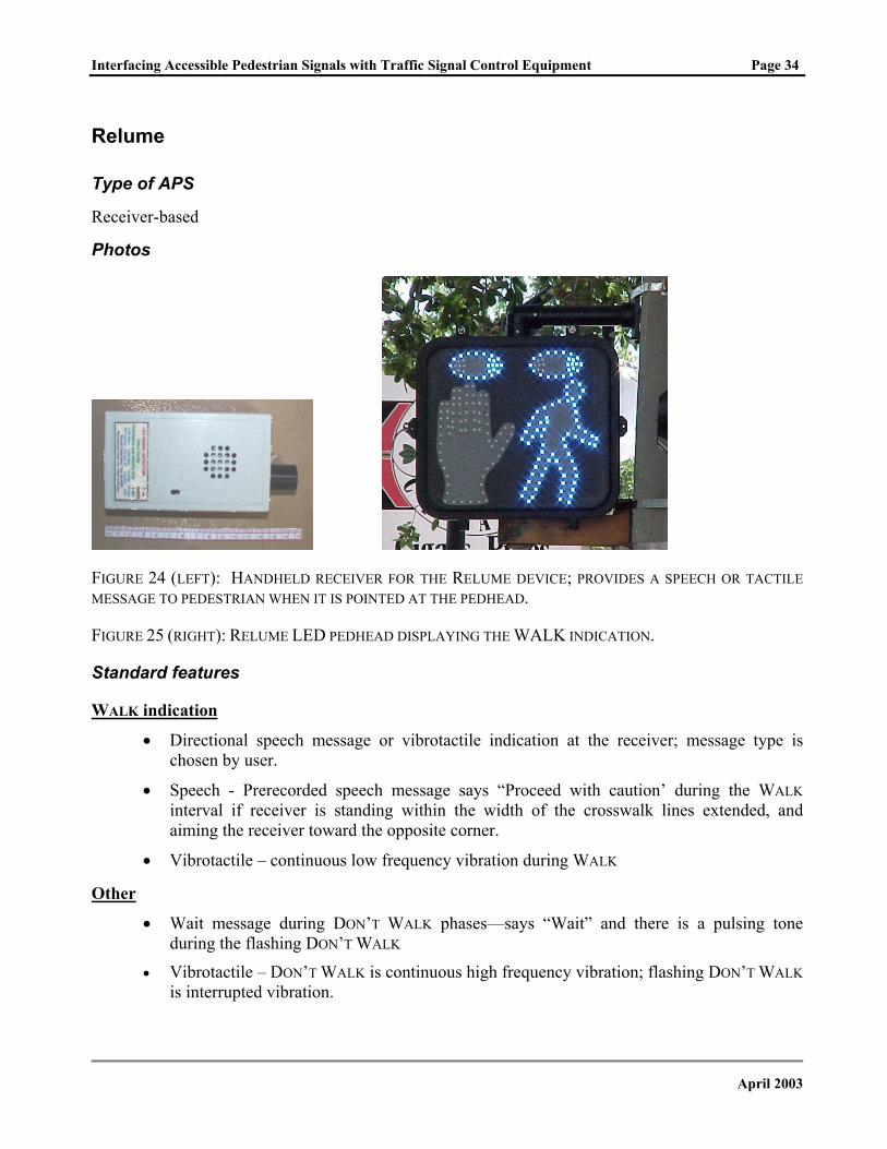
FIGURE 24 (LEFT): HANDHELD RECEIVER FOR THE RELUME DEVICE; PROVIDES A SPEECH OR TACTILE MESSAGE TO PEDESTRIAN WHEN IT IS POINTED AT THE PEDHEAD.
FIGURE 25 (RIGHT): RELUME LED PEDHEAD DISPLAYING THE WALK INDICATION.
Standard features
WALK indication
• Directional speech message or vibrotactile indication at the receiver; message type is chosen by user.
• Speech - Prerecorded speech message says “Proceed with caution’ during the WALK interval if receiver is standing within the width of the crosswalk lines extended, and aiming the receiver toward the opposite corner.
• Vibrotactile – continuous low frequency vibration during WALK
Other
• Wait message during DON’T WALK phases—says “Wait” and there is a pulsing tone during the flashing DON’T WALK
• Vibrotactile – DON’T WALK is continuous high frequency vibration; flashing DON’T WALK is interrupted vibration.
April 2003

Interfacing Accessible Pedestrian Signals with Traffic Signal Control Equipment Page 35
Optional features
N/A
Installation notes
Pedestrian signal heads must be Relume LED heads. Speech message recorded in personal receiver is triggered by pulsed light from the Relume LED pedestrian signal display. The pedhead must be carefully positioned to transmit information only within the width of the crosswalk.
Relume devices are simply replacements LED pedheads with typical wiring. However, concerns have been raised about how to provide access to the information to pedestrians who are blind who do not have receivers and do not know where the Relume devices are located.
Comments
Speech message during WALK is not in language specified in MUTCD.
Device has an approximately 15 degree field to pick up signal.
Pedestrians who are blind must have access to receivers.
Pedestrians must know where the Relume pedheads are installed, or they are unlikely to search for or use the available information.
Without a locator tone, pedestrians who are blind or visually impaired may have difficulty locating and using the pushbutton.
Manufacturer
Relume Corporation, Troy, MI
http://www.relume.com
April 2003
Interfacing Accessible Pedestrian Signals with Traffic Signal Control Equipment Page 36
Talking Signs
Type of APS
Receiver-based
Photos
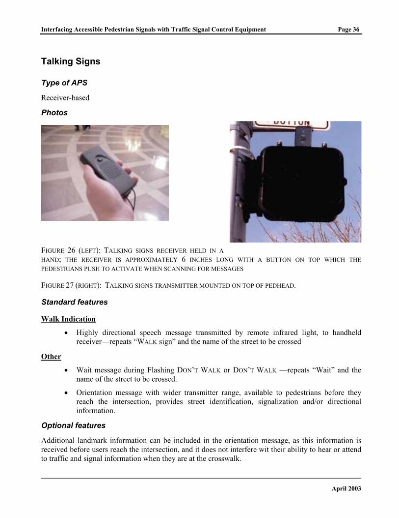
FIGURE 26 (LEFT): TALKING SIGNS RECEIVER HELD IN A HAND; THE RECEIVER IS APPROXIMATELY 6 INCHES LONG WITH A BUTTON ON TOP WHICH THE PEDESTRIANS PUSH TO ACTIVATE WHEN SCANNING FOR MESSAGES
FIGURE 27 (RIGHT): TALKING SIGNS TRANSMITTER MOUNTED ON TOP OF PEDHEAD.
Standard features
Walk Indication
• Highly directional speech message transmitted by remote infrared light, to handheld receiver—repeats “WALK sign” and the name of the street to be crossed
Other
• Wait message during Flashing DON’T WALK or DON’T WALK —repeats “Wait” and the name of the street to be crossed.
• Orientation message with wider transmitter range, available to pedestrians before they reach the intersection, provides street identification, signalization and/or directional information.
Optional features
Additional landmark information can be included in the orientation message, as this information is received before users reach the intersection, and it does not interfere wit their ability to hear or attend to traffic and signal information when they are at the crosswalk.
April 2003
Interfacing Accessible Pedestrian Signals with Traffic Signal Control Equipment Page 37
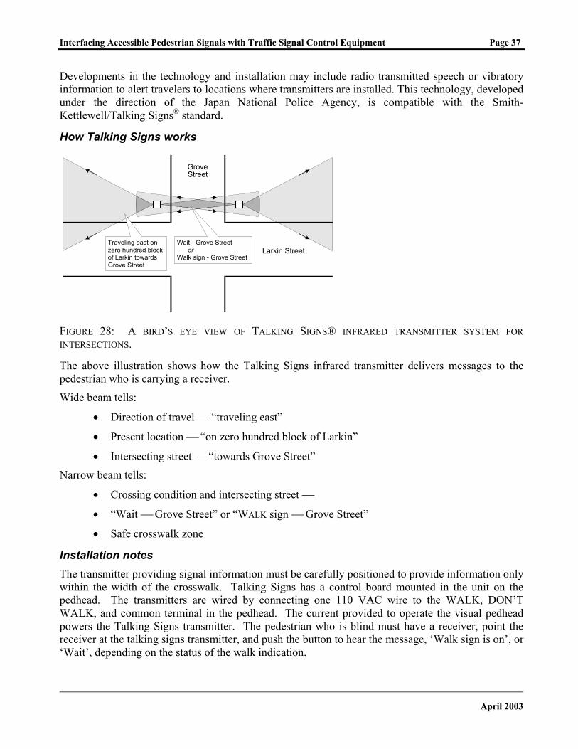
Developments in the technology and installation may include radio transmitted speech or vibratory information to alert travelers to locations where transmitters are installed. This technology, developed under the direction of the Japan National Police Agency, is compatible with the Smith-Kettlewell/Talking Signs® standard.
How Talking Signs works
GroveStreet
Larkin StreetTraveling east onzero hundred blockof Larkin towardsGrove Street
Wait - Grove Street orWalk sign - Grove Street
FIGURE 28: A BIRD’S EYE VIEW OF TALKING SIGNS® INFRARED TRANSMITTER SYSTEM FOR INTERSECTIONS.
The above illustration shows how the Talking Signs infrared transmitter delivers messages to the pedestrian who is carrying a receiver.
Wide beam tells:
• Direction of travel “traveling east”
• Present location “on zero hundred block of Larkin”
• Intersecting street “towards Grove Street”
Narrow beam tells:
• Crossing condition and intersecting street
• “Wait Grove Street” or “WALK sign Grove Street”
• Safe crosswalk zone
Installation notes The transmitter providing signal information must be carefully positioned to provide information only within the width of the crosswalk. Talking Signs has a control board mounted in the unit on the pedhead. The transmitters are wired by connecting one 110 VAC wire to the WALK, DON’T WALK, and common terminal in the pedhead. The current provided to operate the visual pedhead powers the Talking Signs transmitter. The pedestrian who is blind must have a receiver, point the receiver at the talking signs transmitter, and push the button to hear the message, ‘Walk sign is on’, or ‘Wait’, depending on the status of the walk indication.
April 2003
Interfacing Accessible Pedestrian Signals with Traffic Signal Control Equipment Page 38
Comments
Infinitely variable messages recorded in transmitters.
Receivers usable for many wayfinding tasks where transmitters are installed.
Pedestrians must know where the TS transmitters are installed, or they are unlikely to search for or use the available information.
Pedestrians who are blind must have access to receivers.
Infrared beams can be difficult to detect in some weather conditions.
Manufacturer
Talking Signs Inc., Baton Rouge, LA
http://www.talkingsigns.com
April 2003
Interfacing Accessible Pedestrian Signals with Traffic Signal Control Equipment Page 39
U.S. Traffic Corporation
Type of APS
Pedhead-mounted APS 10 -
Photos
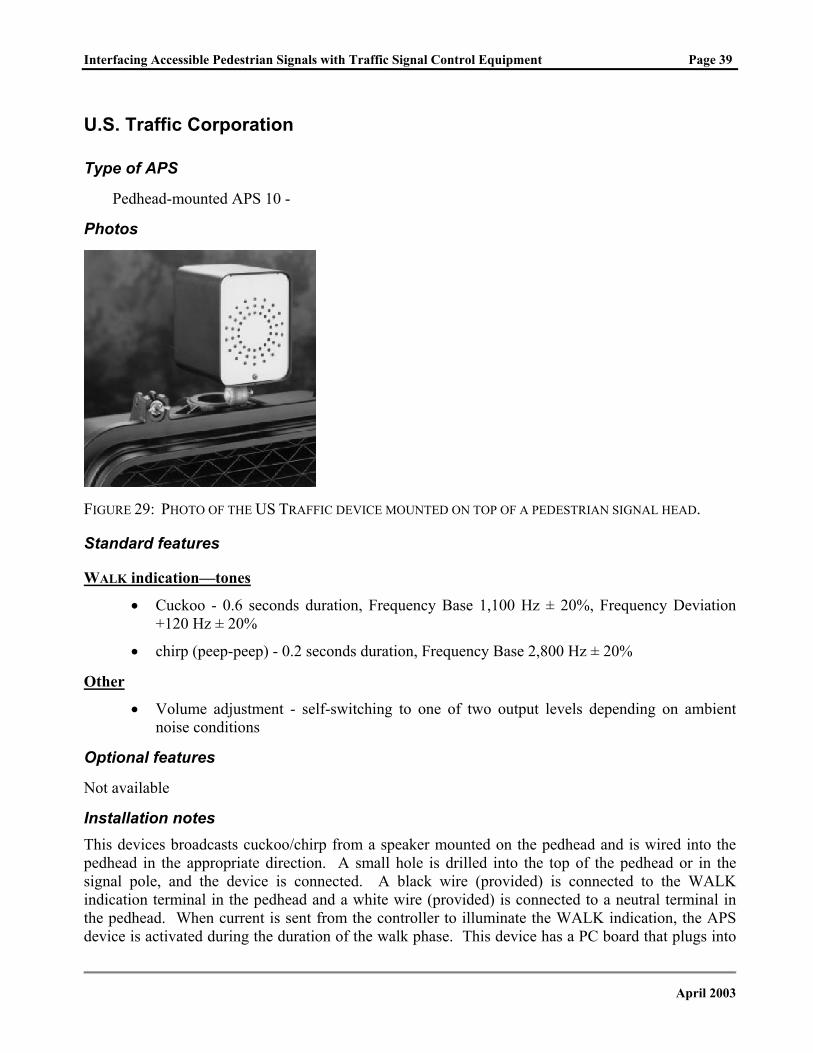
FIGURE 29: PHOTO OF THE US TRAFFIC DEVICE MOUNTED ON TOP OF A PEDESTRIAN SIGNAL HEAD.
Standard features
WALK indication—tones
• Cuckoo - 0.6 seconds duration, Frequency Base 1,100 Hz ± 20%, Frequency Deviation +120 Hz ± 20%
• chirp (peep-peep) - 0.2 seconds duration, Frequency Base 2,800 Hz ± 20%
Other
• Volume adjustment - self-switching to one of two output levels depending on ambient noise conditions
Optional features
Not available
Installation notes This devices broadcasts cuckoo/chirp from a speaker mounted on the pedhead and is wired into the pedhead in the appropriate direction. A small hole is drilled into the top of the pedhead or in the signal pole, and the device is connected. A black wire (provided) is connected to the WALK indication terminal in the pedhead and a white wire (provided) is connected to a neutral terminal in the pedhead. When current is sent from the controller to illuminate the WALK indication, the APS device is activated during the duration of the walk phase. This device has a PC board that plugs into
April 2003
Interfacing Accessible Pedestrian Signals with Traffic Signal Control Equipment Page 40
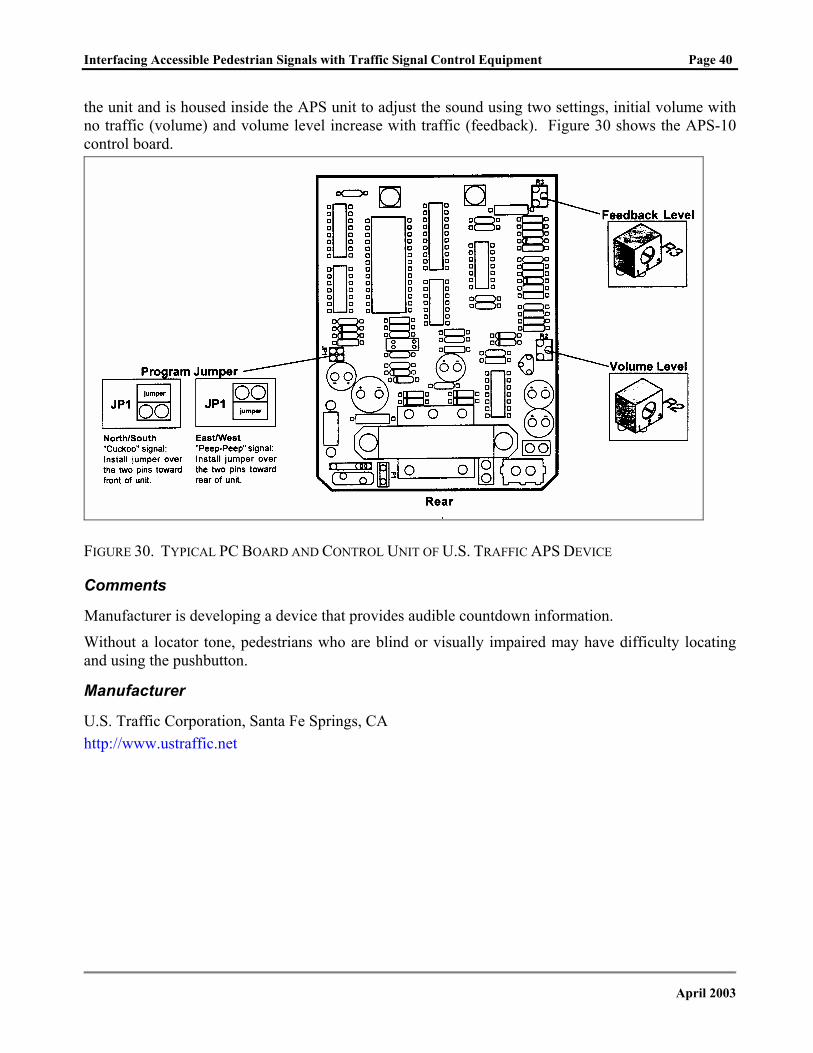
the unit and is housed inside the APS unit to adjust the sound using two settings, initial volume with no traffic (volume) and volume level increase with traffic (feedback). Figure 30 shows the APS-10 control board.
FIGURE 30. TYPICAL PC BOARD AND CONTROL UNIT OF U.S. TRAFFIC APS DEVICE
Comments
Manufacturer is developing a device that provides audible countdown information.
Without a locator tone, pedestrians who are blind or visually impaired may have difficulty locating and using the pushbutton.
Manufacturer
U.S. Traffic Corporation, Santa Fe Springs, CA http://www.ustraffic.net
April 2003
Interfacing Accessible Pedestrian Signals with Traffic Signal Control Equipment Page 41
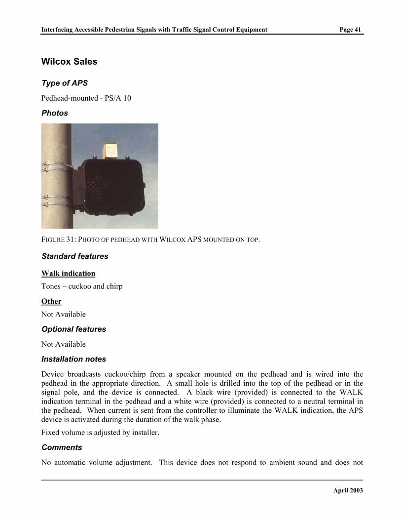
Wilcox Sales
Type of APS
Pedhead-mounted - PS/A 10
Photos
FIGURE 31: PHOTO OF PEDHEAD WITH WILCOX APS MOUNTED ON TOP.
Standard features
Walk indication Tones – cuckoo and chirp
Other Not Available
Optional features
Not Available
Installation notes
Device broadcasts cuckoo/chirp from a speaker mounted on the pedhead and is wired into the pedhead in the appropriate direction. A small hole is drilled into the top of the pedhead or in the signal pole, and the device is connected. A black wire (provided) is connected to the WALK indication terminal in the pedhead and a white wire (provided) is connected to a neutral terminal in the pedhead. When current is sent from the controller to illuminate the WALK indication, the APS device is activated during the duration of the walk phase.
Fixed volume is adjusted by installer.
Comments
No automatic volume adjustment. This device does not respond to ambient sound and does not
April 2003
Interfacing Accessible Pedestrian Signals with Traffic Signal Control Equipment Page 42
comply with current MUTCD recommendations or with the Access Board’s Draft Public Rights-of-Way Accessibility Guidelines.
Without a locator tone, pedestrians who are blind or visually impaired may have difficulty locating and using the pushbutton.
Wilcox is also developing an audible sign using same speaker technology.
Manufacturer
Wilcox Sales Company, Claremont, CA http://www.wilcoxsales.com
April 2003
Interfacing Accessible Pedestrian Signals with Traffic Signal Control Equipment Page 43
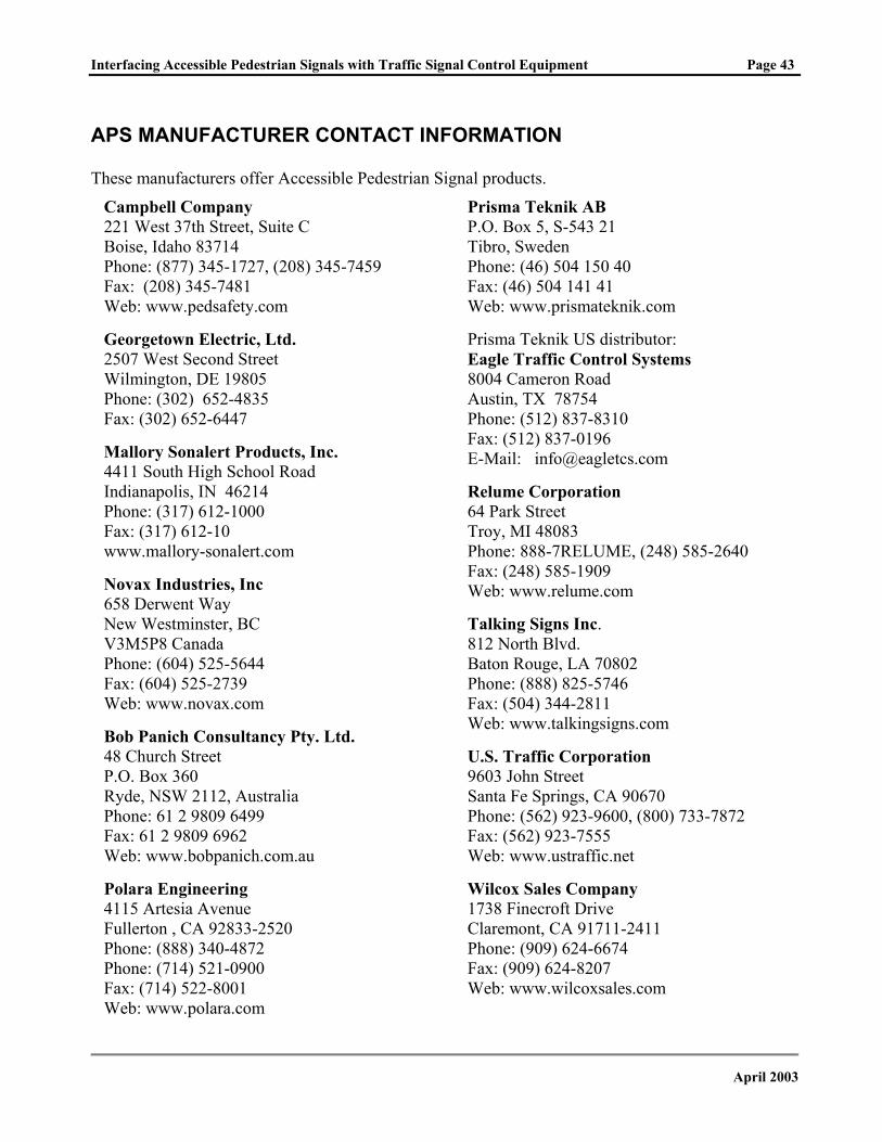
APS MANUFACTURER CONTACT INFORMATION
These manufacturers offer Accessible Pedestrian Signal products.
Prisma Teknik AB P.O. Box 5, S-543 21 Tibro, Sweden Phone: (46) 504 150 40 Fax: (46) 504 141 41 Web: www.prismateknik.com
Campbell Company 221 West 37th Street, Suite C Boise, Idaho 83714 Phone: (877) 345-1727, (208) 345-7459 Fax: (208) 345-7481 Web: www.pedsafety.com
Georgetown Electric, Ltd. 2507 West Second Street Wilmington, DE 19805 Phone: (302) 652-4835 Fax: (302) 652-6447
Prisma Teknik US distributor: Eagle Traffic Control Systems 8004 Cameron Road Austin, TX 78754 Phone: (512) 837-8310 Fax: (512) 837-0196 E-Mail: [email protected] Mallory Sonalert Products, Inc.
4411 South High School Road Indianapolis, IN 46214 Phone: (317) 612-1000 Fax: (317) 612-10 www.mallory-sonalert.com
Relume Corporation 64 Park Street Troy, MI 48083 Phone: 888-7RELUME, (248) 585-2640 Fax: (248) 585-1909 Web: www.relume.com Novax Industries, Inc
658 Derwent Way New Westminster, BC V3M5P8 Canada Phone: (604) 525-5644 Fax: (604) 525-2739 Web: www.novax.com
Talking Signs Inc. 812 North Blvd. Baton Rouge, LA 70802 Phone: (888) 825-5746 Fax: (504) 344-2811 Web: www.talkingsigns.com
Bob Panich Consultancy Pty. Ltd. 48 Church Street P.O. Box 360 Ryde, NSW 2112, Australia Phone: 61 2 9809 6499 Fax: 61 2 9809 6962 Web: www.bobpanich.com.au
U.S. Traffic Corporation 9603 John Street Santa Fe Springs, CA 90670 Phone: (562) 923-9600, (800) 733-7872 Fax: (562) 923-7555 Web: www.ustraffic.net
Wilcox Sales Company 1738 Finecroft Drive Claremont, CA 91711-2411 Phone: (909) 624-6674 Fax: (909) 624-8207 Web: www.wilcoxsales.com
Polara Engineering 4115 Artesia Avenue Fullerton , CA 92833-2520 Phone: (888) 340-4872 Phone: (714) 521-0900 Fax: (714) 522-8001 Web: www.polara.com
April 2003
Interfacing Accessible Pedestrian Signals with Traffic Signal Control Equipment Page 44
APPENDIX A – Traffic Signal Controllers
TRAFFIC SIGNAL CONTROL
April 2003
Interfacing Accessible Pedestrian Signals with Traffic Signal Control Equipment Page 45
TRAFFIC SIGNAL CONTROL
Evolution of Controller Standards
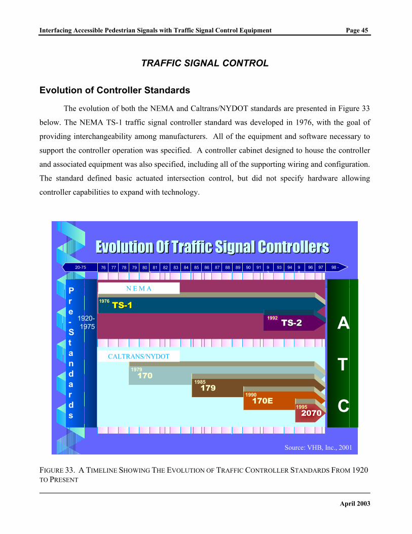
The evolution of both the NEMA and Caltrans/NYDOT standards are presented in Figure 33
below. The NEMA TS-1 traffic signal controller standard was developed in 1976, with the goal of
providing interchangeability among manufacturers. All of the equipment and software necessary to
support the controller operation was specified. A controller cabinet designed to house the controller
and associated equipment was also specified, including all of the supporting wiring and configuration.
The standard defined basic actuated intersection control, but did not specify hardware allowing
controller capabilities to expand with technology.
Evolution Of Traffic Signal ControllersEvolution Of Traffic Signal Controllers
1701979
1791985
170E1990
CALTRANS/NYDOT
TSTS--111976
N E M A
76 77 78 79 80 81 82 83 84 85 86 87 88 89 90 91 92
93 94 95
96 97 98 -20-75
1920-1975
Pre-Standards
A
T
C20701995
TSTS--221992
Source: VHB, Inc., 2001
FIGURE 33. A TIMELINE SHOWING THE EVOLUTION OF TRAFFIC CONTROLLER STANDARDS FROM 1920 TO PRESENT
April 2003
Interfacing Accessible Pedestrian Signals with Traffic Signal Control Equipment Page 46
Advances in technology and the desired functionality of the TS 1 controllers created several
issues. The TS 1 standard focused on the three primary equipment connectors on the front on the
controllers. Manufacturers independently added a fourth connector for preemption, coordination,
additional detector inputs, and system communications that were not interchangeable, preventing
enhanced controller functions. In some cases, system communications was not part of the fourth
connector and was brought in through yet another connector. Additional limitations were identified
with pretimed operations and capabilities beyond basic traffic control.
These limitations led to development of the TS 2 controller standard, developed in 1992. The
TS 2 standard defined two types of controllers and cabinet architectures, the TS 2 Type 1 and TS 2
Type 2. The TS 2 Type 1 controller is unique in the sense that is uses an RS-232/SDLC data link
connection to the peripheral devices, with a separate power connector (5). The TS 2 Type 2 provides
the same connectors as the TS 1 but also includes the data link connector. This allows the TS 2 Type
2 controller to be installed in TS 1 cabinets, reducing the upgrade costs. The TS 2 standard defines
advanced traffic signal operations such as coordination and preemption, and developed standards for
pretimed operations and the cabinet. Advanced cabinet monitoring and diagnostics were defined.
The Type 170 controller standard differed from NEMA standards in that it was a hardware
standard only. Software to run the controller can be supplied by independent vendors and designed to
perform specific applications. Additional standards were developed for ancillary equipment in the
cabinet, and the cabinet itself. The development of the Type 170 controller was an attempt to create a
controller that could be used to meet current and future traffic needs. Rather than require hardware
modification, as with NEMA controllers, the Type 170 responds to new or changing traffic conditions
through upgrades or changes to the software. Nevertheless, some tasks do require hardware
modifications and additions.
The Type 170 specification required that hardware be interchangeable among manufacturers.
Since the software was independent, the controller was basically a general purpose field computer
that could be used for a variety of applications beyond traffic signal control. With the necessary
software, a Type 170 controller could operate in a simple 2-phase operation or control the most
complex interchange. In 1986, the NYS DOT developed the Model 179 controller standard, and in
the early 1990’s, Caltrans developed the Model 170E controller standard. Both were enhancements
to the Model 170 standard to meet current needs, and increased processing power, improved user
display capabilities, provided larger memory storage, and enhanced communications capabilities.
April 2003
Interfacing Accessible Pedestrian Signals with Traffic Signal Control Equipment Page 47
Only a few years later, in 1995, the rapid advances in computer technology led Caltrans to
develop yet another standard, titled the Model 2070. The goal of the 2070 standard was to provide an
advanced controller platform to serve a variety of applications and further define processor, operating
system, and software language, while maintaining general compatibility with previous controller
(Model 170) standards. Expanded processing power in the Model 2070 controller allowed for use in
a wide variety of applications and provided multiple configurations to fit specific system
requirements. The addition of optional VMEBUS modules or serial ports provided additional
functionality to include video-imaging, changeable message sign control, and various other
communication-based functions. The software and hardware interface was standardized, yet the
software remained independent of the controller hardware, allowing for software developed
specifically for the desired application.
Several different configuration profiles were developed with the Type 2070 family, including
the Type 2070N which is compatible with NEMA interfaces and cabinets. Some issues exist today
with the Type 2070 platform, specifically related to the limited number of software vendors and the
high cost of the controller hardware.
Current activities are focused on developing a new controller standard, coined the Advanced
Traffic Controllers (ATC), which combines the best attributes of NEMA, Type 170, Type 2070 along
with emerging ideas and technology. The new ATC platform will provide an open architecture,
allowing for software portability. Open architecture will also provide additional applications, with
the possibility of running multiple applications on one ATC controller. The ATC standard provides
flexibility in hardware development, allowing hardware changes to evolve with technology.
Interchangeability between manufacturers is strongly emphasized including connectors, user
interface, software, communications, internal networks, and computer and modem modules. The
flexibility developed with the ATC standards will allow an ATC controller to work in intersection
control (including APS), real-time surveillance, transit systems, communications hubs, field masters,
ramp metering, sign control, ITE beacons, video systems, environmental systems, and weigh-in-
motion applications.
April 2003
Interfacing Accessible Pedestrian Signals with Traffic Signal Control Equipment Page 48
Typical Controller Cabinet Components NEMA TS 1 and TS 2
Opening the door of a typical NEMA TS 1 controller cabinet will lead you to the controller
itself, along with the conflict monitor, detectors, load switches, other peripheral equipment, and the
necessary internal wiring. A circulating fan and filtered vent are included with each cabinet to
provide air circulation to minimize heat buildup. A light is provided for working in the cabinet
during nighttime hours.
The NEMA TS 2 controller assembly is nearly identical to the TS 1. The two primary
differences are the change in controller unit and the conflict monitor is replaced by a malfunction
management unit (MMU). The MMU is a more advanced device, not only monitoring all of the
conflict voltages, but also communicating with the controller providing an additional element of
monitoring. The TS 2 controller also uses a bus interface unit (BIU) for communication between the
various control components and detectors. The BIU provides a simplification in cabinet wiring while
providing flexibility and power (5). The TS 2 assembly contains a shelf-mounted power supply unit
that provides the appropriate power to each of the controller devices. The detectors in the TS 2
cabinet are rack-mounted. A typical TS 2, Type 1 cabinet is shown in Figure 34.
The controller unit itself simply sits on a shelf in the cabinet. Heavy cables run to each of the
four ports on the front of the controller. The “A” connector provides power to the controller as well
as inputs and outputs to the cabinet (5). The “B” and “C” connectors provide various inputs and
outputs for control. The A, B, and C connectors are standardized by NEMA and are interchangeable
amongst all manufacturers. Each connector is different, preventing cables from being inserted in the
wrong connection port. The “D” connector provides communication, preemption, and expanded
detection capabilities which are used in more advanced systems. Typical controllers have eight
available detection inputs. The D connector provides input for eight additions detectors. The D
connector is used with TS 1 controllers and is not standardized by NEMA, therefore, may not be
interchangeable.
April 2003
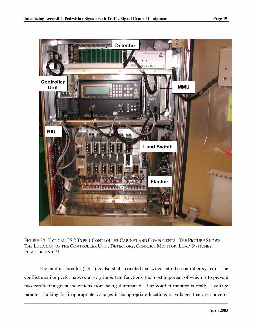
Interfacing Accessible Pedestrian Signals with Traffic Signal Control Equipment Page 49
MMU
FIGURETHE LOFLASHE
conflict
two con
monitor
Controller Unit
U
34. TYPICAL TS 2 TYPE 1 CONTROLLER CABINET AND CATION OF THE CONTROLLER UNIT, DETECTORS, CONFLR, AND BIU.
The conflict monitor (TS 1) is also shelf-mounted and
monitor performs several very important functions, th
flicting green indications from being illuminated. T
, looking for inappropriate voltages in inappropriate
Flasher
Load Switch
Detector
BI
COMPONENTS. THE PICTURE SHOWS ICT MONITOR, LOAD SWITCHES,
wired into the controller system. The
e most important of which is to prevent
he conflict monitor is really a voltage
locations or voltages that are above or
April 2003
Interfacing Accessible Pedestrian Signals with Traffic Signal Control Equipment Page 50
below desired levels. The conflict monitor (5, 6):
• Monitors the cabinet field wiring terminals for voltage on conflicting signal indications, focusing on one or more channels of 120-volt AC inputs (i.e., the green, yellow, red, and WALK);
• Monitors the “absence of red” meaning if the green or yellow is not on, the red should be on (standard feature only in NEMA conflict monitors);
• Monitors cabinet voltage to assure that the proper operating range is maintained;
• Monitors itself for proper supply voltage;
• May monitor intrachannel conflicts and short yellow timing;
• Does not monitor indication voltage to detect light bulbs that may be out unless all green, yellow or WALK bulbs on a channel burn out. Some agencies such as NYDOT require that a current monitoring feature be added to protect against burned out bulbs.
The inductive loop detectors, or loop detector amplifiers, provide a direct connection to the
inductive loops placed in the pavement. Vehicles that pass over the loops are identified by the loop
detector amplifiers through changes in inductance. The detectors send vehicle detection information
to the controller.
The flasher unit provides the flash sequence in the traffic signals. The flash sequence is
implemented either during off-peak hours, most often during late night and early morning times. The
flashers are also used when the conflict monitor overrides the signal system and puts the signals into a
flash mode.
The Bus Interface Unit (BIU) links the Controller to the Cabinet input/output (I/O) elements
(5). It can also be used as a detector interface device. The BIU is responsible for controlling load
switches, providing dimming, receiving and isolating pedestrian calls, analyzing detector faults, time-
stamping detector calls, and providing detector resets. By design, the BIU is free of operator controls.
The BIU performs its I/O functions based upon a pre-wired card rack address.
The load switches receive output from the controller that relay to the terminals located near
the bottom of the cabinet (5). Load switches receive a 12-volt DC input for the green, yellow, and
red indications, and outputs 120 volts AC to the green, yellow and red field terminals.
Controllers satisfying TS 2 standards are categorized by Type 1 and Type 2 features (5). TS 2
Type 1 controllers contain high speed data channels and have increased capabilities, provide
additional diagnostic data, and consume less power than the TS 1 controllers. TS 2 Type 2
controllers contain all of the features of the TS 2 Type 1, but also include additional connectors for
April 2003
Interfacing Accessible Pedestrian Signals with Traffic Signal Control Equipment Page 51
data exchange with the terminals and facilities, and may contain a “D” connector for compatibility
with TS 1 controllers.
Type 170 and Type 2070 The Type 170 and 2070 controller assemblies contain all of the same elements as the NEMA
TS 1 (5). The controller itself, conflict monitor, detectors, load switches, peripheral equipment, and
appropriate wiring are included. The controller assembly has a different look, using a rack-mounted
modular setup. The controller assembly has more of a computer server look than the separate unit
look of a typical NEMA setup. Detectors, power supplies, and preemption devices are modularly
rack-mounted. The card rack for the input and output devices, called the input/output files, are
mounted similarly.
TRAFFIC SIGNAL CONTROLLER MANUFACTURERS Specific information on several traffic signal controllers is presented in the following sections.
Information was obtained through phone, e-mail, and Internet contacts with manufacturers. The
NEMA controllers are presented first, followed by the Type 170/2070 controllers. General
information on conflict monitors and malfunction management units (MMU) is also presented.
Information about traffic signal controllers produced by the following manufacturers is
included in this section:
• Eagle
• Econolite
• McCain
• Naztec
• Peek
• U.S. Traffic
April 2003
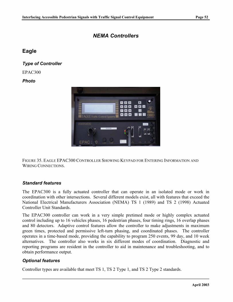
Interfacing Accessible Pedestrian Signals with Traffic Signal Control Equipment Page 52
NEMA Controllers
Eagle
Type of Controller
EPAC300
Photo
FIGURE 35. EAGLE EPAC300 CONTROLLER SHOWING KEYPAD FOR ENTERING INFORMATION AND WIRING CONNECTIONS.
Standard features
The EPAC300 is a fully actuated controller that can operate in an isolated mode or work in coordination with other intersections. Several different models exist, all with features that exceed the National Electrical Manufacturers Association (NEMA) TS 1 (1989) and TS 2 (1998) Actuated Controller Unit Standards.
The EPAC300 controller can work in a very simple pretimed mode or highly complex actuated control including up to 16 vehicles phases, 16 pedestrian phases, four timing rings, 16 overlap phases and 80 detectors. Adaptive control features allow the controller to make adjustments in maximum green times, protected and permissive left-turn phasing, and coordinated phases. The controller operates in a time-based mode, providing the capability to program 250 events, 99 day, and 10 week alternatives. The controller also works in six different modes of coordination. Diagnostic and reporting programs are resident in the controller to aid in maintenance and troubleshooting, and to obtain performance output.
Optional features
Controller types are available that meet TS 1, TS 2 Type 1, and TS 2 Type 2 standards.
April 2003
Interfacing Accessible Pedestrian Signals with Traffic Signal Control Equipment Page 53
Installation notes
EPAC300 controllers require a compatible controller cabinet, conflict monitor/malfunction management unit, and related hardware. Eagle produces a number of cabinets in various sizes.
Manufacturer
Eagle Traffic Control Systems, Austin, TX http://www.eagletcs.com
April 2003
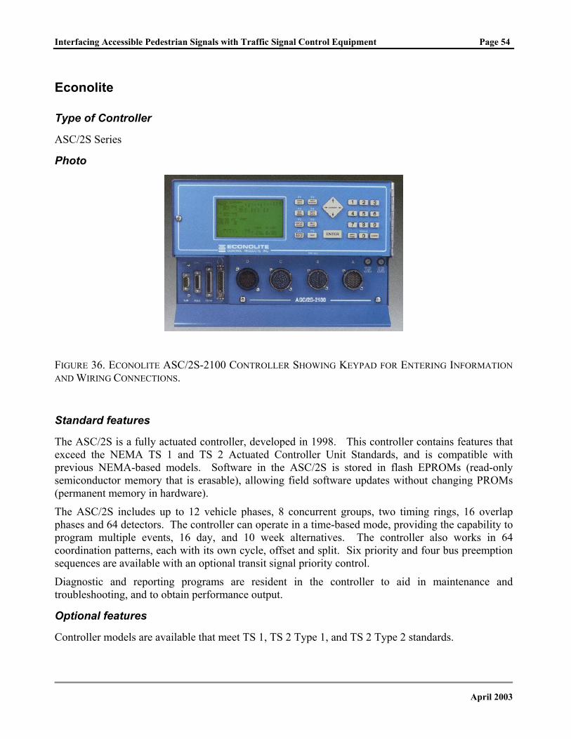
Interfacing Accessible Pedestrian Signals with Traffic Signal Control Equipment Page 54
Econolite
Type of Controller
ASC/2S Series
Photo
FIGURE 36. ECONOLITE ASC/2S-2100 CONTROLLER SHOWING KEYPAD FOR ENTERING INFORMATION AND WIRING CONNECTIONS.
Standard features
The ASC/2S is a fully actuated controller, developed in 1998. This controller contains features that exceed the NEMA TS 1 and TS 2 Actuated Controller Unit Standards, and is compatible with previous NEMA-based models. Software in the ASC/2S is stored in flash EPROMs (read-only semiconductor memory that is erasable), allowing field software updates without changing PROMs (permanent memory in hardware).
The ASC/2S includes up to 12 vehicle phases, 8 concurrent groups, two timing rings, 16 overlap phases and 64 detectors. The controller can operate in a time-based mode, providing the capability to program multiple events, 16 day, and 10 week alternatives. The controller also works in 64 coordination patterns, each with its own cycle, offset and split. Six priority and four bus preemption sequences are available with an optional transit signal priority control.
Diagnostic and reporting programs are resident in the controller to aid in maintenance and troubleshooting, and to obtain performance output.
Optional features
Controller models are available that meet TS 1, TS 2 Type 1, and TS 2 Type 2 standards.
April 2003
Interfacing Accessible Pedestrian Signals with Traffic Signal Control Equipment Page 55
Installation notes
ASC/2S controllers require a compatible controller cabinet, conflict monitor/malfunction management unit, and related hardware. Econolite produces a number of cabinets in various sizes.
Manufacturer
Econolite Control Products, Inc., Anaheim, CA http://www.econolite.com
April 2003
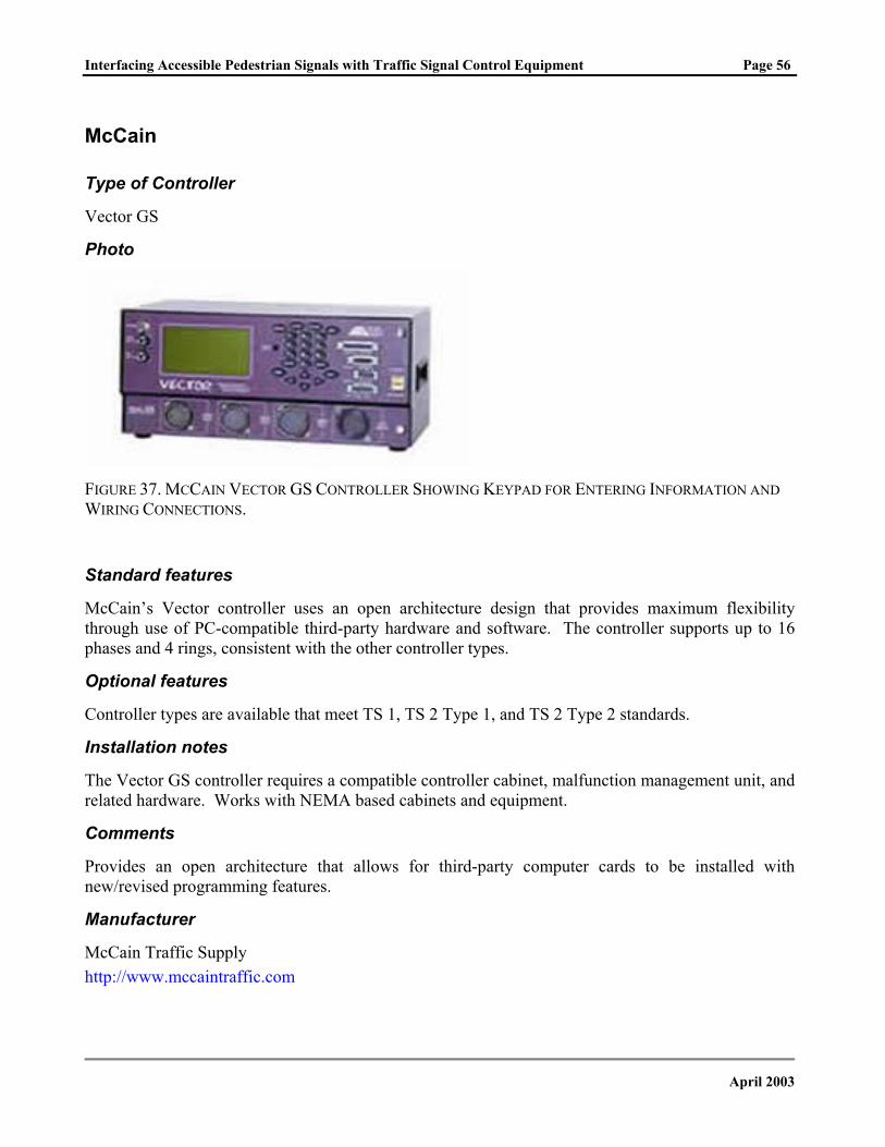
Interfacing Accessible Pedestrian Signals with Traffic Signal Control Equipment Page 56
McCain
Type of Controller
Vector GS
Photo
FIGURE 37. MCCAIN VECTOR GS CONTROLLER SHOWING KEYPAD FOR ENTERING INFORMATION AND WIRING CONNECTIONS.
Standard features
McCain’s Vector controller uses an open architecture design that provides maximum flexibility through use of PC-compatible third-party hardware and software. The controller supports up to 16 phases and 4 rings, consistent with the other controller types.
Optional features
Controller types are available that meet TS 1, TS 2 Type 1, and TS 2 Type 2 standards.
Installation notes
The Vector GS controller requires a compatible controller cabinet, malfunction management unit, and related hardware. Works with NEMA based cabinets and equipment.
Comments
Provides an open architecture that allows for third-party computer cards to be installed with new/revised programming features.
Manufacturer
McCain Traffic Supply http://www.mccaintraffic.com
April 2003
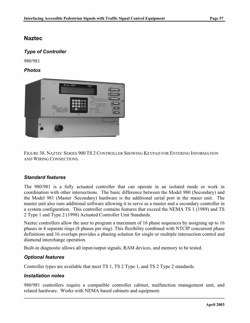
Interfacing Accessible Pedestrian Signals with Traffic Signal Control Equipment Page 57
Naztec
Type of Controller
980/981
Photos
FIGURE 38. NAZTEC SERIES 900 TS 2 CONTROLLER SHOWING KEYPAD FOR ENTERING INFORMATION AND WIRING CONNECTIONS.
Standard features
The 980/981 is a fully actuated controller that can operate in an isolated mode or work in coordination with other intersections. The basic difference between the Model 980 (Secondary) and the Model 981 (Master /Secondary) hardware is the additional serial port in the maser unit. The master unit also runs additional software allowing it to serve as a master and a secondary controller in a system configuration. This controller contains features that exceed the NEMA TS 1 (1989) and TS 2 Type 1 and Type 2 (1998) Actuated Controller Unit Standards.
Naztec controllers allow the user to program a maximum of 16 phase sequences by assigning up to 16 phases in 4 separate rings (8 phases per ring). This flexibility combined with NTCIP concurrent phase definitions and 16 overlaps provides a phasing solution for single or multiple intersection control and diamond interchange operation.
Built-in diagnostic allows all input/output signals, RAM devices, and memory to be tested.
Optional features
Controller types are available that meet TS 1, TS 2 Type 1, and TS 2 Type 2 standards.
Installation notes
980/981 controllers require a compatible controller cabinet, malfunction management unit, and related hardware. Works with NEMA based cabinets and equipment.
April 2003

Interfacing Accessible Pedestrian Signals with Traffic Signal Control Equipment Page 58
Manufacturer
Naztec, Inc., Sugarland, TX 77487 http://www.naztec.com
April 2003
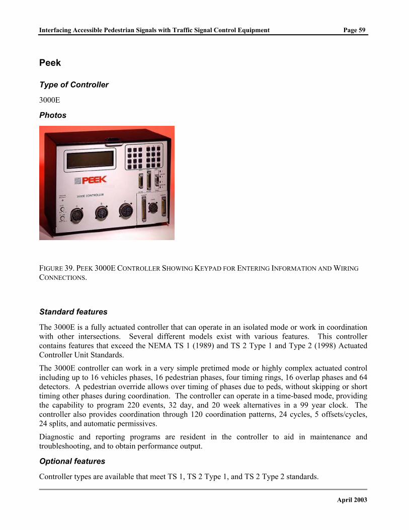
Interfacing Accessible Pedestrian Signals with Traffic Signal Control Equipment Page 59
Peek
Type of Controller
3000E
Photos
FIGURE 39. PEEK 3000E CONTROLLER SHOWING KEYPAD FOR ENTERING INFORMATION AND WIRING CONNECTIONS.
Standard features
The 3000E is a fully actuated controller that can operate in an isolated mode or work in coordination with other intersections. Several different models exist with various features. This controller contains features that exceed the NEMA TS 1 (1989) and TS 2 Type 1 and Type 2 (1998) Actuated Controller Unit Standards.
The 3000E controller can work in a very simple pretimed mode or highly complex actuated control including up to 16 vehicles phases, 16 pedestrian phases, four timing rings, 16 overlap phases and 64 detectors. A pedestrian override allows over timing of phases due to peds, without skipping or short timing other phases during coordination. The controller can operate in a time-based mode, providing the capability to program 220 events, 32 day, and 20 week alternatives in a 99 year clock. The controller also provides coordination through 120 coordination patterns, 24 cycles, 5 offsets/cycles, 24 splits, and automatic permissives.
Diagnostic and reporting programs are resident in the controller to aid in maintenance and troubleshooting, and to obtain performance output.
Optional features
Controller types are available that meet TS 1, TS 2 Type 1, and TS 2 Type 2 standards.
April 2003
Interfacing Accessible Pedestrian Signals with Traffic Signal Control Equipment Page 60
Installation notes
3000E controllers require a compatible controller cabinet, malfunction management unit, and related hardware. Works with NEMA based cabinets and equipment.
Manufacturer
Peek Traffic, Inc., Sarasota, FL 34236 http://www.peekglobal.com
April 2003
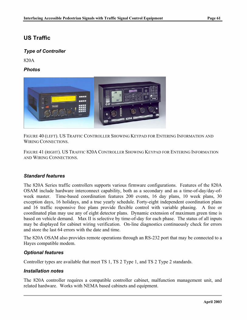
Interfacing Accessible Pedestrian Signals with Traffic Signal Control Equipment Page 61
US Traffic
Type of Controller
820A
Photos
FIGURE 40 (LEFT). US TRAFFIC CONTROLLER SHOWING KEYPAD FOR ENTERING INFORMATION AND WIRING CONNECTIONS.
FIGURE 41 (RIGHT). US TRAFFIC 820A CONTROLLER SHOWING KEYPAD FOR ENTERING INFORMATION AND WIRING CONNECTIONS.
Standard features
The 820A Series traffic controllers supports various firmware configurations. Features of the 820A OSAM include hardware interconnect capability, both as a secondary and as a time-of-day/day-of-week master. Time-based coordination features 200 events, 16 day plans, 10 week plans, 30 exception days, 16 holidays, and a true yearly schedule. Forty-eight independent coordination plans and 16 traffic responsive free plans provide flexible control with variable phasing. A free or coordinated plan may use any of eight detector plans. Dynamic extension of maximum green time is based on vehicle demand. Max II is selective by time-of-day for each phase. The status of all inputs may be displayed for cabinet wiring verification. On-line diagnostics continuously check for errors and store the last 64 errors with the date and time.
The 820A OSAM also provides remote operations through an RS-232 port that may be connected to a Hayes compatible modem.
Optional features
Controller types are available that meet TS 1, TS 2 Type 1, and TS 2 Type 2 standards.
Installation notes
The 820A controller requires a compatible controller cabinet, malfunction management unit, and related hardware. Works with NEMA based cabinets and equipment.
April 2003

Interfacing Accessible Pedestrian Signals with Traffic Signal Control Equipment Page 62
Comments
Provides an open architecture that allows for third-party computer cards to be installed.
Manufacturer
U.S. Traffic Corporation http://www.idc-traffic.com
April 2003
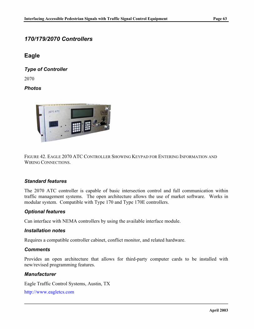
Interfacing Accessible Pedestrian Signals with Traffic Signal Control Equipment Page 63
170/179/2070 Controllers
Eagle
Type of Controller
2070
Photos
FIGURE 42. EAGLE 2070 ATC CONTROLLER SHOWING KEYPAD FOR ENTERING INFORMATION AND WIRING CONNECTIONS.
Standard features
The 2070 ATC controller is capable of basic intersection control and full communication within traffic management systems. The open architecture allows the use of market software. Works in modular system. Compatible with Type 170 and Type 170E controllers.
Optional features
Can interface with NEMA controllers by using the available interface module.
Installation notes
Requires a compatible controller cabinet, conflict monitor, and related hardware.
Comments
Provides an open architecture that allows for third-party computer cards to be installed with new/revised programming features.
Manufacturer
Eagle Traffic Control Systems, Austin, TX
http://www.eagletcs.com
April 2003
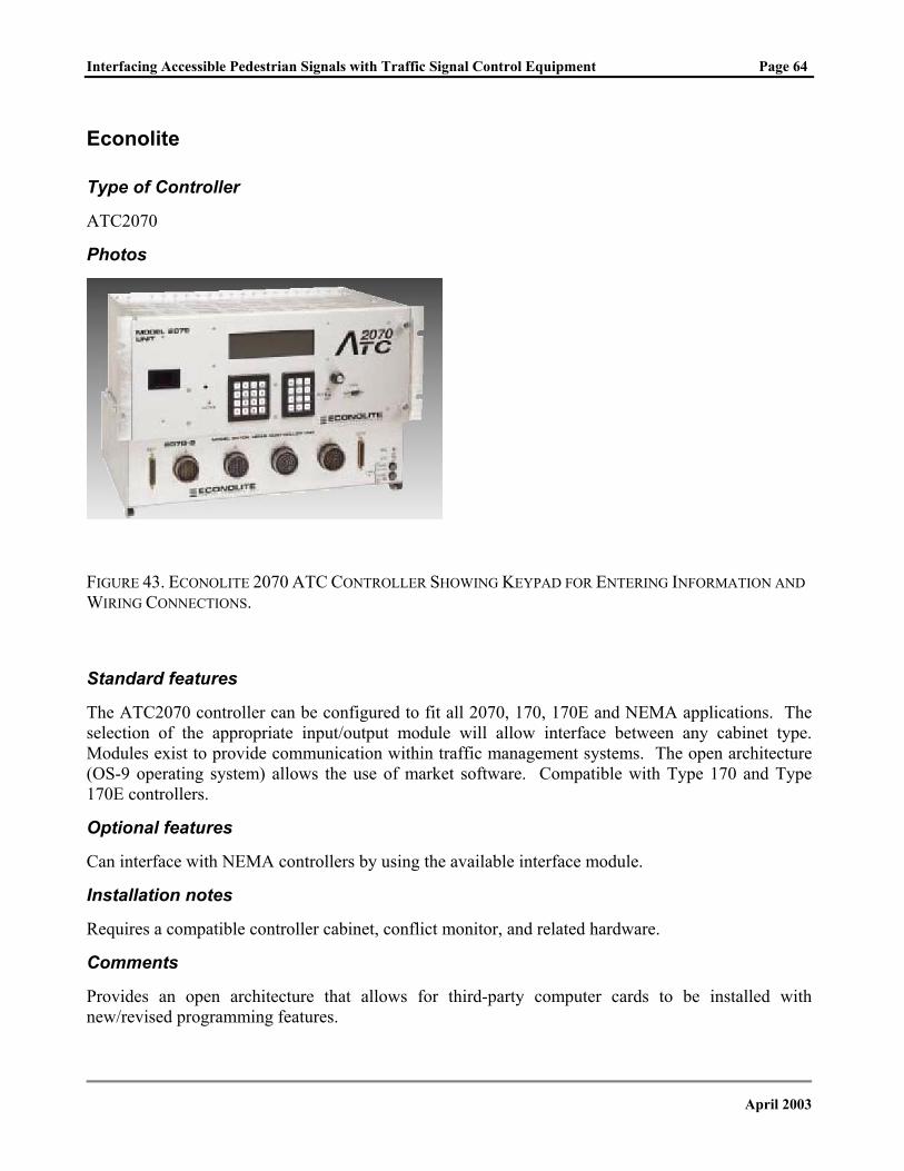
Interfacing Accessible Pedestrian Signals with Traffic Signal Control Equipment Page 64
Econolite
Type of Controller
ATC2070
Photos
FIGURE 43. ECONOLITE 2070 ATC CONTROLLER SHOWING KEYPAD FOR ENTERING INFORMATION AND WIRING CONNECTIONS.
Standard features
The ATC2070 controller can be configured to fit all 2070, 170, 170E and NEMA applications. The selection of the appropriate input/output module will allow interface between any cabinet type. Modules exist to provide communication within traffic management systems. The open architecture (OS-9 operating system) allows the use of market software. Compatible with Type 170 and Type 170E controllers.
Optional features
Can interface with NEMA controllers by using the available interface module.
Installation notes
Requires a compatible controller cabinet, conflict monitor, and related hardware.
Comments
Provides an open architecture that allows for third-party computer cards to be installed with new/revised programming features.
April 2003
Interfacing Accessible Pedestrian Signals with Traffic Signal Control Equipment Page 65
Manufacturer
Econolite Control Products, Inc., Anaheim, CA http://www.econolite.com
April 2003
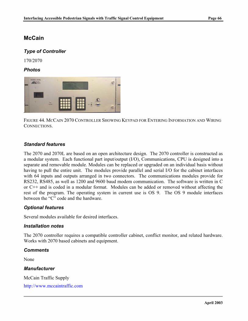
Interfacing Accessible Pedestrian Signals with Traffic Signal Control Equipment Page 66
McCain
Type of Controller
170/2070
Photos
FIGURE 44. MCCAIN 2070 CONTROLLER SHOWING KEYPAD FOR ENTERING INFORMATION AND WIRING CONNECTIONS.
Standard features
The 2070 and 2070L are based on an open architecture design. The 2070 controller is constructed as a modular system. Each functional part input/output (I/O), Communications, CPU is designed into a separate and removable module. Modules can be replaced or upgraded on an individual basis without having to pull the entire unit. The modules provide parallel and serial I/O for the cabinet interfaces with 64 inputs and outputs arranged in two connectors. The communications modules provide for RS232, RS485, as well as 1200 and 9600 baud modem communication. The software is written in C or C++ and is coded in a modular format. Modules can be added or removed without affecting the rest of the program. The operating system in current use is OS 9. The OS 9 module interfaces between the “C” code and the hardware.
Optional features
Several modules available for desired interfaces.
Installation notes
The 2070 controller requires a compatible controller cabinet, conflict monitor, and related hardware. Works with 2070 based cabinets and equipment.
Comments
None
Manufacturer
McCain Traffic Supply
http://www.mccaintraffic.com
April 2003
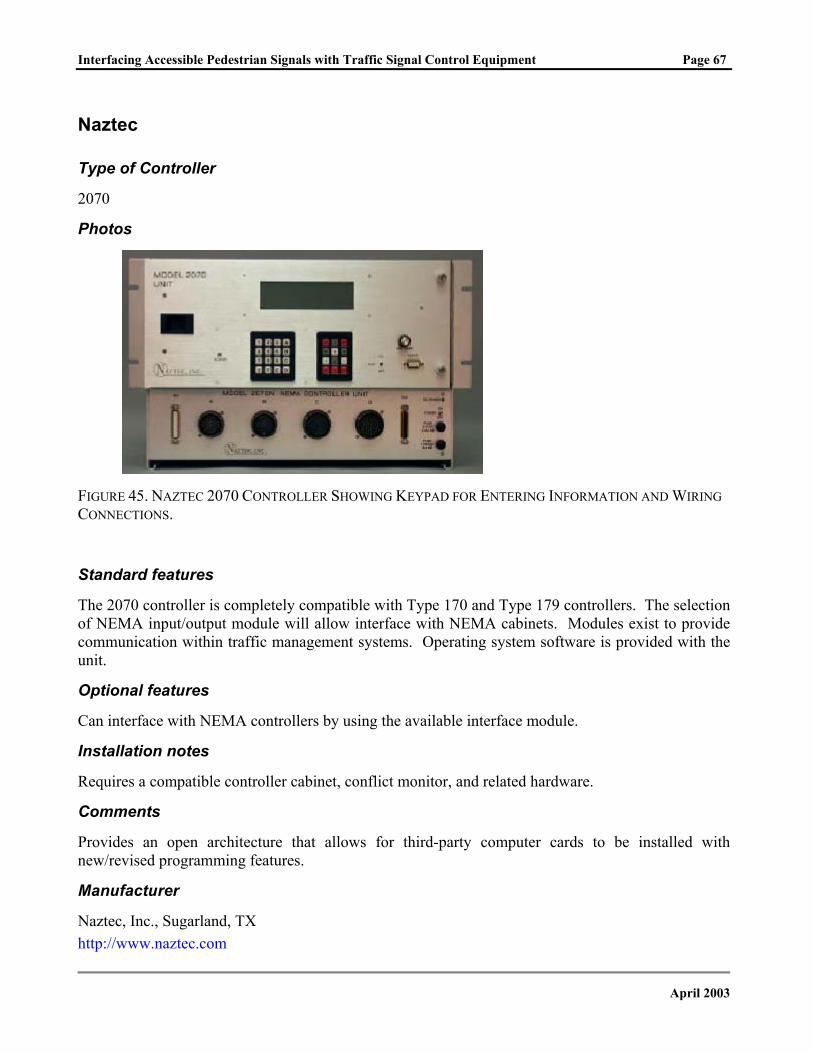
Interfacing Accessible Pedestrian Signals with Traffic Signal Control Equipment Page 67
Naztec
Type of Controller
2070
Photos
FIGURE 45. NAZTEC 2070 CONTROLLER SHOWING KEYPAD FOR ENTERING INFORMATION AND WIRING CONNECTIONS.
Standard features
The 2070 controller is completely compatible with Type 170 and Type 179 controllers. The selection of NEMA input/output module will allow interface with NEMA cabinets. Modules exist to provide communication within traffic management systems. Operating system software is provided with the unit.
Optional features
Can interface with NEMA controllers by using the available interface module.
Installation notes
Requires a compatible controller cabinet, conflict monitor, and related hardware.
Comments
Provides an open architecture that allows for third-party computer cards to be installed with new/revised programming features.
Manufacturer
Naztec, Inc., Sugarland, TX http://www.naztec.com
April 2003
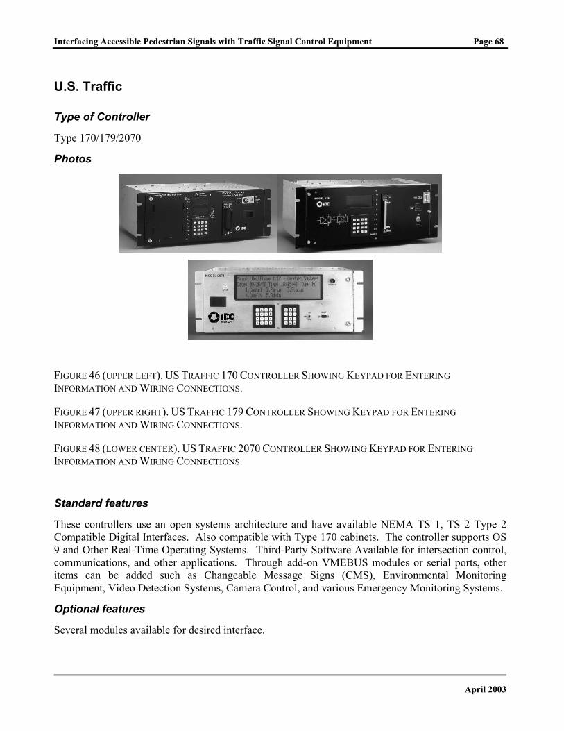
Interfacing Accessible Pedestrian Signals with Traffic Signal Control Equipment Page 68
U.S. Traffic
Type of Controller
Type 170/179/2070
Photos
FIGURE 46 (UPPER LEFT). US TRAFFIC 170 CONTROLLER SHOWING KEYPAD FOR ENTERING INFORMATION AND WIRING CONNECTIONS.
FIGURE 47 (UPPER RIGHT). US TRAFFIC 179 CONTROLLER SHOWING KEYPAD FOR ENTERING INFORMATION AND WIRING CONNECTIONS.
FIGURE 48 (LOWER CENTER). US TRAFFIC 2070 CONTROLLER SHOWING KEYPAD FOR ENTERING INFORMATION AND WIRING CONNECTIONS.
Standard features
These controllers use an open systems architecture and have available NEMA TS 1, TS 2 Type 2 Compatible Digital Interfaces. Also compatible with Type 170 cabinets. The controller supports OS 9 and Other Real-Time Operating Systems. Third-Party Software Available for intersection control, communications, and other applications. Through add-on VMEBUS modules or serial ports, other items can be added such as Changeable Message Signs (CMS), Environmental Monitoring Equipment, Video Detection Systems, Camera Control, and various Emergency Monitoring Systems.
Optional features
Several modules available for desired interface.
April 2003
Interfacing Accessible Pedestrian Signals with Traffic Signal Control Equipment Page 69
Installation notes
The 2070 controller requires a compatible controller cabinet, conflict monitor, and related hardware. Works with 2070 based cabinets and equipment.
Manufacturer
U.S. Traffic Corporation
http://www.idc-traffic.com
April 2003
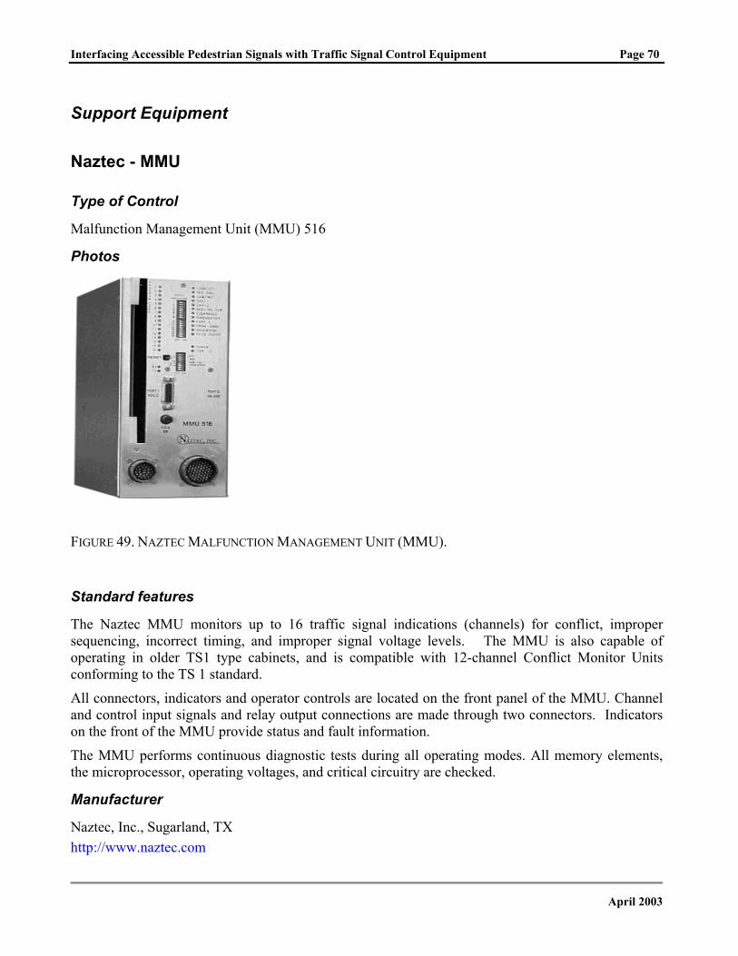
Interfacing Accessible Pedestrian Signals with Traffic Signal Control Equipment Page 70
Support Equipment
Naztec - MMU
Type of Control
Malfunction Management Unit (MMU) 516
Photos
FIGURE 49. NAZTEC MALFUNCTION MANAGEMENT UNIT (MMU).
Standard features
The Naztec MMU monitors up to 16 traffic signal indications (channels) for conflict, improper sequencing, incorrect timing, and improper signal voltage levels. The MMU is also capable of operating in older TS1 type cabinets, and is compatible with 12-channel Conflict Monitor Units conforming to the TS 1 standard.
All connectors, indicators and operator controls are located on the front panel of the MMU. Channel and control input signals and relay output connections are made through two connectors. Indicators on the front of the MMU provide status and fault information.
The MMU performs continuous diagnostic tests during all operating modes. All memory elements, the microprocessor, operating voltages, and critical circuitry are checked.
Manufacturer
Naztec, Inc., Sugarland, TX http://www.naztec.com
April 2003
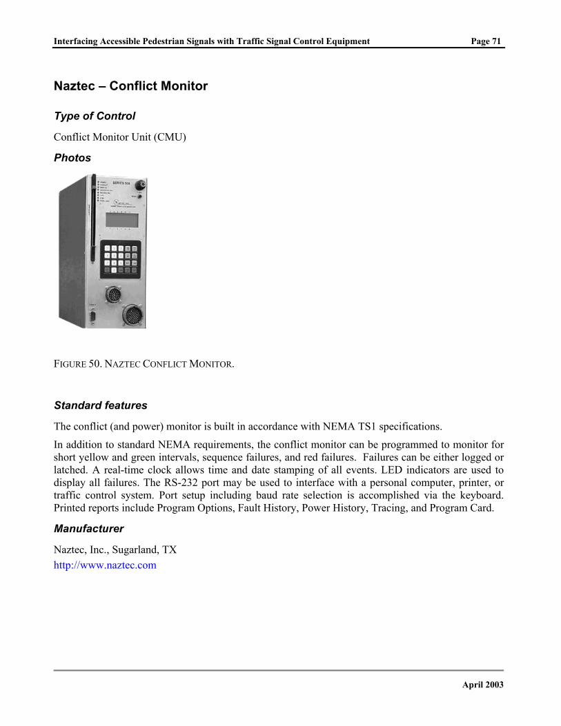
Interfacing Accessible Pedestrian Signals with Traffic Signal Control Equipment Page 71
Naztec – Conflict Monitor
Type of Control
Conflict Monitor Unit (CMU)
Photos
FIGURE 50. NAZTEC CONFLICT MONITOR.
Standard features
The conflict (and power) monitor is built in accordance with NEMA TS1 specifications.
In addition to standard NEMA requirements, the conflict monitor can be programmed to monitor for short yellow and green intervals, sequence failures, and red failures. Failures can be either logged or latched. A real-time clock allows time and date stamping of all events. LED indicators are used to display all failures. The RS-232 port may be used to interface with a personal computer, printer, or traffic control system. Port setup including baud rate selection is accomplished via the keyboard. Printed reports include Program Options, Fault History, Power History, Tracing, and Program Card.
Manufacturer
Naztec, Inc., Sugarland, TX http://www.naztec.com
April 2003
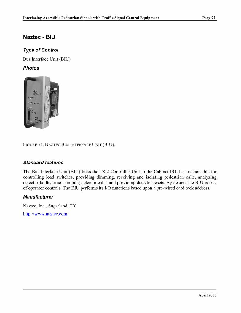
Interfacing Accessible Pedestrian Signals with Traffic Signal Control Equipment Page 72
Naztec - BIU
Type of Control
Bus Interface Unit (BIU)
Photos
FIGURE 51. NAZTEC BUS INTERFACE UNIT (BIU).
Standard features
The Bus Interface Unit (BIU) links the TS-2 Controller Unit to the Cabinet I/O. It is responsible for controlling load switches, providing dimming, receiving and isolating pedestrian calls, analyzing detector faults, time-stamping detector calls, and providing detector resets. By design, the BIU is free of operator controls. The BIU performs its I/O functions based upon a pre-wired card rack address.
Manufacturer
Naztec, Inc., Sugarland, TX
http://www.naztec.com
April 2003
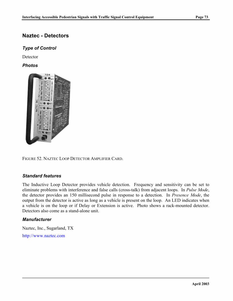
Interfacing Accessible Pedestrian Signals with Traffic Signal Control Equipment Page 73
Naztec - Detectors
Type of Control
Detector
Photos
FIGURE 52. NAZTEC LOOP DETECTOR AMPLIFIER CARD.
Standard features
The Inductive Loop Detector provides vehicle detection. Frequency and sensitivity can be set to eliminate problems with interference and false calls (cross-talk) from adjacent loops. In Pulse Mode, the detector provides an 150 millisecond pulse in response to a detection. In Presence Mode, the output from the detector is active as long as a vehicle is present on the loop. An LED indicates when a vehicle is on the loop or if Delay or Extension is active. Photo shows a rack-mounted detector. Detectors also come as a stand-alone unit.
Manufacturer
Naztec, Inc., Sugarland, TX
http://www.naztec.com
April 2003
Interfacing Accessible Pedestrian Signals with Traffic Signal Control Equipment Page 74
Traffic Signal Controller Manufacturers
The manufacturers listed below offer traffic signal controller and related products. Other manufacturers may exist.
U.S. Traffic Corporation Eagle Traffic Control Systems 9603 John Street 8004 Cameron Road Santa Fe Springs, CA 90670 Austin, TX 78754-3899 Telephone: (562) 923-9600 Telephone: (512) 837-8310 Fax: (562) 923-7555 Fax: (512) 837-0196 E-mail: [email protected] E-mail: [email protected] Web site: http://www.ustraffic.net Web site: http://www.eagletcs.com
Econolite Control Products, Inc. 3360 E. La Palma Anahim, CA 92806-2856 Telephone: (714) 630-3700 Fax: (714) 630-6349 E-mail: [email protected] Web site: http://www.econolite.com Peek Traffic, Inc. 1500 N. Washington Blvd. Sarasota, FL 34236 Telephone: (941) 366-8770 Fax: (941) 365-0837 E-mail: [email protected] Web site: http://www.peekglobal.com Naztec, Inc 820 Park Two Dr. Sugar Land, TX 77478, USA. Telephone: (281) 240-7233 Fax: (281) 240-7238 E-mail: [email protected] Web site: http://www.naztec.com McCain Traffic Supply 2575 Pioneer Avenue Vista, CA 92083 Telephone: (760) 727-8100 Fax: (760) 727-8264 E-mail: [email protected] Web site: http://www.mccaintraffic.com
April 2003
Interfacing Accessible Pedestrian Signals with Traffic Signal Control Equipment Page 75
APPENDIX B - References
REFERENCES
1. Manual on Uniform Traffic Control Devices (MUTCD). Millenium Edition. Federal Highway Administration (FHWA), Washington, D.C., 2000, http://mutcd.fhwa.dot.gov/kno-millenium.htm.
2. Bentzen, B.L. & Tabor, L.S. (1998). Accessible Pedestrian Signals. U.S. Access Board, Washington, D.C., 1998.
3. Building a True Community. Final Report. Public Rights-of-Way Access Advisory Committee (PROWAAC), U.S. Access Board, Washington, D.C., January 2001.
4. History Web Site. http://www.sonic.net/~lindam/historyday/history.html, Accessed October 1, 2002.
5. Pline, James L. (Ed.). Traffic Control Devices Handbook. Institute of Transportation Engineers, Washington, D.C., 2001.
6. Traffic Control System Operations: Installation, Management, and Maintenance. Institute of Transportation Engineers (ITE), Washington, D.C., 2000.
7. Barlow, J.M., Bentzen, B.L., & Tabor, L.S. Accessible Pedestrian Signals: Synthesis and Guide to Best Practice. Draft Report. National Cooperative Highway Research Program, Project 3-62, January 2003.
8. Bentzen, B., Barlow, J., Franck, L. Determining Recommended Language for Speech Messages used by Accessible Pedestrian Signals: Final Report. Accessible Design for the Blind, Berlin, MA, January, 2002.
April 2003