Embed Size (px)
Citation preview

Interference and Diffraction Physics 227 Lab
1
Introduction In the past two labs we've been thinking of light as a particle that reflects off of a surface or refracts into a medium. Now we are going to talk about light as a wave. If you take two waves and add them together, or superimpose them, they will combine together to form a new wave. Below, in Figure 1, you see two different cases in which two waves a can add together. In case 1a, the two waves are in phase, which means that they both reach a peak (or valley) at the same time. When these waves are combined the result will give you constructive interference. In case 1b, the two waves are out of phase in such a way that peaks match with valleys. When these waves are combined the result will give you destructive interference.
If these are waves of light then we could say that constructive interference would give us a brighter light. For light waves that give us destructive interference, we would get darkness.

Interference and Diffraction Physics 227 Lab
2
Double Slit Diffraction
Let’s say that we have a situation in which laser light is incident on two very small slits. The slits are a distance,
d, apart and a screen is placed a distance, L, from the slits. See Figure 2. Light from a laser is monochromatic,
meaning it is made up of light with one wavelength. We use this single wavelength light so that we can simplify
the analysis of the interference effects. If we shine a laser on the slits, the light waves will travel through each
slit and then proceed to the screen. For points on the screen that are off of the central axis, one wave of light
will travel a farther distance than the other.
If the two waves of light are in phase when they meet at the screen then you will see a bright spot (constructive
interference).
If the two beams of light are out of phase when they meet then you will see a dark spot (destructive
interference). As a result, you should see on the screen a pattern of bright and dark spots (or fringes). This
pattern is shown as peaks of brightness and valleys of darkness in Figure 2.
The location of the bright fringes can be found using the following equation.
𝑦 =𝑚𝜆𝐿
𝑑
In the lab you will be measuring the distance, Y, from one bright fringe to its counterpart fringe on the other side of the central axis. See Figure 2. You will then divide this distance by two, y = Y/2, and use this value in the above equation. This process will give you more accurate data.

Interference and Diffraction Physics 227 Lab
3
Single Slit Diffraction
There is also an interference effect when there is only one slit. This is called diffraction. In this situation the light
interferes with itself to produce bright and dark fringes on the screen. The main difference in the pattern is that
the central bright spot for one slit is twice as wide as the central bright spot for two slits. See Figure 3. There are
other differences but they will be left for you to discover during the lab. Also the width of the slit is a.
NOTE: This is not the distance between the slits, like for two slits. For diffraction you will be using the dark fringes as reference points when you are taking data. The equation for the locations of the dark fringes is given below.
𝑦 =𝑚𝜆𝐿
𝑎
Notice that the two equations are pretty much the same except for the d in one denominator and the a in the other. Also, one equation is for locating bright fringes due to interference with two slits. The other is for dark fringes due to diffraction with a single slit. You will be using these two equations to calculate the wavelength of the light from the laser. You will then compare this value to the known value of the wavelength.

Interference and Diffraction Physics 227 Lab
4
The Equipment You will be using the same optical bench set-up that you used last week. See Figure 4. In this lab however you will be using a laser as the light source. Do not shine the laser into your lab partner's eyes! There should be paper on your table for you to attach to the screen with a black clip. Do not write on the screen!
Table 1: Data table
Single Slit L = a =
m Y y
1
2
...
6
Average λave:
% Error: What you need to do: Part 1 - Single Slit Place the Single Slit Disc on the optical bench. It should be about 3 or 4 cm from the laser. Rotate the disc so that the 0.08mm (use 0.088mm for calculations) slit is in the path of the laser beam. The screen should be at 110cm. Using the black clip on the screen, attach the piece of paper to the screen. Adjust the laser to the left or the right so as to get as bright and sharp a pattern as possible on the screen. Make a copy of Table 1 in your lab report. "m" should range from 1 to 6. Now do the following ...

Interference and Diffraction Physics 227 Lab
5
A.) Write on the piece of paper, "Single Slit, a = 0.088mm". Also place the value in your table.
B.) Measure the distance, L, from the SLIT to the screen.(Not from the laser)
NOTE: The disc is not even with marker at the base of the mount.
C.) Using the 1st through the 6th order dark fringes, make marks at the estimated centers of the dark fringes.
D.) Label on the paper the order number for each pair of fringes.
E.) Remove the paper and put up a new piece of paper. DO NOT USE THE SAME SHEET! You'll use this for the double slit.
Using your marked pattern, do the following for each fringe pair ...
F.) Measure the distance, Y, from one dark fringe to the other for the same order number. See Figure 3.
Place these values in the table.
G.) Calculate the distance, y, which is the distance from the center of the central maximum to a dark fringe. Place these values in the table.
H.) Using the Single Slit - Dark Fringe equation, calculate the wavelength for each order. (Make sure all of
the values are in meters before you substitute in the numbers.) Place these values in the table.
I.) Find the average of your 6 wavelengths.
J.) Calculate a percent error based on the known wavelength for the green laser light, 532nm, or red laser light, 650 nm.
Question #1 Turn the disc to the Variable Slit section. Rotate the disc while the laser is centered on the variable slit. Describe what happens to the pattern as the slit width increases. Does this agree with the y = m L=a equation? Explain.
Question #2 Turn the disc so that the laser is shining on one of the following three patterns: squares, hexes, holes.
a. For each pattern, describe or diagram what you are seeing. b. Based on what you have seen in the first part of the lab, explain why the patterns look the way they do
for each type of "slit".
Interference and Diffraction Physics 227 Lab
6
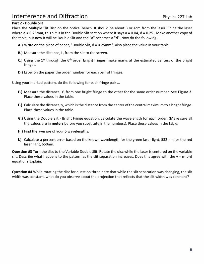
Part 2 - Double Slit Place the Multiple Slit Disc on the optical bench. It should be about 3 or 4cm from the laser. Shine the laser where d = 0.25mm, this slit is in the Double Slit section where it says a = 0.04, d = 0.25.. Make another copy of the table, but now it will be Double Slit and the "a" becomes a "d". Now do the following ...
A.) Write on the piece of paper, "Double Slit, d = 0.25mm". Also place the value in your table.
B.) Measure the distance, L, from the slit to the screen.
C.) Using the 1st through the 6th order bright fringes, make marks at the estimated centers of the bright fringes.
D.) Label on the paper the order number for each pair of fringes.
Using your marked pattern, do the following for each fringe pair ...
E.) Measure the distance, Y, from one bright fringe to the other for the same order number. See Figure 2.
Place these values in the table.
F.) Calculate the distance, y, which is the distance from the center of the central maximum to a bright fringe. Place these values in the table.
G.) Using the Double Slit - Bright Fringe equation, calculate the wavelength for each order. (Make sure all
the values are in meters before you substitute in the numbers). Place these values in the table.
H.) Find the average of your 6 wavelengths.
I.) Calculate a percent error based on the known wavelength for the green laser light, 532 nm, or the red laser light, 650nm.
Question #3 Turn the disc to the Variable Double Slit. Rotate the disc while the laser is centered on the variable slit. Describe what happens to the pattern as the slit separation increases. Does this agree with the y = m L=d equation? Explain.
Question #4 While rotating the disc for question three note that while the slit separation was changing, the slit width was constant, what do you observe about the projection that reflects that the slit width was constant?

Interference and Diffraction Physics 227 Lab
7
CD and DVDs For this part of the experiment we will use the grooves
on a cd for multiple slit interference. As shown on the
right the actual slits we are working with are the lines of
indents. For standard cases one side of the CD or DVD
has a reflective material, but if we remove the reflective
material we can use the clear disk for multiple slit
transmission. Keep in mind the area the laser will be
shining on is much much larger than that pictured here,
approximately 1000 times so.
The setup you will use is shown below. Be sure to note the location of the laser is such so that it is hitting the groove where it is approximately vertical. You’ll also find pictures of the setup on the following page.

Interference and Diffraction Physics 227 Lab
8
Figure 1: Picture of CD setup
Figure 2: Picture of CD setup

Interference and Diffraction Physics 227 Lab
9
Calculations: Now calculate θ and d (The groove spacing) using values you can measure here. As with the double slit experiment measure the distance between bright fringes to find y. Then measure L and you should be able to find θ from these two. Hint: Use either sin θ or tan θ .
Next use the formula for diffraction, (remember this one, we’ll be using it quite often this semester)
𝑑𝑠𝑖𝑛 𝜃 = 𝑚𝜆
to find the groove spacing d. For your calculation here use the given lambda for the green or red laser light of 532nm, or 650nm. Now repeat this using either a transparent or reflective DVD. Calculate θ and d again for a DVD. Question 5: How do the CD and DVD compare? Does this correspond with what you know about the amount of information on each respective disk?
Question 6: To get a feel for the size of these grooves compare this distance d to the size of the average human red blood cell of 10 μm. Are they smaller, larger, about the same? Question 7: Can you observe second and third order diffraction for CD? (this is when m=2 or 3 in figure 3) How about for the DVD? Try to explain why or why not. Appendix:
Interference and Diffraction Physics 227 Lab
10
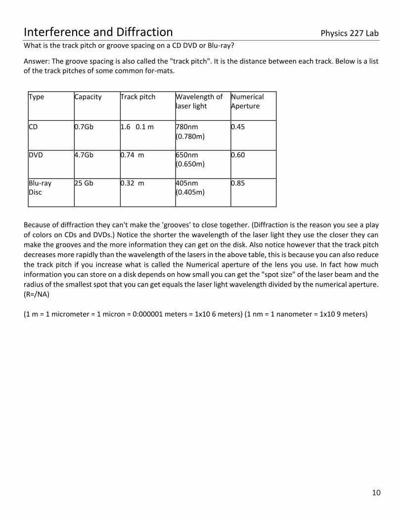
What is the track pitch or groove spacing on a CD DVD or Blu-ray? Answer: The groove spacing is also called the "track pitch". It is the distance between each track. Below is a list of the track pitches of some common for-mats.
Type Capacity Track pitch Wavelength of Numerical laser light Aperture
CD 0.7Gb 1.6 0.1 m 780nm 0.45 (0.780m) DVD 4.7Gb 0.74 m 650nm 0.60 (0.650m) Blu-ray 25 Gb 0.32 m 405nm 0.85 Disc (0.405m)
Because of diffraction they can't make the 'grooves' to close together. (Diffraction is the reason you see a play
of colors on CDs and DVDs.) Notice the shorter the wavelength of the laser light they use the closer they can
make the grooves and the more information they can get on the disk. Also notice however that the track pitch
decreases more rapidly than the wavelength of the lasers in the above table, this is because you can also reduce
the track pitch if you increase what is called the Numerical aperture of the lens you use. In fact how much information you can store on a disk depends on how small you can get the "spot size" of the laser beam and the
radius of the smallest spot that you can get equals the laser light wavelength divided by the numerical aperture. (R=/NA)
(1 m = 1 micrometer = 1 micron = 0:000001 meters = 1x10 6 meters) (1 nm = 1 nanometer = 1x10 9 meters)