Embed Size (px)
Citation preview
Hindawi Publishing CorporationInternational Journal of Digital Multimedia BroadcastingVolume 2010, Article ID 689705, 11 pagesdoi:10.1155/2010/689705
Research Article
Interference Coordination for E-MBMS Transmissions inLTE-Advanced
Alberto A. Lopes,1 Jose Seguro,1 Paulo Gomes,1 Nuno Souto,1, 2 and Americo Correia1, 2
1 Instituto de Telecomunicacoes, Av. Rovisco Pais, 1049-001 Lisboa, Portugal2 ISCTE-IUL, Av. Das forces Armadas, 1649-026 Lisboa, Portugal
Correspondence should be addressed to Americo Correia, [email protected]
Received 1 April 2010; Accepted 18 August 2010
Academic Editor: Ivan Bajic
Copyright © 2010 Alberto A. Lopes et al. This is an open access article distributed under the Creative Commons AttributionLicense, which permits unrestricted use, distribution, and reproduction in any medium, provided the original work is properlycited.
Interference coordination methods for Evolved-Multimedia Broadcast/Multicast Service (E-MBMS) in Long-Term EvolutionAdvanced (LTE-A) are presented. In addition, we consider signal space diversity based on Rotation Matrices (RM) known toprovide good performance gains over uncorrelated Rayleigh fading channels. OFDM/OFDMA systems can make the use of RMvery attractive both for single and multiple antenna transmissions. In this paper, OFDM/OFDMA signals based on LTE parametersare combined with RM, MIMO, Turbo, or LDPC codes. We have considered different types of receivers, namely, we used an MMSE(Minimum Mean Squared Error) equalizer and a Maximum Likelihood Soft Output criterion (MLSO). Frequency, signal, andspace diversity gains are evaluated for different spatial channel models (SCM) based on ITU multipath propagation channels.Different adaptive frequency reuse and schedulers are considered to evaluate the E-MBMS spectral efficiency at the cell borders.
1. Introduction
Long-Term Evolution Advanced (LTE-A) considers a seriesof new transmission technologies, such as, coordinatedmultipoint transmission and reception, relay and carrieraggregation. The objective is to meet the high technicaland services requirements of IMT-Advanced standards, suchas, peak data rate up to 100 Mbps in high-speed mobilityenvironment and 1 Gbps in a pedestrian environment. Thebandwidth varies from 20 MHz to 100 MHz. The LTEstandard is the basic standard that paves the way for thefuture 4th Generation (4G) wireless networks.
LTE addresses the emerging trend for the mass provisionof rich multimedia services, such as Mobile TV, in a morepowerful and spectral efficient way than its predecessors. TheEvolved-Multimedia Broadcast/Multicast Service (E-MBMS)framework is envisaged to play an essential role for the LTE-Aproliferation in mobile environments. E-MBMS constitutesthe evolutionary successor of MBMS, which was introducedin the Release 6 of Universal Mobile TelecommunicationSystem (UMTS). With E-MBMS, the mass provision ofmultimedia applications to mobile users will be a reality.
With the introduction of Multimedia Broadcast and Mul-ticast Service (MBMS) [1], cellular broadcast will becomean essential delivery option of Mobile TV. TV channels canthen be broadcasted to an unlimited number of users. Onthe other hand, the number of channels is limited due tothe available broadcast capacity. As MBMS indicates, thereare two types of service mode: the broadcast mode andthe multicast mode. Each mode has different characteristicsin terms of complexity and packet delivery. The broadcastservice mode is a unidirectional transmission type. In thisservice mode, content is delivered, using point-to-multipoint(PTM) transmission, to a specified area without knowing thereceivers and whether there is any receiver in the area. Inthe multicast mode, data is transmitted solely to users thatexplicitly request such a service. So, there is the possibilityfor the network to selectively transmit to cells, which containmembers of a multicast group. Either point-to-point (PTP)or PTM transmission can be configured in each cell for themulticast operation mode.
PTM transmission does not employ feedback and there-fore needs to be statically configured to provide desiredcoverage in the cell. The transmitted signal is lowest at the cell
2 International Journal of Digital Multimedia Broadcasting
Figure 1: Cooperative MIMO system.
border and therefore the PTM bearer can greatly benefit fromexploiting also the signals from adjacent cells transmittingthe same service, that is, from soft-combining.
Two types of Evolved-MBMS transmission scenariosexist:
(1) multi-cell transmission (MBSFN: Multi-MediaBroadcast over a Single Frequency Network) on adedicated frequency layer or on a shared frequencylayer,
(2) single-cell transmission (SCPTM: Single Cell Point toMultipoint) on a shared frequency layer.
Intercell interference coordination is one method hereconsidered which is expected to improve coverage andincrease cell-edge bitrate [2]. Intercell interference co-ordination techniques, such as reuse schemes and channelallocation, have been studied thoroughly for circuit switchedservices in second generation accesses [3].
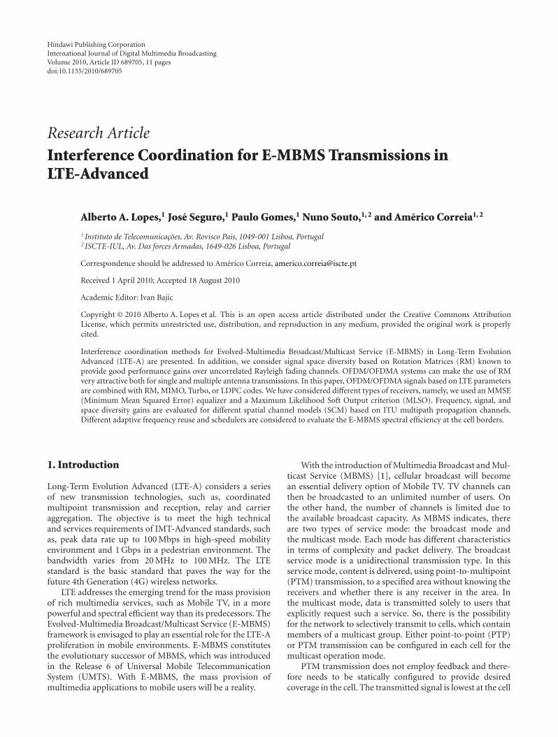
Cooperative MIMO is another emerging technique tocombat intercell interference and improve cell edge perfor-mance [4]. The system architecture is illustrated in Figure 1.
Sharing data and channel state information amongneighboring base stations (BSs) allows to coordinate theirtransmissions in the downlink and jointly process thereceived signals in the uplink. Cooperative MIMO tech-niques can effectively turn intercell interference into usefulsignals, allowing significant power and diversity gains tobe exploited. The architecture of the high-speed backboneenables the exchange of information (data and controlinformation) between the BSs. Cooperative MIMO systemsare only concerned with the BS to mobile station (MS)channel which are PTM channels.
The receiver performance of E-MBMS is expected tobe improved compared to earlier accesses. OrthogonalFrequency Division Multiple Access (OFDMA) significantlyreduces intracell interference compared to MBMS basedon CDMA technology. Two receiver antennas are expectedto be mandatory in the User Equipment (UE) to mitigateintercell interference. We consider Orthogonal Frequency-Division Multiplexing/ Orthogonal Frequency Division Mul-tiple Access (OFDM/OFDMA) where the use of Turbo orLDPC codes in combination with multiple input multipleoutput (MIMO) and signal space diversity is exploited toachieve several gains in band-limited wireless communica-tion systems.
In this paper, we present Turbo and LDPC codes coupledwith signal space diversity provided by Rotation Matrices(RM) both Real RM and Complex RM. Both QPSK andM-QAM modulation schemes in several ITU propagationchannels will be evaluated starting with a block uncorrelatedRayleigh fading channel. To maximize the diversity order,the constellation of the MQAM signal should be properlyrotated such that all distinct symbols are separable on everycoordinate.
Two different iterative receivers are introduced to exploitthe frequency, signal space, and spatial diversities of OFDMsignals with Turbo and LDPC codes, MIMO and RM.
Section 2 introduces the system model and outlines themain blocks of the transmitter and receivers including thesignal space diversity provided by RM. The coordinatedMIMO and interference schemes are presented in Section 3.Performance curves at link and system level are presented inSection 4, followed by conclusions in Section 5.
2. System Model
Powerful forward error correction (FEC) codes like Turboand LDPC codes can achieve excellent performances overadditive white Gaussian noise (AWGN) channels [5, 6].To explore their potential as capacity achieving codes formore realistic wireless channels, we combine them withthe use of complex rotation matrices (CRM) [7] and realrotation matrices (RRM) specific to obtain multiresolutionwith MIMO. RMs provide signal space diversity which canimprove the robustness against fading.
Fading causes significant performance degradation inwireless digital communication systems. An optimum designfor an AWGN channel does not necessarily result in the bestperformance in fading channels. Therefore, maximizing theminimum squared Euclidean distance does not necessarilyminimize the error probability of this type of channels [8].Coded modulation techniques coupled with interleaving canimprove the performance for block fading channels. It wasshown in [9], that for a block fading wireless communicationlink, diversity can be introduced into the system by separatelyinterleaving the in-phase and quadrature components of aM-QAM scheme and performing symbol-by-symbol detec-tion. It was shown that there was a dependency between theperformance of the system and the rotation angle employedin fading channels whereas it was not affected in an AWGNchannel.
International Journal of Digital Multimedia Broadcasting 3
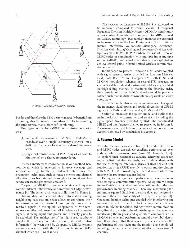
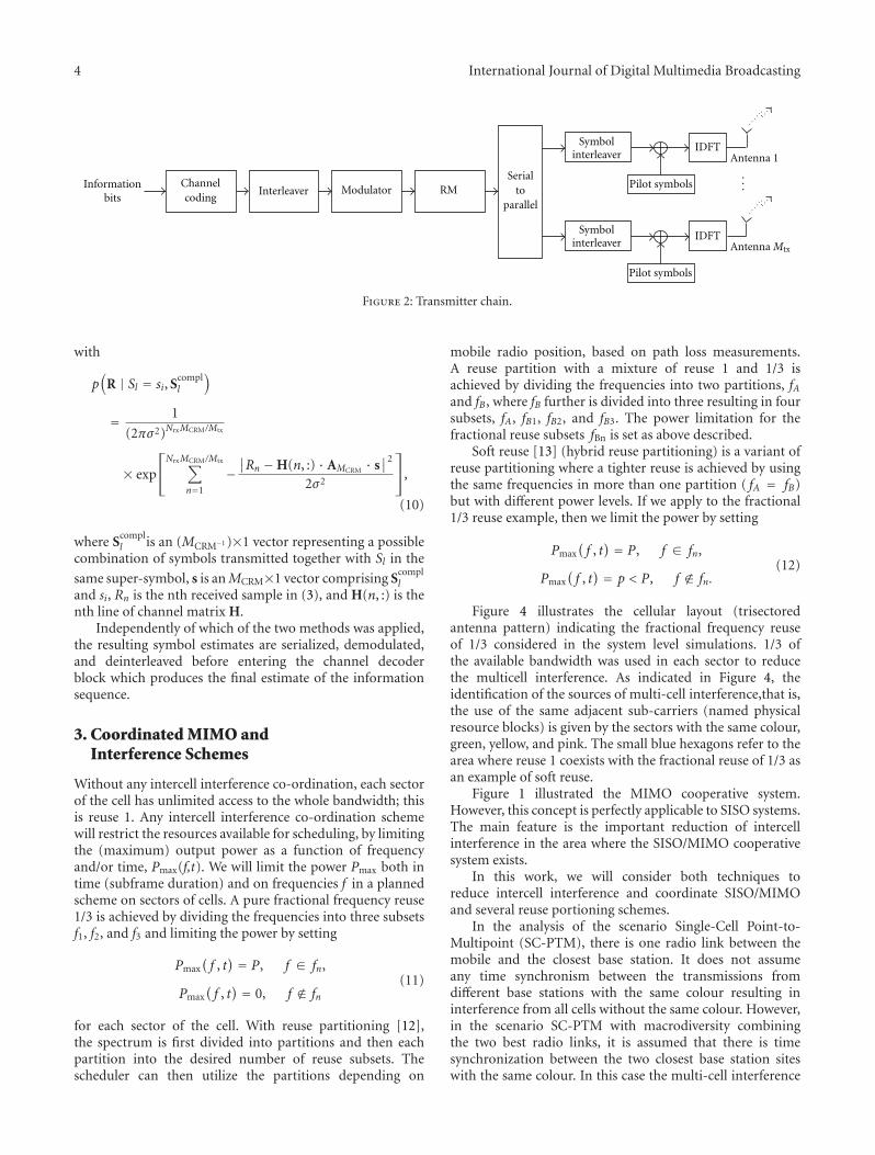
2.1. Transmitter. Figure 2 shows the block diagram of anOFDM-MIMO transmitter with RM incorporated. Accord-ing to the scheme an information block is firstly encoded,interleaved, and mapped onto the constellation symbols.RM is applied to the resulting sequence by grouping thesymbols into size-MCRM super-symbols and multiplyingthem by rotation matrix AMCRM . When CRM is employed,matrix AMCRM belongs to the family of orthonormal complexmatrices which, for MCRM= 2n(n ≥ 2), are defined as [7]
AMCRM=
⎧⎪⎪⎪⎪⎪⎪⎪⎪⎨
⎪⎪⎪⎪⎪⎪⎪⎪⎩
⎡
⎣e jφ je− jφ
− je jφ e− jφ
⎤
⎦/|A2|1/2, MCRM=2,
⎡
⎣AMCRM/2 AMCRM/2
AMCRM/2 −AMCRM/2
⎤
⎦/∣∣AMCRM
∣∣1/MCRM , MCRM>2,
(1)
with |A2| = det(A2), |AMCRM| = det(AMCRM ), and ϕ beingthe rotation angle.
A rotated super-symbol can be represented as the vectorobtained from
X = AMCRM · S, (2)
where S is an MCRM×1 vector with a set of modulatedsymbols composing a super-symbol. The resulting sequenceis split into Mtx parallel streams which are interleaved in thesymbol interleaver. The objective of the symbol interleaveris to explore the characteristics of OFDM transmissionsin severe time-dispersive environments whose channel fre-quency response can change significantly between differentsubcarriers. Although the different samples are split betweenthe different transmitting antennas, the interleaver insuresthat samples of a super-symbol transmitted in the sameantenna are mapped to distant subcarriers and thus cantake advantage of the diversity in the frequency domain.Therefore, the number of transmitting antennas can be lowerthan the size of the super-symbols, that is, MCRM ≥ Mtx.An IDFT (Inverse Discrete Fourier Transform) is applied tothe individual sequences, which converts them to the timedomain before being transmitted by the respective antennas.
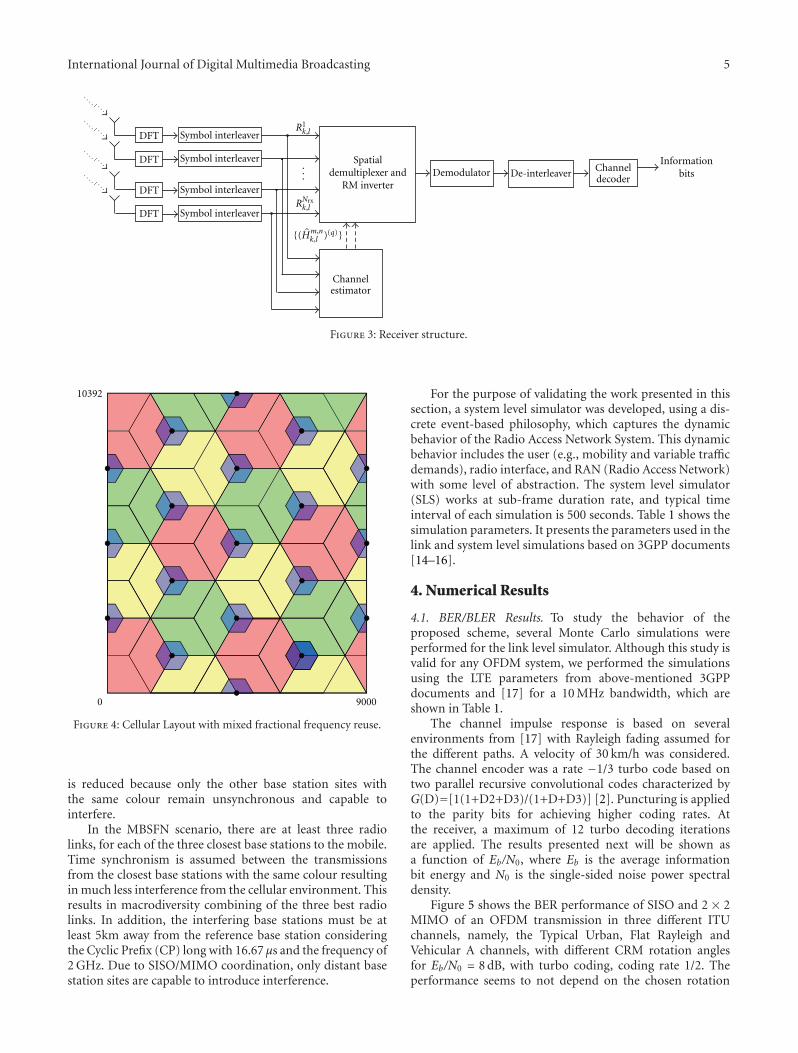
2.2. Receiver. Figure 3 presents the scheme of the receiveremployed assuming the use of Nrx receiving antennas.According to the figure, the signal, which is considered to besampled and with the cyclic prefix removed, is converted tothe frequency domain through an appropriate size-N DFToperation and the sequence of symbols is deinterleaved.Assuming that the cyclic prefix is longer than the overallchannel impulse response, each received MCRM-sized super-symbol can be represented using matrix notation as
R = H ·X + N, (3)
where H is the frequency response channel matrix. Matrix His defined as a blockwise diagonal matrix according to
H =
⎡
⎢⎢⎣
H1 0. . .
0 HMCRM/Mtx
⎤
⎥⎥⎦ (4)
with
Hk =
⎡
⎢⎢⎣
H1,1k · · · H1,Mtx
k...
. . ....
HNrx,1k · · · HNrx,Mtx
k
⎤
⎥⎥⎦, k = 1, ...,MCRM/Mtx.
(5)
Index k represents a subcarrier position. It is importantto note that due to the presence of the symbol interleaverthe different sub-carriers denoted by index k may not benecessarily adjacent. To simplify we will assume that MCRM
is a multiple of the number of transmitting antennas Mtx·Nis a (Nrx·MCRM / Mtx) × 1 vector containing additive whiteGaussian noise (AWGN) samples.
The super-symbol’s samples enter the Spatial Demulti-plexer and CRM Inverter block which separates the streamstransmitted simultaneously by the multiple antennas andinverts the rotation applied at the transmitter. Two alter-native methods are employed in this paper: an MMSE(Minimum Mean Squared Error) equalizer [10] and aMaximum Likelihood-based Soft Output (MLSO) detector.
Regarding the first approach, MMSE criterion is appliedto each individual subcarrier using [10, 11]
Xk = (Hk)H ·[
Hk(Hk)H + σ2I]−1
Rk, (6)
where Xk is the Mtx × 1 vector with the estimated subset ofcoordinates from the super-symbol mapped to sub-carrier k,Rk is the Nrx×1 received signal vector in sub-carrier k withone different receive antenna in each position, and σ 2 is thenoise variance. Using the rotated super-symbol estimates Xk,the component symbol estimates are computed through
S = (AMCRM
)−1 · X. (7)
In the MLSO criterion, the following estimate is computedfor each symbol
Sl = E[Sl | R]
=∑
si∈Λsi · P(Sl = si | R)
=∑
si∈Λsi · P(Sl = si)
p(R)p(R | Sl = si),
(8)
with si representing a constellation symbol from the mod-ulation alphabet Λ, E[·] denoting the expected value,P(·) a discrete probability, and p(·) a probability densityfunction (PDF). Considering equiprobable symbols, we haveP(Sl = si) = 1/M, where M is the constellation size. The PDFvalues required in (8) can be computed as
p(R | Sl = si) = 1MMCRM−1
∑
Scompll ∈ΛMCRM−1
p(
R | Sl = si, Scompll
)
(9)
4 International Journal of Digital Multimedia Broadcasting
Serialto
parallel
...
Antenna 1IDFT
IDFT
Pilot symbols
Pilot symbols
Channelcoding
ModulatorInterleaver RM
Symbolinterleaver
Symbolinterleaver
Informationbits
Antenna Mtx
Figure 2: Transmitter chain.
with
p(
R | Sl = si, Scompll
)
= 1
(2πσ2)NrxMCRM/Mtx
× exp
⎡
⎣
NrxMCRM/Mtx∑
n=1
−∣∣Rn −H(n, :) · AMCRM · s
∣∣2
2σ2
⎤
⎦,
(10)
where Scompll is an (MCRM−1 )×1 vector representing a possible
combination of symbols transmitted together with Sl in the
same super-symbol, s is an MCRM×1 vector comprising Scompll
and si, Rn is the nth received sample in (3), and H(n, :) is thenth line of channel matrix H.
Independently of which of the two methods was applied,the resulting symbol estimates are serialized, demodulated,and deinterleaved before entering the channel decoderblock which produces the final estimate of the informationsequence.
3. Coordinated MIMO andInterference Schemes
Without any intercell interference co-ordination, each sectorof the cell has unlimited access to the whole bandwidth; thisis reuse 1. Any intercell interference co-ordination schemewill restrict the resources available for scheduling, by limitingthe (maximum) output power as a function of frequencyand/or time, Pmax(f,t). We will limit the power Pmax both intime (subframe duration) and on frequencies f in a plannedscheme on sectors of cells. A pure fractional frequency reuse1/3 is achieved by dividing the frequencies into three subsetsf1, f2, and f3 and limiting the power by setting
Pmax(f , t) = P, f ∈ fn,
Pmax(f , t) = 0, f /∈ fn
(11)
for each sector of the cell. With reuse partitioning [12],the spectrum is first divided into partitions and then eachpartition into the desired number of reuse subsets. Thescheduler can then utilize the partitions depending on
mobile radio position, based on path loss measurements.A reuse partition with a mixture of reuse 1 and 1/3 isachieved by dividing the frequencies into two partitions, fAand fB, where fB further is divided into three resulting in foursubsets, fA, fB1, fB2, and fB3. The power limitation for thefractional reuse subsets fBn is set as above described.
Soft reuse [13] (hybrid reuse partitioning) is a variant ofreuse partitioning where a tighter reuse is achieved by usingthe same frequencies in more than one partition ( fA = fB)but with different power levels. If we apply to the fractional1/3 reuse example, then we limit the power by setting
Pmax(f , t) = P, f ∈ fn,
Pmax(f , t) = p < P, f /∈ fn.
(12)
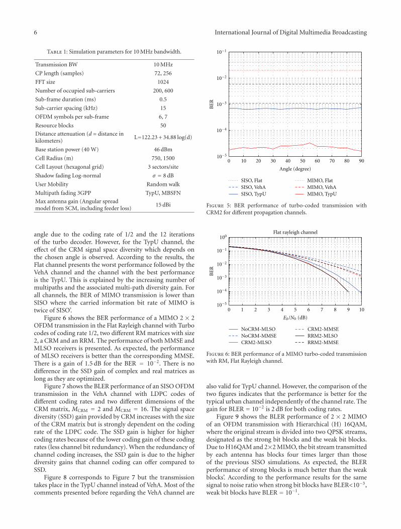
Figure 4 illustrates the cellular layout (trisectoredantenna pattern) indicating the fractional frequency reuseof 1/3 considered in the system level simulations. 1/3 ofthe available bandwidth was used in each sector to reducethe multicell interference. As indicated in Figure 4, theidentification of the sources of multi-cell interference,that is,the use of the same adjacent sub-carriers (named physicalresource blocks) is given by the sectors with the same colour,green, yellow, and pink. The small blue hexagons refer to thearea where reuse 1 coexists with the fractional reuse of 1/3 asan example of soft reuse.
Figure 1 illustrated the MIMO cooperative system.However, this concept is perfectly applicable to SISO systems.The main feature is the important reduction of intercellinterference in the area where the SISO/MIMO cooperativesystem exists.
In this work, we will consider both techniques toreduce intercell interference and coordinate SISO/MIMOand several reuse portioning schemes.
In the analysis of the scenario Single-Cell Point-to-Multipoint (SC-PTM), there is one radio link between themobile and the closest base station. It does not assumeany time synchronism between the transmissions fromdifferent base stations with the same colour resulting ininterference from all cells without the same colour. However,in the scenario SC-PTM with macrodiversity combiningthe two best radio links, it is assumed that there is timesynchronization between the two closest base station siteswith the same colour. In this case the multi-cell interference
International Journal of Digital Multimedia Broadcasting 5
Channeldecoder
De-interleaverDemodulatorSpatial
demultiplexer andRM inverter
Channelestimator
DFT
DFT
DFT
DFT
R1k,l
{( Hm,nk,l )(q)}
Informationbits
Symbol interleaver
Symbol interleaver
Symbol interleaver
Symbol interleaver
...
RNrxk,l
Figure 3: Receiver structure.
90000
10392
Figure 4: Cellular Layout with mixed fractional frequency reuse.
is reduced because only the other base station sites withthe same colour remain unsynchronous and capable tointerfere.
In the MBSFN scenario, there are at least three radiolinks, for each of the three closest base stations to the mobile.Time synchronism is assumed between the transmissionsfrom the closest base stations with the same colour resultingin much less interference from the cellular environment. Thisresults in macrodiversity combining of the three best radiolinks. In addition, the interfering base stations must be atleast 5km away from the reference base station consideringthe Cyclic Prefix (CP) long with 16.67 μs and the frequency of2 GHz. Due to SISO/MIMO coordination, only distant basestation sites are capable to introduce interference.
For the purpose of validating the work presented in thissection, a system level simulator was developed, using a dis-crete event-based philosophy, which captures the dynamicbehavior of the Radio Access Network System. This dynamicbehavior includes the user (e.g., mobility and variable trafficdemands), radio interface, and RAN (Radio Access Network)with some level of abstraction. The system level simulator(SLS) works at sub-frame duration rate, and typical timeinterval of each simulation is 500 seconds. Table 1 shows thesimulation parameters. It presents the parameters used in thelink and system level simulations based on 3GPP documents[14–16].
4. Numerical Results
4.1. BER/BLER Results. To study the behavior of theproposed scheme, several Monte Carlo simulations wereperformed for the link level simulator. Although this study isvalid for any OFDM system, we performed the simulationsusing the LTE parameters from above-mentioned 3GPPdocuments and [17] for a 10 MHz bandwidth, which areshown in Table 1.
The channel impulse response is based on severalenvironments from [17] with Rayleigh fading assumed forthe different paths. A velocity of 30 km/h was considered.The channel encoder was a rate −1/3 turbo code based ontwo parallel recursive convolutional codes characterized byG(D)=[1(1+D2+D3)/(1+D+D3)] [2]. Puncturing is appliedto the parity bits for achieving higher coding rates. Atthe receiver, a maximum of 12 turbo decoding iterationsare applied. The results presented next will be shown asa function of Eb/N0, where Eb is the average informationbit energy and N0 is the single-sided noise power spectraldensity.
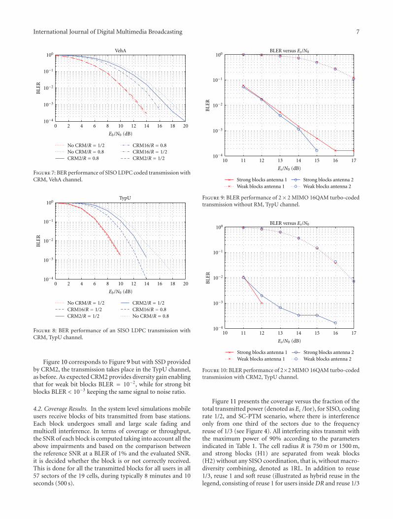
Figure 5 shows the BER performance of SISO and 2 × 2MIMO of an OFDM transmission in three different ITUchannels, namely, the Typical Urban, Flat Rayleigh andVehicular A channels, with different CRM rotation anglesfor Eb/N0 = 8 dB, with turbo coding, coding rate 1/2. Theperformance seems to not depend on the chosen rotation
6 International Journal of Digital Multimedia Broadcasting
Table 1: Simulation parameters for 10 MHz bandwidth.
Transmission BW 10 MHz
CP length (samples) 72, 256
FFT size 1024
Number of occupied sub-carriers 200, 600
Sub-frame duration (ms) 0.5
Sub-carrier spacing (kHz) 15
OFDM symbols per sub-frame 6, 7
Resource blocks 50
Distance attenuation (d = distance inkilometers)
L=122.23 + 34.88 log(d)
Base station power (40 W) 46 dBm
Cell Radius (m) 750, 1500
Cell Layout (hexagonal grid) 3 sectors/site
Shadow fading Log-normal σ = 8 dB
User Mobility Random walk
Multipath fading 3GPP TypU, MBSFN
Max antenna gain (Angular spreadmodel from SCM, including feeder loss)
15 dBi
angle due to the coding rate of 1/2 and the 12 iterationsof the turbo decoder. However, for the TypU channel, theeffect of the CRM signal space diversity which depends onthe chosen angle is observed. According to the results, theFlat channel presents the worst performance followed by theVehA channel and the channel with the best performanceis the TypU. This is explained by the increasing number ofmultipaths and the associated multi-path diversity gain. Forall channels, the BER of MIMO transmission is lower thanSISO where the carried information bit rate of MIMO istwice of SISO’.
Figure 6 shows the BER performance of a MIMO 2 × 2OFDM transmission in the Flat Rayleigh channel with Turbocodes of coding rate 1/2, two different RM matrices with size2, a CRM and an RRM. The performance of both MMSE andMLSO receivers is presented. As expected, the performanceof MLSO receivers is better than the corresponding MMSE.There is a gain of 1.5 dB for the BER = 10−2. There is nodifference in the SSD gain of complex and real matrices aslong as they are optimized.
Figure 7 shows the BLER performance of an SISO OFDMtransmission in the VehA channel with LDPC codes ofdifferent coding rates and two different dimensions of theCRM matrix, MCRM = 2 and MCRM = 16. The signal spacediversity (SSD) gain provided by CRM increases with the sizeof the CRM matrix but is strongly dependent on the codingrate of the LDPC code. The SSD gain is higher for highercoding rates because of the lower coding gain of these codingrates (less channel bit redundancy). When the redundancy ofchannel coding increases, the SSD gain is due to the higherdiversity gains that channel coding can offer compared toSSD.
Figure 8 corresponds to Figure 7 but the transmissiontakes place in the TypU channel instead of VehA. Most of thecomments presented before regarding the VehA channel are
0 10 20 30 40 50 60 70 80 90
Angle (degree)
BE
R
SISO, FlatSISO, VehASISO, TypU
MIMO, FlatMIMO, VehAMIMO, TypU
10−5
10−4
10−3
10−2
10−1
Figure 5: BER performance of turbo-coded transmission withCRM2 for different propagation channels.
0 1 2 3 4 5 6 7 8 9 10
BE
R
Flat rayleigh channel
Eb/N0 (dB)
NoCRM-MLSONoCRM-MMSECRM2-MLSO
CRM2-MMSERRM2-MLSORRM2-MMSE
10−5
10−4
10−3
10−2
10−1
100
Figure 6: BER performance of a MIMO turbo-coded transmissionwith RM, Flat Rayleigh channel.
also valid for TypU channel. However, the comparison of thetwo figures indicates that the performance is better for thetypical urban channel independently of the channel rate. Thegain for BLER = 10−2 is 2 dB for both coding rates.
Figure 9 shows the BLER performance of 2 × 2 MIMOof an OFDM transmission with Hierarchical (H) 16QAM,where the original stream is divided into two QPSK streams,designated as the strong bit blocks and the weak bit blocks.Due to H16QAM and 2×2 MIMO, the bit stream transmittedby each antenna has blocks four times larger than thoseof the previous SISO simulations. As expected, the BLERperformance of strong blocks is much better than the weakblocks’. According to the performance results for the samesignal to noise ratio when strong bit blocks have BLER<10−3,weak bit blocks have BLER = 10−1.
International Journal of Digital Multimedia Broadcasting 7
0 2 4 6 8 10 12 14 16 18 20
Eb/N0 (dB)
VehA
10−4
10−3
10−2
10−1
100
BLE
R
No CRM/R = 1/2No CRM/R = 0.8CRM2/R = 0.8
CRM16/R = 1/2CRM2/R = 1/2
CRM16/R = 0.8
Figure 7: BER performance of SISO LDPC coded transmission withCRM, VehA channel.
10−4
10−3
10−2
10−1
100
BLE
R
TypU
0 2 4 6 8 10 12 14 16 18 20
Eb/N0 (dB)
No CRM/R = 1/2CRM16/R = 1/2CRM2/R = 1/2
CRM2/R = 1/2
No CRM/R = 0.8CRM16/R = 0.8
Figure 8: BER performance of an SISO LDPC transmission withCRM, TypU channel.
Figure 10 corresponds to Figure 9 but with SSD providedby CRM2, the transmission takes place in the TypU channel,as before. As expected CRM2 provides diversity gain enablingthat for weak bit blocks BLER = 10−2, while for strong bitblocks BLER < 10−3 keeping the same signal to noise ratio.
4.2. Coverage Results. In the system level simulations mobileusers receive blocks of bits transmitted from base stations.Each block undergoes small and large scale fading andmulticell interference. In terms of coverage or throughput,the SNR of each block is computed taking into account all theabove impairments and based on the comparison betweenthe reference SNR at a BLER of 1% and the evaluated SNR.it is decided whether the block is or not correctly received.This is done for all the transmitted blocks for all users in all57 sectors of the 19 cells, during typically 8 minutes and 10seconds (500 s).
Es/N0 (dB)
BLER versus Es/N0
10−4
10−3
10−2
10−1
100
BLE
R
10 11 12 13 14 15 16 17
Strong blocks antenna 1Weak blocks antenna 1
Strong blocks antenna 2Weak blocks antenna 2
Figure 9: BLER performance of 2× 2 MIMO 16QAM turbo-codedtransmission without RM, TypU channel.
Es/N0 (dB)
BLER versus Es/N0
10−4
10−3
10−2
10−1
100
BLE
R
10 11 12 13 14 15 16 17
Strong blocks antenna 1Weak blocks antenna 1
Strong blocks antenna 2Weak blocks antenna 2
Figure 10: BLER performance of 2×2 MIMO 16QAM turbo-codedtransmission with CRM2, TypU channel.
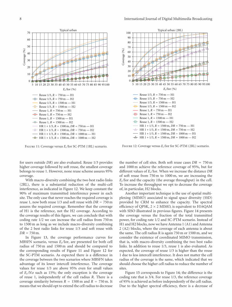
Figure 11 presents the coverage versus the fraction of thetotal transmitted power (denoted as Ec /Ior), for SISO, codingrate 1/2, and SC-PTM scenario, where there is interferenceonly from one third of the sectors due to the frequencyreuse of 1/3 (see Figure 4). All interfering sites transmit withthe maximum power of 90% according to the parametersindicated in Table 1. The cell radius R is 750 m or 1500 m,and strong blocks (H1) are separated from weak blocks(H2) without any SISO coordination, that is, without macro-diversity combining, denoted as 1RL. In addition to reuse1/3, reuse 1 and soft reuse (illustrated as hybrid reuse in thelegend, consisting of reuse 1 for users inside DR and reuse 1/3
8 International Journal of Digital Multimedia Broadcasting
10 20 30 40 50 60 70 80 90 100
Cov
erag
e(%
)
Typical urban
0
10
20
30
40
50
60
70
5 15 25 35 45 55 65 75 85 95
Ec/Ior (%)
Reuse 1/3, R = 750 m — H1Reuse 1/3, R = 750 m — H2Reuse 1/3, R = 1500 m — H1Reuse 1/3, R = 1500 m — H2
Reuse 1, R = 1500 m — H1Reuse 1, R = 1500 m — H2
Reuse 1, R = 750 m — H1Reuse 1, R = 750 m — H2
HR 1 + 1/3, R = 1500 m, DR = 750 m — H1HR 1 + 1/3, R = 1500 m, DR = 750 m — H2HR 1 + 1/3, R = 1500 m, DR = 1000 m — H1HR 1 + 1/3, R = 1500 m, DR = 1000 m — H2
Figure 11: Coverage versus Ec/Ior SC-PTM (1RL) scenario.
for users outside DR) are also evaluated. Reuse 1/3 provideshigher coverage followed by soft reuse, the smallest coveragebelongs to reuse 1. However, none reuse scheme assures 95%coverage.
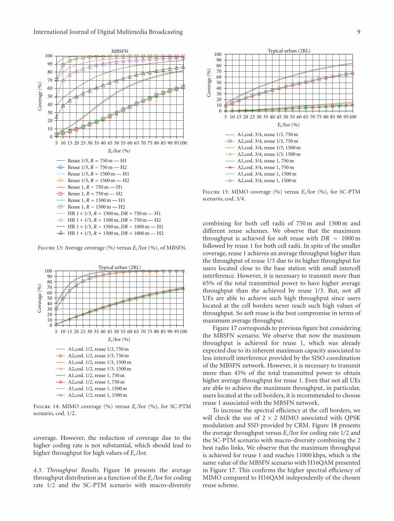
With macro-diversity combining the two best radio links(2RL), there is a substantial reduction of the multi-cellinterference, as indicated in Figure 12. We keep constant the90% of maximum transmitted interference power in eachsite. The only case that never reaches the required coverage isreuse 1, now both reuse 1/3 and soft reuse with DR = 750 massures the required coverage. Remember that the coverageof H1 is the reference, not the H2 coverage. According tothe coverage results of this figure, we can conclude that withcoding rate 1/2 we can increase the cell radius from 750 mto 1500 m as long as we include macro-diversity combiningof the 2 best radio links for reuse 1/3 and soft reuse withDR = 750 m.
In Figure 13, the coverage performance curves forMBSFN scenario, versus Ec/Ior, are presented for both cellradius of 750 m and 1500 m and should be compared tothe corresponding results of Figure 11 and Figure 12 forthe SC-PTM scenario. As expected there is a difference inthe coverage between the two scenarios where MBSFN takesadvantage of its lower intercell interference. The coveragevalues for reuse 1/3 are above 95% even for small valuesof Ec/No such as 15%; the only exception is the coverageof reuse 1, independently of the cell radius R. There is acoverage similarity between R = 1500 m and R = 750 m. Itmeans that we should opt to extend the cell radius to decrease
10 20 30 40 50 60 70 80 90 100
Cov
erag
e(%
)
0
10
20
30
40
50
60
70
5 15 25 35 45 55 65 75 85 95
80
90
100Typical urban (2RL)
Ec/Ior (%)
Reuse 1/3, R = 750 m — H1Reuse 1/3, R = 750 m — H2Reuse 1/3, R = 1500 m — H1Reuse 1/3, R = 1500 m — H2
Reuse 1, R = 1500 m — H1Reuse 1, R = 1500 m — H2
Reuse 1, R = 750 m — H1Reuse 1, R = 750 m — H2
HR 1 + 1/3, R = 1500 m, DR = 750 m — H1HR 1 + 1/3, R = 1500 m, DR = 750 m — H2HR 1 + 1/3, R = 1500 m, DR = 1000 m — H1HR 1 + 1/3, R = 1500 m, DR = 1000 m — H2
Figure 12: Coverage versus Ec/Ior for SC-PTM (2RL) scenario.
the number of cell sites. Both soft reuse cases DR = 750 mand 1000 m achieve the reference coverage of 95%, but fordifferent values of Ec/Ior. When we increase the distance DRof soft reuse from 750 m to 1000 m, we are increasing theEc/Ior and the capacity (the average throughput) in the cell.To increase the throughput we opt to decrease the coverageof, in particular, H2 blocks.
Another important technique is the use of spatial multi-plexing (MIMO) associated to signal space diversity (SSD)provided by CRM to enhance the capacity. The spectralefficiency of QPSK, 2 × 2 MIMO, is equivalent to H16QAMwith SISO illustrated in previous figures. Figure 14 presentsthe coverage versus the fraction of the total transmittedpower, for coding rate 1/2 and SC-PTM scenario. Instead ofH1 and H2 blocks, now we have Antenna 1 (A1) and Antenna2 (A2) blocks, where the coverage of each antenna is aboutthe same. The cell radius R is again 750 m or 1500 m, and weconsider the existence of coordinated MIMO transmission,that is, with macro-diversity combining the two best radiolinks. In addition to reuse 1/3, reuse 1 is also evaluated. Asexpected, the coverage of reuse 1/3 is higher than the reuse1 due to less intercell interference. It does not matter the cellradius of the coverage is the same, which indicated that weshould choose the higher cell radius to reduce the number ofsites.
Figure 15 corresponds to Figure 14; the difference is thecoding rate that is 3/4. For reuse 1/3, the reference coverageof 95% is achieved as before independently of the cell radius.Due to the higher spectral efficiency, there is a decrease of
International Journal of Digital Multimedia Broadcasting 9
10 20 30 40 50 60 70 80 90 100
Cov
erag
e(%
)
0
10
20
30
40
50
60
70
5 15 25 35 45 55 65 75 85 95
80
90
100MBSFN
Ec/Ior (%)
Reuse 1/3, R = 750 m — H1Reuse 1/3, R = 750 m — H2Reuse 1/3, R = 1500 m — H1Reuse 1/3, R = 1500 m — H2
Reuse 1, R = 1500 m — H1Reuse 1, R = 1500 m — H2
Reuse 1, R = 750 m — H1Reuse 1, R = 750 m — H2
HR 1 + 1/3, R = 1500 m, DR = 750 m — H1HR 1 + 1/3, R = 1500 m, DR = 750 m — H2HR 1 + 1/3, R = 1500 m, DR = 1000 m — H1HR 1 + 1/3, R = 1500 m, DR = 1000 m — H2
Figure 13: Average coverage (%) versus Ec/Ior (%), of MBSFN.
10 20 30 40 50 60 70 80 90 100
Cov
erag
e(%
)
010203040506070
5 15 25 35 45 55 65 75 85 95
8090
100Typical urban (2RL)
A1,cod. 1/2, reuse 1/3, 750 mA2,cod. 1/2, reuse 1/3, 750 mA1,cod. 1/2, reuse 1/3, 1500 mA2,cod. 1/2, reuse 1/3, 1500 mA1,cod. 1/2, reuse 1, 750 mA2,cod. 1/2, reuse 1, 750 mA1,cod. 1/2, reuse 1, 1500 mA2,cod. 1/2, reuse 1, 1500 m
Ec/Ior (%)
Figure 14: MIMO coverage (%) versus Ec/Ior (%), for SC-PTMscenario, cod. 1/2.
coverage. However, the reduction of coverage due to thehigher coding rate is not substantial, which should lead tohigher throughput for high values of Ec/Ior.
4.3. Throughput Results. Figure 16 presents the averagethroughput distribution as a function of the Ec/Ior for codingrate 1/2 and the SC-PTM scenario with macro-diversity
10 20 30 40 50 60 70 80 90 100
Cov
erag
e(%
)
010203040506070
5 15 25 35 45 55 65 75 85 95
8090
100Typical urban (2RL)
A1,cod. 3/4, reuse 1/3, 750 mA2,cod. 3/4, reuse 1/3, 750 mA1,cod. 3/4, reuse 1/3, 1500 mA2,cod. 3/4, reuse 1/3, 1500 mA1,cod. 3/4, reuse 1, 750 mA2,cod. 3/4, reuse 1, 750 mA1,cod. 3/4, reuse 1, 1500 mA2,cod. 3/4, reuse 1, 1500 m
Ec/Ior (%)
Figure 15: MIMO coverage (%) versus Ec/Ior (%), for SC-PTMscenario, cod. 3/4.
combining for both cell radii of 750 m and 1500 m anddifferent reuse schemes. We observe that the maximumthroughput is achieved for soft reuse with DR = 1000 mfollowed by reuse 1 for both cell radii. In spite of the smallercoverage, reuse 1 achieves an average throughput higher thanthe throughput of reuse 1/3 due to its higher throughput forusers located close to the base station with small intercellinterference. However, it is necessary to transmit more than65% of the total transmitted power to have higher averagethroughput than the achieved by reuse 1/3. But, not allUEs are able to achieve such high throughput since userslocated at the cell borders never reach such high values ofthroughput. So soft reuse is the best compromise in terms ofmaximum average throughput.
Figure 17 corresponds to previous figure but consideringthe MBSFN scenario. We observe that now the maximumthroughput is achieved for reuse 1, which was alreadyexpected due to its inherent maximum capacity associated toless intercell interference provided by the SISO coordinationof the MBSFN network. However, it is necessary to transmitmore than 45% of the total transmitted power to obtainhigher average throughput for reuse 1. Even that not all UEsare able to achieve the maximum throughput, in particular,users located at the cell borders, it is recommended to choosereuse 1 associated with the MBSFN network.
To increase the spectral efficiency at the cell borders, wewill check the use of 2 × 2 MIMO associated with QPSKmodulation and SSD provided by CRM. Figure 18 presentsthe average throughput versus Ec/Ior for coding rate 1/2 andthe SC-PTM scenario with macro-diversity combining the 2best radio links. We observe that the maximum throughputis achieved for reuse 1 and reaches 11000 kbps, which is thesame value of the MBSFN scenario with H16QAM presentedin Figure 17. This confirms the higher spectral efficiency ofMIMO compared to H16QAM independently of the chosenreuse scheme.

10 International Journal of Digital Multimedia Broadcasting
0
1000
2000
3000
4000
5000
6000
7000
10 20 30 40 50 60 70 80 90 1005 15 25 35 45 55 65 75 85 95
Th
rou
ghpu
t(k
bps)
Typical Urban (2RL)
Reuse 1/3, R = 750 mReuse 1/3, R = 1500 mReuse 1, R = 750 mReuse 1, R = 1500 mHR 1 + 1/3, R = 1500 m, DR = 750 mHR 1 + 1/3, R = 1500 m, DR = 1000 m
Ec/Ior (%)
Figure 16: Throughput versus Ec/Ior for SC-PTM (2RL) scenario.
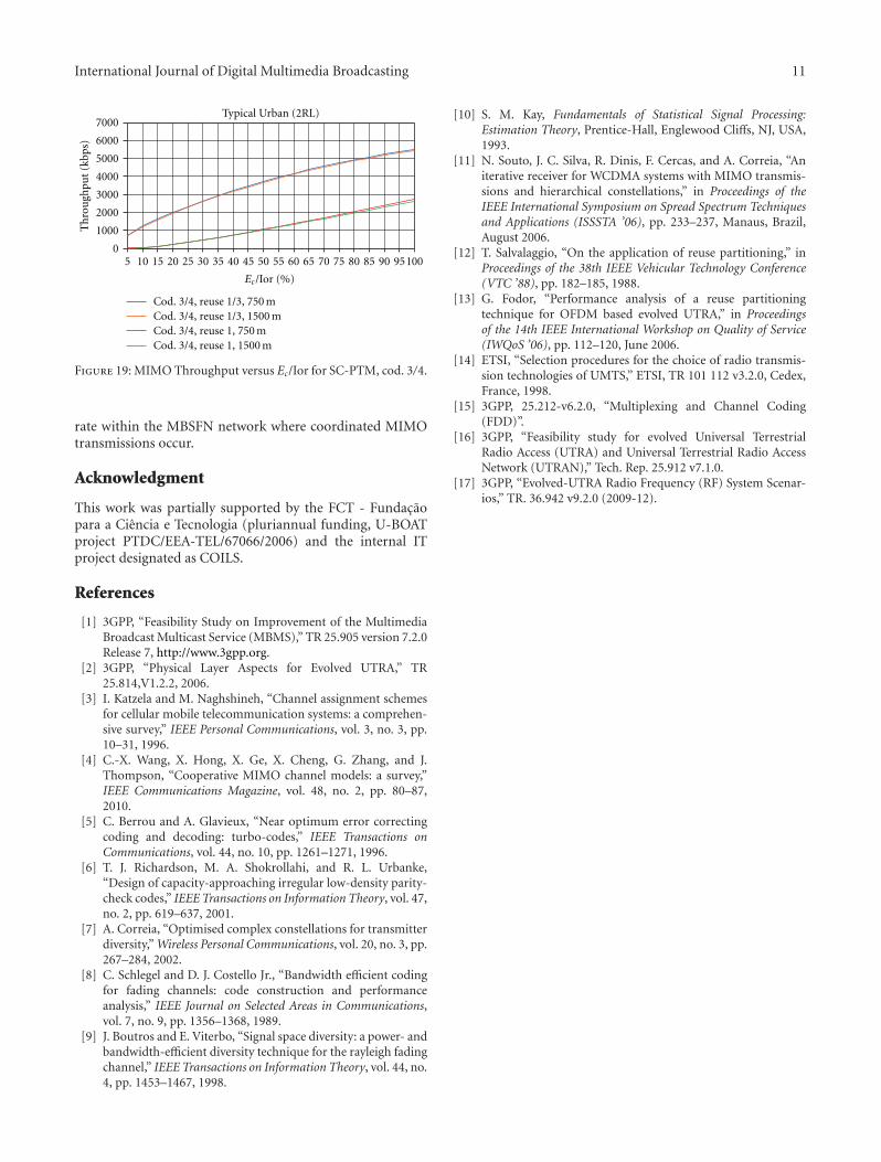
Figure 19 corresponds to Figure 18, the difference isthe coding rate of 3/4. As expected for reuse 1 withthe highest fraction of transmitted power, the throughputreaches 12400 kbps. In spite of the lower coverage, theaverage throughput is higher with coding rate 3/4, but it doesnot reach 1.5 times the throughput of coding rate 1/2. Thisconfirms that with coding rate 3/4, users at the cell bordershave less throughput than those that are located closer to theBS.
To increase further the spectral efficiency at cell borders,it is suggested to keep the coding rate of 3/4 and use thecoordinated MIMO transmissions provided by the MBSFNnetwork.
5. Conclusions
In this paper, we have analyzed interference coordinationmethods for Evolved-Multimedia Broadcast/Multicast Ser-vice (E-MBMS) in Long-Term Evolution Advanced (LTE-A). In addition, we introduce signal space diversity basedon Rotation Matrices (RM) known to provide good per-formance gains over uncorrelated Rayleigh fading channels.OFDM/OFDMA chosen for E-MBMS with the use of RMand both single and multiple antenna transmissions areassociated with Turbo or LDPC codes. We have consideredan MMSE (Minimum Mean Squared Error) equalizer, anda Maximum Likelihood Soft Output criterion (MLSO) aspossible receivers.
We conclude that for higher coding rates SISO OFDMsystems, the introduction of RM provides signal spacediversity gain, for both Turbo and LDPC codes that increasewith the size of the rotation matrices, independently ofthe rotation angle chosen. For lower coding rates, the
0
2000
4000
6000
10 20 30 40 50 60 70 80 90 1005 15 25 35 45 55 65 75 85 95
Th
rou
ghpu
t(k
bps)
Reuse 1/3, R = 750 mReuse 1/3, R = 1500 mReuse 1, R = 750 mReuse 1, R = 1500 mHR 1 + 1/3, R = 1500 m, DR = 750 mHR 1 + 1/3, R = 1500 m, DR = 1000 m
8000
10000
12000MBSFN
Ec/Ior (%)
Figure 17: Throughput versus Ec/Ior for MBSFN scenario.
0
1000
2000
3000
4000
5000
6000
7000
10 20 30 40 50 60 70 80 90 1005 15 25 35 45 55 65 75 85 95
Th
rou
ghpu
t(k
bps)
Typical Urban (2RL)8000
Cod. 1/2, reuse 1/3, 750 mCod. 1/2, reuse 1/3, 1500 mCod. 1/2, reuse 1, 750 mCod. 1/2, reuse 1, 1500 m
Ec/Ior (%)
Figure 18: MIMO Throughput versus Ec/Ior for SC-PTM, cod. 1/2.
introduction of RM only provides diversity gain for turbocodes and is smaller than with higher coding rates.
Based on the average coverage and throughput results,for the SC-PTM scenario, the use of soft reuse, that is, amixture of reuse 1 for users closer to BS and reuse 1/3 forusers at the cell borders is recommended. It is also suggestedto apply some coordination between the point-to-multipointtransmissions of adjacent BSs. For the MBSFN scenario, werecommend the use of reuse 1 due to its best compromisebetween coverage and maximum achieved throughput.
The introduction of signal space diversity and spatialmultiplexing 2×2 MIMO enables enhancing the spectral effi-ciency at the cell borders of SC-PTM. Further enhancementof the spectral efficiency is possible increasing the coding
International Journal of Digital Multimedia Broadcasting 11
0
1000
2000
3000
4000
5000
6000
7000
10 20 30 40 50 60 70 80 90 1005 15 25 35 45 55 65 75 85 95
Th
rou
ghpu
t(k
bps)
Typical Urban (2RL)
Cod. 3/4, reuse 1/3, 750 mCod. 3/4, reuse 1/3, 1500 mCod. 3/4, reuse 1, 750 mCod. 3/4, reuse 1, 1500 m
Ec/Ior (%)
Figure 19: MIMO Throughput versus Ec/Ior for SC-PTM, cod. 3/4.
rate within the MBSFN network where coordinated MIMOtransmissions occur.
Acknowledgment
This work was partially supported by the FCT - Fundacaopara a Ciencia e Tecnologia (pluriannual funding, U-BOATproject PTDC/EEA-TEL/67066/2006) and the internal ITproject designated as COILS.
References
[1] 3GPP, “Feasibility Study on Improvement of the MultimediaBroadcast Multicast Service (MBMS),” TR 25.905 version 7.2.0Release 7, http://www.3gpp.org.
[2] 3GPP, “Physical Layer Aspects for Evolved UTRA,” TR25.814,V1.2.2, 2006.
[3] I. Katzela and M. Naghshineh, “Channel assignment schemesfor cellular mobile telecommunication systems: a comprehen-sive survey,” IEEE Personal Communications, vol. 3, no. 3, pp.10–31, 1996.
[4] C.-X. Wang, X. Hong, X. Ge, X. Cheng, G. Zhang, and J.Thompson, “Cooperative MIMO channel models: a survey,”IEEE Communications Magazine, vol. 48, no. 2, pp. 80–87,2010.
[5] C. Berrou and A. Glavieux, “Near optimum error correctingcoding and decoding: turbo-codes,” IEEE Transactions onCommunications, vol. 44, no. 10, pp. 1261–1271, 1996.
[6] T. J. Richardson, M. A. Shokrollahi, and R. L. Urbanke,“Design of capacity-approaching irregular low-density parity-check codes,” IEEE Transactions on Information Theory, vol. 47,no. 2, pp. 619–637, 2001.
[7] A. Correia, “Optimised complex constellations for transmitterdiversity,” Wireless Personal Communications, vol. 20, no. 3, pp.267–284, 2002.
[8] C. Schlegel and D. J. Costello Jr., “Bandwidth efficient codingfor fading channels: code construction and performanceanalysis,” IEEE Journal on Selected Areas in Communications,vol. 7, no. 9, pp. 1356–1368, 1989.
[9] J. Boutros and E. Viterbo, “Signal space diversity: a power- andbandwidth-efficient diversity technique for the rayleigh fadingchannel,” IEEE Transactions on Information Theory, vol. 44, no.4, pp. 1453–1467, 1998.
[10] S. M. Kay, Fundamentals of Statistical Signal Processing:Estimation Theory, Prentice-Hall, Englewood Cliffs, NJ, USA,1993.
[11] N. Souto, J. C. Silva, R. Dinis, F. Cercas, and A. Correia, “Aniterative receiver for WCDMA systems with MIMO transmis-sions and hierarchical constellations,” in Proceedings of theIEEE International Symposium on Spread Spectrum Techniquesand Applications (ISSSTA ’06), pp. 233–237, Manaus, Brazil,August 2006.
[12] T. Salvalaggio, “On the application of reuse partitioning,” inProceedings of the 38th IEEE Vehicular Technology Conference(VTC ’88), pp. 182–185, 1988.
[13] G. Fodor, “Performance analysis of a reuse partitioningtechnique for OFDM based evolved UTRA,” in Proceedingsof the 14th IEEE International Workshop on Quality of Service(IWQoS ’06), pp. 112–120, June 2006.
[14] ETSI, “Selection procedures for the choice of radio transmis-sion technologies of UMTS,” ETSI, TR 101 112 v3.2.0, Cedex,France, 1998.
[15] 3GPP, 25.212-v6.2.0, “Multiplexing and Channel Coding(FDD)”.
[16] 3GPP, “Feasibility study for evolved Universal TerrestrialRadio Access (UTRA) and Universal Terrestrial Radio AccessNetwork (UTRAN),” Tech. Rep. 25.912 v7.1.0.
[17] 3GPP, “Evolved-UTRA Radio Frequency (RF) System Scenar-ios,” TR. 36.942 v9.2.0 (2009-12).

International Journal of
AerospaceEngineeringHindawi Publishing Corporationhttp://www.hindawi.com Volume 2010
RoboticsJournal of
Hindawi Publishing Corporationhttp://www.hindawi.com Volume 2014
Hindawi Publishing Corporationhttp://www.hindawi.com Volume 2014
Active and Passive Electronic Components
Control Scienceand Engineering
Journal of
Hindawi Publishing Corporationhttp://www.hindawi.com Volume 2014
International Journal of
RotatingMachinery
Hindawi Publishing Corporationhttp://www.hindawi.com Volume 2014
Hindawi Publishing Corporation http://www.hindawi.com
Journal ofEngineeringVolume 2014
Submit your manuscripts athttp://www.hindawi.com
VLSI Design
Hindawi Publishing Corporationhttp://www.hindawi.com Volume 2014
Hindawi Publishing Corporationhttp://www.hindawi.com Volume 2014
Shock and Vibration
Hindawi Publishing Corporationhttp://www.hindawi.com Volume 2014
Civil EngineeringAdvances in
Acoustics and VibrationAdvances in
Hindawi Publishing Corporationhttp://www.hindawi.com Volume 2014
Hindawi Publishing Corporationhttp://www.hindawi.com Volume 2014
Electrical and Computer Engineering
Journal of
Advances inOptoElectronics
Hindawi Publishing Corporation http://www.hindawi.com
Volume 2014
The Scientific World JournalHindawi Publishing Corporation http://www.hindawi.com Volume 2014
SensorsJournal of
Hindawi Publishing Corporationhttp://www.hindawi.com Volume 2014
Modelling & Simulation in EngineeringHindawi Publishing Corporation http://www.hindawi.com Volume 2014
Hindawi Publishing Corporationhttp://www.hindawi.com Volume 2014
Chemical EngineeringInternational Journal of Antennas and
Propagation
International Journal of
Hindawi Publishing Corporationhttp://www.hindawi.com Volume 2014
Hindawi Publishing Corporationhttp://www.hindawi.com Volume 2014
Navigation and Observation
International Journal of
Hindawi Publishing Corporationhttp://www.hindawi.com Volume 2014
DistributedSensor Networks
International Journal of


![ASecureandStableMulticastOverlayNetworkwithLoad ...downloads.hindawi.com › journals › ijdmb › 2012 › 540801.pdf · member failure [15]. ALM mesh can be regarded as the superposed](https://img.pdfslide.net/doc/110x75/5f11a2894843b6539e7751de/asecureandstablemulticastoverlaynetworkwithload-a-journals-a-ijdmb-a-2012.jpg)