Embed Size (px)
Citation preview

DISTRIBUTION STATEMENT A: Approved for public release; distribution is unlimited.
NONRESIDENT
TRAINING COURSE
Interior Communications Electrician, Volume 3
NAVEDTRA 14122
IMPORTANT
Any future change to this course can be found at https://www.advancement.cnet.navy.mil, under Products.
You should routinely check this web site.

PREFACE
About this course: This is a self-study course. By studying this course, you can improve your professional/military knowledge, as well as prepare for the Navywide advancement-in-rate examination. It contains subject matter about day-to-day occupational knowledge and skill requirements and includes text, tables, and illustrations to help you understand the information. An additional important feature of this course is its reference to useful information in other publications. The well-prepared Sailor will take the time to look up the additional information. Training series information: This is Volume 3 of a series. For a listing and description of the entire series, see NAVEDTRA 12061, Catalog of Nonresident Training Courses, at https://www.advancement.cnet.navy.mil. History of the course: • May 1992: Original edition released. Authored by ICCS Bert A. Parker. • Oct 2003: Administrative update released. Technical content was reviewed by ICC(SW) Curtis Fox.
No change in technical content.
Published by NAVAL EDUCATION AND TRAINING
PROFESSIONAL DEVELOPMENT AND TECHNOLOGY CENTER https://www.cnet.navy.mil/netpdtc
POINTS OF CONTACT ADDRESS • E-mail: [email protected] • Phone:
Toll free: (877) 264-8583 Comm: (850) 452-1511/1181/1859 DSN: 922-1511/1181/1859 FAX: (850) 452-1370
COMMANDING OFFICER NETPDTC N331 6490 SAUFLEY FIELD ROAD PENSACOLA FL 32559-5000
Technical content assistance. Contact a Subject Matter Expert at https://www.advancement.cnet.navy.mil/welcome.asp, under Exam Info, Contact Your Exam Writer.
NAVSUP Logistics Tracking Number 0504-LP-026-7840

TABLE OF CONTENTS
CHAPTER PAGE
1. Technical Administration....................................................................................... 1-1
2. Quality Assurance .................................................................................................. 2-1
3. Ship's Drawings and Diagrams .............................................................................. 3-1
4. Maintenance ........................................................................................................... 4-1
APPENDIX
I. Glossary ................................................................................................................. AI-1
II. References used to develop this NRTC ................................................................. AII-1
INDEX ............................................................................................................................................ INDEX-1
ASSIGNMENT QUESTIONS follow Index.

CHAPTER 1
TECHNICAL ADMINISTRATION
LEARNING OBJECTIVES
Upon completion of this chapter, you will be able to do the following:
1. Identify the steps in planning and scheduling work 2. Describe the steps in preparing and reviewingand in assigning tasks and duties. casualty reports (CASREPs), casualty corrections
(CASCORs), and situation reports (SITREPs).
INTRODUCTION
As an IC Electrician First Class or Chief, you canexpect to spend much more time on administrative andsupervisory duties. As an administrator, you will assigntasks and fill out required reports and schedules. As asupervisor, you will oversee the work and make sure itis done correctly and on time.
As an IC1 or ICC, you maybe required to organizeand supervise an IC shop aboard ship. This chapter willgive you insight into the areas of shop supervision andreport preparation and will provide you with useful toolsthat will help you fulfill your role as a shop supervisor.Some areas of shop supervision are not covered in thischapter. But, you may find information about these areasin other publications, such as the Ship’s Maintenanceand Material Management (3-M) Manual,OPNAVINST 4790.4B; Navy Occupational Safety andHealth (NAVOSH) Program Manual, OPNAVINST5100.23B; Navy Safety Precautions for Forces Afloat,OPNAVINST 5100.19B; and Engineering Admin-istration, NAVEDTRA 10858-F.
SHOP SUPERVISION
As an ICI or ICC, one of your more important roleswill be as a supervisor or leader. You will be responsiblefor planning and organizing work and supervising anddirecting personnel.
As the IC1 or ICC in charge of an IC shop, youshould fully appreciate and understand theresponsibility you hold as a member of a shipboardorganization and be able to identify each of your dutieswith respect to any assigned job.
The following list includes the duties andresponsibilities that are common to most shopsupervisors:
Getting the right person on the job at the righttime
Using tools and materials as economically aspossible
Preventing conditions that might cause accidents
Maintaining discipline
Keeping records and preparing reports
Maintaining the quality and quantity of repairwork
Planning and scheduling repair work
Training personnel
Requisitioning tools, equipment, and materials
Inspecting and maintaining tools and equipment
Giving orders and directions
Cooperating with others
Checking and inspecting completed repairs
Promoting teamwork
MAINTENANCE AND REPAIR
To fulfill your administrativeresponsibilities in connection with
and supervisorymaintenance and
repair, you must have the ability to plan. By followingprescribed procedures of the 3-M Systems, maintenance
1-1
planning should be easy. But some administrative andsupervisory duties will not be affected by the 3-MSystems. You will always find some engine-roommaintenance and repair work that just won’t fit into aschedule, but must be done whenever the opportunityarise. So, in addition to having the ability to plan, youmust also have a certain amount of flexibility so you canalter your plans to fit the existing circumstances. A fewadministrative and supervisory considerations thatapply to maintenance and repair are discussed in thefollowing sections.
The 3-M Systems, like any other system or program,is only as good as the personnel who make it work. Yourrole in the 3-M Systems, as an IC1 or ICC, will includethe training of lower-rated personnel in its use. Thesepersonnel must be trained in the scheduling andsupervision of maintenance. As a supervisor, you shouldkeep abreast of all developments and changes to the 3-MSystems. Details on the 3-M Systems and changesrelated to it are available in the Ship’s Maintenance andMaterial Management (3-M) Manual, OPNAVINST4790.4B.
PLANNING
Careful planning is necessary to keep an IC shoprunning efficiently and productively. Planning results inthe proper employment of your people. Today’s ICElectricians are well-trained technicians, who have theright to expect their service to be employed in an orderlyfashion with proper organization and supervision.
The weekly PMS work schedule is a proven methodof ensuring proper personnel employment. Themechanics of the PMS system allows the supervisor toensure that there is adequate time for training, ship’sevolutions, recreation, and so on. Most important inusing PMS is the supervisor’s familiarity with the ship’sschedule on a given day. You must “get the word” so thatyou can plan your people’s work. Therefore, getting theword is your responsibility. The proper use of the weeklyPMS work schedule will, in a short time, result in moretraining and less equipment downtime. Your subgroupleaders must use foresight in planning this schedule. Inparticular, avoid stretching your supervisory personneltoo thin. A person cannot provide adequate supervisionto the installation of an electromagnetic log (sword) andthe removal of a wind indicator (bird) at the same time.
The job cards used in the PMS system can be usefulmaintenance aids on any ship, provided they first aretailored to your ship via the PMS feedback report. Yourparticular salinity system may have one or two peculiar
steps that must be taken in removing a cell. The cardsare made out for a standard system, and modification ispossible. Job cards do, however, give properlysequenced procedures for job performance and shouldbe followed
Emergency planning should be done when possiblein a checkoff list fashion. By analyzing your needs and,where possible, writing the job out in procedural steps,you may learn many things. On jobs that affect the ship’smaneuverability, the written procedural method isparticularly effective in getting the right conditions setup and help lined up. By going over the replacement ofa synchro transmitter in the propeller revolutionindicator circuit step by step with your division officer,you may find that you can have the shaft stopped, thusaiding in the repair of the synchro transmitter.
You must ensure that all personnel are informedabout the nature and scheduling of repairs. Therealignment of a gyrocompass synchro amplifier maycause havoc for the ETs, FTs, STs, and OSs. However,if you inform the group supervisors ahead of time, theycan act to prevent or lessen trouble in their equipment.Emergency repairs require the permission of the OOD.Your division officer should always be notified. Youmust remember that the IC group is not an end untoitself, but rather a member of a team.
An important phase of planning your work is theorganizing of your personnel to accomplish their task.This is, however, a ship-to-ship problem, with subgroupsupervisors varying in technical background andsubordinate personnel varying in number.
It is imperative that a team spirit is developed inyour personnel and that you maintain something of acompetitive spirit. Through proper employment ofcompetition, the standard of the IC group at work, atquarters, and in the compartment can be maintainedabove that of the other engineers. By the nature of thework involved, IC Electricians should be able tomaintain their berthing spaces and their uniforms in topcondition.
There is often a reluctance on the part of manytechnicians to make the change to technical supervisor.As the leading IC Electrician, you must ensure that thischange takes place. You can do this by assigning part ofthe supervisory load to personnel who have advanced inan orderly fashion. Take care to provide up-to-daterecords that will help them on the new assignment. Besure that time is allowed for them to become familiarwith their new responsibility. Take them into your
1-2
confidence regarding planning and professionalmatters.
You, as a supervisor, must be available to yoursubgroup supervisors, and they, in turn, must beavailable to their subordinates. Ensure that all requestscome up the line in proper fashion. Also, make sure thatthey go down the line in the same fashion. Avoidcollecting request chits at quarters before your pettyofficers have a chance to consider them. Don’t let yourpersonnel get their replies in the log room. Pick them upyourself and return them to the subgroup supervisor.This is a small item, but it reinforces the chain ofcommand. Except when dealing with a severe personalproblem, always ask subgroup supervisors toaccompany any of their personnel with whom you mustconverse, rather than have them go it alone. This shouldgive them confidence in their supervisor and you thebenefit of the supervisor’s views.
As a supervisor, you must be aware of each job asit is worked by your personnel. Show an active interestin the personnel under you. If you do not periodicallycheck on your subordinates’ work, you will soonbecome aware of problems at a later time. As asupervisor, you must, while keeping your hand on thejob, keep it off the screwdriver.
INFORMATION ON INCOMING WORK
Job orders will generally be received in the shopseveral days in advance. You should start planning assoon as possible to gain an advantage of time. Much ofyour planning may be done before the work is deliveredto the work center.
PRIORITY OF JOBS
In planning and scheduling work you will have togive careful consideration to the priority of each joborder. Priorities are generally classified as urgent,routine, and deferred.
The majority of job orders will have the routinepriority assigned to them. Routine jobs make up thenormal workload of the work center, and they must becarefully planned and scheduled so that the dailyorganization and production can be maintained at a highstandard.
Urgent-priority jobs require immediate planningand scheduling. Lower-priority jobs may have to be setaside so that urgent jobs can be done.
Deferred jobs do not present much of a problem.They are usually accomplished when the workload ofthe shop is light and there are few jobs to be done.
When determining the priority of a task, you shouldconsider the following information:
The ship’s schedule and the effect theequipment will have on the ability of the ship toperform its mission
Whether the work requires someone with specialqualifications
Whether or not all the required parts and materialare available
The work center supervisor should review the workfor the week with the division officer and determine thejobs that need to be accomplished right away (priority1) and those that can be done at a later date (priority 2).The work that cannot be completed due to the lack ofmaterial or trained personnel should then be deferred torequest material or outside assistance (priority 3). Whenwork gets sent to an outside activity, you should fill outa Ship’s Maintenance Action Form, OPNAV 4790/2K(fig. 1-1). When filling out this form, you should fill outall the proper blocks as completely as possible. Refer tofigure 1-1 to determine what blocks you must fill out.
You must provide as much technical documentationas possible. You may have to fill out a SupplementalForm, OPNAV 4790/2L (fig. 1-2), when requirementsare not covered by technical documentation.
If you cannot complete a priority 1 task because ofship’s schedule or other reasons, you should work on apriority 2 task. In this manner, the shop will be able toaccomplish assigned tasks in a timely and effectivemanner.
SCHEDULING OF WORK
The main object in the scheduling of work is to havethe work flow smoothly and without delay, since losttime between jobs lowers the overall efficiency of thework center. Because of the variety of jobs you and yourpersonnel will be required to perform, specific workschedules must be prepared to ensure that all work iscompleted. Although these schedules list specific jobassignments, they must be flexible enough to allow forchanges in priorities, transfer of personnel, temporarybreakdowns of equipment, unscheduled ship drills, orany emergency that may arise.
You may have to change the schedule of work in thework center when new high-priority jobs come in.
1-3

Figure 1-1.-Ship’s Maintenance Action Form (2-KILO).
1-4
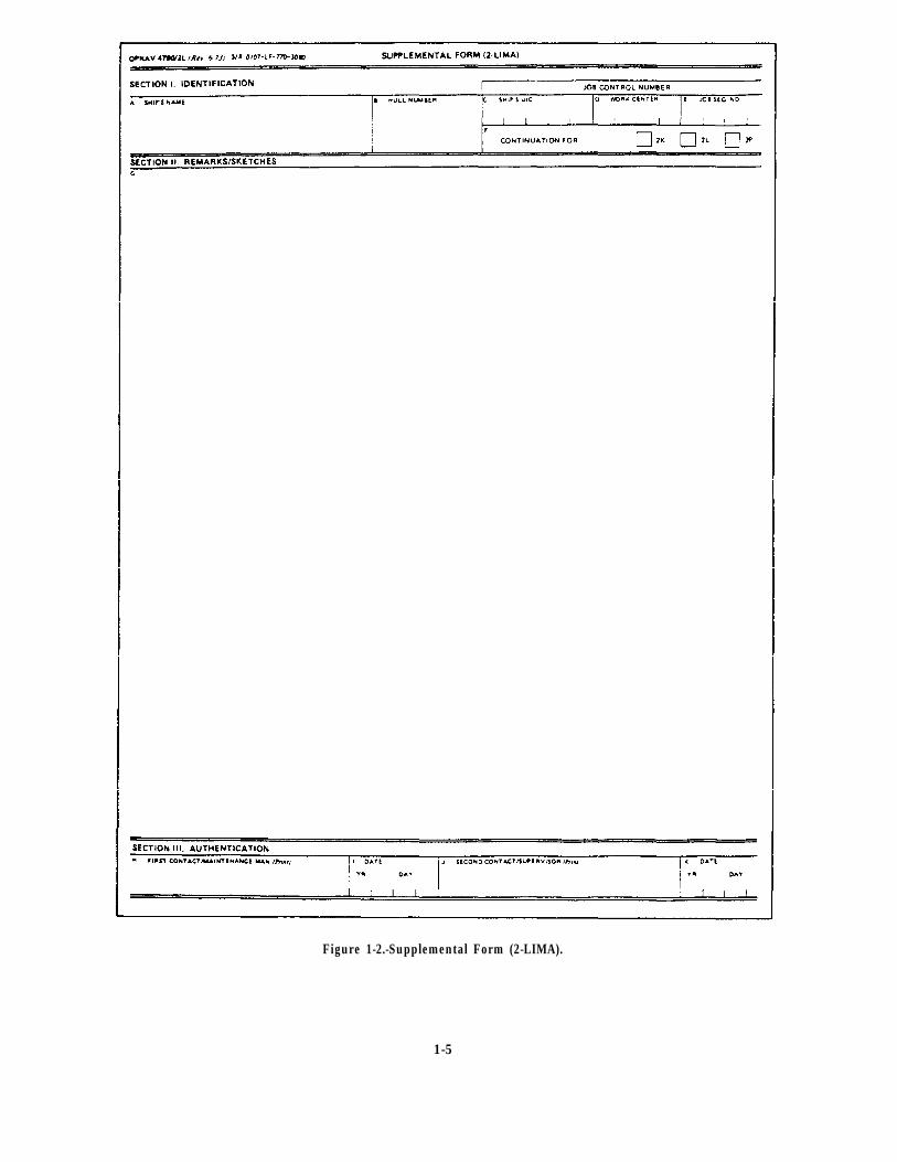
Figure 1-2.-Supplemental Form (2-LIMA).
1-5
Sometimes you may have to set other work asidetemporarily y until these urgent jobs are completed.
Careful planning is required to keep up with allshipboard maintenance and repair work. Some of thefactors that you should consider when schedulingmaintenance and repair work are as follows:
– Size up each job before you let anyone startworking on it. Check the applicable maintenancerequirement cards (MRCs) so that you will knowexactly what needs to be done. Also, check allapplicable drawings and manufacturer’stechnical manuals.
– Check on materials before you start. Be sure thatall required materials are available before yourpersonnel start working on any job. Do not over-look small items, such as nuts, bolts, washers,packing and gasket materials, tools, andmeasuring devices. A good deal of labor can besaved by the simple process of checking on theavailability of materials before a job is actuallystarted. An inoperable piece of equipment canbecome a nuisance and a safety hazard if it isspread around the room in bits and pieces whileyou wait for the arrival of repair parts ormaterials.
– Check on the priority of the job and of all otherwork that needs to be done before scheduling anyjob.
– When assigning tasks, carefully consider thecapabilities and experience of your personnel. Asa rule, the more complicated jobs should be givento the more skilled and more experienced people.When possible, however, less experiencedpersonnel should be given difficult tasks to dounder supervision so that they may gainexperience in such tasks. Be sure that the personwho is going to do a job is given as muchinformation as necessary. An experienced personmay need only a drawing and a general statementabout the nature of the job. A less experiencedperson is likely to require additional instructionsand, as a rule, closer supervision.
Keep track of the work as it is being done. Inparticular, check to be sure that the proper materials andparts are being used, that the job is properly laid out orset up, that all tools and equipment are being correctlyused, and that all safety precautions are being followed.
After a job has been completed, make a carefulinspection to be sure that everything has been done
correctly and that all final details have been taken careof. Check to be sure that all necessary records or reportshave been prepared. These job inspections serve at leasttwo very important purposes: first, they are used to makesure that the work has been completed in a satisfactorymanner; and second, they provide for an evaluation ofthe skills and knowledge of the person who has done thework. Do not overlook the training aspects of a jobinspection. When your inspection of a completed jobreveals any defects or flaws, be sure to explain what iswrong, why it is wrong, and how to avoid similarmistakes in the future.
ESTIMATING WORK
You will often be required to estimate the amountof time, the number of personnel, and the amount ofmaterial that is needed for repair work. Actually, youare making some kind of estimate every time you planand start a job, as you consider such questions as Howlong will it take? Who can best do the job? Howmany people will be needed? Are all necessarymaterials available?
However, there is one important differencebetween the estimates you make for your own use andthose you make when your division officer asks forestimates. When you give an estimate to someone inauthority over you, you cannot tell how far up the linethis information will go. It is possible that anyestimate you give to your division officer could affectthe operational schedule of the ship. It is essential,therefore, that such estimates be as accurate as youcan possibly make them.
Many of the factors that apply to the scheduling ofall maintenance and repair work apply also to estimatingthe time for a particular repair job. You cannot make areasonable estimate until you have sized up the job,checked on the availability of skilled personnel andmaterials, and checked on the priority of the various jobsfor which you are responsible. To make an accurateestimate of the time required to complete a specificrepair job, you must consider (1) what part of the workmust be done by other shops, and (2) what interruptionsand delays may occur. Although these factors are alsoimportant in the routine scheduling of maintenance andrepair world they are also important when you aremaking estimates of time that may affect the operationalschedule of the ship.
If part of the job must be done by other shops,you must consider not only the time actuallyrequired by these other shops, but also the time that
1-6
may be lost if one of them holds up your work and thetime spent to transport material between shops. Eachshop should make a separate estimate, and theestimates should be combined to get the finalestimate. Do not try to estimate the time that willbe required by other personnel. Attempting toestimate what someone else can do is risky becauseyou cannot possibly have enough information tomake an accurate estimate.
Consider all the interruptions that will cause delays,over and above the time required for the work itself.Such things as drills, inspections, field days, andworking parties have quite an effect on the number ofpeople who will be available to work on the job at anygiven time.
Estimating the number of personnel required for acertain repair job is, obviously, closely related toestimating time. You will have to consider not only thenature of the job and the number of people available, butalso the maximum number of people who can workEFFECTIVELY on a job or on part of the job at the sametime. On many jobs there is a natural limit to the numberof people who can work effectively at any one time. Ona job of this kind, doubling the number of personnel willnot cut the time in half; instead, it will merely result inconfusion and aimless milling around.
The best way to estimate the time and the numberof personnel needed to do a job is to divide the total jobinto the various phases or steps that will have to be done,and then estimate the time and personnel required foreach step, taking in consideration the ship’s scheduleduring each step. One way of getting a handle on whatis going on during each step is to consult the ship’smaster training schedule and the monthly training plan.Taking all this miscellaneous time into considerationwill give you an accurate estimate of time required toaccomplish the job.
Estimating the materials required for a repair job isoften more difficult than estimating the time and laborrequired for the job. Although your own experience willbe your best guide for this kind of estimating, a fewgeneral considerations should be noted:
– Keep accurate records of all materials and toolsused in any major repair job. These records servetwo purposes: first, they provide a means ofaccounting for materials used; and second, theyprovide a guide for estimating materials that willbe used for similar jobs in the future.
– Before starting any repair job, plan the jobcarefully and in detail. Make full use of
manufacturers’ technical manuals, blueprints,drawings, and any other available information.Try to find out in advance all the tools andmaterials needed for the job.
Make a reasonable allowance for waste whencalculating the amount of material you willneed.
MATERIALS AND REPAIR PARTS
The responsibility for maintaining adequate stocksof engine-room repair parts and repair materials belongsat least as much to you as it does to the supplydepartment. The duties of the supply officer are to buy,receive, stow, issue, and account for most types of storesrequired for the support of the ship. However, the supplyofficer is not the prime user of repair parts and repairmaterials; the initiative for maintaining adequate stocksof repair materials, parts, and equipment must comefrom the personnel who are going to use such items.Namely you!
Basic information on supply matters is given inMilitary Requirements for Petty Officer Third Class,NAVEDTRA 12044-A.
Identification of repair parts and materials is notusually a great problem when you are dealing withfamiliar equipment on your own ship. But it may presentproblems when you are doing repair work for otherships, as you would if assigned to the gyro shop on arepair ship or tender.
The materials and repair parts to be used arespecified for many jobs, but not for all. Whenmaterials or parts are not identified in the instructionsaccompanying a job, you will have to use your ownjudgment or do research to find out what material orpart should be used. When you must make thedecision yourself, select materials on the basis of thepurpose of the parts and the service conditions theymust withstand.
Because materials and repair parts are not specifiedin the instructions accompanying a job does not meanthat you are free to use your own judgment in selectingparts and materials to accomplish a job. Instead, youmust know where to look for information on the type ofmaterial or repair parts needed, then locate andrequisition them to complete the assigned job. Theshipboard sources of information that will be mosthelpful to you in identifying or selecting materials areas follows:
Nameplates on the equipment
1-7
Manufacturers’ technical manuals and catalogs
Stock cards maintained by the supply officer
Ships’ plans, blueprints, and other drawings
Allowance lists
Nameplates on equipment supply information aboutcharacteristics of the equipment. These are a usefulsource of information about the equipment itself.Nameplate data seldom, if ever, include the exactmaterials required for repairs. However, the informationgiven on the characteristics of the equipment maybe auseful guide in the selection of materials.
Manufacturers’ technical manuals are providedwith all machinery and equipment aboard ship.Materials and repair parts are sometimes described inthe text of these technical manuals. More commonly,however, details of materials and parts are given on thedrawings. Manufacturers’ catalogs of repair parts arealso furnished with some shipboard equipment. Whenavailable, these catalogs are a valuable source ofinformation on repair parts and materials.
The set of stock cards maintained by the supplyofficer is often a useful source of information on repairmaterials and repair parts. One of these cards ismaintained for each type of machinery repair partcarried on board ship.
Ships’ plans, blueprints, and other drawingsavailable on board ship are excellent sources ofinformation to use in locatimg materials and repair partswhen making various kinds of repairs. Many of theseplans and blueprints are furnished in the regular largesizes; but lately, microfilm is being used increasingly forthese drawings. Information obtained from plans,blueprints, and other drawings should always becompared to the information given on the ship’sCoordinated Shipboard Allowance List (COSAL) toensure that any changes made since the originalinstallation have been noted on the drawings.
When you request materials or repair parts,remember to find the correct stock number for each itemrequested. All materials in the supply system have anassigned stock number. You can locate them by usingthe COSAL and other sources of information. Furnishenough standard identification information so thatsupply personnel on board ship or ashore can identifythe item you want. Experienced supply personnel arefamiliar with identification publications. They can helpyou to locate the correct stock numbers and otherimportant identifying information.
PREPARATION OF REPORTS
Planned maintenance action forms have shownthemselves adaptable to naval engineering usage. Inaddition to these, however, there are several otherrequired reports, such as quarterly reports, casualtyreports (CASREPs), casualty corrections (CASCORS),and situation reports (SITREPs). The followingparagraphs will discuss these reports.
QUARTERLY REPORTS
Quarterly inspection and reports are required as anentry in the gyrocompass service record. These reportsshould be completed and submitted to the gyrocompassofficer for review. The gyrocompass officer isresponsible for the administration and supervision ofmaintenance and repair of the gyrocompass.
CASUALTY REPORTS
When equipment cannot be repaired within a24-hour period, you should submit a CASREP. TheCASREP has been designed to support the Chief ofNaval Operations (CNO) and fleet commanders in themanagement of assigned forces. The CASREP alsoalerts the Naval Safety Center of incidents that arecrucial in mishap prevention. The effective use andsupport of U.S. Navy units and organizations require anup-to-date, accurate operational status for each unit. Animportant part of operational capability is equipmentcasualty information. When casualties are reported,operational commanders and support personnel aremade aware of the status of equipment malfunctions thatmay result in the degradation of a unit’s readiness. TheCASREP also reports the unit’s need for technicalassistance and/or replacement parts to correct thecasualty. Once a CASREP is reported, CNO, fleetcommanders, and the Ship’s Parts Control Center(SPCC) receive a hard copy of the message.Additionally, the CASREP message is automaticallyentered into the Navy Status of Forces (NSOF) data baseat each fleet commander-in-chief’s site and correctedmessages are sent to the CNO’s data base.
As INITIAL, UPDATE, CORRECTION (COR-RECT), and CANCELLATION (CANCEL) CASREPmessages are submitted, managers are able to monitorthe current status of each outstanding casualty. Throughthe use of high-speed computers, managers are able tocollect data concerning the history of malfunctions andeffects on readiness. This data is necessary to maintainand support units dispersed throughout the world.
1-8
Unit commanders must be aware that alertingseniors to the operational limitations of their units,brought about by equipment casualties, is as importantas expediting receipt of replacement parts and obtainingtechnical assistance. Both of these functions of casualtyreporting are needed to provide necessary informationneeded in the realm of command and control of U.S.Navy forces and to maintain the units in a trulycombat-ready status. Support from every level,including intermediate and unit commanders, isessential to maintain the highest level of combatreadiness throughout the Navy.
General Rules and Procedures for CASREPs
A casualty is defined as an equipment malfunctionor deficiency that cannot be corrected within 48 hoursand that fits any of the following categories:
Reduces the unit’s ability to perform a primarymission
Reduces the unit’s ability to perform a secondarymission (casualties affecting secondary mission areasare limited to casualty category 2)
Reduces a training command’s ability to performits mission or a specific segment of its mission, andcannot be corrected or adequately accommodatedlocally by rescheduling or double-shifting lessons orclasses.
Types of Casualty Reports
The CASREP system contains four different typesof reports: INITIAL, UPDATE, CORRECT, andCANCEL. These reports of equipment casualties aresubmitted using a combination of two or moremessages, depending on the situation and contributingfactors. The four different types of CASREPs arediscussed in the following paragraphs. Additionalinformation concerning CASREPs can be found inNWP 10-1-10.
INITIAL.– The INITIAL CASREP identifies, to anappropriate level of detail, the status of the casualty andparts and/or assistance requirements. his informationis needed by operational and staff authorities to setproper priorities for the use of resources.
UPDATE.– The UPDATE CASREP containsinformation similar to that submitted in the INITIALCASREP and/or submits changes to previouslysubmitted information.
CORRECT.– A unit submits a CORRECTCASREP when equipment that has been the subject ofcasualty reporting is repaired and back in operationalcondition.
CANCEL.– A unit submits a CANCEL CASREPupon commencement of an overhaul or other scheduledavailability period when equipment that has been thesubject of casualty reporting is scheduled to be repaired.Outstanding casualties that will not be repaired duringsuch availability will not be canceled and will be subjectto normal follow-up casualty reporting procedures asspecified.
Casualty Categories
A casualty category is associated with each reportedequipment casualty. The category reflects the urgencyor priority of the casualty. All ships, shore activities, andoverseas bases (except NAVEDTRACOM activities)use three casualty categories–2, 3, or 4.NAVEDTRACOM activities use four categories–1, 2,3, or 4. The casualty category, although not a readinessrating, is directly related to the unit’s StatusResource-Specific Categories (this information isexplained in NWP 10-1-10, chapters 5 and 6, “Status ofResources and Training System [SORTS]),” in thoseprimary and/or secondary missions that are affected bythe casualty.
The casualty category is based upon the specificcasualty situation being reported and may notnecessarily agree with the unit’s overall status category.The casualty category is reported in the casualty set andis required in all CASREPs.
The selected casualty category will never be worsethan a mission area M-rating reported through SORTSfor the primary missions affected by the casualty.
Figure 1-3 shows a decision logic tree that providesa logical approach to assist in determining the casualtycategory and whether or not a CASREP is required.Figure 1-4 shows a similar decision logic tree forNAVEDTRACOMs.
Message Format
A CASREP message consists of data sets thatconvey sufficient information to satisfy therequirements of a particular casualty reporting situation.These data sets are preceded by a standard Navymessage header consisting of precedence, addressees,and classification. The followingalso apply to CASREP messages.
message conventions
1-9
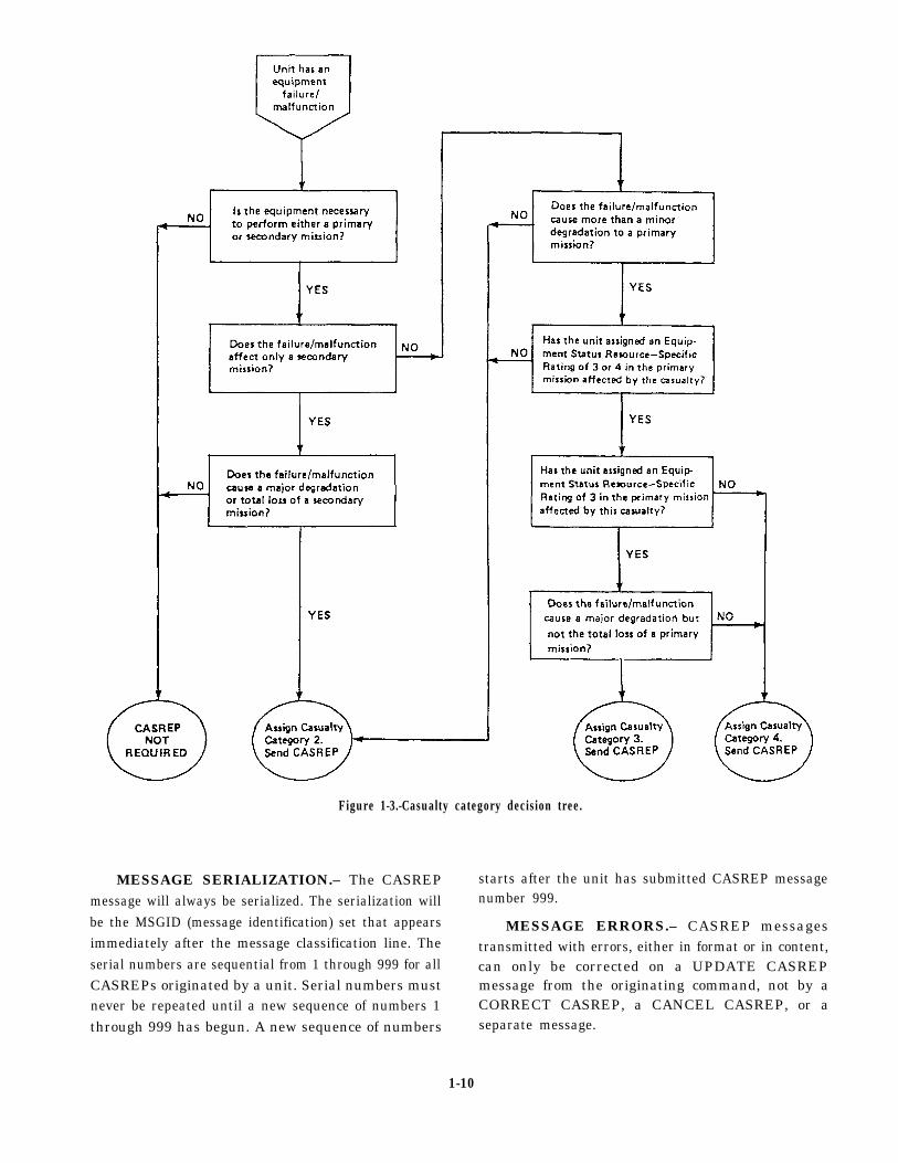
Figure 1-3.-Casualty category decision tree.
MESSAGE SERIALIZATION.– The CASREPmessage will always be serialized. The serialization willbe the MSGID (message identification) set that appearsimmediately after the message classification line. Theserial numbers are sequential from 1 through 999 for allCASREPs originated by a unit. Serial numbers mustnever be repeated until a new sequence of numbers 1through 999 has begun. A new sequence of numbers
starts after the unit has submitted CASREP messagenumber 999.
MESSAGE ERRORS.– CASREP messagestransmitted with errors, either in format or in content,can only be corrected on a UPDATE CASREPmessage from the originating command, not by aCORRECT CASREP, a CANCEL CASREP, or aseparate message.
1-10
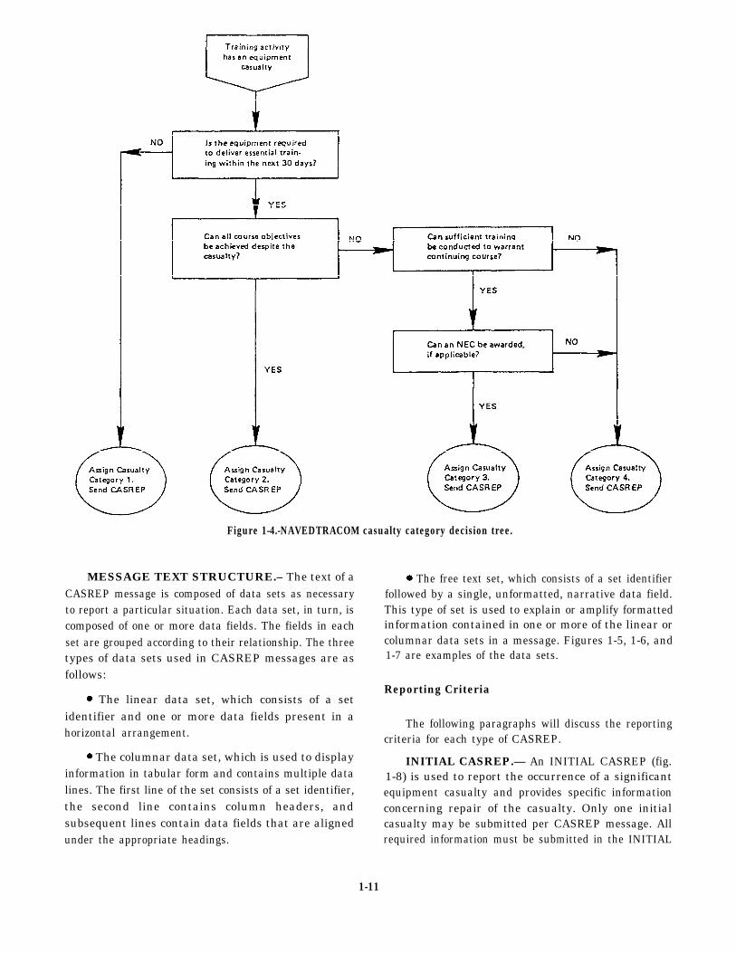
Figure 1-4.-NAVEDTRACOM casualty category decision tree.
MESSAGE TEXT STRUCTURE.– The text of aCASREP message is composed of data sets as necessaryto report a particular situation. Each data set, in turn, iscomposed of one or more data fields. The fields in eachset are grouped according to their relationship. The threetypes of data sets used in CASREP messages are asfollows:
The linear data set, which consists of a setidentifier and one or more data fields present in ahorizontal arrangement.
The columnar data set, which is used to displayinformation in tabular form and contains multiple datalines. The first line of the set consists of a set identifier,the second line contains column headers, andsubsequent lines contain data fields that are alignedunder the appropriate headings.
The free text set, which consists of a set identifierfollowed by a single, unformatted, narrative data field.This type of set is used to explain or amplify formattedinformation contained in one or more of the linear orcolumnar data sets in a message. Figures 1-5, 1-6, and1-7 are examples of the data sets.
Reporting Criteria
The following paragraphs will discuss the reportingcriteria for each type of CASREP.
INITIAL CASREP.— An INITIAL CASREP (fig.1-8) is used to report the occurrence of a significantequipment casualty and provides specific informationconcerning repair of the casualty. Only one initialcasualty may be submitted per CASREP message. Allrequired information must be submitted in the INITIAL
1-11
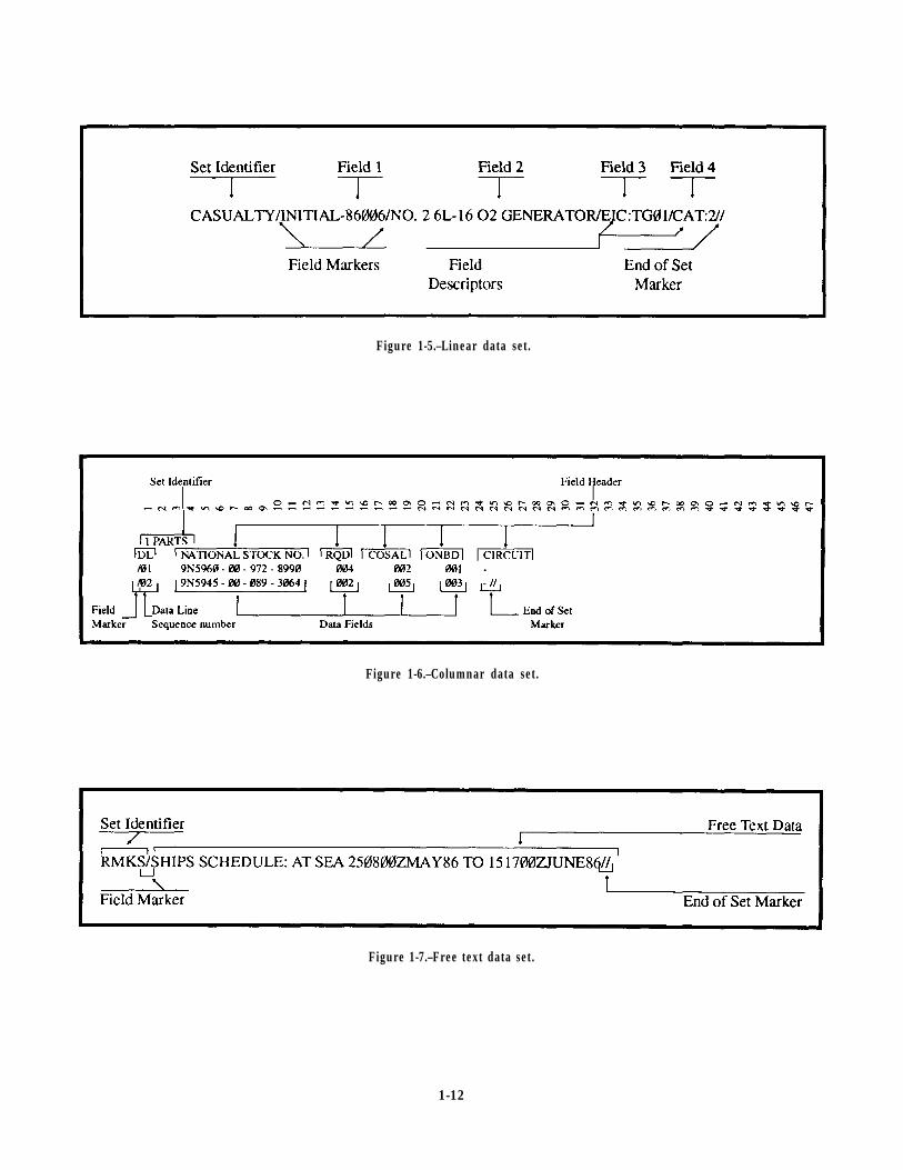
Figure 1-5.–Linear data set.
Figure 1-6.–Columnar data set.
Figure 1-7.–Free text data set.
1-12
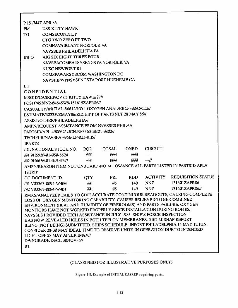
Figure 1-8.-Example of INITIAL CASREP requiring parts.
1-13
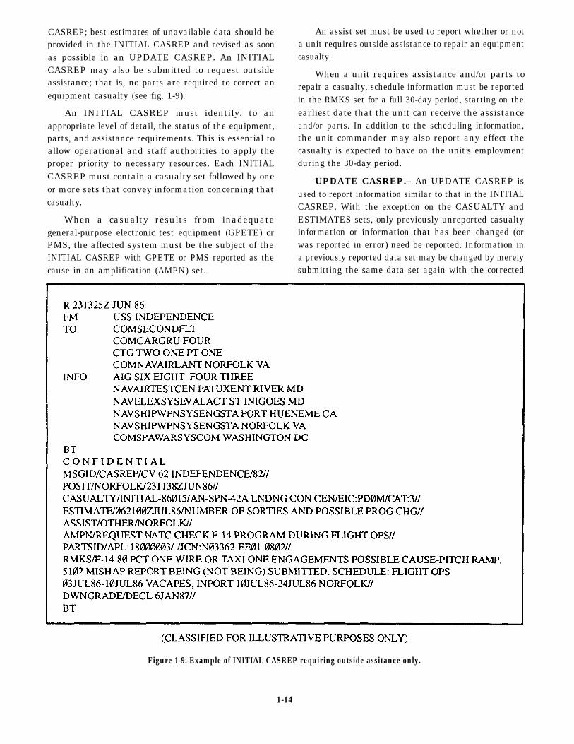
CASREP; best estimates of unavailable data should beprovided in the INITIAL CASREP and revised as soonas possible in an UPDATE CASREP. An INITIALCASREP may also be submitted to request outsideassistance; that is, no parts are required to correct anequipment casualty (see fig. 1-9).
An INITIAL CASREP must identify, to anappropriate level of detail, the status of the equipment,parts, and assistance requirements. This is essential toallow operational and staff authorities to apply theproper priority to necessary resources. Each INITIALCASREP must contain a casualty set followed by oneor more sets that convey information concerning thatcasualty.
When a casualty results from inadequategeneral-purpose electronic test equipment (GPETE) orPMS, the affected system must be the subject of theINITIAL CASREP with GPETE or PMS reported as thecause in an amplification (AMPN) set.
An assist set must be used to report whether or nota unit requires outside assistance to repair an equipmentcasualty.
When a unit requires assistance and/or parts torepair a casualty, schedule information must be reportedin the RMKS set for a full 30-day period, starting on theearliest date that the unit can receive the assistanceand/or parts. In addition to the scheduling information,the unit commander may also report any effect thecasualty is expected to have on the unit’s employmentduring the 30-day period.
UPDATE CASREP.– An UPDATE CASREP isused to report information similar to that in the INITIALCASREP. With the exception on the CASUALTY andESTIMATES sets, only previously unreported casualtyinformation or information that has been changed (orwas reported in error) need be reported. Information ina previously reported data set may be changed by merelysubmitting the same data set again with the corrected
Figure 1-9.-Example of INITIAL CASREP requiring outside assitance only.
1-14

information, except for ASSIST, 1PARTS, and 1STRIPsets. A unit must submit an UPDATE CASREP for acasualty when the following occurs:
There is a need to complete information reportingrequirements or to revise previously submittedinformation.
The casualty situation changes; for example, the
Additional malfunctions are discovered in thesame item of equipment.
All parts ordered to repair the equipment arereceived.
Upon receipt of any significant part orequipment, inclusion of the date of receipt isrequired.
estimated repair date has changed, parts status Only one casualty may be updated per UPDATEhas changed significantly, additional assistance CASREP message. Figure 1-10 is an example of anis needed, and so forth. UPDATE CASREP message.
Figure 1-10.-Example of an UPDATE CASREP message.
1-15
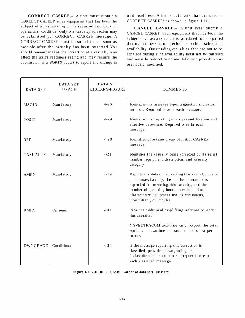
CORRECT CASREP.– A unit must submit a unit readiness. A list of data sets that are used inCORRECT CASREP when equipment that has been the CORRECT CASREPs is shown in figure 1-11.subject of a casualty report is repaired and back in CANCEL CASREP.– A unit must submit aoperational condition. Only one casualty correction maybe submitted per CORRECT CASREP message. A
CANCEL CASREP when equipment that has been the
CORRECT CASREP must be submitted as soon assubject of a casualty report is scheduled to be repairedduring an overhaul period or other scheduled
possible after the casualty has been corrected Youshould remember that the correction of a casualty may
availability. Outstanding casualties that are not to be
affect the unit’s readiness rating and may require therepaired during such availability must not be canceled
submission of a SORTS report to report the change inand must be subject to normal follow-up procedures aspreviously specified.
DATA SET DATA SETDATA SET USAGE LIBRARY-FIGURE COMMENTS
MSGID Mandatory 4-26 Identities the message type, originator, and serialnumber. Required once in each message.
POSIT Mandatory 4-29 Identities the reporting unit’s present location andeffective date-time. Required once in eachmessage.
REF Mandatory 4-30 Identifies date-time group of initial CASREPmessage.
CASUALTY Mandatory 4-21 Identifies the casualty being corrected by its serialnumber, equipment description, and casualtycategory
AMPN Mandatory 4-19 Reports the delay in correcting this casualty due toparts unavailability, the number of manhoursexpended in correcting this casualty, and thenumber of operating hours since last failure.Characterize equipment use as continuous,intermittent, or impulse.
RMKS Optional 4-31 Provides additional amplifying information aboutthis casualty.
NAVEDTRACOM activities only: Report the totalequipment downtime and student hours lost percourse.
DWNGRADE Conditional 4-24 If the message reporting this correction isclassified, provides downgrading ordeclassification instructions. Required once ineach classified message.
Figure 1-11.-CORRECT CASREP–order of data sets summary.
1-16
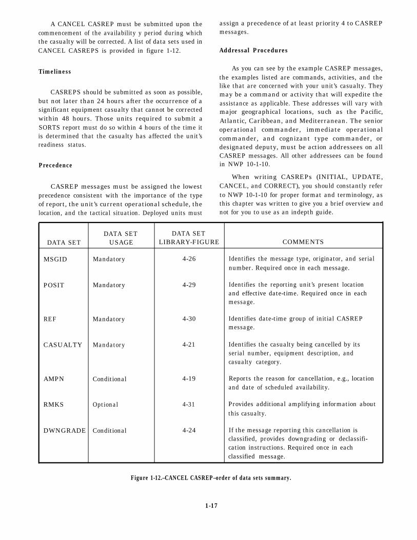
A CANCEL CASREP must be submitted upon thecommencement of the availability y period during whichthe casualty will be corrected. A list of data sets used inCANCEL CASREPS is provided in figure 1-12.
Timeliness
CASREPS should be submitted as soon as possible,but not later than 24 hours after the occurrence of asignificant equipment casualty that cannot be correctedwithin 48 hours. Those units required to submit aSORTS report must do so within 4 hours of the time itis determined that the casualty has affected the unit’sreadiness status.
Precedence
CASREP messages must be assigned the lowestprecedence consistent with the importance of the typeof report, the unit’s current operational schedule, the
assign a precedence of at least priority 4 to CASREPmessages.
Addressal Procedures
As you can see by the example CASREP messages,the examples listed are commands, activities, and thelike that are concerned with your unit’s casualty. Theymay be a command or activity that will expedite theassistance as applicable. These addresses will vary withmajor geographical locations, such as the Pacific,Atlantic, Caribbean, and Mediterranean. The senioroperational commander, immediate operationalcommander, and cognizant type commander, ordesignated deputy, must be action addressees on allCASREP messages. All other addressees can be foundin NWP 10-1-10.
When writing CASREPs (INITIAL, UPDATE,CANCEL, and CORRECT), you should constantly referto NWP 10-1-10 for proper format and terminology, asthis chapter was written to give you a brief overview and
location, and the tactical situation. Deployed units must not for you to use as an indepth guide.
DATA SET DATA SETDATA SET USAGE LIBRARY-FIGURE COMMENTS
MSGID Mandatory 4-26 Identifies the message type, originator, and serialnumber. Required once in each message.
POSIT Mandatory 4-29 Identifies the reporting unit’s present locationand effective date-time. Required once in eachmessage.
REF Mandatory 4-30 Identifies date-time group of initial CASREPmessage.
CASUALTY Mandatory 4-21 Identifies the casualty being cancelled by itsserial number, equipment description, andcasualty category.
AMPN Conditional 4-19 Reports the reason for cancellation, e.g., locationand date of scheduled availability.
RMKS Optional 4-31 Provides additional amplifying information aboutthis casualty.
DWNGRADE Conditional 4-24 If the message reporting this cancellation isclassified, provides downgrading or declassifi-cation instructions. Required once in eachclassified message.
Figure 1-12.–CANCEL CASREP–order of data sets summary.
1-17
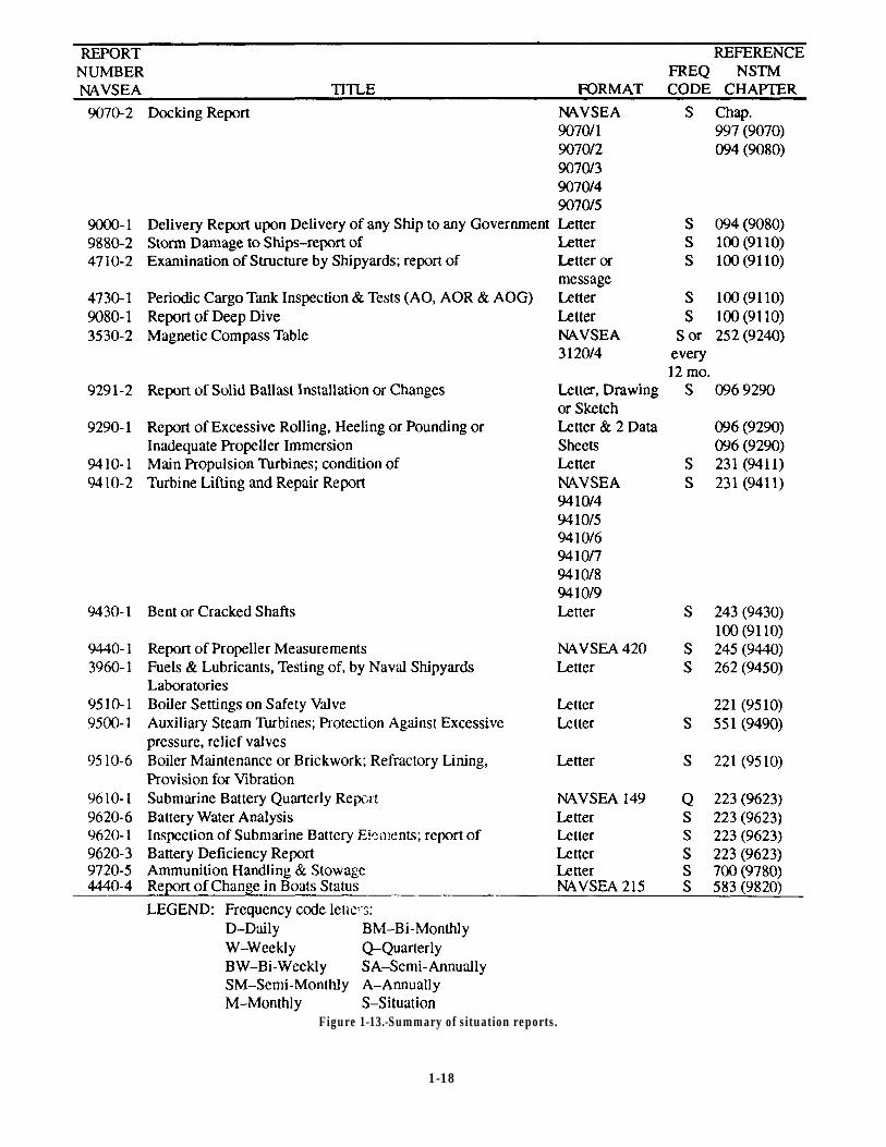
Figure 1-13.-Summary of situation reports.
1-18

SITUATION REPORTS summary of one-time reports pertaining to theengineering department. The situation that occasions the
Situation reports (SITREPs) are one-time reports reports listed in the summary are explained in therequired when certain situations arise. Figure 1-13 is a references listed.
1-19

1.
2.
3.
4.
5.
6.
7.
CHAPTER 2
QUALITY ASSURANCE
LEARNING OBJECTIVES
Upon completion of this chapter, you will be able to do the following:
Describe the purpose and goal of the QualityAssurance (QA) program.
Identify the chain of command for a QA programand the responsibilities of personnel in the chain ofcommand.
Describe QA personnel qualification requirements.
Describe the operation of a QA program.
Identify the definitions of terms used in QA.
Describe the levels of essentiality.
Identify the purpose of tests and inspectionsassociated with the QA program.
8.
9.
10.
11.
12.
Describe the responsibilities of personnel
conducting tests and inspections.
Discuss the requirements and procedures in
conducting a QA program inspection.
Recognize the contents and format of various QA
forms and reports.
Identify the steps in preparing various QA forms and
reports.
Recognize the contents and format of other forms
that are to be submitted in conjunction with QA
forms and reports.
INTRODUCTION
As you progress towards IC1 or ICC, yourresponsibilities become more involved in qualityassurance (QA). You will be responsible for ensuringthat the work performed by your technicians and byoutside help is completed with the highest qualitypossible. Most of the personnel in the IC rating takepride in the performance of their jobs and they normallystrive for excellence.
As the work group or work center supervisor, oneof your many responsibilities will be to ensure that allcorrective action performed is done correctly and meetsprescribed standards. Improper performance of repairsor installations could endanger the lives of personnel oran expensive piece of equipment or cause another pieceof equipment to fail prematurely. A well-organized QAand inspection program will minimize the impact of amoment of carelessness or inattention. This chapter willfamiliarize you with the purpose, basic organization,and mechanics of the QA program.
You may be assigned as a QA representative orcollateral duty inspector from time to time. As a workcenter supervisor, you will be responsible for the quality
control (QC) program in your workspaces. It isimportant that you become quality conscious. To makeany program successful, you will have to know andunderstand the QA program and obtain the cooperationand participation of all your personnel. This requires youto ensure that all tests and repairs conform to theirprescribed standards. In addition, you as a supervisormust train all your personnel in QC.
QUALITY ASSURANCE PROGRAM
The QA program was established to providepersonnel with information and guidance necessary toadminister a uniform policy of maintenance and repairof ships and submarines. The QA program is intendedto impart discipline into the repair of equipment, safetyof personnel, and configuration control, therebyenhancing ship’s readiness.
The various QA manuals set forth minimum QArequirements for both the surface fleet and thesubmarine force. If more stringent requirements areimposed by higher authority, such requirements takeprecedence. If conflicts exist between the QA manualand previously issued letters and transmittals by the
2-1
appropriate force commanders, the QA manual takesprecedence. Such conflicts should be reported to theappropriate officials.
The instructions contained in the QA manual applyto every ship and activity of the force. Although therequirements are primarily applicable to the repair andmaintenance done by the force intermediatemaintenance activities (IMAs), they also apply tomaintenance done aboard ship by ship’s force. In allcases, when specifications cannot be met, a departurefrom specifications request must be completed andreported.
Because of the wide range of ship types andequipment and the varied resources available formaintenance and repair, the instructions set forth in theQA manual are general in nature. Each activity mustimplement a QA program to meet the intent of the QAmanual. The goal should be to have all repairs conformto QA specifications.
PROGRAM COMPONENTS
The basic thrust of the QA program is to ensure thatyou comply with technical specifications during allwork on ships of both the surface fleet and the submarineforce. The key elements of the program are as follows:
Administrative. This includes training andqualifying personnel, monitoring and auditingprograms, and completing the QA forms andrecords.
Job Execution. This includes preparing workprocedures, meeting controlled materialrequirements, requisitioning material,conducting in-process control of fabrication andrepairs, testing and recertifying, anddocumenting any departure from specifications.
CONCEPTS OF QUALITY ASSURANCE
The ever-increasing technical complexity ofpresent-day surface ships and submarines has spawnedthe need for special administrative and technicalprocedures known collectively as the QA program. TheQA concept is fundamentally the prevention of defects.This encompasses all events from the start ofmaintenance operations until their completion. It is theresponsibility of all maintenance personnel.Achievement of QA depends on prevention ofmaintenance problems through your knowledge andspecial skills. As a supervisor, you must consider QArequirements whenever you plan maintenance. The
fundamental rule for you to follow for all maintenanceis that TECHNICAL SPECIFICATIONS MUST BEMET AT ALL TIMES.
Prevention is concerned with regulating eventsrather than being regulated by them. It relies oneliminating maintenance failures before they happen.This extends to safety of personnel, maintenance ofequipment, and virtually every aspect of the totalmaintenance effort.
Knowledge is obtained from factual information.This knowledge is acquired through the proper use ofdata collection and analysis programs. The maintenancedata collection system provides maintenance managersunlimited quantities of factual information. Theexperienced maintenance manager providesmanagement with a pool of knowledge. Correct use ofthis knowledge provides the chain of command with thetools necessary to achieve maximum shipboardreadiness.
Special skills, normally not possessed byproduction personnel, are provided by a staff of trainedpersonnel for analyzing data and supervising QAprograms.
The QA program provides an efficient method forgathering and maintaining information on the qualitycharacteristics of products and on the source and natureof defects and their impact on current operations. Itpermits decisions to be based on facts rather thanintuition or memory. It provides comparative data thatwill be useful long after details of particular times orevents have been forgotten. QA requires both authorityand assumption of responsibility for action.
A properly functioning QA program points outproblem areas to maintenance managers so they can takeappropriate action to accomplish the following:
Improve the quality, uniformity, and reliability ofthe total maintenance effort.
Improve the work environment, tools, andequipment used in the performance ofmaintenance.
Eliminate unnecessary man-hour and dollarexpenses.
Improve the training, work habits, andprocedures of maintenance personnel.
Increase the excellence and value of reports andcorrespondence originated by the maintenanceactivity.
2-2
– Distribute required technical information moreeffectively.
– Establish realistic material and equipmentrequirements in support of the maintenanceeffort.
To obtain full benefits from a QA program,teamwork must be achieved first. Blend QA functionsin with the interest of the total organization and youproduce a more effective program. Allow each workerand supervisor to use an optimum degree of judgmentin the course of the assigned daily work; a person’sjudgment plays an important part in the quality of thework. QA techniques supply each person with theinformation on actual quality. This information providesa challenge to the person to improve the quality of thework. The resulting knowledge encourages the bestefforts of all your maintenance personnel.
QA is designed to serve both management andproduction equally. Management is served when QAmonitors the complete maintenance effort of thedepartment, furnishes factual feedback of discrepanciesand deficiencies, and provides the action necessary toimprove the quality, reliability, and safety ofmaintenance. Production is served by having the benefitof collateral duty inspectors formally trained ininspection procedures; it is also served in receivingtechnical assistance in resolving production problems.Production personnel are not relieved of their basicresponsibility for quality work when you introduce QAto the maintenance function. Instead, you increase theirresponsibility by adding accountability. Thisaccountability is the essence of QA.
GOALS
The goals of the QA program are to protectpersonnel from hazardous conditions, increase the timebetween equipment failure, and ensure proper repair offailed equipment. The goals of the QA program areintended to improve equipment reliability, safety ofpersonnel, and configuration control. Achievement ofthese goals will ultimately enhance the readiness of shipand shore installations. There is a wide range of shiptypes and classes in the fleet, and there are equipmentdifferences within ship classes. This complicatesmaintenance support and increases the need for aformalized program that will provide a high degree ofconfidence that overhaul, installations, repairs, andmaterial will consistently meet conformance standards.
THE QUALITY ASSURANCE LINK TOMAINTENANCE
Accomplishment of repairs and alterationsaccording to technical specifications has been along-standing requirement for U.S. Navy ships.Ultimate responsibility to ensure that this requirementis met rests with the person performing the maintenance.To do the job properly, a worker must be
properly trained,
provided with correct tools and parts,
familiar with the applicable technical manualsand plans, and,
adequately supervised.
These elements continue to be the primary means ofassuring that maintenance is performed correctly. As asupervisor, you can readily see where you fit in.
Once the need for maintenance is identified, youmust consider QA requirements concurrent y with theplanning and performing of that maintenance. Technicalspecifications will come from a variety of sources. Thedetermination of which sources are applicable to theparticular job will be the most difficult part of yourplanning effort. Once you make that determination, themaintenance objective becomes two-fold:
1. Ensure the maintenance effort meets allspecifications.
2. Ensure the documentation is complete, accurate,and auditable.
It is vital that you approach maintenance planningfrom the standpoint of first-time quality.
THE QUALITY ASSURANCEORGANIZATION
The QA program for naval forces is organized intodifferent levels of responsibility. For example, the QAprogram for the Naval Surface Force for the PacificFleet is organized into the following levels ofresponsibility: type commander, readiness supportgroup/area maintenance coordinator, and the IMAs. TheQA program for the submarine force is organized intofour levels of responsibility: type commander, groupand squadron commanders, IMA commanding officers,and ship commanding officer/officers in charge. The QAprogram for the Naval Surface Force for the AtlanticFleet is organized into five levels of responsibility: force
2-3
commander, audits, squadron commanders, IMAs, andforce ships.
The QA program organization (Navy) begins withthe commanders in chief of the fleets, who provide thebasic QA program organization responsibilities andguidelines.
The type commanders (TYCOMs) provideinstruction, policy, and overall direction forimplementation and operation of the force QA program.TYCOMs have a force QA officer assigned toadminister the force QA program.
The commanding officers (COs) are responsible tothe force commander for QA in the maintenance and
Conducting QA audits as required by the QAmanual and following upon corrective actions toensure compliance with the QA program
Maintaining liaison with the IMA office for allwork requiring QA controls
Providing QA guidance to the supply departmentwhen required
Preparing QA/QC reports (as required) by higherauthority
Maintaining liaison with the ship engineer in allmatters pertaining to QA to ensure compliancewith the QA manual
repair of the ships. The CO is responsible for organizing The ship quality control inspectors (SQCIs),and implementing a QA program within the ship to carry usually the work center supervisor and two others from
out the provisions of the TYCOMs QA manual. the work center, must have a thorough understanding of
The CO ensures that all repair actions performed bythe QA program. Some of the other responsibilities anSQCI
ship’s force conform to provisions of the Qa manual aswell as pertinent technical requirements.
The CO ensures that all work requests requiring
special controls are properly identified and thatapplicable supporting documentation is provided to themaintenance or repair activity using the applicable QAform.
The CO also ensures that departures fromspecifications are reported, required audits areconducted, and adequate maintenance is performed forthe material condition necessary to support continuedunrestricted operations.
The quality assurance officer (QAO) isresponsible to the CO for the organization,administration, and execution of the ship’s QA programaccording to the QA manual. On most surface shipsother than IMAs, the QAO is the chief engineer, with asenior chief petty officer assigned as the QA coordinate.The QAO is responsible for the following:
– Coordinating the ship’s QA training program
– Maintaining ship’s QA records and inspectionreports according to the QA manual
– Maintaining auditable departure fromspecification records
will have are as follows:
Maintain ship records to support the QAprogram.
Inspect all work for conformance tospecifications.
Ensure that only calibrated equipment is used inacceptance testing and inspection of work
Witness and document all tests.
Ensure that all materials or test results that fail tomeet specifications are recorded and reported.
Train personnel in QC.
Initiate departure from specification reports(discussed later) when required.
Ensure that all inspections beyond thecapabilities of the ship’s QA inspector areperformed and accepted by IMA before finalacceptance and installation of the product by theship.
Report all deficiencies and discrepancies to theship’s QA coordinator (keeping the divisionofficer informed).
Develop controlled work packages for all shiprepair work requiring QA controls.
– Reviewing procedures and controlled work More on SQCI duties will be discussed later in thispackages prepared by the ship before submission chapter, because this will more than likely be the areato the engineer you will be associated with.
2-4
RESPONSIBILITIES FOR QUALITY OF following the completion of a task or series ofMAINTENANCE tasks. QA inspection of work areas following
Although the CO is responsible for the inspectionand quality of material within a command, he or shedepends on the full cooperation of all hands to meet thisresponsibility. The responsibility for establishing asuccessful program to attain high standards of qualityworkmanship cannot be discharged by merely creatinga QA division within a maintenance organization. Tooperate effectively, this division requires the full supportof everyone within the organization. It is not theinstruments, instructions, and other facilities for makinginspections that determine the success or failure inachieving high standards of quality, it is the frame ofmind of all personnel.
task completion by several different personnel isan example of a final inspection.
You have the direct responsibility as productionsupervisor to assign a collateral duty inspector at thetime you assign work. This allows your inspector tomake the progressive inspection(s) required; theinspector is not then confronted with a job alreadycompleted, functionally tested, and buttoned up.Remember, production personnel to which you haveassigned the dual role of inspector cannot inspect orcertify their own work.
SHIP QUALITY CONTROL INSPECTOR
Quality maintenance is vital to the effectiveoperation of any maintenance organization. To achieve The SQCI is the frontline guardian of adherence tothis high quality of world each of your personnel must quality standards. In the shops and on the deck plates,know not only a set of specification limits, but also the the SQCIs must constantly remind themselves that theypurpose for these limits. can make a difference in the quality of a product. They
The person with the most direct concern for qualityworkmanship is you–the production supervisor. Thisstems from your responsibility for the professionalperformance of your assigned personnel. You mustestablish procedures within the work center to ensurethat all QA inspection requirements are complied withduring all maintenance evolutions. In developingprocedures for your work center, keep in mind thatinspections normally fall into one of the three followinginspection areas:
RECEIVING OR SCREENING INSPEC-TIONS. These inspections apply to material,components, parts, equipment, logs, records, anddocuments. These inspections determine thecondition of material, proper identification,maintenance requirements, disposition, andcorrectness of accompanying records anddocuments.
IN-PROCESSING INSPECTIONS. Theseinspections are specific QA actions that arerequired during maintenance or actions in caseswhere satisfactory task performance cannot bedetermined after maintenance has beencompleted. These inspections includewitnessing, application of torque, functionaltesting, adjusting, assembling, servicing, andinstallation.
FINAL INSPECTION. These inspectionscomprise specific QA actions performed
must be able to see and be recognized for theircontributions in obtaining quality results.
As a work center supervisor, you will be responsiblefor the QA program in your work spaces. You mustrealize that QA inspections are essential elements of aneffective QA program. You are responsible to yourdivision officer and the QAO for coordinating andadministering the QA program within your work center,You are responsible for ensuring that all repaired unitsare ready for issue. This doesn’t mean you have toinspect each item repaired in your shop personally; youshould have two reliable, well-trained technicians toassist you in QA inspections. To avoid the manyproblems caused by poor maintenance repair practicesor by the replacement of material with faulty or incorrectmaterial, you must take your position as an SQCI veryseriously. When you inspect a certain step of installation,ensure to the utmost of your knowledge and ability thatthe performance and product meet specifications andthat installations are correct.
Most commands that have a QA program will issueyou a special card that will identify you as a qualifiedSQCI for your command. Each of your shop SQCIs alsowill be assigned a personal serial number by the QAOas proof of certification to use on all forms and tags thatrequire initials as proof that certified tests andinspections were completed. This will providedocumented proof and traceability that each item or lotof items meets the material and workmanship for thatstage of workmanship. Also, you will be given a QCIstamp so that you can stamp the QCI certification on the
2-5
forms or tags as a checkoff of a particular progressivestep of inspection or final job completion. The stampwill also serve as proof of inspection and acceptance ofeach satisfactory shop end product. This stamp mayhave your command identification and a QCI numberthat is assigned and traceable to you.
As an SQCI, you should be thoroughly familiar withall aspects of the QA program and the QC proceduresand requirements of your specialty.
You will be trained and qualified by the QAOaccording to the requirements set forth by yourapplicable QA manual and the QC requirementsapplicable to your installation. The QAO will interviewyou to determine your general knowledge of records,report completion, and filing requirements.
You will report to the appropriate QA supervisorswhile keeping your division officer informed of matterspertaining to QA work done in the shop. You and yourwork center QCIs will be responsible for the following:
Developing a thorough understanding of the QAprogram.
Ensuring that all shop work performed by yourwork center personnel meets the minimumrequirements set forth in the latest plans,directives, and specifications of higher authorityand that controlled work packages (CWPs) areproperly used on repair work.
Ensuring that all work center personnel arefamiliar with applicable QA manuals byconducting work center/division training.
Maintaining records and files to support the QAprogram, following the QA manual.
Assuring that your work center and, whenapplicable, division personnel do not usemeasuring devices, instruments, inspection tools,gauges, or fixtures for production acceptance andtesting that do not have current calibrationstickers or records attached or available.
Performing quality control inspections of eachproduct manufacturcd or repaired by your workcenter.
Assisting your division officer and QAO inconducting internal audits as required and takingcorrective action on noted discrepancies.
Alternate SQCIs are usually assigned as backups tothe regular SQCIs. Their qualifications and
responsibilities will be the same as those of the regularlyassigned SQCI.
WORK CENTER CONTROLLEDMATERIAL PETTY OFFICERS
As a supervisor, you must also ensure thatprocedures governing controlled material are followed.You can do this by having one or more of your workcenter personnel trained in the procedures forinspecting, segregating, stowing, and issuing controlledmaterial. When they have completed their training,designate them as controlled material petty officers(CMPOs).
SHOP CRAFTSMAN
As stated earlier, the person doing the work, whetherit be manufacturing or repairing, is responsible to youwhen questions arise about the work being performed,whether the work is incorrect, incomplete, or unclear.Make sure your workers know to stop and seek workinstructions or clarification from you when questions orconditions arise which may present an impediment tothe successful completion of the task at hand.
A good lesson to teach over and over to all workersis to strive to achieve first-time quality on every taskassigned. This not only will instill pride andprofessionalism in their work, but also will ensure aquality product.
QUALITY ASSURANCEREQUIREMENTS, TRAINING, AND
QUALIFICATION
A comprehensive personnel training program is thenext step in an effective QA program. For inspectors tomake a difference, they must be both trained andcertified. They must have formal or informal training ininspection methods, maintenance and repair, andcertification of QA requirements. Costly mistakes, madeeither from a lack of knowledge or improper training,can be entirely eliminated with a good QA trainingprogram at all levels of shop or work group organization.Before personnel can assume the responsibility ofcoordinating, administering, and executing the QAprogram, they must meet certain requirements.Personnel assigned to the QA division or QC personnelyou have assigned in your work center, such as SQCIs,CMPOs, or their alternates, should be highly motivatedtowards the QA program. It is imperative that aqualification and requalification program be establishedfor those personnel participating in the program. Where
2-6
military standards and NAVSEA technical documentsrequire formal technical training or equivalent, thoserequirements must be met and personnel qualificationvigorously and effectively monitored to ensure thatqualifications are updated and maintained. When formaltraining for a specific skill is not a requirement, theguidelines of the QA manual may be used as a basis fortraining to ensure that personnel are provided with thenecessary expertise to perform a required skill.Personnel who obtain a QA qualification must undergoperiodic QA training and examinations, both oral andwritten, to maintain the qualification. We will discussthis procedure in the following paragraphs.
QUALITY ASSURANCE OFFICER
The QAO’s primary duty, assigned by the CO inwriting, is to oversee the QA program. The QAO ensuresthat personnel assigned to perform QA functions receivecontinuous training in inspecting, testing, and QCmethods specifically applicable to their area ofassignment. The QAO also ensures that SQCIs receivecross training to perform QA functions not in theirassigned area. This training includes local trainingcourses, on-the-job training (OJT), rotation ofassignments, personnel qualification standards (PQS),and formal schools.
Whenever possible, the QAO receives formaltraining according to the QA manual. He or she isresponsible to the repair officer for planning andexecuting a QA training program for the variousqualifications required for QA. The QAO personallyinterviews each perspective SQCI to ensure that theperson has a thorough understanding of the QA mission.
REPAIR OFFICER
The repair officer (RO) maintains qualifiedpersonnel in all required ratings for the QA program inhis or her department. He or she also ensures thatpersonnel assigned to the repair department areindoctrinated and trained in QA practices andrequirements.
DIVISION OFFICERS
Division officers ensure that their divisionalpersonnel receive training and are qualified in the QAprocess and maintain those qualifications. They makesure that all repairs, inspections, and production workrequiring a witness are witnessed by division workcenter QC inspectors and that all test records arccompleted and signed. Division officers ensure that all
test personnel observe all safety precautions pertainingto the specific equipment and wear personal safetyequipment at all times while conducting theseevolutions. They also make sure that test equipment, ifrequired, is properly calibrated and that adequateoverpressure protection is provided duringdivision spaces.
tests in
QUALITY ASSURANCE SUPERVISORS
QA supervisors are senior petty officers who havebeen properly qualified according to the QA manual.They have a thorough understanding of the QA functionand are indoctrinated in all aspects of the coordinating,administering, and auditing processes of the QAprogram. QA supervisors train all SQCIs and CMPOsand ensure their recertification upon expiration ofqualifications. QA supervisors also administer writtenexaminations to all perspective SQCIs and those SQCIswho require recertification to ensure a thoroughunderstanding of the QA program.
SHIP QUALITY CONTROL INSPECTORS
SQCIs are trained by the QA supervisors inapplicable matters pertaining to the QA program. Aninspector must be equally as skilled as the craftsmanwhose work he or she is required to inspect. Not onlyshould the inspector know the fabrication or repairoperation and what workers are required to do, but alsohow to go about doing it.
To recognize a product quality characteristic,SQCIs must be given certain tools and training. Tools oftheir trade should include measuring devices anddocumentation. Their training is both formal(documented course of instruction) and informal (OJT).They must pass a written test given by the QAsupervisor, as well as an oral examination given by theQAO. The written exam includes general requirementsof the QA program and specific requirements relative totheir particular specialty. Successful completion of theshop qualification program course for QCIs will fulfillthis requirement. The QA supervisor may alsoadminister a practical examination to perspective SQCIsin which they will have to demonstrate knowledge ofrecords and report completion, and tiling requirements.This will ensure that the SQCIs have a generalknowledge of and proper attitude toward the QAprogram.
2-7
CONTROLLED MATERIAL PETTYOFFICERS
CMPOs are normally petty officers, E-4 or E-5, whoare thoroughly familiar with controlled materialrequirements as outlined in the QA manual. They, too,are trained and qualified by a QA supervisor. The QAOwill interview them, as he or she did for the SQCIs, tosee if they have a general knowledge of controlledmaterial requirements.
The QA supervisor will give them a written test toensure that they have sufficient knowledge of controlledmaterial requirements and procedures to carry out theirresponsibilities effectively.
OPERATION OF A QUALITYASSURANCE PROGRAM
Initiating an effective, ongoing QA program is anall-hands effort. It takes the cooperation of all shoppersonnel to make the program work. As the shop orwork group supervisor, you will be responsible forgetting the program rolling.
The key elements are a good personnel orientationprogram, a comprehensive personnel training program,use of the proper repair procedures, and uniforminspection procedures. When you have organized theshop or work center and have placed all these elementsin practice, your QA program will be underway. Theseelements are discussed in the following paragraphs.
PERSONNEL ORIENTATION
The best way to get the support of your personnel isto show them how an effective QA program will benefitthem personally. Eliminating or reducing prematurefailures in repaired units and introducing high-reliabilityrepairs will appreciable y reduce their workload, savingthem frustration and enhancing the shop or work groupreputation. This program, as any new program or changeto an existing program, will probably meet withopposition from some shop personnel. By showing yourshop personnel the benefits of a QA program, yougreatly reduce opposition to the change.
REPAIR PROCEDURES
Repair procedures may be defined as all of theaction required to return an equipment to its properoperating condition after a defect has been discovered.Repair procedures include parts handling, disassembly,component removal or replacement, and reassembly,
Strictly adhering to the proper repair procedures willalmost entirely eliminate premature failures. You, asshop supervisor or work group supervisor, andsubordinate work center supervisors are responsible forensuring that the proper procedures are used in handlingall repairable units.
QUALITY ASSURANCE TERMS ANDDEFINITIONS
As a supervisor, you need to be able to talk to yourpersonnel about QA and have them be able to carry outyour instructions properly and promptly. You need topromote the use of words and phrases pertaining toquality and related programs, thus improving the clarityin your communication with them about QA. To do this,you need to understand the terms frequently usedthroughout the QA program. Each TYCOM’s QAmanual and MIL-STD-109 has a complete list of theseterms, but the most frequently used terms are listed here:
QUALITY ASSURANCE. Quality assurance (QA)is a system that ensures that materials, data,supplies, and services conform to technicalrequirements and that repaired equipment performssatisfactory.
QUALITY CONTROL. Quality control (QC) is amanagement function that attempts to eliminatedefective products, whether they are produced orprocured.
ACCEPTANCE. Acceptance is when an authorizedrepresentative approves specific services rendered(such as a repair or manufactured part).
CALIBRATION. This is the comparison of twoinstruments or measuring devices, one of which isa standard of known accuracy traceable to nationalstandards, to detect, correlate, report, or eliminateby adjustment any discrepancy in accuracy of theinstrument or measuring device being comparedwith the standard.
INSPECTION. This is the examination and testingof components and services to determine whetherthey conform to specified requirements.
IN-PROCESS INSPECTION. This type ofinspection is performed during the manufacture andrepair cycle to prevent production defects. It is also
perfomed to identify production problems ormaterial defects that are not detectable when the jobis complete.
INSPECTION RECORD. Inspection recordscontain data resulting from inspection actions.
2-8
SPECIFICATIONS. A specification is any technical maintenance action, a test, or an inspection is doneor administrative directive, such as an instruction, a using specific guidelines, tools, and equipment.
technical manual, a drawing, a plan, or publication, RELIABILITY. Reliability means the probabilitythat defines repair criteria. that an item will perform its intended function for a
AUDIT. An audit, as it applies to the QA program, specified interval under stated conditions.
is a periodic or special evaluation of details, plans, SUBSAFE. The acronym SUBSAFE is a shortpolicies, procedures, products, directives, and reference to the Submarine Safety Program, whichrecords necessary to determine compliance with provides a high level of confidence in the materialexisting requirements. conditions of the hull integrity boundary.
CERTIFIED (LEVEL 1) MATERIAL. This is SUBSAFE will be discussed later in this chapter.
material that has been certified (as to its material andphysical properties as well as traceability to themanufacturer) by a qualified certification activity. THE CONTROLLED WORK PACKAGE
This material has a material and identificationcontrol (MIC) number assigned along with acertification document.
CONTROLLED MATERIAL. This is any materialthat must be accounted for and identified throughoutthe manufacturing or repair process. (See level ofessentiality.)
CONTROLLED WORK PACKAGE. A controlledwork package (CWP) is an assemblage ofdocuments identified by a unique serial number thatmay contain detailed work procedures, purchasedocuments, receipt inspection reports, objectivequality evidence, local test results, and any tags,papers, prints, plans, and soon that bear on the workperformed. This will be discussed later in thechapter.
DEPARTURE FROM SPECIFICATION. This is alack of compliance with any authoritativedocument, plan, procedure, or instruction. Adetailed discussion will follow later in the chapter.
DOCUMENTATION. This is the record ofobjective evidence establishing the requisite qualityof the material, component, or work done.
LEVEL OF ESSENTIALITY. A level of essentialityis a certain level of confidence required in thereliability of repairs made. The different levels ofessentiality will be discussed later in the chapter.
PROCEDURE. A procedure is a written instructiondesigned for use in production and repair,delineating all essential elements and guidancenecessary to produce acceptable and reliableproducts.
PROCESS. This is a set of actions written in a
To provide additional assurance that a qualityproduct will result from the in-process fabrication orrepair, the CWP was developed. It provides QCtechniques (requirements or procedures) and showsobjective quality evidence (documentation) ofadherence to specified quality standards. Theserequirements or procedures include both external(TYCOM) and internal (command-generated)information for work package processing and sign-off.The typical CWP that will arrive at your desk will haveQA forms, departure from specifications forms, materialdeficiency forms, production task control forms, andQC personnel sign-off requirements. You, and all theother work centers involved in the performance of thetask, must review the contents of each package as well.When you review the package, check that therequirements specified for their accomplishment arecorrect, in a correct sequence, and so on. Each CWPcovers the entire scope of the work process and is ableto stand on its own. Traceability from the work packageto other certification documentation is provided by thejob control number (JCN).
You must ensure that the CWP is at the job siteduring the performance of the task. If the workprocedure requires the simultaneous performance ofprocedure steps and these steps are done in differentlocations, use the locally developed practices to ensureyou maintain positive control for each step.
Immediately after a job is completed, but before theship gets underway, each assigned work center and theQAO will review the work package documentation forcompleteness and correctness. If you and your workershave been doing the assigned steps as stated, this shouldnot be a problem. Ensure that all the verificationsignature blocks are signed. Make sure all references,such as technical manuals or drawings, are returned to
special sequential order by which a repair or the appropriate place.
2-9
ENCLOSURES
You will find a lot of documentation inside the CWPwhen it arrives at your desk. Inside will be processinstructions, plans, technical drawings, and instructionspertinent to the production job at hand. Documents listedas references are not intended to be included in the CWP,but they must be available when required. You will alsofind a copy of applicable portions of references includedin the CWP. In addition, the 4790/2R, Automated WorkRequest, is included within the CWP to provide forcomplete documentation and references back to theoriginating tended unit. You will use all of thedocumentation to perform the maintenance action,production task, or process assigned to your work center.
REVISIONS
You can make minor corrections, to the workprocedure (as directed by local instructions) as long asthey do not change the scope of the work beingperformed. However, you must initiate a revision whenit becomes necessary to change the original scope of thejob, such as a part not originally intended to be workedon. The revision cover sheet gives exact instructions onadding, deleting, or changing steps in the worksequence.
ADDENDUM
Depending on the complexity of the task, it may bedesirable to have two or more work centers workingportions of the task concurrently. Planning andestimating (P & E) will initiate an addendum to theoriginal CWP. The addendum will include all theheadings of the CWP-references material list, safetyrequirements, work sequence, and so forth. When youcomplete the work steps, include the addendum with theCWP.
LEVELS OF ESSENTIALITY,ASSURANCE, AND CONTROL
To provide your customers both repair quality andQA, you as a supervisor of a work center or a work groupin an IMA and your maintenance personnel mustunderstand and appreciate your customers and theiroperational environment. This will require that you andyour personnel give serious thought and considerationto how a system’s nonperformance may endangerpersonnel safety and threaten the ship’s missioncapability. For example, you are not going to be aboardthe submarine as it does its deep dive to test hull integrity
(and your hull packing work). You must stress to yourworkers how system essentiality, in an operationalenvironment, equates with mission capability andpersonnel safety. In other words, workers mustunderstand how the work they perform in a maintenanceor repair environment can seriously affect theoperational capabilities of the tended unit as well as thesafety of the personnel aboard the unit. This is where theassigned levels of essentiality, assurance, and controlcome into play. What do we mean by these terms? Wewill discuss each in the following paragraphs.
LEVELS OF ESSENTIALITY
A number of early failures in certain submarine andsurface ship systems were due to the use of the wrongmaterial. This led to a system for prevention involvinglevels of essentiality. A level of essentiality is simply arange of controls in two broad categories representing acertain high degree of confidence that procurementspecifications have been met. These categories are
verification of material, and
confirmation of satisfactory completion of testsand inspections required by the ordering data.
Levels of essentiality are codes, assigned by the shipaccording to the QA manual, that indicate the degree towhich the ship’s system, subsystem, or components arenecessary or indispensable in the performance of theship’s mission. Levels of essentiality also indicate theimpact that catastrophic failure of the associated part orequipment would have on ship’s mission capability andpersonnel safety.
LEVELS OF ASSURANCE
QA is divided into three levels: A, B, and C. Eachlevel reflects certain quality verification requirementsof individual fabrication in process or repair items. Here,verification refers to the total of quality of controls, tests,and/or inspections. The levels of assurance are asfollows:
Level A:
Level B:
Provides for the most stringent orrestrictive verification techniques. Thisnormally will require both QC and test orinspection methods.
Provides for adequate verificationtechniques. This normally will requirelimited QC and may or may not requiretests or inspections.
2-10
Level C: Provides for minimum or “as necessary”verification techniques. This normallywill require very little QC or tests andinspections.
LEVELS OF CONTROL
QC may also be assigned generally to any of thethree levels–A, B, or C. Levels of control are the degreesof control measures required to assure reliability ofrepairs made to a system, subsystem, or component.Furthermore, levels of control (QC techniques) are themeans by which we achieve levels of assurance.
An additional category that you will see is level I.This is reserved for systems that require maximumconfidence that the composition of installed material iscorrect.
CONTROLLED MATERIAL
Some material, as part of a product destined for fleetuse, has to be systematically controlled fromprocurement, receipt, stowage, issue, fabrication, repair,and installation to ensure both quality and materialtraceability. Controlled material is any material you usethat must be accounted for (controlled) and identifiedthroughout the manufacturing and repair process,including installation, to meet the specificationsrequired of the end product. Controlled material must beinspected by your CMPO for required attributes beforeyou can use it in a system or component and must haveinspection documentation maintained on record. Youmust retain traceability through the repair andinstallation process. These records of traceability mustbe maintained for 7 years (3 years aboard ship and 4years in record storage). Controlled material requiresspecial marking and tagging for identification andseparate storage to preclude loss of control. The RO maydesignate as controlled material any material thatrequires material traceability.
Under this definition, controlled material has twomeanings. The first meaning applies to items consideredcritical enough to warrant the label of controlledmaterial. Your CMPOs will be responsible forinspecting the material when it is received, stowing itseparately from other material, providing custody, andseeing that controlled assembly procedures are usedduring its installation.
The term controlled material is used in reference tomaterial either labeled SUBSAFE or classed in one of
three levels of essentiality. (StrictlySUBSAFE is not a level of essentiality.)—
SUBSAFE
speaking,
To help you understand SUBSAFE, we will discussa little of the background of the program. The SubmarineSafety Program (hence the name SUBSAFE) wasestablished in 1963 as a direct result of the loss of USSThresher. The program is two-fold, consisting of bothmaterial and operability requirements. It provides a highlevel of confidence in the material condition of the hullintegrity boundary and in the ability of a submarine torecover from control surface casualties and flooding,
SUBSAFE requirements are split into fivecategories, which are devoted to
piping systems,
flooding control and recovery,
documentation,
pressure hull boundary, and
government-furnished material.
There are three SUBSAFE definitions you need toconsider: SUB SAFE system, SUBSAFE boundary, andSUBSAFE material.
SUBSAFE System
A SUBSAFE system is any submarine systemdetermined by NAVSEA to require the special materialor operability requirements of the SUBSAFE program.How does it concern you? After you have installed andmaintained a system, it must prevent flooding of thesubmarine, enhance recovery in the event of flooding,and ensure reliable ship control.
SUBSAFE Boundary
A SUBSAFE boundary marks the specific portionof a SUBSAFE system within which the stringentmaterial or operability requirements of SUBSAFEapply.
SUBSAFE Material
Within the SUBSAFE boundary, two different setsof requirements apply–SUBSAFE and level I. What isthe difference between the two? The difference isexpressed by two words, certification and verification.Material certification pertains to the SUBSAFE
2-11
program. This means that an item certified as SUB SAFEmeets a certain testing or fabrication requirement andcan be used as intended in a critical hull integrity orpressure-containing role. On the other hand, materialverification pertains to the level I program. An itemspecified as level I has had its material compositiontested and verified. This testing and verification ensurestraceability from the material back to a lot or batch toensure that material composition complies withprocurement specifications. This traceability frommaterial back to lot or batch is done through the assignedcontrolled material number, either a locally assignednumber or one assigned by the vendor.
DEPARTURE FROM SPECIFICATIONS
Specifications are engineering requirements, suchas type of material, dimensional clearances, andphysical arrangements, by which ship components areinstalled, tested, and maintained. All ships, surface andsubmarine, arc designed and constructed to specifictechnical and physical requirements. As a supervisor,you must ensure your personnel make every effort tomaintain all ship systems and components according totheir required specifications. There are, on occasion,situations in which specifications cannot be met. In suchcases, the system or component is controlled with adeviation from specification. To maintain a precisecontrol of any ship’s technical configuration, anydeviation you make must be recorded and approved asa departure from specification.
DEFINING A DEPARTURE FROMSPECIFICATION
Plainly put, a departure from specification is a lackof compliance with an authoritative document, plan,procedure, or instruction. As a minimum, departures arerequired when the following situations occur:
There is a lack of compliance with cognizanttechnical documents, drawings, or workprocedures during a maintenance action that willnot be corrected before the ship gets underway.
There is a lack of compliance with specificationsfor “as found” conditions during a maintenanceaction for which no prior action is held (such asa shipyard waiver) that will not be correctedbefore the ship gets underway.
There is a lack of compliance with a specificationdiscovered and no corrective action is planned.
A departure from specification is not required fornonconforming conditions discovered and notcaused by maintenance or a maintenanceattempt. Specifically, for items that routinely failand for which corrective action is planned, onlya CSMP entry is made.
SUPERVISOR’S REPORTINGPROCEDURES
You and your workers who perform maintenancehave an obligation to perform every repair according tospecifications. When a departure is discovered, it is theresponsibility of the person(s) finding it to report it.
There are several causes for workers failing toreport departures from specifications. You must stressto all of your workers that any deviation fromspecifications must be recorded, reviewed, andapproved by the proper authority. This is sometimescaused by the lack of adequate inspection, QC, andmanagement of the process for determining compliancewith specifications. Sometimes workers simply do notunderstand the specification requirements. Anothercause is a lack of training in the skills necessary to meetspecifications. The lack of time for adequate planningand parts procurement, thereby requiring an emergencytemporary repair instead of a permanent repair, isanother direct cause for workers failing to comply withspecifications. From this discussion, you can see the roleyou as a supervisor play during this all-importantprocess.
TYPES OF DEPARTURES FROMSPECIFICATIONS
There are two types of departures that affect you andthe reporting procedures-major and minor. We willbriefly discuss each of them in the following paragraphs.
Major Departure from Specifications
A major departure from specifications is anydeparture from specifications that affects the reliabilityof the ship’s control systems, watertight integrity, orpersonnel safety. Major departures from specificationsrequire approval from higher authority. If you have adeparture from specifications that falls into any of thefollowing categories, consider it a major departure:
Any departure that directly involves the safety ofthe ship or personnel
2-12
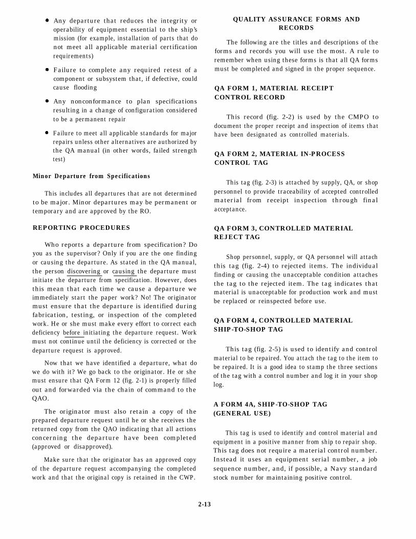
Any departure that reduces the integrity oroperability of equipment essential to the ship’smission (for example, installation of parts that donot meet all applicable material certificationrequirements)
Failure to complete any required retest of acomponent or subsystem that, if defective, couldcause flooding
Any nonconformance to plan specificationsresulting in a change of configuration consideredto be a permanent repair
Failure to meet all applicable standards for majorrepairs unless other alternatives are authorized bythe QA manual (in other words, failed strengthtest)
Minor Departure from Specifications
This includes all departures that are not determinedto be major. Minor departures may be permanent ortemporary and are approved by the RO.
REPORTING PROCEDURES
Who reports a departure from specification? Doyou as the supervisor? Only if you are the one findingor causing the departure. As stated in the QA manual,the person discovering or causing the departure mustinitiate the departure from specification. However, doesthis mean that each time we cause a departure weimmediately start the paper work? No! The originatormust ensure that the departure is identified duringfabrication, testing, or inspection of the completedwork. He or she must make every effort to correct eachdeficiency before initiating the departure request. Workmust not continue until the deficiency is corrected or thedeparture request is approved.
Now that we have identified a departure, what dowe do with it? We go back to the originator. He or shemust ensure that QA Form 12 (fig. 2-1) is properly filledout and forwarded via the chain of command to theQAO.
The originator must also retain a copy of theprepared departure request until he or she receives thereturned copy from the QAO indicating that all actionsconcerning the departure have been completed(approved or disapproved).
Make sure that the originator has an approved copyof the departure request accompanying the completedwork and that the original copy is retained in the CWP.
QUALITY ASSURANCE FORMS ANDRECORDS
The following are the titles and descriptions of theforms and records you will use the most. A rule toremember when using these forms is that all QA formsmust be completed and signed in the proper sequence.
QA FORM 1, MATERIAL RECEIPTCONTROL RECORD
This record (fig. 2-2) is used by the CMPO todocument the proper receipt and inspection of items thathave been designated as controlled materials.
QA FORM 2, MATERIAL IN-PROCESSCONTROL TAG
This tag (fig. 2-3) is attached by supply, QA, or shoppersonnel to provide traceability of accepted controlledmaterial from receipt inspection through finalacceptance.
QA FORM 3, CONTROLLED MATERIALREJECT TAG
Shop personnel, supply, or QA personnel will attachthis tag (fig. 2-4) to rejected items. The individualfinding or causing the unacceptable condition attachesthe tag to the rejected item. The tag indicates thatmaterial is unacceptable for production work and mustbe replaced or reinspected before use.
QA FORM 4, CONTROLLED MATERIALSHIP-TO-SHOP TAG
This tag (fig. 2-5) is used to identify and controlmaterial to be repaired. You attach the tag to the item tobe repaired. It is a good idea to stamp the three sectionsof the tag with a control number and log it in your shoplog.
A FORM 4A, SHIP-TO-SHOP TAG(GENERAL USE)
This tag is used to identify and control material andequipment in a positive manner from ship to repair shop.This tag does not require a material control number.Instead it uses an equipment serial number, a jobsequence number, and, if possible, a Navy standardstock number for maintaining positive control.
2-13

Figure 2-1.-QA Form 12, Departure from Specification Report.
2-14
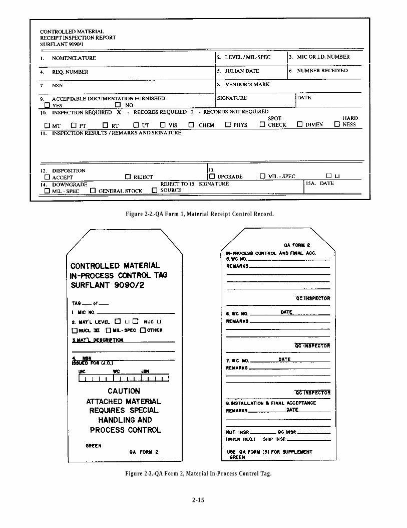
Figure 2-2.-QA Form 1, Material Receipt Control Record.
Figure 2-3.-QA Form 2, Material In-Process Control Tag.
2-15
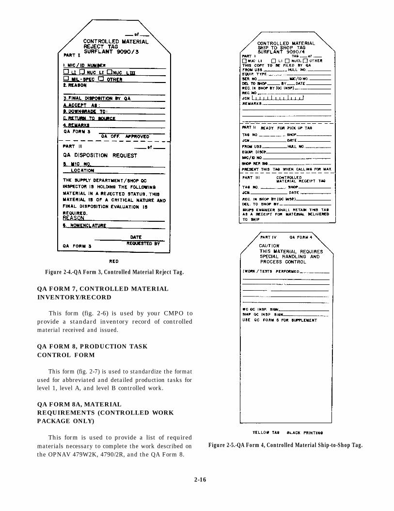
Figure 2-4.-QA Form 3, Controlled Material Reject Tag.
QA FORM 7, CONTROLLED MATERIALINVENTORY/RECORD
This form (fig. 2-6) is used by your CMPO toprovide a standard inventory record of controlledmaterial received and issued.
QA FORM 8, PRODUCTION TASKCONTROL FORM
This form (fig. 2-7) is used to standardize the formatused for abbreviated and detailed production tasks forlevel 1, level A, and level B controlled work.
QA FORM 8A, MATERIALREQUIREMENTS (CONTROLLED WORKPACKAGE ONLY)
This form is used to provide a list of requiredmaterials necessary to complete the work described onthe OPNAV 479W2K, 4790/2R, and the QA Form 8.
Figure 2-5.-QA Form 4, Controlled Material Ship-to-Shop Tag.
2-16
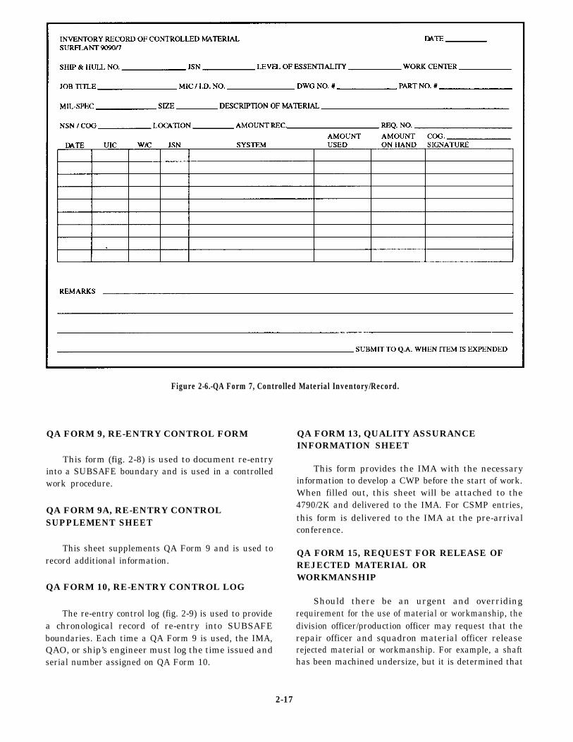
Figure 2-6.-QA Form 7, Controlled Material Inventory/Record.
QA FORM 9, RE-ENTRY CONTROL FORM
This form (fig. 2-8) is used to document re-entryinto a SUBSAFE boundary and is used in a controlledwork procedure.
QA FORM 9A, RE-ENTRY CONTROLSUPPLEMENT SHEET
This sheet supplements QA Form 9 and is used torecord additional information.
QA FORM 10, RE-ENTRY CONTROL LOG
The re-entry control log (fig. 2-9) is used to providea chronological record of re-entry into SUBSAFEboundaries. Each time a QA Form 9 is used, the IMA,QAO, or ship’s engineer must log the time issued andserial number assigned on QA Form 10.
QA FORM 13, QUALITY ASSURANCEINFORMATION SHEET
This form provides the IMA with the necessaryinformation to develop a CWP before the start of work.When filled out, this sheet will be attached to the4790/2K and delivered to the IMA. For CSMP entries,this form is delivered to the IMA at the pre-arrivalconference.
QA FORM 15, REQUEST FOR RELEASE OFREJECTED MATERIAL ORWORKMANSHIP
Should there be an urgent and overridingrequirement for the use of material or workmanship, thedivision officer/production officer may request that therepair officer and squadron material officer releaserejected material or workmanship. For example, a shafthas been machined undersize, but it is determined that
2-17
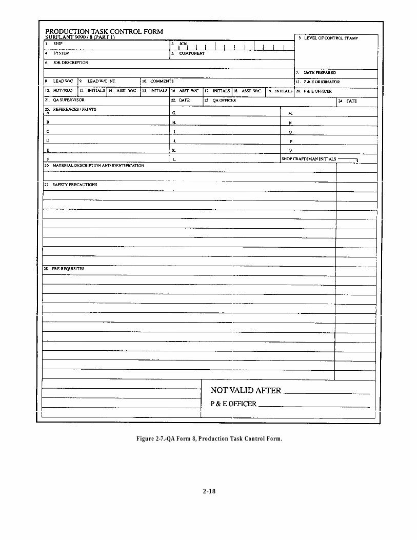
Figure 2-7.-QA Form 8, Production Task Control Form.
2-18
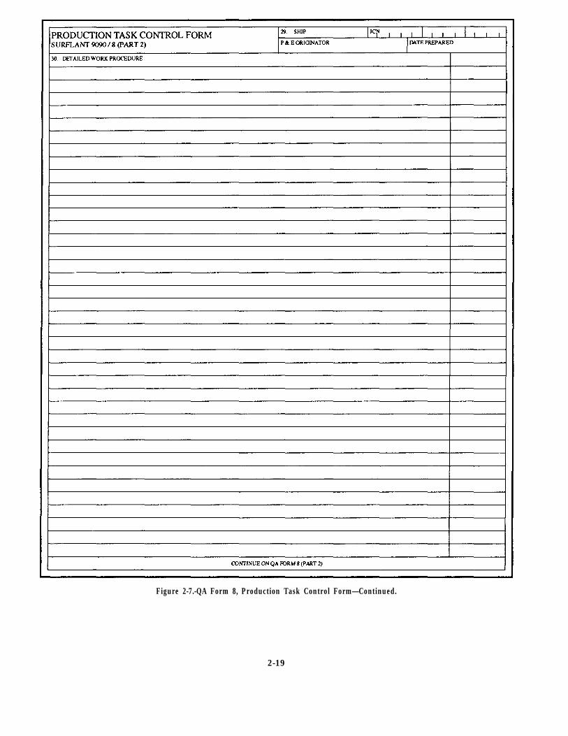
Figure 2-7.-QA Form 8, Production Task Control Form—Continued.
2-19
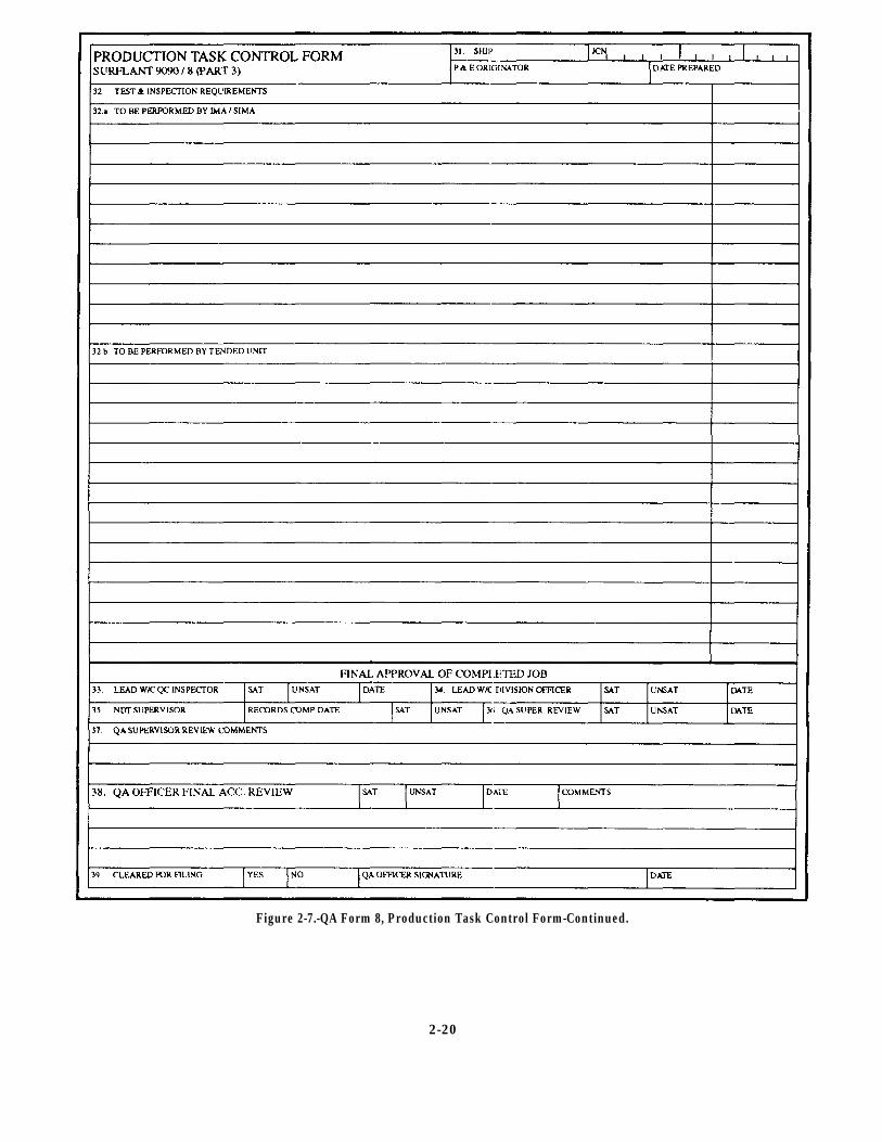
Figure 2-7.-QA Form 8, Production Task Control Form-Continued.
2-20
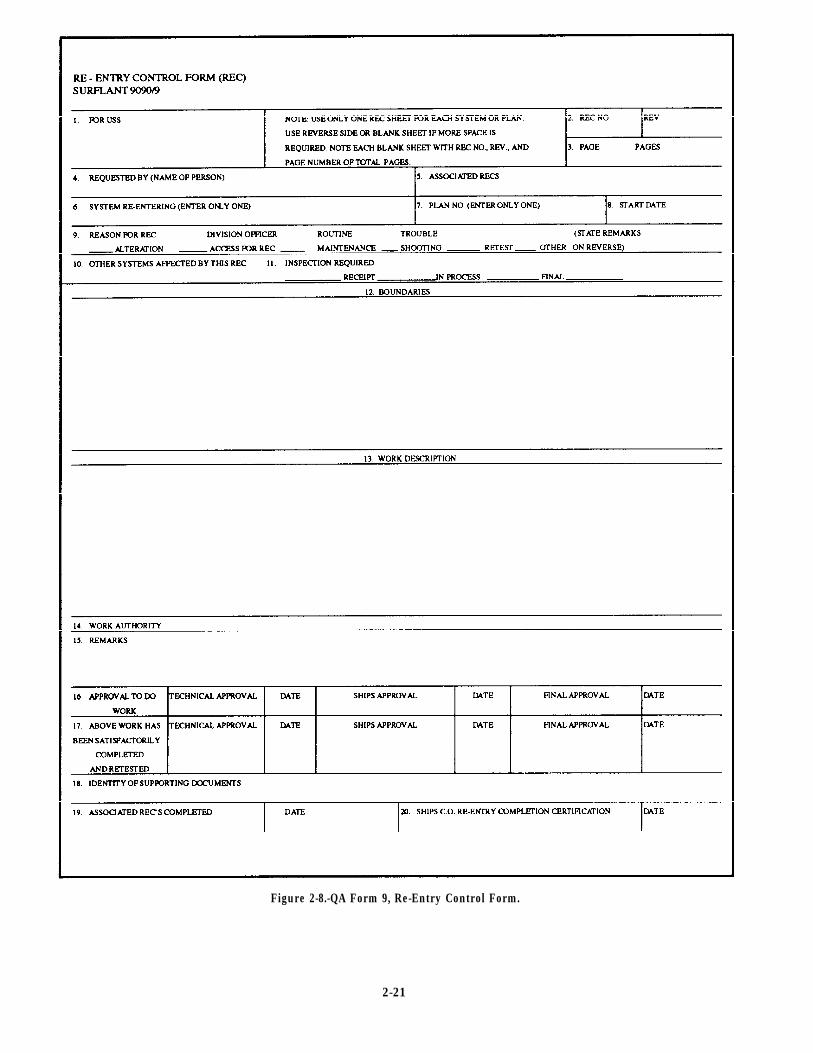
Figure 2-8.-QA Form 9, Re-Entry Control Form.
2-21
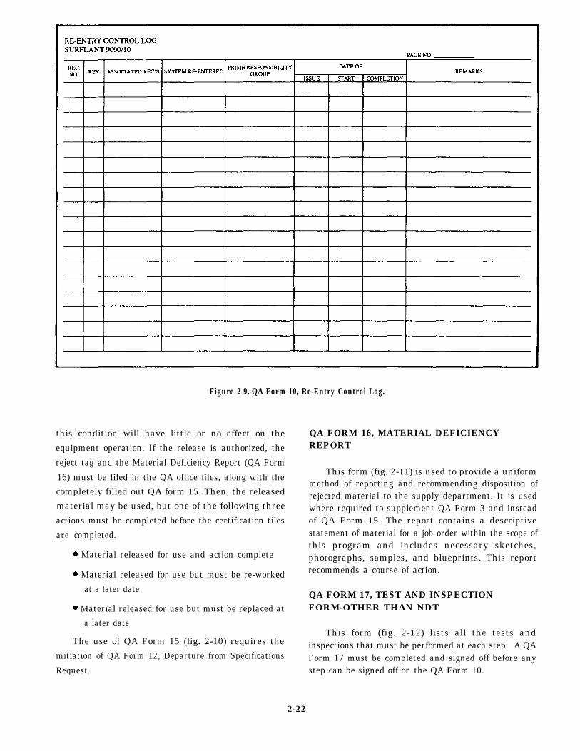
Figure 2-9.-QA Form 10, Re-Entry Control Log.
this condition will have little or no effect on the
equipment operation. If the release is authorized, the
reject tag and the Material Deficiency Report (QA Form
16) must be filed in the QA office files, along with the
completely filled out QA form 15. Then, the released
material may be used, but one of the following three
actions must be completed before the certification tiles
are completed.
Material released for use and action complete
Material released for use but must be re-worked
at a later date
Material released for use but must be replaced at
a later date
The use of QA Form 15 (fig. 2-10) requires the
initiation of QA Form 12, Departure from Specifications
Request.
QA FORM 16, MATERIAL DEFICIENCYREPORT
This form (fig. 2-11) is used to provide a uniformmethod of reporting and recommending disposition ofrejected material to the supply department. It is usedwhere required to supplement QA Form 3 and insteadof QA Form 15. The report contains a descriptivestatement of material for a job order within the scope ofthis program and includes necessary sketches,photographs, samples, and blueprints. This reportrecommends a course of action.
QA FORM 17, TEST AND INSPECTIONFORM-OTHER THAN NDT
This form (fig. 2-12) lists all the tests andinspections that must be performed at each step. A QAForm 17 must be completed and signed off before anystep can be signed off on the QA Form 10.
2-22
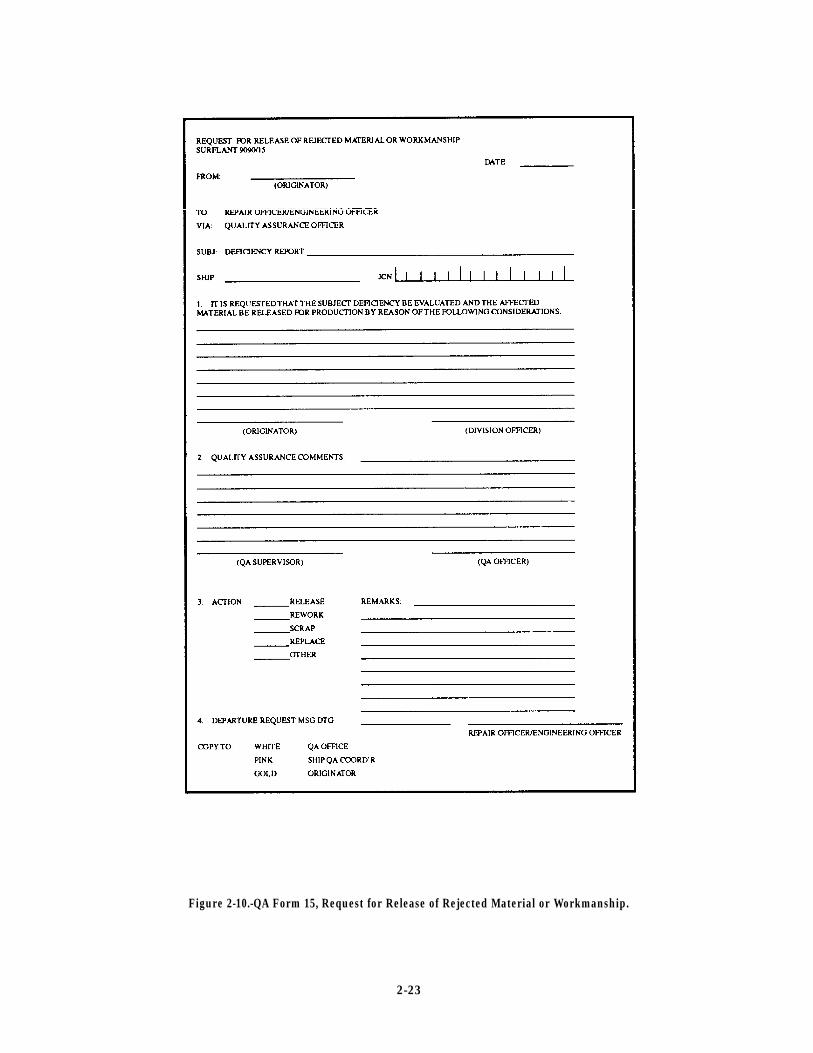
Figure 2-10.-QA Form 15, Request for Release of Rejected Material or Workmanship.
2-23
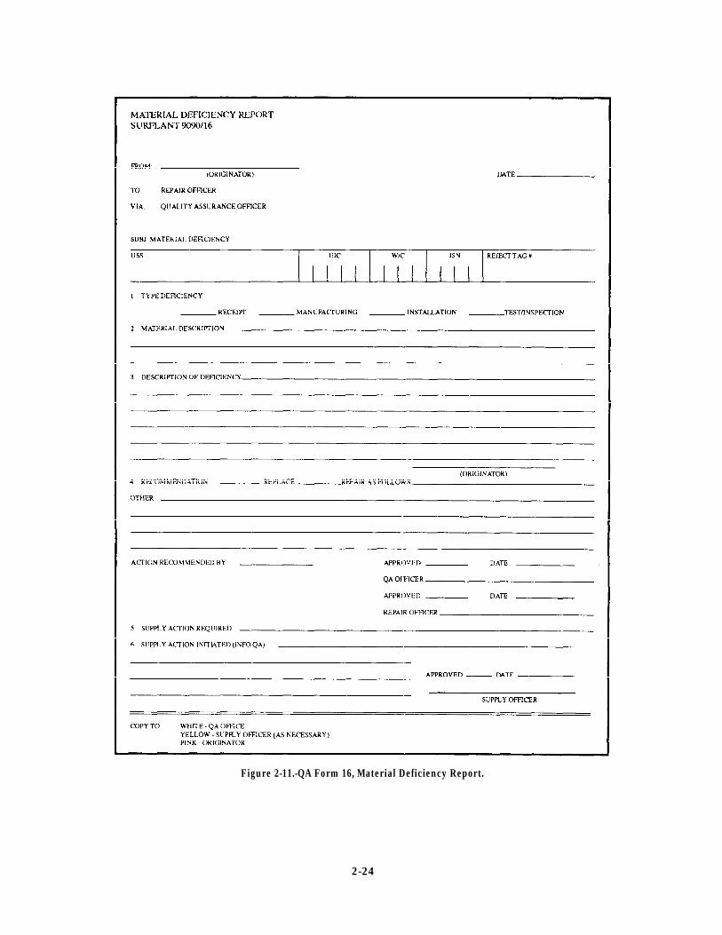
Figure 2-11.-QA Form 16, Material Deficiency Report.
2-24
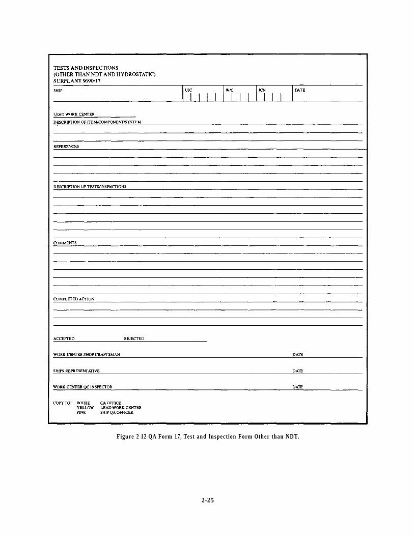
Figure 2-12-QA Form 17, Test and Inspection Form-Other than NDT.
2-25

CHAPTER 3
SHIPS’ DRAWINGS AND DIAGRAMS
LEARNING OBJECTIVES
Upon completion of this chapter, you should be able to do the following:
1. Describe the different types of ships’ drawings. 2. Describe the procedures in verifying the accuracyof ships’ drawings and systems diagrams.
INTRODUCTION
Drawing or sketching is the universal language usedby engineers, technicians, and skilled craftsmen.Whether this drawing is made freehand or with drawinginstruments, it is needed to convey all the necessaryinformation to the individual who will fabricate andassemble the object whether it be a building, a ship, anaircraft, or a mechanical device. If many people areinvolved in the fabrication of the object, copies (prints)are made of the original drawing or tracing so all personsinvolved will have the same information. Not only aredrawings used as plans to fabricate and assembleobjects, they are also used to illustrate how machines,ships, aircraft, and so on are operated, repaired, andmaintained.
The chapter contains general information about thevarious types of ships’ drawing and system diagramsthat you should be familiar with as an IC1 or ICC. Theyinclude the following:
Blueprints
Electrical prints
Electronic prints
Electromechanical drawings
Logic diagrams
As an IC1 or ICC, you should have an indepthknowledge of how to use, care for, update, and verifythe accuracy of these drawings. Drawings have a varietyof uses, and you, as a supervisor, will come to realizethe importance of drawings.
BLUEPRINTS
Blueprints are reproduced copies of mechanical orother types of technical drawings. The term blueprintreading means interpreting the ideas expressed byothers on drawings, whether the drawings are actuallyblueprints or not.
HOW PRINTS ARE MADE
A mechanical drawing is drawn with instrumentssuch as compasses, ruling pens, T-squares, triangles, andfrench curves. Prints (copies) are reproduced fromoriginal drawings in much the same manner asphotographic prints are reproduced from negatives.
The original drawings for prints are made bydrawing directly on, or tracing, a drawing on atranslucent tracing paper or cloth, using blackwaterproof (india) ink or a drawing pencil. This originaldrawing is normally called a tracing “master copy.”These copies of the tracings are rarely, if ever, sent to ashop or job site. Instead, reproductions of these tracingsare made and distributed to persons or offices whereneeded. These tracings can be used over and overindefinitely if properly handled and stored.
Blueprints are made from these tracings. The termblueprints is a rather loosely used term in dealing withreproductions of original drawings. One of the firstprocesses devised to reproduce prints or duplicatetracings produced white lines on a blue background,hence the term blueprints. Today, however, othermethods of reproduction have been developed, and theyproduce prints of different colors. The colors may be
3-1
brown, black, gray, or maroon. The differences are thetypes of paper and the developing processes used.
A patented paper identified as BW paper producesprints with black lines on a white background.
The ammonia process, or OZALIDS, producesprints with either black blue, or maroon lines on a whitebackground.
Other processes that may be used to reproducedrawings, usually small drawings or sketches, are theoffice-type duplicating machines, such as themimeograph and ditto machines. One other type ofduplicating process rarely used for reproducing workingdrawings is the photostatic process in which a largecamera reduces or enlarges a tracing or drawing. Thephotostat has white lines on a dark background whenreproduced directly from a tracing or drawing. If thephotostated print is then reproduced, it will have brownlines on a white background. Photostats are generallyused by various businesses for incorporatingreduced-size drawings into reports or records.
Military drawings and blueprints are preparedaccording to the prescribed standards and procedures inmilitary standards (MIL-STDS). These MIL-STDS arelisted in the Department of Defense Index ofSpecifications and Standards, issued as of 31 July ofeach year. Common MIL-STDS concerningengineering drawings and blueprints most commonlyused by IC Electricians are listed by number and title asfollows:
NUMBER
MIL-STD-100E
MIL-STD-12D
ANSI Y32.2
MIL-STD-15Part No. 2
ANSI Y32.9
MIL-STD-16C
MIL-STD-25A
TITLE
Engineering Drawing Practices
Abbreviations For Use OnDrawings
Graphic Symbols For Electricaland Electronics Diagrams
Electrical Wiring EquipmentSymbols For Ships Plans, Part 2
Electrical Wiring Symbols ForArchitectural and ElectricalLayout Drawings
Electrical and ElectronicReference Designations
Nomenclature and Symbols ForShip Structure
PARTS OF A BLUEPRINT
Military blueprints are prepared as to size, format,location of, information included in various blocks, andso on, according to MIL-STD-100E of 30 September1991. The various parts of a blueprint are describedbriefly in the following paragraphs.
Title Block
The Title block is located in the lower right-handcorner of all blueprints and drawings preparedaccording to MIL-STDs. The block contains thedrawing number, the name of the part or assembly thatthe blueprint represents, and all information required toidentify the part or assembly. The Title block alsoincludes the name and address of the governmentagency or organization preparing the drawing, the scale,drafting record, authentication, and the date (fig. 3-1).
A space within the Title block with a diagonal orslant line drawn across it (not shown in fig. 3-1)indicates that the information usually placed in it is notrequired or is given elsewhere on the drawing.
Revision Block
The Revision block (not shown) is usually locatedin the upper right-hand comer of the blueprint and isused for the recording of changes (revisions) to the print.All revisions are noted in this block and are dated andidentified by a letter and a brief description of therevision. A revised drawing is shown by the addition ofa letter to the original number, as shown in figure 3-1,view A. If the print shown in figure 3-1, view A, wasagain revised, the letter A in the Revision block wouldbe replaced by the letter B.
Drawing Number
All blueprints are identified by a drawing number(NAVSHIP Systems Command number, fig. 3-1, viewA, and Naval Facilities Engineering Command drawingnumber, fig. 3-1, view B), which appears in a block. Itmay be shown in other places also; for example, nearthe top border line in the upper comer, or on the reverseside at both ends so it will be visible when a drawing isrolled up. If a blueprint has more than one sheet, thisinformation is included in the Number block indicatingthe sheet number and the number of sheets in the series.For example, note that in the Title block shown in figure3-1, the sheet is sheet 1 of 1.
3-2
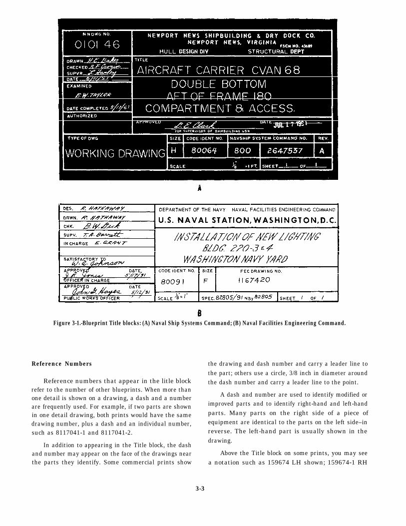
Figure 3-1.-Blueprint Title blocks: (A) Naval Ship Systems Command; (B) Naval Facilities Engineering Command.
Reference Numbers
Reference numbers that appear in the litle blockrefer to the number of other blueprints. When more thanone detail is shown on a drawing, a dash and a numberare frequently used. For example, if two parts are shownin one detail drawing, both prints would have the samedrawing number, plus a dash and an individual number,such as 8117041-1 and 8117041-2.
In addition to appearing in the Title block, the dashand number may appear on the face of the drawings nearthe parts they identify. Some commercial prints show
the drawing and dash number and carry a leader line tothe part; others use a circle, 3/8 inch in diameter aroundthe dash number and carry a leader line to the point.
A dash and number are used to identify modified orimproved parts and to identify right-hand and left-handparts. Many parts on the right side of a piece ofequipment are identical to the parts on the left side–inreverse. The left-hand part is usually shown in thedrawing.
Above the Title block on some prints, you may seea notation such as 159674 LH shown; 159674-1 RH
3-3
opposite. Both parts carry the same number, but the partcalled for is distinguished by a dash and number. (LHmeans left hand and RH means right hand.) Somecompanies use odd numbers for right-hand parts andeven numbers for left-hand parts.
Zone Numbers
Zone numbers on blueprints serve the same purposeas the numbers and letters printed on borders of maps tohelp you locate a particular point. To find a particularpoint, mentally draw horizontal and vertical lines fromthese letters and numerals. The point where these linesintersect is the particular point sought.
You will use practically the same system to help youlocate parts, sections, and views on large blueprintedobjects (for example, assembly drawings on ships’steering gear). Parts numbered in the Title block can belocated on the drawing by looking up the numbers insquares along the lower border. Zone numbers read fromright to left.
Scale
The scale of the blueprint is indicated in one of thespaces within the Title block It indicates the size of thedrawing as compared with the actual size of the part. Thescale may be shown as 1" = 2", 1" = 12", 1/2" = 1', andso on. It also maybe indicated as full size, one-half size,one-fourth size, and so on.
If a blueprint indicates that the scale is 1" = 2", eachline on the print is shown one-half its actual length. If ablueprint indicates that the scale is 3" = 1", each line onthe print is three times its actual length.
Very small parts are enlarged to show the viewsclearly, and large objects are normally reduced in size totit on standard size drawing paper. In short, the scale isselected to fit the object being drawn and the spaceavailable on a sheet of drawing paper.
Remember: NEVER MEASURE A DRAWING.USE DIMENSIONS. Why? Because the print mayhave been reduced in size from the original drawing, oryou might not take the scale of the drawing intoconsideration. Then too, paper stretches and shrinks ashumidity changes, thus introducing perhaps the greatestsource of error in actually taking a measurement bylaying a rule on the print itself. Play it safe and READthe dimensions on the drawing; they always remain thesame.
Graphical scales are often placed on maps and plotplans. These scales indicate the number of feet or miles
represented by an inch. A fraction is often used, such as1/500, meaning that one unit on the map is equal to 500like units on the ground. A LARGE-SCALE MAP hasa scale of 1" = 10"; a map with a scale of 1" = 1,000' isconsidered a SMALL-SCALE MAP.
Various types and shapes of scales are used inpreparing blueprints. Four common types are shown infigure 3-2.
ARCHITECTS’ SCALES.– Architects’ scales(fig. 3-2, view A) are divided into proportional feet andinches and are generally used in scaling drawings formachine and structural work. The triangular architects’scale usually contains 11 scales, each subdivideddifferently. Six scales read from the left end while fivescales read from the right end. Figure 3-2, view A, showshow the 3/16-inch subdivision of the architects’ scale isfurther subdivided into 12 equal parts representing 1inch each, and the 3/32-inch subdivision is furthersubdivided into 6 equal parts representing 2 inches each.
ENGINEERS’ SCALES.– Engineers’ scales (fig.3-2, view B) are divided into decimal graduations (10,20, 30, 40, 50, and 60 divisions to the inch). These scalesare used for plotting and map drawing and in the graphicsolution of problems.
METRIC SCALES.– Metric scales (fig. 3-2, viewC) are used with the drawings, maps, and so forth, madein countries using the metric system. This system is alsobeing used with increasing frequency in the UnitedStates. The scale is divided into centimeters (cm) andmillimeters (mm). In conversion, 2.54 cm are equal to1 inch
GRAPHIC SCALES.– Graphic scales (fig. 3-2,view D) are lines subdivided into distancescorresponding to convenient units of length on theground or of the object represented by the blueprint.They are placed in or near the Title block of the drawingand their relative lengths to the scales of the drawing arenot affected if the print is reduced or enlarged.
Bill of Material Block
The Bill of Material block on a blueprint contains alist of the parts and materials used on or required by theprint concerned. The block identifies parts and materialsby stock number or other appropriate number and liststhe quantity used or required.
The Bill of Material block often contains a list ofstandard parts, known as a parts list or schedule. Manycommonly used items, such as machine bolts, screws,turnbuckles, rivets, pipefittings, and valves, have been
3-4
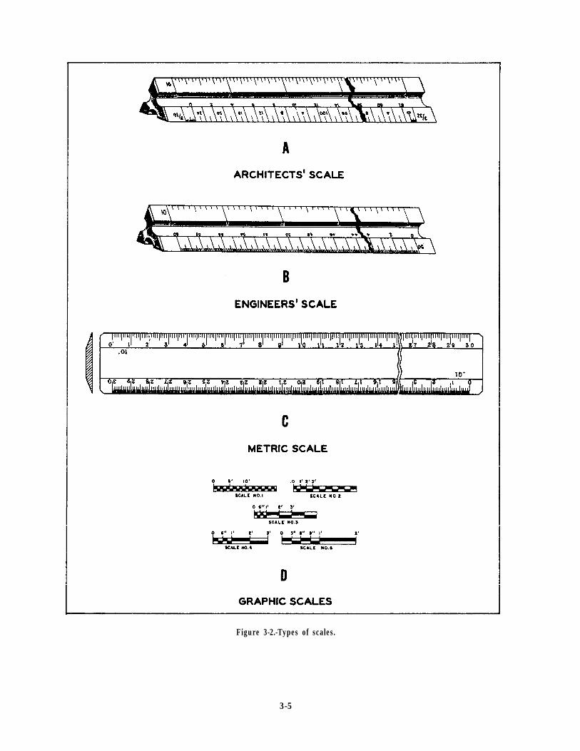
Figure 3-2.-Types of scales.
3-5
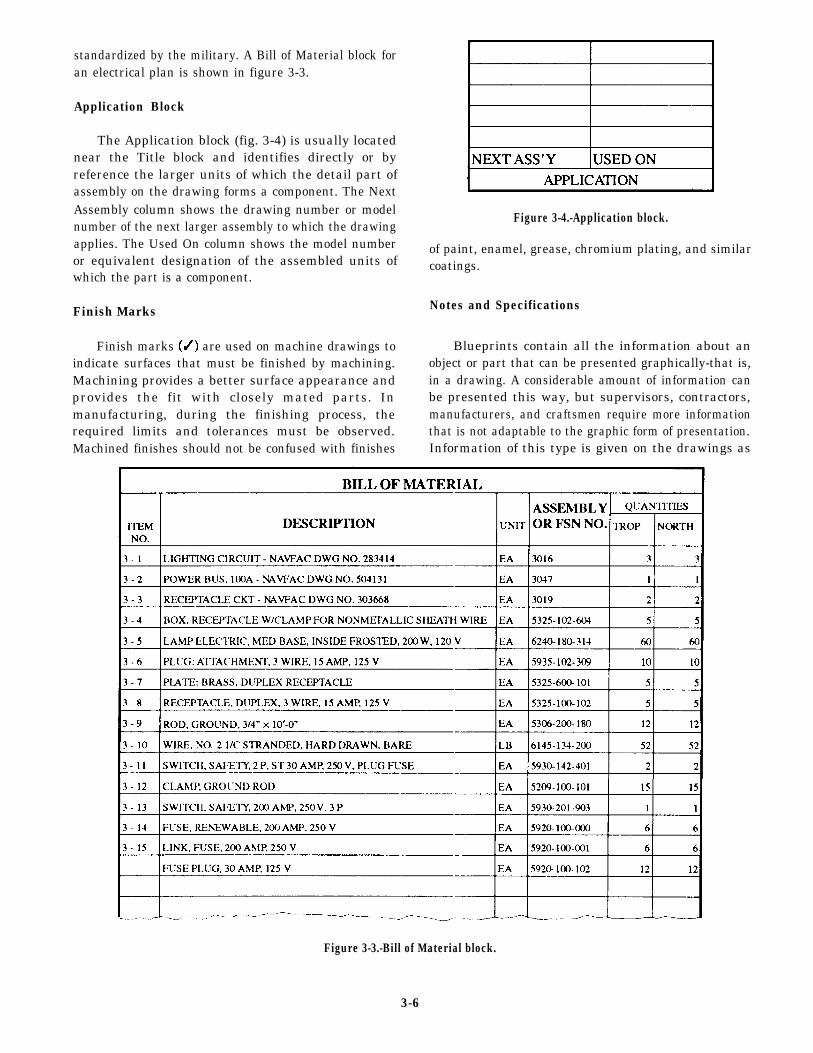
standardized by the military. A Bill of Material block foran electrical plan is shown in figure 3-3.
Application Block
The Application block (fig. 3-4) is usually locatednear the Title block and identifies directly or byreference the larger units of which the detail part ofassembly on the drawing forms a component. The NextAssembly column shows the drawing number or modelnumber of the next larger assembly to which the drawingapplies. The Used On column shows the model numberor equivalent designation of the assembled units ofwhich the part is a component.
Finish Marks
Finish marks are used on machine drawings toindicate surfaces that must be finished by machining.Machining provides a better surface appearance andprovides the fit with closely mated parts. Inmanufacturing, during the finishing process, therequired limits and tolerances must be observed.Machined finishes should not be confused with finishes
Figure 3-4.-Application block.
of paint, enamel, grease, chromium plating, and similarcoatings.
Notes and Specifications
Blueprints contain all the information about anobject or part that can be presented graphically-that is,in a drawing. A considerable amount of information canbe presented this way, but supervisors, contractors,manufacturers, and craftsmen require more informationthat is not adaptable to the graphic form of presentation.Information of this type is given on the drawings as
Figure 3-3.-Bill of Material block.
3-6
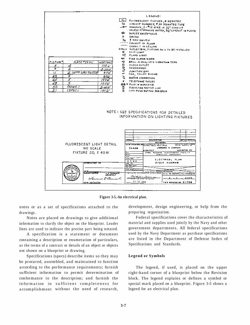
Figure 3-5.-An electrical plan.
notes or as a set of specifications attached to thedrawings.
Notes are placed on drawings to give additionalinformation to clarify the object on the blueprint. Leaderlines are used to indicate the precise part being notated.
A specification is a statement or documentcontaining a description or enumeration of particulars,as the terms of a contract or details of an object or objectsnot shown on a blueprint or drawing.
Specifications (specs) describe items so they maybe procured, assembled, and maintained to functionaccording to the performance requirements; furnishsufficient information to permit determination ofconformance to the description; and furnish theinformation inaccomplishment
sufficient completeness forwithout the need of research,
development, design engineering, or help from thepreparing organization.
Federal specifications cover the characteristics ofmaterial and supplies used jointly by the Navy and othergovernment departments. All federal specificationsused by the Navy Department as purchase specificationsare listed in the Department of Defense Index ofSpecifications and Standards.
Legend or Symbols
The legend, if used, is placed on the upperright-hand corner of a blueprint below the Revisionblock. The legend explains or defines a symbol orspecial mark placed on a blueprint. Figure 3-5 shows alegend for an electrical plan.
3-7
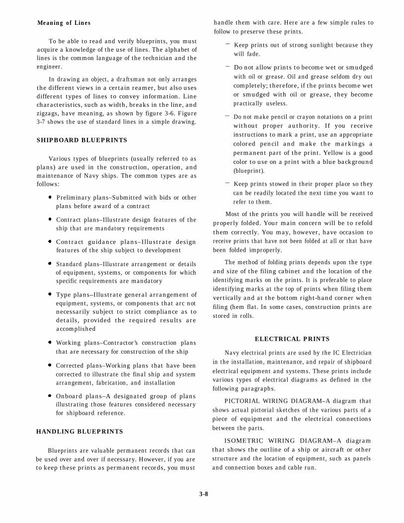
Meaning of Lines
To be able to read and verify blueprints, you mustacquire a knowledge of the use of lines. The alphabet oflines is the common language of the technician and theengineer.
In drawing an object, a draftsman not only arrangesthe different views in a certain reamer, but also usesdifferent types of lines to convey information. Linecharacteristics, such as width, breaks in the line, andzigzags, have meaning, as shown by figure 3-6. Figure3-7 shows the use of standard lines in a simple drawing.
SHIPBOARD BLUEPRINTS
Various types of blueprints (usually referred to asplans) are used in the construction, operation, andmaintenance of Navy ships. The common types are asfollows:
Preliminary plans–Submitted with bids or otherplans before award of a contract
Contract plans–Illustrate design features of theship that are mandatory requirements
Contract guidance plans–Illustrate designfeatures of the ship subject to development
Standard plans–Illustrate arrangement or detailsof equipment, systems, or components for whichspecific requirements are mandatory
Type plans–Illustrate general arrangement ofequipment, systems, or components that arc notnecessarily subject to strict compliance as todetails, provided the required results areaccomplished
Working plans–Contractor’s construction plansthat are necessary for construction of the ship
Corrected plans–Working plans that have beencorrected to illustrate the final ship and systemarrangement, fabrication, and installation
Onboard plans–A designated group of plansillustrating those features considered necessaryfor shipboard reference.
HANDLING BLUEPRINTS
Blueprints are valuable permanent records that canbe used over and over if necessary. However, if you areto keep these prints as permanent records, you must
3-8
handle them with care. Here are a few simple rules tofollow to preserve these prints.
—
—
—
—
Keep prints out of strong sunlight because theywill fade.
Do not allow prints to become wet or smudgedwith oil or grease. Oil and grease seldom dry outcompletely; therefore, if the prints become wetor smudged with oil or grease, they becomepractically useless.
Do not make pencil or crayon notations on a printwithout proper authority. If you receiveinstructions to mark a print, use an appropriatecolored pencil and make the markings apermanent part of the print. Yellow is a goodcolor to use on a print with a blue background(blueprint).
Keep prints stowed in their proper place so theycan be readily located the next time you want torefer to them.
Most of the prints you will handle will be receivedproperly folded. Your main concern will be to refoldthem correctly. You may, however, have occasion toreceive prints that have not been folded at all or that havebeen folded improperly.
The method of folding prints depends upon the typeand size of the filing cabinet and the location of theidentifying marks on the prints. It is preferable to placeidentifying marks at the top of prints when filing themvertically and at the bottom right-hand corner whenfiling (hem flat. In some cases, construction prints arestored in rolls.
ELECTRICAL PRINTS
Navy electrical prints are used by the IC Electricianin the installation, maintenance, and repair of shipboardelectrical equipment and systems. These prints includevarious types of electrical diagrams as defined in thefollowing paragraphs.
PICTORIAL WIRING DIAGRAM–A diagram thatshows actual pictorial sketches of the various parts of apiece of equipment and the electrical connectionsbetween the parts.
ISOMETRIC WIRING DIAGRAM–A diagramthat shows the outline of a ship or aircraft or otherstructure and the location of equipment, such as panelsand connection boxes and cable run.
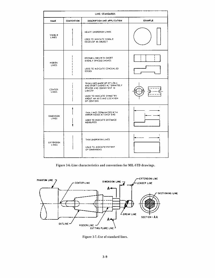
Figure 3-6.-Line characteristics and conventions for MIL-STD drawings.
Figure 3-7.-Use of standard lines.
3-9
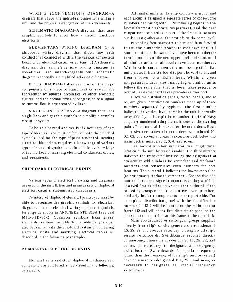
WIRING (CONNECTION) DIAGRAM–Adiagram that shows the individual connections within aunit and the physical arrangement of the components.
SCHEMATIC DIAGRAM–A diagram that usesgraphic symbols to show how a circuit functionselectrically.
ELEMENTARY WIRING DIAGRAM–(1) Ashipboard wiring diagram that shows how eachconductor is connected within the various connectionboxes of an electrical circuit or system. (2) A schematicdiagram; the term elementary wiring diagram issometimes used interchangeably with schematicdiagram, especially a simplified schematic diagram.
BLOCK DIAGRAM–A diagram in which the majorcomponents of a piece of equipment or system arerepresented by squares, rectangles, or other geometricfigures, and the normal order of progression of a signalor current flow is represented by lines.
SINGLE-LINE DIAGRAM–A diagram that usessingle lines and graphic symbols to simplify a complexcircuit or system.
To be able to read and verify the accuracy of anytype of blueprint, you must be familiar with the standardsymbols used for the type of print concerned. Readingelectrical blueprints requires a knowledge of varioustypes of standard symbols and, in addition, a knowledgeof the methods of marking electrical conductors, cables,and equipments.
SHIPBOARD ELECTRICAL PRINTS
Various types of electrical drawings and diagramsare used in the installation and maintenance of shipboardelectrical circuits, systems, and components.
To interpret shipboard electrical prints, you must beable to recognize the graphic symbols for electricaldiagrams and the electrical wiring equipment symbolsfor ships as shown in ANSI/IEEE STD 315A-1986 andMIL-STD-15-2. Common symbols from thesestandards are shown in table 3-1. In addition, you mustalso be familiar with the shipboard system of numberingelectrical units and marking electrical cables asdescribed in the following paragraphs.
NUMBERING ELECTRICAL UNITS
Electrical units and other shipboard machinery andequipment are numbered as described in the followingparagraphs.
All similar units in the ship comprise a group, andeach group is assigned a separate series of consecutivenumbers beginning with 1. Numbering begins in thelowest foremost starboard compartment, and the nextcompartment selected is to port of the first if it containssimilar units; otherwise, the next aft on the same level.
Proceeding from starboard to port and from forwardto aft, the numbering procedure continues until allsimilar units on the same level have been numbered;then it continues on the next upper level, and so on, untilall similar units on all levels have been numbered.Within each compartment, the numbering of similarunits proceeds from starboard to port, forward to aft, andfrom a lower to a higher level. Within a givencompartment, then, the numbering of similar unitsfollows the same rule; that is, lower takes precedenceover aft, and starboard takes precedence over port.
Electrical distribution panels, control panels, and soon, are given identification numbers made up of threenumbers separated by hyphens. The first numberindicates the vertical level, at which the unit is normallyaccessible, by deck or platform number. Decks of Navyships are numbered using the main deck as the startingpoint. The numeral 1 is used for the main deck. Eachsuccessive deck above the main deck is numbered 01,02, 03, and so on, and each successive deck below themain deck is numbered 2, 3, 4, and so on.
The second number indicates the longitudinallocation of the unit by frame number. The third numberindicates the transverse location by the assignment ofconsecutive odd numbers for centerline and starboardlocations and consecutive even numbers for portlocations. The numeral 1 indicates the lowest centerline(or centermost) starboard component. Consecutive oddnun numbers are assigned components as they would beobserved first as being above and then outboard of thepreceding component. Consecutive even numberssimilarly indicate components on the port side. Forexample, a distribution panel with the identificationnumber 1-142-2 will be located on the main deck atframe 142 and will be the first distribution panel on theport side of the centerline at this frame on the main deck.
Main switchboards or switchgear groups supplieddirectly from ship’s service generators are designated1S, 2S, 3S, and soon, as necessary to designate all ship’sservice switchboards. Switchboards supplied directlyby emergency generators are designated 1E, 2E, 3E, andso on, as necessary to designate all emergencyswitchboards. Switchboards for special frequency(other than the frequency of the ship’s service system)have ac generators designated 1SF, 2SF, and so on, asnecessary to designate all special frequencyswitchboards.
3-10
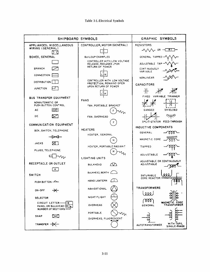
Table 3-1.-Electrical Symbols
3-11
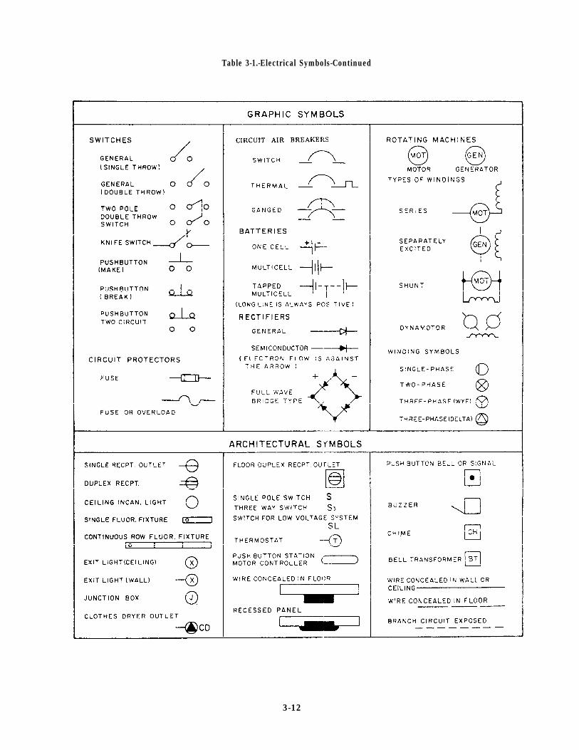
Table 3-1.-Electrical Symbols-Continued
3-12
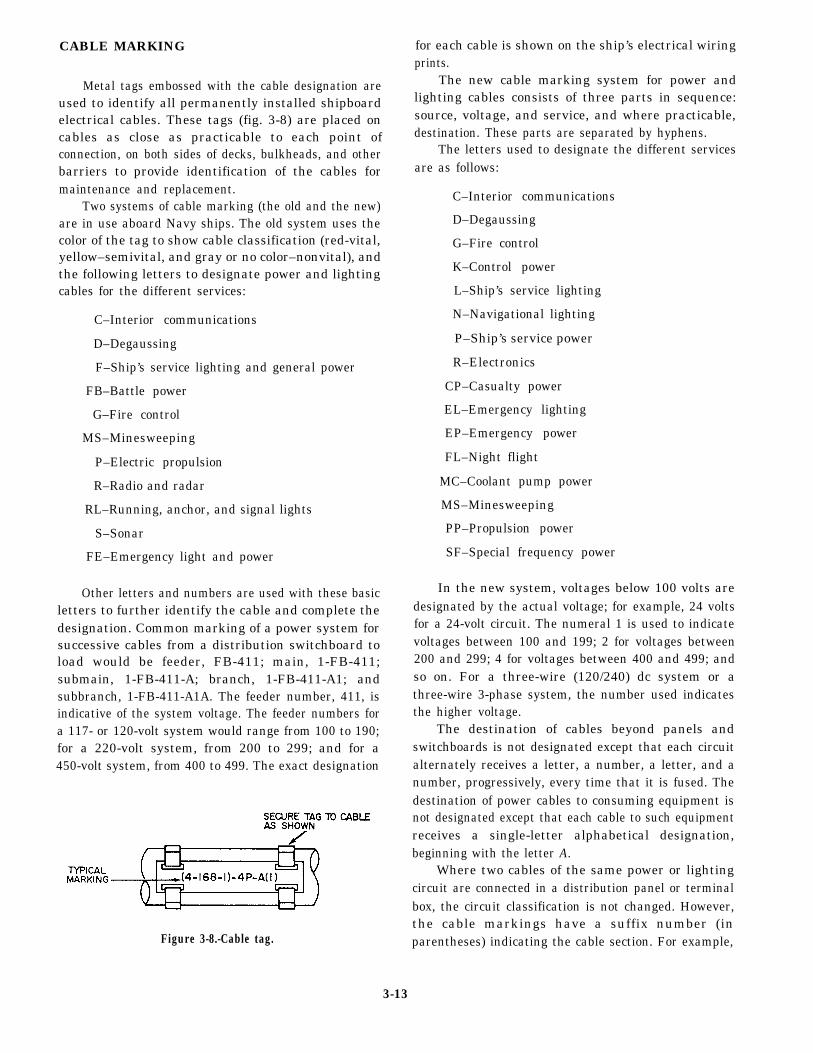
CABLE MARKING
Metal tags embossed with the cable designation areused to identify all permanently installed shipboardelectrical cables. These tags (fig. 3-8) are placed oncables as close as practicable to each point ofconnection, on both sides of decks, bulkheads, and otherbarriers to provide identification of the cables formaintenance and replacement.
Two systems of cable marking (the old and the new)are in use aboard Navy ships. The old system uses thecolor of the tag to show cable classification (red-vital,yellow–semivital, and gray or no color–nonvital), andthe following letters to designate power and lightingcables for the different services:
C–Interior communications
D–Degaussing
F–Ship’s service lighting and general power
FB–Battle power
G–Fire control
MS–Minesweeping
P–Electric propulsion
R–Radio and radar
RL–Running, anchor, and signal lights
S–Sonar
FE–Emergency light and power
Other letters and numbers are used with these basicletters to further identify the cable and complete thedesignation. Common marking of a power system forsuccessive cables from a distribution switchboard toload would be feeder, FB-411; main, 1-FB-411;submain, 1-FB-411-A; branch, 1-FB-411-A1; andsubbranch, 1-FB-411-A1A. The feeder number, 411, isindicative of the system voltage. The feeder numbers fora 117- or 120-volt system would range from 100 to 190;for a 220-volt system, from 200 to 299; and for a450-volt system, from 400 to 499. The exact designation
Figure 3-8.-Cable tag.
for each cable is shown on the ship’s electrical wiringprints.
The new cable marking system for power andlighting cables consists of three parts in sequence:source, voltage, and service, and where practicable,destination. These parts are separated by hyphens.
The letters used to designate the different servicesare as follows:
C–Interior communications
D–Degaussing
G–Fire control
K–Control power
L–Ship’s service lighting
N–Navigational lighting
P–Ship’s service power
R–Electronics
CP–Casualty power
EL–Emergency lighting
EP–Emergency power
FL–Night flight
MC–Coolant pump power
MS–Minesweeping
PP–Propulsion power
SF–Special frequency power
In the new system, voltages below 100 volts aredesignated by the actual voltage; for example, 24 voltsfor a 24-volt circuit. The numeral 1 is used to indicatevoltages between 100 and 199; 2 for voltages between200 and 299; 4 for voltages between 400 and 499; andso on. For a three-wire (120/240) dc system or athree-wire 3-phase system, the number used indicatesthe higher voltage.
The destination of cables beyond panels andswitchboards is not designated except that each circuitalternately receives a letter, a number, a letter, and anumber, progressively, every time that it is fused. Thedestination of power cables to consuming equipment isnot designated except that each cable to such equipmentreceives a single-letter alphabetical designation,beginning with the letter A.
Where two cables of the same power or lightingcircuit are connected in a distribution panel or terminalbox, the circuit classification is not changed. However,the cable markings have a suffix number (inparentheses) indicating the cable section. For example,
3-13
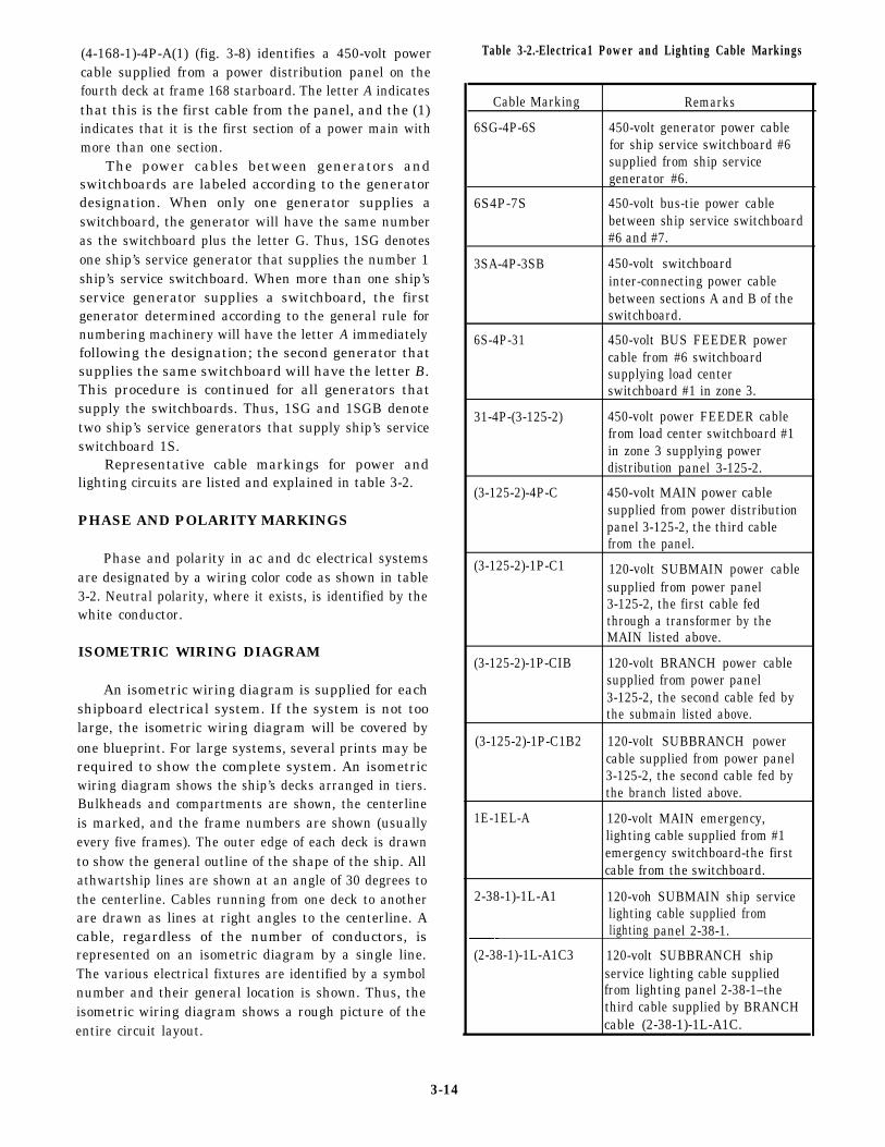
(4-168-1)-4P-A(1) (fig. 3-8) identifies a 450-volt powercable supplied from a power distribution panel on thefourth deck at frame 168 starboard. The letter A indicatesthat this is the first cable from the panel, and the (1)indicates that it is the first section of a power main withmore than one section.
The power cables between generators andswitchboards are labeled according to the generatordesignation. When only one generator supplies aswitchboard, the generator will have the same numberas the switchboard plus the letter G. Thus, 1SG denotesone ship’s service generator that supplies the number 1ship’s service switchboard. When more than one ship’sservice generator supplies a switchboard, the firstgenerator determined according to the general rule fornumbering machinery will have the letter A immediatelyfollowing the designation; the second generator thatsupplies the same switchboard will have the letter B.This procedure is continued for all generators thatsupply the switchboards. Thus, 1SG and 1SGB denotetwo ship’s service generators that supply ship’s serviceswitchboard 1S.
Representative cable markings for power andlighting circuits are listed and explained in table 3-2.
PHASE AND POLARITY MARKINGS
Phase and polarity in ac and dc electrical systemsare designated by a wiring color code as shown in table3-2. Neutral polarity, where it exists, is identified by thewhite conductor.
ISOMETRIC WIRING DIAGRAM
An isometric wiring diagram is supplied for eachshipboard electrical system. If the system is not toolarge, the isometric wiring diagram will be covered byone blueprint. For large systems, several prints may berequired to show the complete system. An isometricwiring diagram shows the ship’s decks arranged in tiers.Bulkheads and compartments are shown, the centerlineis marked, and the frame numbers are shown (usuallyevery five frames). The outer edge of each deck is drawnto show the general outline of the shape of the ship. Allathwartship lines are shown at an angle of 30 degrees tothe centerline. Cables running from one deck to anotherare drawn as lines at right angles to the centerline. Acable, regardless of the number of conductors, isrepresented on an isometric diagram by a single line.The various electrical fixtures are identified by a symbolnumber and their general location is shown. Thus, theisometric wiring diagram shows a rough picture of theentire circuit layout.
Table 3-2.-Electrica1 Power and Lighting Cable Markings
Cable Marking Remarks
6SG-4P-6S 450-volt generator power cablefor ship service switchboard #6supplied from ship servicegenerator #6.
6S4P-7S 450-volt bus-tie power cablebetween ship service switchboard#6 and #7.
3SA-4P-3SB 450-volt switchboardinter-connecting power cablebetween sections A and B of theswitchboard.
6S-4P-31 450-volt BUS FEEDER powercable from #6 switchboardsupplying load centerswitchboard #1 in zone 3.
31-4P-(3-125-2) 450-volt power FEEDER cablefrom load center switchboard #1in zone 3 supplying powerdistribution panel 3-125-2.
(3-125-2)-4P-C 450-volt MAIN power cablesupplied from power distributionpanel 3-125-2, the third cablefrom the panel.
(3-125-2)-1P-C1 120-volt SUBMAIN power cablesupplied from power panel3-125-2, the first cable fedthrough a transformer by theMAIN listed above.
(3-125-2)-1P-CIB 120-volt BRANCH power cablesupplied from power panel3-125-2, the second cable fed bythe submain listed above.
(3-125-2)-1P-C1B2 120-volt SUBBRANCH powercable supplied from power panel3-125-2, the second cable fed bythe branch listed above.
1E-1EL-A 120-volt MAIN emergency,lighting cable supplied from #1emergency switchboard-the firstcable from the switchboard.
2-38-1)-1L-A1 120-voh SUBMAIN ship servicelighting cable supplied fromlighting panel 2-38-1.
(2-38-1)-1L-A1C3 120-volt SUBBRANCH shipservice lighting cable suppliedfrom lighting panel 2-38-1–thethird cable supplied by BRANCHcable (2-38-1)-1L-A1C.
3-14
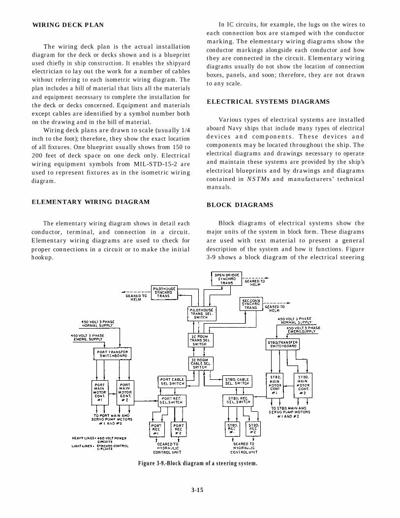
WIRING DECK PLAN
The wiring deck plan is the actual installationdiagram for the deck or decks shown and is a blueprintused chiefly in ship construction. It enables the shipyardelectrician to lay out the work for a number of cableswithout referring to each isometric wiring diagram. Theplan includes a bill of material that lists all the materialsand equipment necessary to complete the installation forthe deck or decks concerned. Equipment and materialsexcept cables are identified by a symbol number bothon the drawing and in the bill of material.
Wiring deck plans are drawn to scale (usually 1/4inch to the foot); therefore, they show the exact locationof all fixtures. One blueprint usually shows from 150 to200 feet of deck space on one deck only. Electricalwiring equipment symbols from MIL-STD-15-2 areused to represent fixtures as in the isometric wiringdiagram.
ELEMENTARY WIRING DIAGRAM
The elementary wiring diagram shows in detail eachconductor, terminal, and connection in a circuit.Elementary wiring diagrams are used to check forproper connections in a circuit or to make the initialhookup.
In IC circuits, for example, the lugs on the wires toeach connection box are stamped with the conductormarking. The elementary wiring diagrams show theconductor markings alongside each conductor and howthey are connected in the circuit. Elementary wiringdiagrams usually do not show the location of connectionboxes, panels, and soon; therefore, they are not drawnto any scale.
ELECTRICAL SYSTEMS DIAGRAMS
Various types of electrical systems are installedaboard Navy ships that include many types of electricaldevices and components. These devices andcomponents may be located throughout the ship. Theelectrical diagrams and drawings necessary to operateand maintain these systems are provided by the ship’selectrical blueprints and by drawings and diagramscontained in NSTMs and manufacturers’ technicalmanuals.
BLOCK DIAGRAMS
Block diagrams of electrical systems show themajor units of the system in block form. These diagramsare used with text material to present a generaldescription of the system and how it functions. Figure3-9 shows a block diagram of the electrical steering
Figure 3-9.-Block diagram of a steering system.
3-15
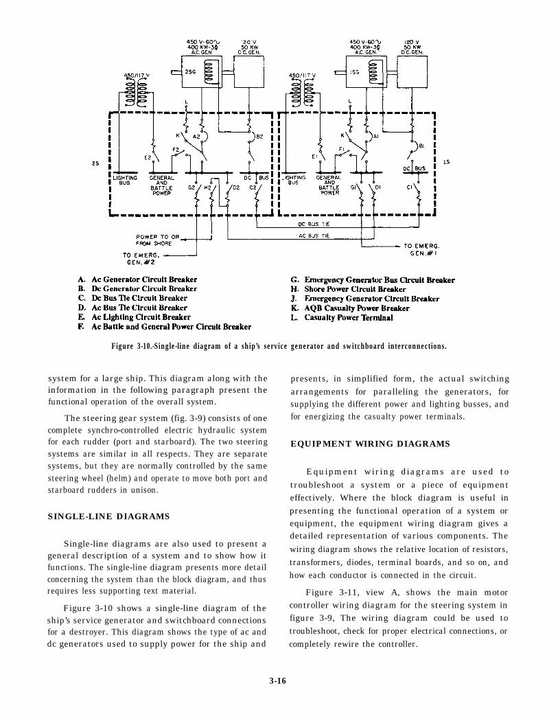
Figure 3-10.-Single-line diagram of a ship’s service generator and switchboard interconnections.
system for a large ship. This diagram along with theinformation in the following paragraph present thefunctional operation of the overall system.
The steering gear system (fig. 3-9) consists of onecomplete synchro-controlled electric hydraulic systemfor each rudder (port and starboard). The two steeringsystems are similar in all respects. They are separatesystems, but they are normally controlled by the samesteering wheel (helm) and operate to move both port andstarboard rudders in unison.
SINGLE-LINE DIAGRAMS
Single-line diagrams are also used to present ageneral description of a system and to show how itfunctions. The single-line diagram presents more detailconcerning the system than the block diagram, and thusrequires less supporting text material.
Figure 3-10 shows a single-line diagram of theship’s service generator and switchboard connectionsfor a destroyer. This diagram shows the type of ac anddc generators used to supply power for the ship and
presents, in simplified form, the actual switchingarrangements for paralleling the generators, forsupplying the different power and lighting busses, andfor energizing the casualty power terminals.
EQUIPMENT WIRING DIAGRAMS
Equipment wiring diagrams are used totroubleshoot a system or a piece of equipmenteffectively. Where the block diagram is useful inpresenting the functional operation of a system orequipment, the equipment wiring diagram gives adetailed representation of various components. Thewiring diagram shows the relative location of resistors,transformers, diodes, terminal boards, and so on, andhow each conductor is connected in the circuit.
Figure 3-11, view A, shows the main motorcontroller wiring diagram for the steering system infigure 3-9, The wiring diagram could be used totroubleshoot, check for proper electrical connections, orcompletely rewire the controller.
3-16
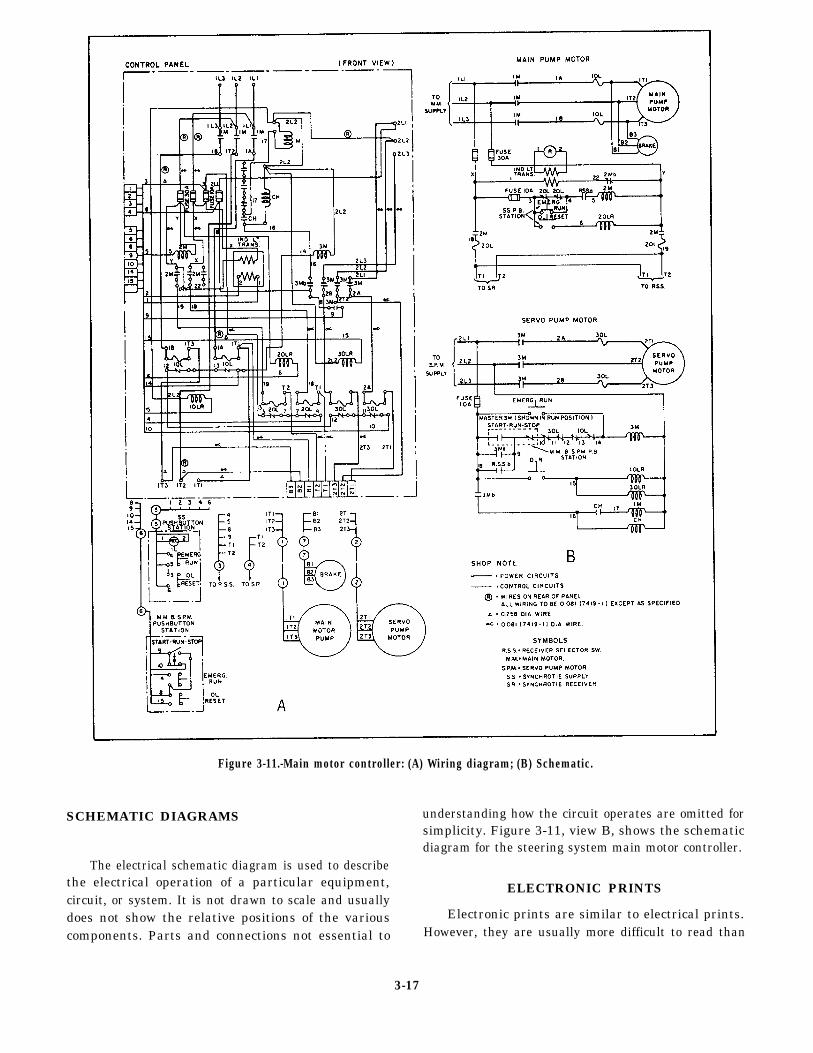
Figure 3-11.-Main motor controller: (A) Wiring diagram; (B) Schematic.
SCHEMATIC DIAGRAMS understanding how the circuit operates are omitted forsimplicity. Figure 3-11, view B, shows the schematicdiagram for the steering system main motor controller.
The electrical schematic diagram is used to describethe electrical operation of a particular equipment,circuit, or system. It is not drawn to scale and usually
ELECTRONIC PRINTS
does not show the relative positions of the various Electronic prints are similar to electrical prints.
components. Parts and connections not essential to However, they are usually more difficult to read than
3-17
electrical prints as they represent more complexcircuitry and systems.
Shipboard electronic prints include isometricwiring diagrams that show the general location ofelectronic units and the interconnecting cable runs, andelementary wiring diagrams that show how each cableis connected. Also included among the common typesof shipboard electronic prints are block diagrams,schematic diagrams, interconnection diagrams,electromechanical drawings, and logic diagrams.
The following paragraphs will discuss only thosediagrams that were not discussed when we coveredelectrical prints.
INTERCONNECTION DIAGRAMS
Interconnection diagrams show the cabling betweenelectronic units and how the units are interconnected.All terminal boards are assigned reference designations.Individual terminals on the terminal boards are assignedletters or numbers or both.
ELECTROMECHANICAL DRAWINGS
Electromechanical devices, such as synchros,gyros, accelerometers, and analog computingelements, are commonly used in IC equipment. For acomplete understanding of these units, neither anelectrical nor a mechanical drawing would besufficient. Therefore, a combination type of drawing
called an electromechanical drawing is used. Thesedrawings are usually simplified both electrically andmechanically, and only those items essential to theoperation are indicated on the drawing.
LOGIC DIAGRAMS
Logic diagrams are used to show the operation oflogic circuits in some IC equipment. They are used inthe operation and maintenance of digital computers.Graphic symbols from American Standard Y32.14 areused.
Basic logic diagrams are used to show the operationof a particular unit or component. Basic logic symbolsare shown in their proper relationship to show operationonly in the most simplified form possible.
Detailed logic diagrams show all logic functions ofthe equipment concerned. In addition, they also includesuch information as socket locations, pin numbers, andtest points to facilitate troubleshooting. The detailedlogic diagram for a complete unit may consist of manyseparate sheets.
All input lines shown on each sheet of detailed logicdiagrams are tagged to show the origin of the inputs.Likewise, all output lines are tagged to show destination.In addition, each logic function shown on the sheet istagged to identify the function hardware and to showfunction location both on the diagram and within theequipment.
3-18
CHAPTER 4
MAINTENANCE
1.
2.
3.
LEARNING OBJECTIVES
Upon completion of this chapter, you should be able to do the following:
Describe the different uses of schematics and 4.drawings by IC Electricians when performingmaintenance.
Describe the principles of testing, repairing, and 5.replacing chassis wiring.
Recognize some of the fundamentals of preventiveand corrective maintenance. 6.
Identify the characteristics of amplifiers used inannouncing systems, and discuss the principles ofimpedance matching.
Identify some of the fundamentals of modularassemblies and parts substitution in maintenancework.
Recognize some of the practices used to maintainand repair IC switchboards.
INTRODUCTION
Since IC Electricians are responsible for preventiveand corrective maintenance of interior communicationssystems, the y must be able to perform tasks such asrepairing chassis wiring, matching speaker impedance,and servicing IC switchboards and associatedequipment. This chapter describes general proceduresfor these tasks and for troubleshooting equipment in ICsystems.
DRAWINGS AND SCHEMATICS
As a senior IC Electrician, you will use your abilityto interpret schematics and drawings proper] y whenaccomplishing your maintenance tasks and whenhelping the less experienced personnel do the same.When working with these people, you will often needsimplified versions of certain schematics and drawings.
Instruction books used by IC Electricians maycontain diagrams of various types of schematicdiagrams, block diagrams, wiring diagrams,interconnecting cable diagrams, mechanical drawings,and combinations of these. Diagrams are normally usedfor presenting information in a small space or forclarifying complex and detailed written explanations.
In chapter 3, we discussed various types of ship’sdrawings and diagrams and the procedures for verifyingthe accuracy of these drawings. The following
paragraphs will discuss the use of these drawings whenyou perform maintenance on IC equipment and systems.
SCHEMATICS
The diagrams IC Electricians use most often are theelectrical and electronic schematics. From pastexperience, they should be familiar with the basicsymbols, the building blocks of the schematics. Thereare new symbols for semiconductors, and futuredevelopments will undoubtedly bring more. GraphicSymbols for Electrical and Electronic Diagrams, USAStandard 432.16, has been adopted for mandatory useby the Department of Defense.
Wiring diagrams and equipment for integratedelectronic systems are complex and require a knowledgeof wire and cable identification markings and symbolsthat show the interconnection of units. Because of theincreased use of computers and electronically controlledand mechanically operated automatic devices, the ICElectrician must recognize symbols and basic principlesto interpret correctly mechanical drawings andelectronic diagrams that show mechanical functions.
A complete schematic drawing of complexequipment may be too large for practical use. For thisreason, most technical manuals present partial orsimplified schematics for individual circuits or units.
4-1
As stated earlier in chapter 3, simplified schematicsnormally omit parts and connections that are notessential to understanding circuit operation. In studyingor troubleshooting equipment, the technician oftenmakes a simplified drawing, including only those itemsthat contribute to the purpose of the drawing. When youare using the schematic drawings in this manual,technical manuals, textbooks, and other publications,notice the various techniques for simplifyingschematics, thereby increasing their usefulness inmaintenance work.
DRAWINGS
The drawings used by an IC Electrician includeblock diagrams, signal flow charts, wiring diagrams,and mechanical drawings. As with schematics, the ICElectrician will be familiar with some drawings frompast experience. The use of block diagrams and signalflow charts to present the overall picture of equipmentfunction is widespread. Although they do not contain thedetails that are needed in accomplishing maintenancetasks, they are obviously valuable in training situationsand in providing overall continuity when personnel areworking with partial schematics.
SYMBOLIC INTEGRATEDMAINTENANCE MANUAL
The IC Electrician is responsible for maintainingmany different types of complex electrical/electronicsequipment, Usually, the diagnostic logic shortcomingsof a young maintenance force result in longer thannecessary equipment downtime. In some cases,equipment damage is introduced by trial-and-errormaintenance actions. Some faults cannot be located andrepaired by the unit level maintenance personnelbecause they lack experience or are not familiar with theequipment. Then too, personnel of all experience levelsare frequently transferred and encounter newequipment. A relatively new troubleshooting aid, theSymbolic Integrated Maintenance Manual (SIMM),should help the troubleshooter identify more readily thegeneral location of a fault. Though this manual presentsa rather complete circuit analysis, in no way does itprevent the requirement for local analysis and awell-informed technician. The SIMM represents a majorchange in the methods of presenting technical data andthe methods of diagnosing electronic system faults.Through the use of new information display techniquesand symbology, blocks, and color shading, the job offault isolation in complex electronic systems is madeeasier, faster, and surer.
The overall objective of the SIMM is to display moredescriptive and illustrative data per page; eliminateunnecessary words, discussion, and illustrations;organize all required data so rapid access is afforded,and display complete circuit element dependencies assimply as possible.
The SIMM helps organize the technical details of anequipment or system, providing users with all theinformation the y need to learn to operate and maintainthe equipment or system. The style of writing and theuse of circuit-identifier codes (coding that assistsrecognition of the circuit character) and coded symbolsenable the trainee to learn faster. Circuit diagrams andassociated text are presented on facing pages.
The text is concise; yet it defines the circuitoperation precisely. Block diagrams relate the level ofphysical containment (unit, assembly, subassembly,sub-subassembly) with the hardware to the functionalcircuits. Associated text is likewise presented on a facingpage. Coded symbols and abbreviations indicate thekind of signals being processed, and circuit-identifiercodes identify the circuit represented by uniquelyshaped blocks. Maintenance dependency charts, basedupon positive logic, provide a unique, fast method oftrouble analysis, include operating procedures, andreveal to a degree the designed-in equipmentmaintainability. The emphasis on symbology, a concisewriting style, and memory devices permit a reduction inpage count with no loss in technical content.
The SIMM is developed around the following threebasic building blocks:
Blocked schematic
Blocked text
Precise-access blocked diagram
BLOCKED SCHEMATIC
By definition, a blocked schematic is a schematicdiagram laid out in block form (fig. 4-1). It distinguishesthe functions and physical aspects of the hardware byusing shaded areas of blue and gray. The blue-shadedareas show the functional features of a circuit (lowestdefinable basic circuit, filter, voltage divider, oscillator,amplifier, relay contact, meter, coil, switch, and so on)and the gray-shaded areas show the hardware (chassis,drawer, module, and so on).
Each blue area includes ALL circuit elements thatare involved in accomplishing the circuit function; theseareas are called functional entities. Each functional
4-2
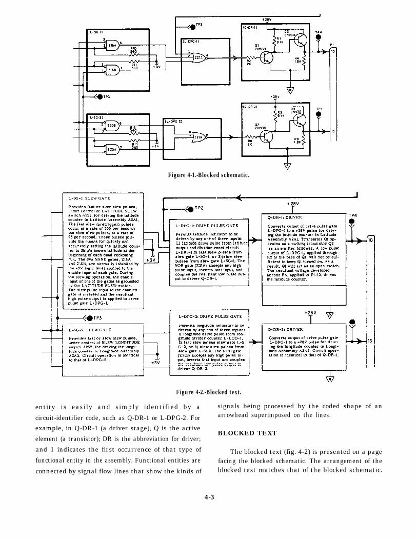
Figure 4-1.-Blocked schematic.
Figure 4-2.-Blocked text.
signals being processed by the coded shape of anentity is easily and simply identified by aarrowhead superimposed on the lines.
BLOCKED TEXT
The blocked text (fig. 4-2) is presented on a pagefacing the blocked schematic. The arrangement of theblocked text matches that of the blocked schematic.
circuit-identifier code, such as Q-DR-1 or L-DPG-2. For
example, in Q-DR-1 (a driver stage), Q is the active
element (a transistor); DR is the abbreviation for driver;
and 1 indicates the first occurrence of that type of
functional entity in the assembly. Functional entities are
connected by signal flow lines that show the kinds of
4-3
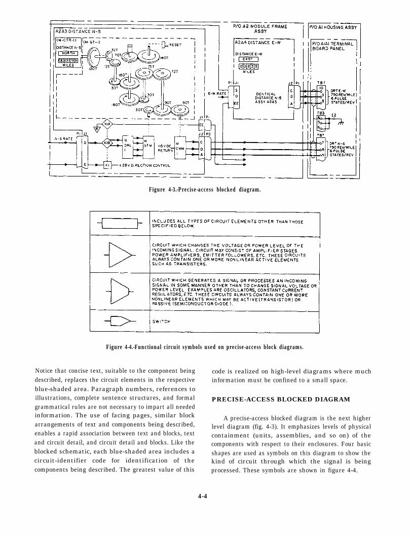
Figure 4-3.-Precise-access blocked diagram.
Figure 4-4.-Functional circuit symbols used on precise-access block diagrams.
Notice that concise text, suitable to the component beingdescribed, replaces the circuit elements in the respectiveblue-shaded area. Paragraph numbers, references toillustrations, complete sentence structures, and formalgrammatical rules are not necessary to impart all neededinformation. The use of facing pages, similar blockarrangements of text and components being described,enables a rapid association between text and blocks, textand circuit detail, and circuit detail and blocks. Like theblocked schematic, each blue-shaded area includes acircuit-identifier code for identification of thecomponents being described. The greatest value of this
code is realized on high-level diagrams where muchinformation must be confined to a small space.
PRECISE-ACCESS BLOCKED DIAGRAM
A precise-access blocked diagram is the next higherlevel diagram (fig. 4-3). It emphasizes levels of physicalcontainment (units, assemblies, and so on) of thecomponents with respect to their enclosures. Four basicshapes are used as symbols on this diagram to show thekind of circuit through which the signal is beingprocessed. These symbols are shown in figure 4-4.
4-4
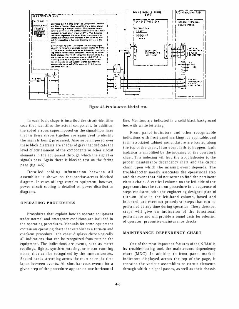
Figure 4-5.-Precise-access blocked text.
In each basic shape is inscribed the circuit-identifiercode that identifies the actual component. In addition,the coded arrows superimposed on the signal-flow linesthat tie these shapes together are again used to identifythe signals being processed. Also superimposed overthese block diagrams are shades of gray that indicate thelevel of containment of the components or other circuitelements in the equipment through which the signal orsignals pass. Again there is blocked text on the facingpage (fig. 4-5).
Detailed cabling information between allassemblies is shown on the precise-access blockeddiagram. In cases of large complex equipment, however,power circuit cabling is detailed on power distributiondiagrams.
OPERATING PROCEDURES
Procedures that explain how to operate equipmentunder normal and emergency conditions are included inthe operating procedures. Manuals for some equipmentcontain an operating chart that establishes a turn-on andcheckout procedure. The chart displays chronologicallyall indications that can be recognized from outside theequipment. The indications are events, such as meterreadings, lights, synchro rotating, or motor runningnoise, that can be recognized by the human senses.Shaded bands stretching across the chart show the timelapse between events. All simultaneous events for agiven step of the procedure appear on one horizontal
line. Monitors are indicated in a solid black backgroundbox with white lettering.
Front panel indicators and other recognizableindications with front panel markings, as applicable, andtheir associated cabinet nomenclature are located alongthe top of the chart, If an event fails to happen, faultisolation is simplified by the indexing on the operator’schart. This indexing will lead the troubleshooter to theproper maintenance dependency chart and the circuitchain upon which the missing event depends. Thetroubleshooter merely associates the operational stepand the event that did not occur to find the pertinentcircuit chain. A vertical column on the left side of thepage contains the turn-on procedure in a sequence ofsteps consistent with the engineering designed plan ofturn-on. Also in the left-hand column, boxed andindented, are checkout procedural steps that can beperformed at any time during operation. These checkoutsteps will give an indication of the functionalperformance and will provide a sound basis for selectionof operator, preventive-maintenance checks.
MAINTENANCE DEPENDENCY CHART
One of the most important features of the SIMM isits troubleshooting tool, the maintenance dependencychart (MDC). In addition to front panel markedindicators displayed across the top of the page, itcontains the various assemblies or circuit elementsthrough which a signal passes, as well as their chassis
4-5
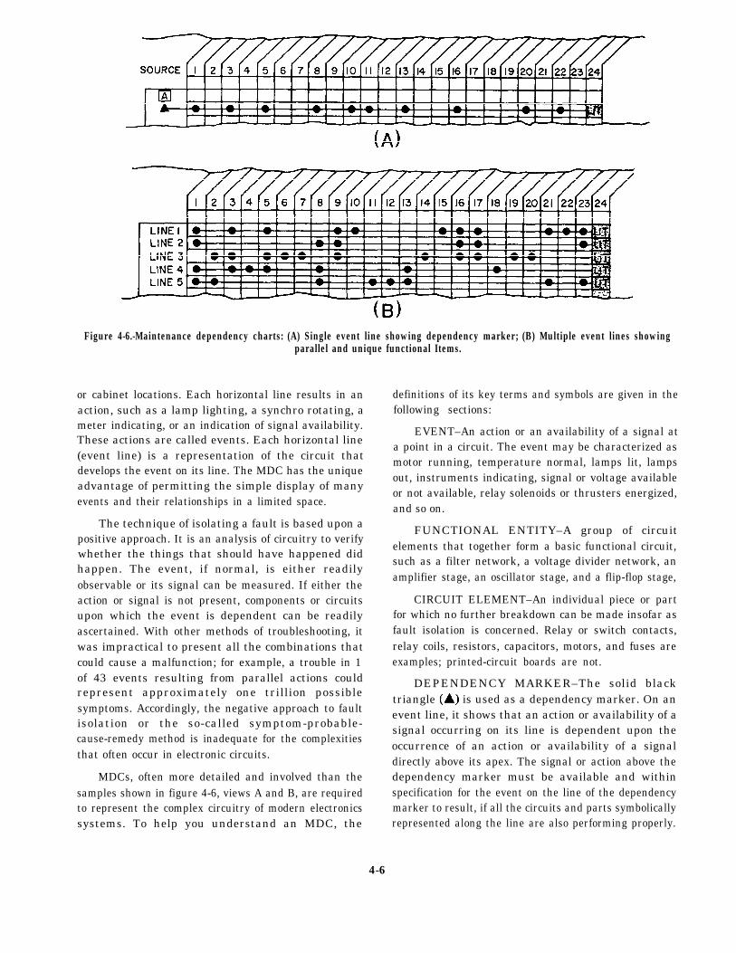
Figure 4-6.-Maintenance dependency charts: (A) Single event line showing dependency marker; (B) Multiple event lines showingparallel and unique functional Items.
or cabinet locations. Each horizontal line results in anaction, such as a lamp lighting, a synchro rotating, ameter indicating, or an indication of signal availability.These actions are called events. Each horizontal line(event line) is a representation of the circuit thatdevelops the event on its line. The MDC has the uniqueadvantage of permitting the simple display of manyevents and their relationships in a limited space.
The technique of isolating a fault is based upon apositive approach. It is an analysis of circuitry to verifywhether the things that should have happened didhappen. The event, if normal, is either readilyobservable or its signal can be measured. If either theaction or signal is not present, components or circuitsupon which the event is dependent can be readilyascertained. With other methods of troubleshooting, itwas impractical to present all the combinations thatcould cause a malfunction; for example, a trouble in 1of 43 events resulting from parallel actions couldrepresent approximately one trillion possiblesymptoms. Accordingly, the negative approach to faultisolation or the so-called symptom-probable-cause-remedy method is inadequate for the complexitiesthat often occur in electronic circuits.
MDCs, often more detailed and involved than thesamples shown in figure 4-6, views A and B, are requiredto represent the complex circuitry of modern electronicssystems. To help you understand an MDC, the
definitions of its key terms and symbols are given in thefollowing sections:
EVENT–An action or an availability of a signal ata point in a circuit. The event may be characterized asmotor running, temperature normal, lamps lit, lampsout, instruments indicating, signal or voltage availableor not available, relay solenoids or thrusters energized,and so on.
FUNCTIONAL ENTITY–A group of circuitelements that together form a basic functional circuit,such as a filter network, a voltage divider network, anamplifier stage, an oscillator stage, and a flip-flop stage,
CIRCUIT ELEMENT–An individual piece or partfor which no further breakdown can be made insofar asfault isolation is concerned. Relay or switch contacts,relay coils, resistors, capacitors, motors, and fuses areexamples; printed-circuit boards are not.
DEPENDENCY MARKER–The solid blacktriangle is used as a dependency marker. On anevent line, it shows that an action or availability of asignal occurring on its line is dependent upon theoccurrence of an action or availability of a signaldirectly above its apex. The signal or action above thedependency marker must be available and withinspecification for the event on the line of the dependencymarker to result, if all the circuits and parts symbolicallyrepresented along the line are also performing properly.
4-6
A solid black rectangle and white lettering representa front panel indicator or an event recognizable fromoutside the cabinetry; an outlined rectangle with blacklettering is a circuit point at which measurement mightat some time be made. This circuit point may not bereadily accessible. Internal test points that are readilyaccessible will be shown as gray-shaded rectangles.
The dot (·) represents a circuit element or afunctional entity. One aspect or state of circuit orcomponent is represented by (·), and relay contacts areshown by (/·) or (·/), for continuity with relay energizedor de-energized, respectively.
HOW TO USE THE MAINTENANCEDEPENDENCY CHART
Assume that in the illustration of a signal event line,figure 4-6, view A, dots (·) represent the basic circuits(oscillator stages, amplifier stages, and soon) or circuitelements (relay contacts, relay cards, and so on) thatprovide an action LIT at the end of a circuit chain (eventline). The solid triangle is a dependency marker.
The action LIT depends on the availability of apower source at the A block and on the proper operationof each of the circuits or circuit elements (·) representedalong the event line. Now, if the lamp that indicates theaction fails to light, any item along the event line, as wellas the source, A, is a suspect item. Complex interrelatedcircuits often use some of the same circuits or circuitelements for more than one purpose. Thus, in multiplecircuits, where many functional items are common tomore than one circuit chain (event line), as shown infigure 4-6, view B, notice that actions (column 24) thatoccur at the end of these circuit chains are a result ofcertain common items employed in the parallelgeneration of the events shown on other circuit lines andsome items that are unique to a single line.
Look again at the multiple event line illustration(fig. 4-6, view B) for the purpose of analysis. If the lampdoes not light on line 4 but does light on lines 1, 2, 3,and 5, it becomes apparent that the circuits or circuitelements represented by the dots in columns 4 and 18are the only ones that can be suspected as faulty. Allitems represented by dots in other columns are provengood because of the proper occurrence of the action LITon lines 1, 2, 3, and 5.
For each major circuit, consistent with theprecise-access blocked diagrams and blockedschematics, there is a corresponding MDC.Troubleshooting is accomplished by analyzing the
charts. Faults must lie between the first bad event andthe last good event. Acetate coverings for MDCs maybe provided, or the charts maybe plasticized, so a greaseor carbon pencil can be used for marking out areas thatprove good. Marking out all known areas and actionsthat can be proven good rapidly reveals suspect areas.The use of a pencil to mark out all proven good items isrecommended because technicians cannot normallyremember all the areas or dependencies that they haveproven good.
INDEXING OF RELATED INFORMATION
Indexing is another important feature of the SIMM.The SIMM method of indexing (fig. 4-7) allows accessto any bit of information relative to an assembly in amatter of seconds. The index is organized on the basisof major assemblies and then is broken down to thecontained assemblies. Since each of the assemblies isfull y treated within a four- or six-page data package, andthe organization of details is always consistent, accessto the desired kind of detail is almost immediate. TheMDC is used to identify the functional entity or circuitelement that is suspected, the assembly in which it iscontained, and the cabinet containing the assembly.Accordingly, in using the index you need only find thecabinet nomenclature and look to the page number forthe contained assembly data package.
ALIGNMENT PROCEDURES
Alignment procedures for each functional sectionof the set or system, as necessary, are included on as fewpages as possible. The method of identifying alignmentprocedures is the same as for making otheridentifications from the MDC. The alignmentprocedures are directly keyed from the signalspecifications listed on the MDC. If a particular eventshown on the MDC is below specification andcorrectable by alignment, the step in the alignment chartis easy to find. Each part of the MDC treats a majorfunctional segment of equipment. Likewise, thealignment actions are organized (charted) for each majorfictional segment of the equipment. The identificationsystem for the charts is used for the alignment procedurechart. For example, alignments that affect events on theMDC, part 2, will be found on the alignment chart, part2, and so on. When required, alignment ofsubassemblies outside the set environment will becontained with the other details of individual assembliesin the data package for the assembly.
4-7
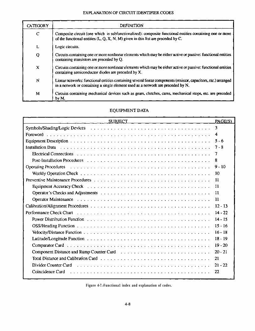
Figure 4-7.-Functiona1 index and explanation of codes.
4-8
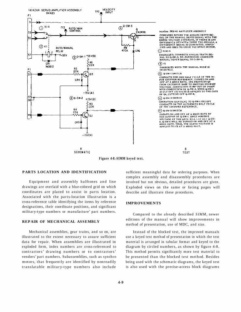
Figure 4-8.-SIMM keyed text.
PARTS LOCATION AND IDENTIFICATION
Equipment and assembly halftones and linedrawings are overlaid with a blue-colored grid on whichcoordinates are placed to assist in parts location.Associated with the parts-location illustration is across-reference table identifying the items by referencedesignations, their coordinate positions, and significantmilitary-type numbers or manufacture’ part numbers.
REPAIR OF MECHANICAL ASSEMBLY
Mechanical assemblies, gear trains, and so on, areillustrated to the extent necessary to assure sufficientdata for repair. When assemblies are illustrated inexploded form, index numbers are cross-referenced tocontractors’ drawing numbers or to contractors’vendors’ part numbers. Subassemblies, such as synchromotors, that frequently are identified by nonreadilytranslatable military-type numbers also include
sufficient meaningful data for ordering purposes. Whencomplex assembly and disassembly procedures areinvolved but not obvious, detailed procedures are given.Exploded views on the same or facing pages willdescribe and illustrate these procedures.
IMPROVEMENTS
Compared to the already described SIMM, newereditions of the manual will show improvements inmethod of presentation, use of MDC, and size.
Instead of the blocked text, the improved manualsuse a keyed text method of presentation in which the textmaterial is arranged in tabular format and keyed to thediagram by circled numbers, as shown by figure 4-8.This method permits significantly more text material tobe presented than the blocked text method. Besidesbeing used with the schematic diagrams, the keyed textis also used with the precise-access block diagrams
4-9
(called functional block diagrams) and the overall blockdiagrams (called the function description diagrams).
Instead of only one MDC for each major function,newer manuals will have additional MDCs for thefunctional block and schematic diagrams. The MDCsalso will be provided with an acetate or Mylar overlayso troubleshooters can use grease pencils to mark theirprogress. The size of the new SIMM will be 11 by 27inches, instead of 15 by 35 inches. This new size givesit a folded dimension of 9 by 11 inches, the same size asconventional manuals.
CHASSIS WIRING
Chassis wiring is loosely defined as the wire orwires installed in an equipment cabinet that interconnectthe assemblies of the cabinet. Chassis wiring varies inapplication and size of run. It may range from a harnessor run of two wires, used in sound-powered amplifiersand telephone cases, to large cable runs, such as thosein MC cabinets, dial telephone switchboards, and gyrobinnacles. IC Electricians must be able to test, repair,and replace chassis wiring, regardless of its run size andapplication.
TESTING CHASSIS WIRING
In testing chassis wiring, it is not possible tosubstitute for good common sense. Your first step intesting chassis wiring of a faulty piece of equipmentshould always be a detailed visual inspection of thewiring harness, from terminal to terminal. A completevisual check will save you many hours of work lookingfor trouble that you could have detected in the first placeby inspecting the equipment for visible damage. Ifcertain wires are obviously at fault, you should replacethem before going any further in the test.
Your sense of smell can help in pinpointing burnedor damaged wire that you may not see when making thevisual inspection. Most burned electrical insulation willgive off a noticeable, unpleasant odor that is readilydetectable. The location of a burned wire, however, doesnot necessarily reveal the cause of the trouble.
Signal tracing is the most reliable method oflocating shorts, opens, or grounds in chassis wiring. Thebest method of making continuity tests for shorts andgrounds in chassis wiring calls for the use of amultimeter and manufacturers’ instruction books.
REPAIRING CHASSIS WIRING
A major consideration in repairing chassis wiring isthe amount of time you have to complete the repair andget the equipment back in operation. If the equipment isto be “down” for a long time, be sure the repair iscompleted correctly. As a temporary repair, it ispermissible to run a straight wire instead of followingthe original cable run. This temporary lead should besoldered in place, after you disconnect the faulty lead.This practice should only be done when there isinsufficient time to make the proper repairs.
When a few wires are to be replaced, lace them tothe outside of the existing cable run. When many wiresare to be replaced, remove the damaged wiring andre-run the new wires along the route of the old cable run.After connecting the wires, you should lace or clampthem in their original positions.
You should avoid unnecessary slack in the cableruns and always try to keep your repairs neat andworkmanlike. A properly replaced wire or cable run alsowill make it easier to trace later.
REPLACING CHASSIS WIRING
Sometimes your personnel may have to replacechassis wiring in components of IC systems, such as21MC units. Chassis wiring is usually the last part to failin electronic equipment, but it can wear out from minorfriction and abrasion in the course of making otherrepairs, or it can be damaged by a malfunction thatcauses overheating or fire.
Individual leads in chassis wiring must be replacedwire for wire. This is a tedious job, but one that requiresonly skill with a soldering iron. A wiring harnesscontaining damaged wires is best repaired by replacingit with a prefabricated harness. Prefabricating areplacement harness is usually easier than repairingindividual wires in the old harness. An installed harnessis hard to work on, and soldering on it may damage otherwiring insulation or electronic components. If the unitto be repaired is still in working order, the replacementharness can be made, and then installed whenever it isconvenient to have the unit off the line.
Tee first step in making a wiring harness is to makea wiring form or jig, as shown in figure 4-9. Build theform on a sheet of 1/4-inch plywood, using small (6d)finishing nails. Using a plastic ruler, measure theoriginal harness and chassis in the unit to be repaired.Your measurements should let you outline the chassisand the location of the harness run and mark the
4-10
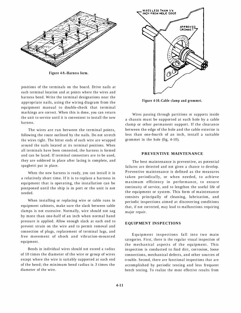
Figure 4-9.–Harness form.
positions of the terminals on the board. Drive nails ateach terminal location and at points where the wires andharness bend. Write the terminal designations near theappropriate nails, using the wiring diagram from theequipment manual to double-check that terminalmarkings are correct. When this is done, you can returnthe unit to service until it is convenient to install the newharness.
The wires are run between the terminal points,following the route outlined by the nails. Do not stretchthe wires tight. The bitter ends of each wire are wrappedaround the nails located at its terminal positions. Whenall terminals have been connected, the harness is formedand can be laced. If terminal connectors are to be used,they are soldered in place after lacing is complete, andspaghetti put in place.
When the new harness is ready, you can install it ina relatively short time. If it is to replace a harness inequipment that is operating, the installation can bepostponed until the ship is in port or the unit is notneeded.
When installing or replacing wire or cable runs inequipment cabinets, make sure the slack between cableclamps is not excessive. Normally, wire should not sagby more than one-half of an inch when normal handpressure is applied. Allow enough slack at each end toprevent strain on the wire and to permit removal andconnection of plugs, replacement of terminal lugs, andfree movement of shock and vibration-mountedequipment.
Bends in individual wires should not exceed a radiusof 10 times the diameter of the wire or group of wiresexcept where the wire is suitably supported at each endof the bend; the minimum bend radius is 3 times thediameter of the wire.
Figure 4-10.-Cable clamp and grommet.
Wires passing through partitions or supports insidea chassis must be supported at each hole by a cableclamp or other permanent support. If the clearancebetween the edge of the hole and the cable exterior isless than one-fourth of an inch, install a suitablegrommet in the hole (fig, 4-10).
PREVENTIVE MAINTENANCE
The best maintenance is preventive, as potentialfailures are detected and not given a chance to develop.Preventive maintenance is defined as the measurestaken periodically, or when needed, to achievemaximum efficiency in performance, to ensurecontinuity of service, and to lengthen the useful life ofthe equipment or system. This form of maintenanceconsists principally of cleaning, lubrication, andperiodic inspections aimed at discovering conditionsthat, if not corrected, may lead to malfunctions requiringmajor repair.
EQUIPMENT INSPECTIONS
Equipment inspections fall into two maincategories. First, there is the regular visual inspection ofthe mechanical aspects of the equipment. Thisinspection is conducted to find dirt, corrosion, looseconnections, mechanical defects, and other sources oftrouble. Second, there are functional inspections that areaccomplished by periodic testing and less frequentbench testing. To realize the most effective results from
4-11
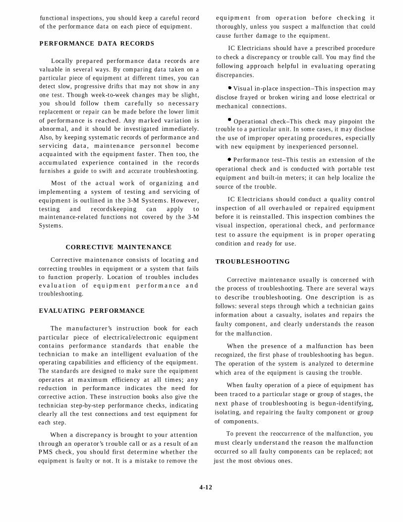
functional inspections, you should keep a careful recordof the performance data on each piece of equipment.
PERFORMANCE DATA RECORDS
Locally prepared performance data records arevaluable in several ways. By comparing data taken on aparticular piece of equipment at different times, you candetect slow, progressive drifts that may not show in anyone test. Though week-to-week changes may be slight,you should follow them carefully so necessaryreplacement or repair can be made before the lower limitof performance is reached. Any marked variation isabnormal, and it should be investigated immediately.Also, by keeping systematic records of performance andservicing data, maintenance personnel becomeacquainted with the equipment faster. Then too, theaccumulated experience contained in the recordsfurnishes a guide to swift and accurate troubleshooting.
Most of the actual work of organizing andimplementing a system of testing and servicing ofequipment is outlined in the 3-M Systems. However,testing and recordskeeping can apply tomaintenance-related functions not covered by the 3-MSystems.
CORRECTIVE MAINTENANCE
Corrective maintenance consists of locating andcorrecting troubles in equipment or a system that failsto function properly. Location of troubles includesevaluation of equipment performance andtroubleshooting.
EVALUATING PERFORMANCE
The manufacturer’s instruction book for eachparticular piece of electrical/electronic equipmentcontains performance standards that enable thetechnician to make an intelligent evaluation of theoperating capabilities and efficiency of the equipment.The standards are designed to make sure the equipmentoperates at maximum efficiency at all times; anyreduction in performance indicates the need forcorrective action. These instruction books also give thetechnician step-by-step performance checks, indicatingclearly all the test connections and test equipment foreach step.
When a discrepancy is brought to your attentionthrough an operator’s trouble call or as a result of anPMS check, you should first determine whether theequipment is faulty or not. It is a mistake to remove the
equipment from operation before checking itthoroughly, unless you suspect a malfunction that couldcause further damage to the equipment.
IC Electricians should have a prescribed procedureto check a discrepancy or trouble call. You may find thefollowing approach helpful in evaluating operatingdiscrepancies.
Visual in-place inspection–This inspection maydisclose frayed or broken wiring and loose electrical ormechanical connections.
Operational check–This check may pinpoint thetrouble to a particular unit. In some cases, it may disclosethe use of improper operating procedures, especiallywith new equipment by inexperienced personnel.
Performance test–This testis an extension of theoperational check and is conducted with portable testequipment and built-in meters; it can help localize thesource of the trouble.
IC Electricians should conduct a quality controlinspection of all overhauled or repaired equipmentbefore it is reinstalled. This inspection combines thevisual inspection, operational check, and performancetest to assure the equipmentcondition and ready for use.
TROUBLESHOOTING
is in proper operating
Corrective maintenance usually is concerned withthe process of troubleshooting. There are several waysto describe troubleshooting. One description is asfollows: several steps through which a technician gainsinformation about a casualty, isolates and repairs thefaulty component, and clearly understands the reasonfor the malfunction.
When the presence of a malfunction has beenrecognized, the first phase of troubleshooting has begun.The operation of the system is analyzed to determinewhich area of the equipment is causing the trouble.
When faulty operation of a piece of equipment hasbeen traced to a particular stage or group of stages, thenext phase of troubleshooting is begun-identifying,isolating, and repairing the faulty component or groupof components.
To prevent the reoccurrence of the malfunction, youmust clearly understand the reason the malfunctionoccurred so all faulty components can be replaced; notjust the most obvious ones.
4-12
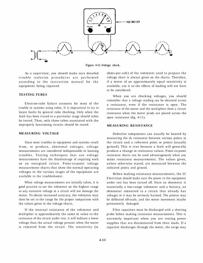
Figure 4-11.-Voltage check.
As a supervisor, you should make sure detailedtrouble isolation procedures are performedaccording to the instruction manual for theequipment being repaired.
TESTING TUBES
Electron-tube failure accounts for most of thetrouble in systems using tubes. It is impractical to try tolocate faults by general tube checking. Only when thefault has been traced to a particular stage should tubesbe tested. Then, only those tubes associated with theimproperly functioning circuits should be tested.
MEASURING VOLTAGE
Since most troubles in equipment and systems resultfrom, or produce, abnormal voltages, voltagemeasurements are considered indispensable in locatingtroubles. Testing techniques that use voltagemeasurements have the disadvantage of requiring workon an energized circuit. Point-to-point voltagemeasurement charts that show the normal operatingvoltages in the various stages of the equipment areavailable to the troubleshooter.
When voltage measurements are initially taken, it isgood practice to set the voltmeter on the highest rangeso any excessive voltage in a circuit will not damage themeter. To obtain increased accuracy, the voltmeter maythen be set to the range for the proper comparison withthe values given in the voltage charts.
If the internal resistance of the voltmeter andmultiplier is approximately the same in value to theresistance of the circuit under test, it will indicate a lowervoltage than the actual voltage present when the meteris removed from the circuit. The sensitivity (in
ohms-per-volt) of the voltmeter used to prepare thevoltage chart is always given on the charts. Therefore,if a meter of an approximately equal sensitivity isavailable, use it so the effects of loading will not haveto be considered.
When you are checking voltages, you shouldremember that a voltage reading can be obtained acrossa resistance, even if the resistance is open. Theresistance of the meter and the multipliers form a circuitresistance when the meter prods are placed across theopen resistance (fig. 4-11).
MEASURING RESISTANCE
Defective components can usually be located bymeasuring the dc resistance between various points inthe circuit and a reference point or points (usuallyground). This is true because a fault will generallyproduce a change in resistance values. Point-to-pointresistance charts can be used advantageously when youmake resistance measurements. The values given,unless otherwise stated, are measured between theindicated points and ground.
Before making resistance measurements, the ICElectrician should make sure the power to the equipmentunder test has been turned off. Since an ohmmeter isessentially a low-range voltmeter and a battery, anohmmeter connected to a circuit that already hasvoltages in it may be seriously harmed. The pointer maybe deflected off-scale, and the meter movement maybepermanently damaged.
Filter capacitors must be discharged with a shortingprobe before making resistance measurements. This isextremely important when you are testing powersupplies that are disconnected from their loads. If acapacitor discharges through the meter, the surge may
4-13
burn out the meter movement. Furthermore, contactwith a circuit containing a charged capacitor willendanger the life of the person making the test.
COMPARING WAVEFORMS
The measurement and comparison of waveformsare considered to be very important parts of the circuitanalysis used in troubleshooting. In some circuits (forexample, pulse circuits), waveform analysis isindispensable. Waveforms may be observed at testpoints, shown in the waveform charts that are part of themaintenance literature for the equipment. You shouldnote that the waveforms given in the instruction booksare often idealized and do not show some of the detailsthat are normally present when the actual waveform isdisplayed on an oscilloscope.
By comparing the observed waveform with thereference waveform, faults can be localized rapidly. Adeparture from the normal waveform indicates a faultthat is located between the point where the waveform islast seen to be normal and the point where it is observedto be abnormal. (For example, if a waveform is observedto be normal at the grid circuit and abnormal at the platecircuit of the same stage, this indicates that the troublelies in that stage or possibly the input of the followingstage.)
If there is no trouble present in an equipment orsystem, a waveform observed at a point in the equipmentshould closely resemble the reference waveform givenfor that test point. The reference waveforms suppliedwith maintenance literature are the criteria of properequipment performance. However, test equipmentcharacteristics of usage can cause distortion of theobserved waveform, though the equipment or system isoperating normally. Several of the most common causesof these conditions are summarized in the followingsections:
The leads of the test oscilloscope may not beplaced in the same manner as those preparing thereference waveforms, or the lead lengths may differconsiderably. This is particularly significant in shieldedtest leads, where the capacitance per unit length is afactor.
A type of test oscilloscope having differentvalues of input impedance, different sweep durations, ordifferent frequency response may have been used.
The equipment operating (and servicing)controls may not have settings identical to those usedwhen the reference waveforms were prepared. This
condition is normally to be expected when servicingadjustments are made in terms of their effect on theshape and amplitude of an observed waveform.
The vertical or horizontal amplitudes of thereference and test patterns may not be proportional. Thiswill produce apparent differences between thewaveforms when actually there is no difference.
Whether or not a minor waveform discrepancy maybe disregarded depends upon the type of circuit beingtraced. A minor discrepancy is not regarded assignificant unless the nature of the discrepancy indicatesfaulty operation of the equipment. In general, timeshould not be wasted in searching for faults whenrelatively minor differences are detected between thereference waveforms and those obtained by test.
AMPLIFIERS IN ANNOUNCING SYSTEMS
In purchasing a public address system, where youalready know its power requirements, locations andtypes of microphones, and number and types ofspeakers, you may have to decide between a system thatuses vacuum-tube amplifiers or one that uses transistoramplifiers. Your decision should be based on factorsother than relative costs. Here are some reasons for theuse of transistor amplifiers instead of vacuum-tubeamplifiers:
– The life of a transistor is longer than that of avacuum tube.
– Transistors consume less power than vacuumtubes.
– Transistor amplifiers use dc power moreefficiently than vacuum-tube amplifiers.
– Transistors operate more efficiently at lowvoltages than vacuum tubes.
– Microphonics signals generated by shock orvibrations are almost completely lacking in transistors.
– Power is instantly available at the throw of aswitch.
– Ac hum is minimized.
On the other hand, vacuum-tube amplifiers offerthese advantages over transistor amplifiers:
– Vacuum-tube replacements take less time thantransistor replacements.
– Vacuum-tube amplifiers are less likely to beaffected by high ambient temperatures or to suffer heatdamage.
4-14
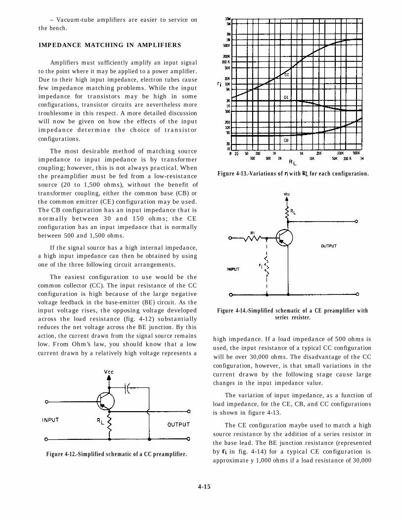
– Vacuum-tube amplifiers are easier to service onthe bench.
IMPEDANCE MATCHING IN AMPLIFIERS
Amplifiers must sufficiently amplify an input signalto the point where it may be applied to a power amplifier.Due to their high input impedance, electron tubes causefew impedance matching problems. While the inputimpedance for transistors may be high in someconfigurations, transistor circuits are nevertheless moretroublesome in this respect. A more detailed discussionwill now be given on how the effects of the inputimpedance determine the choice of transistorconfigurations.
The most desirable method of matching sourceimpedance to input impedance is by transformercoupling; however, this is not always practical. Whenthe preamplifier must be fed from a low-resistancesource (20 to 1,500 ohms), without the benefit oftransformer coupling, either the common base (CB) orthe common emitter (CE) configuration may be used.The CB configuration has an input impedance that isnormally between 30 and 150 ohms; the CEconfiguration has an input impedance that is normallybetween 500 and 1,500 ohms.
If the signal source has a high internal impedance,a high input impedance can then be obtained by usingone of the three following circuit arrangements.
The easiest configuration to use would be thecommon collector (CC). The input resistance of the CCconfiguration is high because of the large negativevoltage feedback in the base-emitter (BE) circuit. As theinput voltage rises, the opposing voltage developedacross the load resistance (fig. 4-12) substantiallyreduces the net voltage across the BE junction. By thisaction, the current drawn from the signal source remainslow. From Ohm’s law, you should know that a lowcurrent drawn by a relatively high voltage represents a
Figure 4-12.-Simplified schematic of a CC preamplifier.
Figure 4-13.-Variations of with for each configuration.
Figure 4-14.-Simplified schematic of a CE preamplifier withseries resister.
high impedance. If a load impedance of 500 ohms isused, the input resistance of a typical CC configurationwill be over 30,000 ohms. The disadvantage of the CCconfiguration, however, is that small variations in thecurrent drawn by the following stage cause largechanges in the input impedance value.
The variation of input impedance, as a function ofload impedance, for the CE, CB, and CC configurationsis shown in figure 4-13.
The CE configuration maybe used to match a highsource resistance by the addition of a series resistor inthe base lead. The BE junction resistance (representedby in fig. 4-14) for a typical CE configuration isapproximate y 1,000 ohms if a load resistance of 30,000
4-15
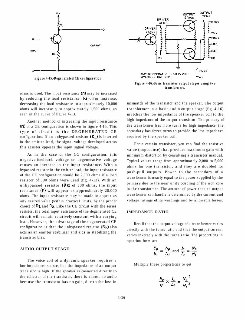
Figure 4-15.-Degenerated CE configuration.
ohms is used. The input resistance may be increasedby reducing the load resistance For instance,decreasing the load resistance to approximately 10,000ohms will increase to approximately 1,500 ohms, asseen in the curve of figure 4-13.
Another method of increasing the input resistance of a CE configuration is shown in figure 4-15. This
type of circuit is the DEGENERATED CEconfiguration. If an unbypassed resistor is insertedin the emitter lead, the signal voltage developed acrossthis resistor opposes the input signal voltage.
As in the case of the CC configuration, thisnegative-feedback voltage or degenerative voltagecauses an increase in the input resistance. With abypassed resistor in the emitter lead, the input resistanceof the CE configuration would be 2,000 ohms if a loadresistor of 500 ohms were used (fig. 4-13). With anunbypassed resistor of 500 ohms, the inputresistance will appear as approximately 20,000ohms. The input resistance may be made to appear asany desired value (within practical limits) by the properchoice of and Like the CE circuit with the seriesresistor, the total input resistance of the degenerated CEcircuit will remain relatively constant with a varyingload. However, the advantage of the degenerated CEconfiguration is that the unbypassed resistor alsoacts as an emitter stabilizer and aids in stabilizing thetransistor bias.
AUDIO OUTPUT STAGE
The voice coil of a dynamic speaker requires alow-impedance source, but the impedance of an outputtransistor is high. If the speaker is connected directly tothe collector of the transistor, there is almost no audiobecause the transistor has no gain, due to the loss in
Figure 4-16.-Basic transistor output stages using twotransformers.
mismatch of the transistor and the speaker. The outputtransformer in a basic audio output stage (fig. 4-16)matches the low impedance of the speaker coil to thehigh impedance of the output transistor. The primary ofthe transformer has more turns for high impedance; thesecondary has fewer turns to provide the low impedancerequired by the speaker coil.
For a certain transistor, you can find the resistivevalue (impedance) that provides maximum gain withminimum distortion by consulting a transistor manual.Typical values range from approximately 2,000 to 5,000ohms for one transistor, and they are doubled forpush-pull outputs. Power to the secondary of atransformer is nearly equal to the power supplied by theprimary due to the near unity coupling of the iron corein the transformer. The amount of power that an outputtransformer can handle is determined by the current andvoltage ratings of its windings and by allowable losses.
IMPEDANCE RATIO
Recall that the output voltage of a transformer variesdirectly with the turns ratio and that the output currentvaries inversely with the turns ratio. The proportions inequation form are
Multiply these proportions to get
4-16
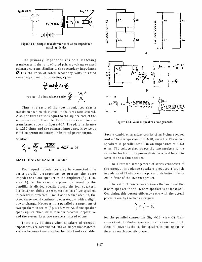
Figure 4-17.-Output transformer used as an Impedancematching device.
The primary impedance (Z) of a matchingtransformer is the ratio of rated primary voltage to ratedprimary current. Similarly, the secondary impedance
is the ratio of rated secondary volts to ratedsecondary current. Substituting for
you get the impedance ratio
Thus, the ratio of the two impedances that atransformer can match is equal to the turns ratio squared.Also, the turns ratio is equal to the square root of theimpedance ratio. Example: Find the turns ratio for thetransformer shown in figure 4-17. The plate resistanceis 1,250 ohms and the primary impedance is twice asmuch to permit maximum undistorted power output.
Solution:
MATCHING SPEAKER LOADS
Four equal impedances may be connected in aseries-parallel arrangement to present the sameimpedance as one speaker to the amplifier (fig. 4-18,view A). In this case, the power delivered by theamplifier is divided equally among the four speakers.For better reliability, a series connection of two speakersin parallel is preferred. Should one speaker open up, theother three would continue to operate, but with a slightpower change. However, in a parallel arrangement oftwo speakers in series (fig. 4-18, view A), if one speakeropens up, its other series member becomes inoperativeand the system loses two speakers instead of one.
There may be times when speakers of unequalimpedances are coordinated into an impedance-matchedsystem because they may be the only kind available.
Figure 4-18.-Various speaker arrangements.
Such a combination might consist of an 8-ohm speakerand a 16-ohm speaker (fig. 4-18, view B). These twospeakers in parallel result in an impedance of 5 1/3ohms. The voltage drop across the two speakers is thesame for both and the power division would be 2:1 infavor of the 8-ohm speaker.
The alternate arrangement of series connection ofthe unequal-impedance speakers produces a branchimpedance of 24 ohms with a power distribution that is2:1 in favor of the 16-ohm speaker.
The ratio of power conversion efficiencies of the8-ohm speaker to the 16-ohm speaker is at least 5:1.Combining this output efficiency ratio with the actualpower taken by the two units gives
for the parallel connection (fig. 4-18, view C). Thisshows that the 8-ohm speaker, taking twice as muchelectrical power as the 16-ohm speaker, is putting out 10times as much acoustic power.
4-17
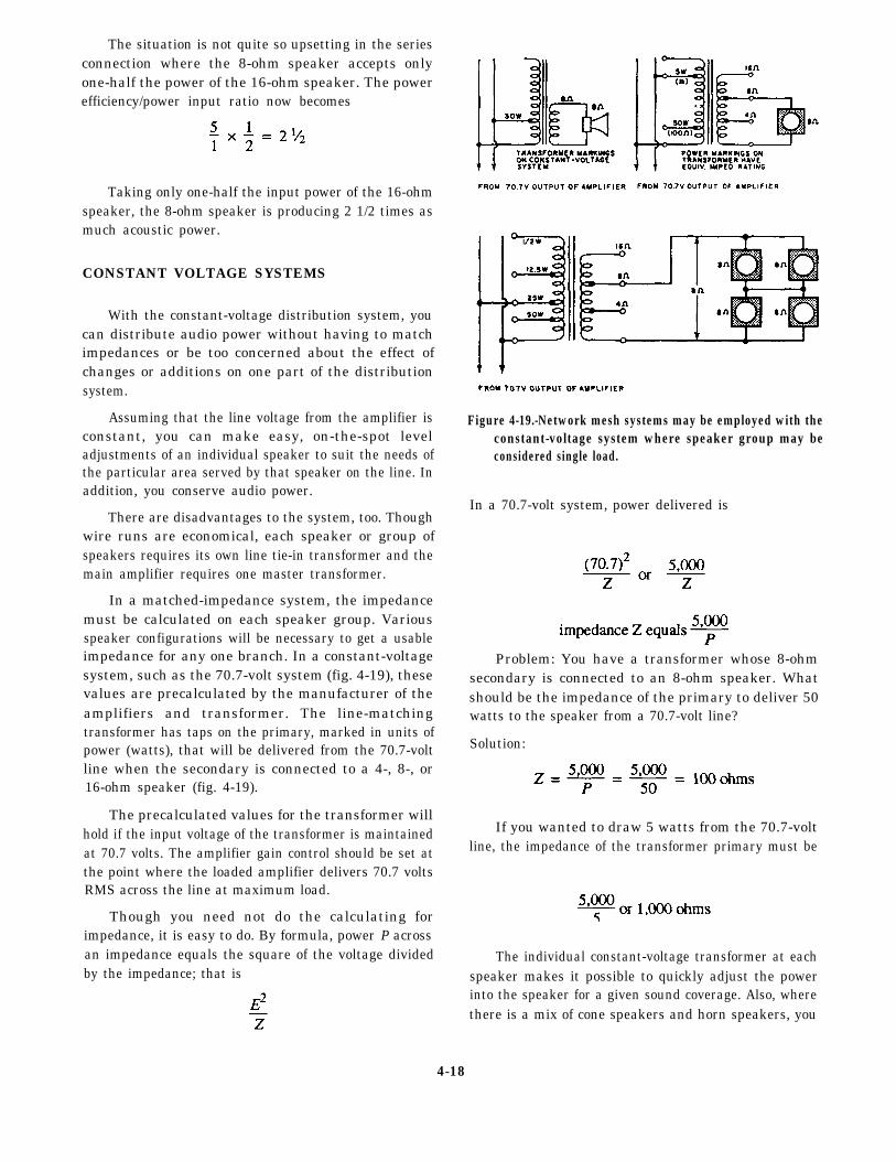
The situation is not quite so upsetting in the seriesconnection where the 8-ohm speaker accepts onlyone-half the power of the 16-ohm speaker. The powerefficiency/power input ratio now becomes
Taking only one-half the input power of the 16-ohmspeaker, the 8-ohm speaker is producing 2 1/2 times asmuch acoustic power.
CONSTANT VOLTAGE SYSTEMS
With the constant-voltage distribution system, youcan distribute audio power without having to matchimpedances or be too concerned about the effect ofchanges or additions on one part of the distributionsystem.
Assuming that the line voltage from the amplifier isconstant, you can make easy, on-the-spot leveladjustments of an individual speaker to suit the needs ofthe particular area served by that speaker on the line. Inaddition, you conserve audio power.
There are disadvantages to the system, too. Thoughwire runs are economical, each speaker or group ofspeakers requires its own line tie-in transformer and themain amplifier requires one master transformer.
In a matched-impedance system, the impedancemust be calculated on each speaker group. Variousspeaker configurations will be necessary to get a usableimpedance for any one branch. In a constant-voltagesystem, such as the 70.7-volt system (fig. 4-19), thesevalues are precalculated by the manufacturer of theamplifiers and transformer. The line-matchingtransformer has taps on the primary, marked in units ofpower (watts), that will be delivered from the 70.7-voltline when the secondary is connected to a 4-, 8-, or16-ohm speaker (fig. 4-19).
The precalculated values for the transformer willhold if the input voltage of the transformer is maintainedat 70.7 volts. The amplifier gain control should be set atthe point where the loaded amplifier delivers 70.7 voltsRMS across the line at maximum load.
Though you need not do the calculating forimpedance, it is easy to do. By formula, power P acrossan impedance equals the square of the voltage dividedby the impedance; that is
Figure 4-19.-Network mesh systems may be employed with theconstant-voltage system where speaker group may beconsidered single load.
In a 70.7-volt system, power delivered is
Problem: You have a transformer whose 8-ohmsecondary is connected to an 8-ohm speaker. Whatshould be the impedance of the primary to deliver 50watts to the speaker from a 70.7-volt line?
Solution:
If you wanted to draw 5 watts from the 70.7-voltline, the impedance of the transformer primary must be
The individual constant-voltage transformer at eachspeaker makes it possible to quickly adjust the powerinto the speaker for a given sound coverage. Also, wherethere is a mix of cone speakers and horn speakers, you
4-18
can compensate quickly for the efficiency of the hornbeing greater than the cone’s (fig. 4-18, view C).Suppose you want to get as much power out of a hornas the cone is delivering, and the cone is tied to the 5-watttap of its transformer. Tying the horn to the 1-watt tapof its transformer would take into account the 5:1efficiency ratio. Now you can make the horn twice asloud as the cone by stepping up its tapped position to the2-watt level.
There is a limit to how many speakers you can tieacross the line in this system, a limit that holds for thetransformerless matched system as well. The total loadon the system by all the speaker transformers and thespeakers should not exceed the total power capacity ofthe amplifier. In the transformer system, you find thelimit by adding the rating capacities of the transformers.In the matched-impedance system, you must measurethe voltage across voltages to power values, then addthem up.
On a constant-voltage line, what do you do with atransformer that is marked in impedance with nomention of power? Using the formula,
convert the primary impedance of the transformer topower. As an example, suppose the transformer has aprimary marked 167 ohms and a secondary marked 8ohms. How much power does this transformer take fromthe 70.7-volt line for its 8-ohm speaker load?
Solution:
MODULAR UNITS
The demand for small, maintainable circuitry inmilitary equipment has led to many differentconstruction techniques. One of the most popular ismodular construction. Since modular assembliesincorporate several subminiaturized features not foundin conventional equipment, some specializedknowledge and tools are required for efficient repair andmaintenance.
MAINTENANCE CONCEPT
A few definitions are helpful in understanding theterms involved. A module is, in the electronic sense, a
packaged functional assembly of wired electroniccomponents for use with other such assemblies. Amodular assembly is constructed with standardizedunits or modules. An equipment that consists ofreplaceable assemblies (any type) is said to be ofunitized construction. Modular construction is a type ofunitized construction that consists of modularassemblies.
For example, think of a carton of cigarettes. If eachpack were a module, the carton would be an equipmentof modular construction. Notice that the packs can bearranged differently without changing the outsidedimensions of the carton. Although the cigarette packsare all the same size, the assemblies in many pieces ofequipment are not.
By their original concept, many modular assemblieswere not to be maintained in the field. The intention wasto replace a faulty assembly and ship it to a repairfacility. As assemblies became more complex, the pointwas reached where the supply system required for thereplacement was too costly. Many of the originalmodules were potted to discourage maintenancepersonnel from tampering with the insides.
When the Navy reassessed this concept and calledfor shipboard maintenance of as much equipment aspossible, most manufacturers began to makecomponents accessible. However, it is difficult to dispelthe conviction that modular assemblies are impossibleto repair. This conviction may stem from a lack ofexperience in working with the printed circuits and theother components in modular assemblies. It is true thatspecial tools and techniques are required. It is also truethat satisfactory repairs can be made to any printedcircuit by using a little care and common sense. With alittle experience, repairs can be made as easily as inconventional assemblies, and often more easily becauseof improved accessibility.
REPAIR OF DEFECTIVE COMPONENTS
One of the time-consuming steps of troubleshootingis the identification of specific components. Inconventionally wired equipment, components are notalways easy to locate. The circuitry in the chassis canbecome confusing since related components are oftenpositioned in different areas of the chassis.
In equipment that includes printed-circuit boards,identification of circuitry and components may berelatively simple. This type of circuit constructionallows uniform placement of components. Just a quick,once-over glance of the circuitry is often all you need to
4-19
see to place the overall layout of the chassis in your mindand to quickly focus your attention on the area ofconcern.
Many commercial manufacturers have developedmethods for quick identification. One of the mostcommon is to impose a grid over a drawing of the boardand a corresponding table that lists the part location.Another technique is to number points of interest on theschematic, then provide a guide to locate the points onthe board.
Circuit tracing of the printed-circuit board maybesimpler than that of conventional wiring, due toincreased uniformity. If the circuit board is translucent,a 60-watt light bulb placed under the side being tracedwill simplify circuit tracing. However, be careful not tooverheat delicate circuit components. In this way, youcan locate test points without viewing both sides of theboard.
Resistance or continuity measurements can be madefrom the component side of the board. In some cases, amagnifying glass will help in locating very small breaksin the wiring. Voltage measurements can be made oneither side of the board. However, a needlepoint probeis needed to penetrate the protective coating on thewiring. You also can locate hairline cracks by makingcontinuity checks.
As a supervisor, you should make sure the people inyour shop or maintenance crews observe the followingprecautions:
– Observe power supply polarities when measuringthe resistance of the circuits containing transistors orother semiconductors. Such parts are polarity andvoltage sensitive. Reversing the plate voltage polarity ofa triode vacuum tube will keep the stage from operating,but generally will not injure the tube. Reversing thevoltage applied to a transistor or other semiconductorwill ruin it very quickly.
CAUTION: Ohmmeter voltage for checkingtransistors and their circuits should be 3 volts or less.
– Make certain power line leakage current is notexcessive before applying ac power-operated testequipment or soldering irons. Use an isolationtransformer with all test equipment and soldering ironsoperated on ac power, unless the equipment contains atransformer in its power supply or shows no leakagecurrent. With all test equipment (whether transformeroperated or not), connect a ground lead from the groundof the circuit to be tested to the test equipment ground.
– Apply a signal from test equipment by startingwith a low output signal setting, then proceeding to therequired signal level. Be sure the signal applied is belowthe rating given for the circuit under test.
– Make sure all parts in a circuit are secure beforestarting to test the circuit or turning on the equipmentpower. Do not cause an inductive kickback or transientcurrent by moving loose connections, disconnectingparts, inserting or removing transistors or similarcomponents, or changing modular units while theequipment power is on or under test.
– Remove all capacitance charges from parts andtest equipment before attaching them to a modularassembly.
SUBSTITUTION OF PARTS
If a specified part cannot be obtained a suitablesubstitute part may be used temporarily, provided thesubstitute is replaced with the specified part as soon asit can be obtained. Make sure the failed part is the sourceof trouble and not the symptom of another failure.
RESISTORS AND CAPACITORS
The use of two or more resistors or capacitors ineither series or parallel combinations to replace aburned-out component is a common practice.
When the proper size resistor or capacitor is notavailable, check your spare parts drawer to see if youcan use what you have on hand in a series or parallelcombination.
Tubes and Transistors
Substitution for defective tubes or transistors isusually an easy task. By consulting the propersubstitution manual, and using the specifications for thetube or transistor you wish to replace, you can normallylocate an acceptable substitute. Be certain to match theminimum specifications for the tube or transistor thatyou are trying to replace.
Relays and Switches
When replacing a relay, switch, or similar controldevice, be sure to consult the proper instruction book orblueprint to check the voltage and current ratings beforeyou start looking for a substitute. When replacing arelay, also consider the resistance of the coil and the typeand arrangement of the contacts. It may also be possibleto make the replacement part yourself or do something
4-20
else that will reduce downtime. Remember, you are onlylooking for a temporary replacement.
SWITCHBOARD MAINTENANCE
Another duty of an IC Electrician is the maintenanceof the power distribution systems assigned to yourdivision. Normally, the required inspections andcleanings are outlined on maintenance requirementcards (MRCs). When the inspection and cleaning is due,you often think only of the main IC switchboard. Thesmall local IC switchboards located in the engineeringspaces and remote sections of the ship are forgotten.Auxiliary IC panels may have their own MRCs. You, asa supervisor, should make sure all power panels receivethe attention needed.
INSPECTION AND CLEANING
At least once a year and during overhaul, eachswitchboard propulsion control cubicle, distributionpanel, and motor controller should be de-energized andtagged out for a complete inspection and cleaning of allbus equipment. Inspection of the de-energizedequipment should not be limited to visual examinationbut should include grasping and shaking electricalconnections and mechanical parts to be certain that allconnections are tight and that mechanical parts are freeto function. Be certain no loose tools or articles are leftin or around switchboards or distribution panels.
Check the supports of bus work to be certain thesupports will prevent contact between bus bars ofopposite polarity or contact between bus bars andgrounded parts during periods of mechanical shock.Clean the bus work and the creepage surfaces ofinsulating material; be certain creepage distances(across which leakage currents can flow) are ample toprevent arcing. Bus bars and insulating materials can becleaned with dry wiping clothes and a vacuum cleaner.Make sure the switchboard or distribution panel iscompletely de-energized and will remain so until thework is completed; avoid cleaning live parts because ofthe danger to personnel and equipment.
The insulated front panels of switchboards can becleaned without de-energizing the switchboard. Thesepanels can usually be cleaned by wiping with a dry cloth.However, a damp, soapy cloth can be used to removegrease and fingerprints. Then wipe the surface with acloth dampened in clear water to remove all soap anddry with a clean, dry cloth. Cleaning cloths must be rungout thoroughly so no water runs down the panel. Cleana small section at a time and then wipe dry.
Rheostats and Resistors
Be certain the ventilation of rheostats and resistorsis not obstructed. Replace broken or burned-outresistors. Temporary repairs of rheostats can be made bybridging burned-out sections when replacements are notavailable. Apply a light coat of petrolatum to thefaceplate contacts of rheostats to reduce friction andwear. Be certain no petrolatum is left in the spacesbetween the contact buttons, as this may cause burningor arcing. Check all electrical connections for tightnessand wiring for frayed or broken leads.
Instruments
The pointer of each switchboard instrument shouldread zero when the instrument is disconnected from thecircuit. The pointer may be brought to zero by externalscrewdriver adjustment.
CAUTION: This should not be done unless properauthorization is given. Repairs to the switchboardinstruments should be made only by the manufacturers,shore-repair activities, or tenders.
Fuses
Be certain fuses are the right size; clips make firmcontact with the times; lock-in devices (if provided) areproperly fitted; and all connections in the wiring to thefuses are tight.
Control Circuits
Control circuits should be checked to ensure circuitcontinuity and proper relay and contactor operation.Because of the numerous types of control circuitsinstalled in naval ships, it is impractical to set up anydefinite operating test procedures in this trainingmanual. In general, certain control circuits, such as thosefor starting motors or motor-generator sets, or voltmeterswitching circuits are best tested by using the circuits asthey are intended to operate under service conditions.
Protective circuits, such as overcurrent, reversepower, or reverse current circuits, usually cannot betested by actual operation because of the dangerinvolved to the equipment. These circuits should bevisually checked and, when possibe, relays should beoperated manually to be certain the rest of the protectivecircuit performs its intended functions. Exerciseextreme care not to disrupt vital power service ordamage electrical equipment. Normally these checksand inspections are outlined on MRCs.
4-21
Bus Transfer Equipment accurate measurements. The secondary should alwaysbe short-circuited when it is not connected to a current
Bus transfer equipment should be tested weekly. Formanual bus transfer equipment, manually transfer a loadfrom one power source to another and check themechanical operation and mechanical interlocks. Forautomatic bus transfer equipment, check the operationwith the control switches. The test should includeoperation initiated by cutting off power (opening anormal feeder circuit breaker) to ascertain if anautomatic transfer occurs. These tests and inspectionsare normally outlined on MRCs.
DIAGNOSTIC MAINTENANCE
When you must perform electrical repair onenergized switchboards, first be sure to obtain theapproval of the commanding officer. Personnel withtelephone headsets should be stationed by circuitbreakers to de-energize the switchboard immediatelyand call for help in case of emergency. The person doingthe work should wear rubber gloves and should not wearloose clothing or metal articles.
Current Transformers
The secondary of a current transformer shouldnever be open while the primary is carrying current.Failure to observe this precaution results in possibledamage to the transformer and the generation of asecondary voltage that may be sufficient magnitude toinjure personnel or damage insulation. A currenttransformer energized with an open-circuited secondarywill overheat due to magnetic saturation of the core.Even though the overheating may have been insufficientto produce permanent damage, the transformer shouldbe carefully demagnetized and recalibrated to ensure
coil.
Potential Transformers
The secondary of a potential transformer shouldnever be short-circuited. The secondary circuit shouldbe completed only through a high resistance, such as avoltmeter or a potential coil circuit, or should be openwhen the primary is energized. A short-circuitedsecondary allows excessive current to flow, which maydamage the transformer.
IC GYRO WATCHSTANDING
As an IC1 or ICC, you will be required to set up andtrain an IC gyro room watch. This training should betailored to the needs of your command with thecommanding officer’s authorization. This trainingshould be documented and conducted according to therequirements of the Standard Organization andRegulations of the U.S. Navy, OPNAVINST 3120.32B.
ENGINEERING OFFICER OF THEWATCH
The engineering officer of the watch (EOOW) is awatch of great importance and responsibilty. We willnot cover it in great depth in this manual because it iscovered by PQS. The EOOW requires qualification inother engineering watch areas before becomingqualified in that watch station. The important thing toremember is that the EOOW is responsible for theproper and safe operation and maintenance of allengineering equipment aboard ship.
4-22
APPENDIX I
GLOSSARY
ALIGNED SECTION– A section view in which someinternal features are revolved into or out of the planeof the view.
APPLICATION BLOCK– A part of a drawing of asubassembly showing the reference number for thedrawing of the assembly or adjacent subassembly.
ARCHITECT’S SCALE– Scale used when dimen-sions or measurements are to be expressed in feetand inches.
AUXILIARY VIEW– An additional plane of an object,drawn as if viewed from a different location. It isused to show features not visible in the normalprojections.
AXONOMETRIC PROJECTION– A set of three ormore views in which the object appears to berotated at an angle, so that more than one side isseen.
BILL OF MATERIAL– A list of standard parts or rawmaterials needed to fabricate an item.
BLOCK DIAGRAM– A diagram in which the majorcomponents of a piece of equipment or a system arerepresented by squares, rectangles, or othergeometric figures, and the normal order ofprogression of a signal or current flow is representedby lines.
BLUEPRINTS– Copies of mechanical or other types oftechnical drawings. Although blueprints used to beblue, modem reproduction techniques now permitprinting of black on white as well as colors.
BODY PLAN– An end view of a ship’s hull, composedof superimposed frame lines.
BREAK LINES– Lines to reduce graphic size of anobject, generally to conserve paper space.
CASUALTY– An event or series of events in progressduring which equipment damage and/or personnelinjury has occurred. The nature and speed of theseevents are such that proper and correct proceduralsteps will only serve toand/or personnel injury.
limit equipment damage
CENTER LINES– Lines that indicate the center of acircle, arc, or any symmetrical object; consist ofalternate long and short dashes evenly spaced.
COMPUTER LOGIC– The electrical processes usedby a computer to perform calculations and otherfunctions.
DIGITAL– The processing of data by numerical ordiscrete units.
DRAWING NUMBER– An identifying numberassigned to a drawing or a series of drawings.
DRAWING– The original graphic design from which ablueprint may be made; also called plans.
ELECTROMECHANICAL DRAWING– A specialtype of drawing combining electrical symbols andmechanical drawing to show the composition ofequipment that combines electrical and mechanicalfeatures.
ELEMENTARY WIRING DIAGRAM– (1) Ashipborad wiring diagram showing how eachindividual conductor is connected within thevarious connection boxes of an electrical circuit orsystem. (2) A schematic diagram; the term issometimes used interchangeably with schematicdiagram, especially a simplified schematic diagram.
EMERGENCY– Event or series of events in progressthat will cause damage to equipment unlessimmediate, timely, and correct procedural steps aretaken.
FAIL POSITION– Operating or physical position towhich a device will go upon loss of its control signal,
FAIL– Loss of control signal or power to a component.Also breakage or breakdown of a component orcomponent part.
FINISH MARKS– Marks used to indicate the degree ofsmoothness of the finish to be achieved on surfacesto be machined.
FORMAT– The general makeup or style of a drawing.
FUNCTION– To perform the normal or characteristicaction of something, or a special duty orperformance required of a person or thing in thecourse of work.
AI-1
INTERCONNECTION DIAGRAM– Diagrams thatshow the cabling between electronic units, as wellas how the terminals are connected.
ISOMETRIC DRAWING– A type of pictorialdrawing. See isometric wiring diagram.
ISOMETRIC WIRING DIAGRAM– A diagramshowing the outline of a ship, an aircraft, or otherstructure, and the location of equipment, such aspanels and connection boxes and cable runs.
LEADER LINES– Thin, unbroken lines used toconnect numbers, references, or notes toappropriate surfaces or lines.
LEGEND– A description of any special or unusualmarks, symbols, or line connections used in thedrawing.
LOGIC DIAGRAM– A type of schematic diagramusing special symbols to show components thatperform a logic or information processing function.
MECHANICAL DRAWING– See drawings. Appliesto scale drawings or mechanical objects.
MIL-STD– Military standards. A formalized set ofstandards for supplies, equipment, and design workpurchased by the United States Armed Forces.
MODULE– Subassemblies mounted in a section.
MONITOR– One of the principal operating modes of adata logger that provides a constant check of plantconditions.
NORMAL MODE– Operating condition at normalahead speeds, differing from maneuvering, wherecertain functions, pumps, or valves are not required,while others are for proper operation of ship andmachinery.
NOTES– Descriptive writing on a drawing to giveverbal instructions or additional information.
OBLIQUE DRAWING– A type of pictorial drawing inwhich one view is an orthographic projection andthe views of the sides have receding lines at anangle.
ONE-LINE SKETCH– Drawing using one line tooutline the general relationship of variouscomponents to each other.
ONE-LINE SCHEMATIC– Drawing of a system usingonly one line to show the tie-in of variouscomponents; for example, the three conductorsneeded to transmit 3-phase power arerepresented by a single line.
PERIPHERAL– Existing on or near the boundary of asurface or area.
PICTORIAL DRAWING– A drawing that gives thereal appearance of an object, showing the generallocation, function, and appearance of parts andassemblies.
PLAN VIEW– A view of an object or area as it wouldappear from directly above.
REFERENCE NUMBERS– Numbers used on onedrawing to refer the reader to another drawing formore detail or other information.
REVISION BLOCK– Located in the upper right cornerof a print. Provides a space to record any changesmade to the original print.
SCALE– The ratio between the measurement used on adrawing and the measurement of the object itrepresents. A measuring device, such as a ruler,having special gradations.
SCALING– Applying a factor of proportionality to dataor signal levels.
SCHEMATIC DIAGRAM– A diagram using graphicsymbols to show how a circuit functions electrically.
SHIP’S PLANS– A set of drawings of all significantconstruction features and equipment of a ship, asneeded to operate and maintain the ship. Also calledonboard plans.
SPAN– Distance between two points.
SPECIFICATION– Detailed d e s c r i p t i o n o ridentification relating to quality, strength, or similarperformance requirement.
STATUS LOG– Record of the instantaneous values ofimportant conditions having analog values.
SYMBOL– Stylized graphical representation ofcommonly used component parts shown in adrawing.
SYSTEM– Major functioned section of an installation.
SYSTEM INTERRELATION– Specific individualoperations in one system affecting the operation inanother system.
TITLE BLOCK– A blocked area in the lower rightcomer of a print. Provides information to identifythe drawing, its subject matter, origins, scale, andother data.
VIEW– A drawing of a side or plane of an object as seenfrom one point.
AI-2

WATCH STATION– Duties, assignments, or WIRING (CONNECTION) DIAGRAM– A diagramresponsibilities that an individual or group of showing the individual connection within a unit andindividuals may be called upon to carry out; not the physical arrangement of the components.necessarily a normally manned position with awatch bill assignment. ZONE NUMBERS– Numbers and letters on the border
of a drawing to provide reference points to aid inindicating or locating specific points on thedrawing.
AI-3

APPENDIX II
REFERENCES USED TO DEVELOP THIS NRTC
Chapter One
Electronics Technician 1 & C, NAVEDTRA 10192-F, Naval Education and TrainingProgram Management Support Activity, Pensacola, Fla., 1987.
Engineering Administration, NAVEDTRA 10858-F1, Naval Education andTraining Program Management Support Activity, Pensacola, Fla., 1988.
IC Electrician 2 & 1, NAVEDTRA 10561-1, Naval Education and Training ProgramManagement Support Activity, Pensacola, Fla., 1988.
Molder 1 & C, NAVEDTRA 10585-C1, Naval Education and Training ProgramManagement Support Activity, Pensacola, Fla., 1987.
Operational Reports, NWP 10-1-10, Chief of Naval Operations, Washington, D.C.,November 1987.
Ships’ Maintenance and Material Management (3-M) Manual, OPNAVINST4790.4B, Chief of Naval Operations, Washington, D.C., August 1987.
Chapter Two
Opticalman 1 & C, NAVEDTRA 12217, Naval Education and Training ProgramManagement Support Activity, Pensacola, Fla., 1991.
Quality Assurance Manual, COMNAVSURFLANTINST 9090.2, CommanderNaval Surface Force United States Atlantic Fleet, Norfolk, Va., November 1985.
Chapter Three
Blueprint Reading and Sketching, NAVEDTRA 10077-F1, Naval Education andTraining Program Management Support Activity, Pensacola, Fla., 1988.
Chapter Four
Blueprint Reading and Sketching, NAVEDTRA 10077-F1, Naval Education andTraining program Management Support Activity, Pensacola, Fla., 1988.
IC Electrician 2 & 1, NAVEDTRA 10561-1, Naval Education and Training ProgramManagement Support Activity, Pensacola, Fla., 1988.
AII-1
NOTE: Although the following references were current when this NRTC was
published, their continued currency cannot be assured. When consulting these
references, keep in mind that they may have been revised to reflect new technology
or revised methods, practices, or procedures; therefore, you need to ensure that
you are studying the latest references.
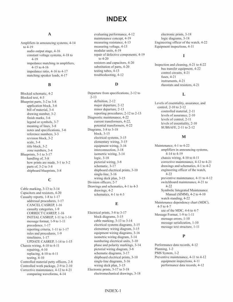
INDEX
A
Amplifiers in announcing systems, 4-14
to 4-19
audio output stage, 4-16
constant voltage systems, 4-18 to
4-19
impedance matching in amplifiers,
4-15 to 4-16
impedance ratio, 4-16 to 4-17
matching speaker loads, 4-17
B
Blocked schematic, 4-2
Blocked text, 4-3
Blueprint parts, 3-2 to 3-8
application block, 3-6
bill of material, 3-4
drawing number, 3-2
finish marks, 3-6
legend or symbols, 3-7
meaning of lines, 3-8
notes and specifications, 3-6
reference numbers, 3-3
revision block, 3-2
scale, 3-4
title block, 3-2
zone numbers, 3-4
Blueprints, 3-1 to 3-17
handling of, 3-8
how prints are made, 3-1 to 3-2
parts of, 3-2 to 3-8
shipboard blueprints, 3-8
C
Cable marking, 3-13 to 3-14
Capacitors and resistors, 4-20
Casualty reports, 1-8 to 1-17
addressal procedures, 1-17
CANCEL CASREP, 1-16
casualty categories, 1-9
CORRECT CASREP, 1-16
INITIAL CASREP, 1-11 to 1-14
message format, 1-9 to 1-11
precedence, 1-17
reporting criteria, 1-11 to 1-17
rules and procedures, 1-9
timeliness, 1-17
UPDATE CASREP, 1-14 to 1-15
Chassis wiring, 4-10 to 4-11
repairing, 4-10
replacing, 4-10 to 4-11
testing, 4-10
Controlled material petty officers, 2-8
Controlled work package, 2-9 to 2-10
Corrective maintenance, 4-12 to 4-21
comparing waveforms, 4-14
evaluating performance, 4-12
maintenance concept, 4-19
measuring resistance, 4-13
measuring voltage, 4-13
modular units, 4-19
repair of defective components, 4-19
to 4-20
resistors and capacitors, 4-20
substitution of parts, 4-20
testing tubes, 4-13
troubleshooting, 4-12
D
Departure from specifications, 2-12 to
2-13
definition, 2-12
major departure, 2-12
minor departure, 2-13
reporting procedures, 2-12 to 2-13
Diagnostic maintenance, 4-22
current transformers, 4-22,
potential transformers, 4-22
Diagrams, 3-8 to 3-18
block, 3-15
electrical systems, 3-15
elementary wiring, 3-15
equipment wiring, 3-16
interconnection, 3-18
isometric wiring, 3-14
logic, 3-18
pictorial wiring, 3-8
schematic, 3-17
shipboard electrical prints, 3-10
single-line, 3-16
wiring deck plan, 3-15
Division officers, 2-7
Drawings and schematics, 4-1 to 4-3
drawings, 4-2
schematics, 4-1 to 4-3
E
Electrical prints, 3-8 to 3-17
block diagrams, 3-15
cable marking, 3-13 to 3-14
electrical systems diagrams, 3-15
elementary wiring diagram, 3-15
equipment wiring diagrams, 3-16
isometric wiring diagram, 3-14
numbering electrical units, 3-10
phase and polarity markings, 3-14
pictorial wiring diagram, 3-8
schematic diagrams, 3-17
shipboard electrical prints, 3-10
single-line diagrams, 3-16
wiring deck plan, 3-15
Electronic prints, 3-17 to 3-18
electromechanical drawings, 3-18
electronic prints, 3-18
logic diagrams, 3-18
Engineering officer of the watch, 4-22
Equipment inspections, 4-11
I
Inspection and cleaning, 4-21 to 4-22
bus transfer equipment, 4-22
control circuits, 4-21
fuses, 4-21
instruments, 4-21
rheostats and resistors, 4-21
L
Levels of essentiality, assurance, and
control, 2-10 to 2-12
controlled material, 2-11
levels of assurance, 2-10
levels of control, 2-11
levels of essentiality, 2-10
SUBSAFE, 2-11 to 2-12
M
Maintenance, 4-1 to 4-22
amplifiers in announcing systems,
4-14 to 4-19
chassis wiring, 4-10 to 4-11
corrective maintenance, 4-12 to 4-21
drawings and schematics, 4-1 to 4-2
engineering officer of the watch,
4-22
preventive maintenance, 4-11 to 4-12
switchboard maintenance, 4-21 to
4-22
Symbolic Integrated Maintenance
Manual (SIMM), 4-2 to 4-10
watch standing, 4-22
Maintenance dependency chart (MDC),
4-5 to 4-7
use of the MDC, 4-6 to 4-7
Message Format, 1-9 to 1-11
message errors, 1-10
message serialization, 1-10
message text structure, 1-11
P
Performance data records, 4-12
Planning, 1-2
PMS System, 1-2
Preventive maintenance, 4-11 to 4-12
equipment inspections, 4-11
performance data records, 4-12
INDEX-1

Q
QA forms and records, 2-13 to 2-25
QA Form 1, Material Receipt
Control Record, 2-13
QA Form 2, Material In-Process
Control Tag, 2-13
QA Form 3, Controlled Material
Reject Tag, 2-13
QA Form 4, Controlled Material
Ship-to-Shop Tag, 2-13
QA Form 4A, Ship-to-Shop Tag
(General Use), 2-13
QA Form 7, Controlled Material
Inventory/Record, 2-16
QA Form 8, Production Task Control
Form, 2-16
QA Form 8A, Material Requirements
(Controlled
Work Package Only), 2-16
QA Form 9, Re-entry Control Form,
2-17
QA Form 9A, Re-entry Control
Supplement Sheet, 2-17
QA Form 10, Re-entry Control Log,
2-17
QA Form 12, Departure from
Specification Report, 2-13
QA Form 13, Quality Assurance
Information Sheet, 2-17
QA Form 15, Request for Release of
Rejected Material or Workman-
ship, 2-17
QA Form 16, Material Deficiency
Report, 2-22
QA Form 17, Test and Inspection
Form-other than NDT, 2-22
Quality assurance, 2-1 to 2-25
controlled work package, 2-9 to 2-10
departure from specifications, 2-12
to 2-13
levels of essentiality, assurance, and
control, 2-10 to 2-12
QA forms and records, 2-13 to 2-25
quality assurance organization, 2-3 to
2-4
quality assurance program, 2-1 to 2-3
quality assurance requirements,
training, and
qualification, 2-6 to 2-8
quality assurance terms and
definitions, 2-8 to 2-9
responsibilities for quality of
maintenance, 2-5 to 2-6
Quality assurance officer, 2-4 to 2-7
Quality assurance organization, 2-3 to 2-4
Quality Assurance Program, 2-1 to 2-3
concept of quality assurance, 2-2
goals, 2-3
operation of, 2-8
program components, 2-2
quality assurance link to
maintenance, 2-3
Quality assurance requirements, training,
and qualification, 2-6 to 2-8
Quality assurance supervisors, 2-7
Quarterly reports, 1-8
R
Repair officer, 2-7
Reports, 1-8 to 1-19
casualty reports, 1-8 to 1-17
quarterly reports, 1-8
situation reports, 1-18 to 1-19
Resistors and capacitors, 4-20
S
Scales, 3-4
architects’, 3-4
engineers’, 3-4
graphic, 3-4
metric, 3-4
Scheduling of work, 1-3 to 1-6
Schematics, 4-1 to 4-3
blocked schematic, 4-2 to 4-3
Ship quality control inspectors, 2-4 to 2-6
Ships’ drawings and diagrams, 3-1 to
3-18
blueprints, 3-1 to 3-8
electrical prints, 3-8 to 3-17
electronic prints, 3-17 to 3-18
Shop supervision, 1-1 to 1-8
estimating work 1-6 to 1-7
information on incoming work 1-3
maintenance and repair, 1-1
materials and repair parts, 1-7 to 1-8
planning, 1-2
priority of jobs, 1-3
scheduling of work, 1-3 to 1-6
Situation reports, 1-18 to 1-19
Submarine Safety Program (SUBSAFE),
2-11 to 2-12
Switchboard maintenance, 4-21 to 4-22
diagnostic maintenance, 4-22
inspection and cleaning, 4-21
Symbolic Integrated Maintenance Manual
(SIMM), 4-2 to 4-10
alignment procedures, 4-7
blocked schematic, 4-2 to 4-3
blocked text, 4-3 to 4-4
improvements, 4-9 to 4-10
indexing of related information, 4-7
maintenance dependency chart, 4-5
to 4-7
operating procedures, 4-5
parts location and identification, 4-9
precise-access blocked diagram, 4-4
to 4-5
repair of mechanical assembly, 4-9
T
Technical administration, 1-1 to 1-19
preparation of reports, 1-8 to 1-19
shop supervision, 1-1
Troubleshooting, 4-12
W
Watch standing, 4-22
Wiring chassis, 4-10 to 4-11
INDEX-2
ASSIGNMENT 1
Textbook Assignment: “Technical Administration,” and “Quality Assurance,” chapters 1 and2, pages 1-1 through 2-5.
1-1. The shop supervisor is responsiblefor checking and inspectingcompleted repairs.
1 . T r u e2. False
1-2. You can ensure proper personnelemployment by the use of which ofthe
1.2.3.4 .
following documents?
Quarterly scheduleCycle scheduleWeekly work scheduleMRC (job card)
1 -3 . Which of the following statementsis true concerning an MRC (jobc a r d ) ?
1. Cards are made out for astandard system and cannot bemodified
2. Card job procedures are not inany sequential order
3. Cards can only be used oncerta in ships
4 . Cards should be tailored foruse on your ship through theuse of the PMS feedback report
1 -4 . What person must give permissionfor emergency repairs?
1. The execut ive o f f i cer2. The o f f i cer o f the deck3 . T h e d i v i s i o n o f f i c e r4 . The chief engineer
1-5. When a job is received by a repairfacility, when should the planningcommence?
1. As soon as possible2. When the job is started3. One week after receipt of the
j o b4 . The same day the job is
rece ived
1-6 . Except when dealing with a sincerepersonal problem, what is thecorrect procedure to use when youmust talk with one of a subgroupsuperv isor ’ s subordinates?
1. Talk to the person alone2. Talk to the subgroup
supervisor; then talk to theperson
3. Have the subgroup supervisoraccompany the person
4 . Talk to the person alone; thentalk to the subgroup supervisor
1 -7 . Which of the following is thecorrect pr ior i ty for p lanning andscheduling work?
1. Rout ine , de ferred , urgent2. Urgent , rout ine , de ferred3 . Urgent , de ferred , rout ine4 . Rout ine , urgent , de ferred
1-8 . Which of the following informationshould be considered in determiningthe
1.
2 .
3.
4 .
p r i o r i t y o f a t a s k ( j o b ) ?
The ship’s schedule and theeffect the equipment will haveon the ab i l i ty o f the sh ip toperform its missionWhether the work requiressomeone with special skillsWhether or not all the requiredparts and materials area v a i l a b l eAll of the above
1-9 . What OPNAV form is used to defer amaintenance action?
1. 4790/2K2. 4790/2R3. 4790/P14 . 4790/2L
1
1-10. What is the advantage of assigninga d i f f i cu l t or complex job to aless experienced person workingunder close supervision instead ofto a more experienced person?
1. You can assign a low priorityto the j ob
2. You will give the lessexperienced person a chance togain experience in such tasks
3. You will not have to furnish adrawing or general statementabout the job
4 . You will not have to inspectthe job a f ter i t i s completed
1-11. Which of the following factorsshould you consider when planning ashipboard maintenance action orrepair work?
1. S ize o f the j ob2. Material needed and what
mater ia l i s avai lab le3 . Pr ior i ty o f the job4 . Each of the above
1-12. The work center supervisor shouldreview the week’s work with whichof the following personnel todetermine which jobs need to bedone right away?
1. The d iv is ion o f f i cer2. The chief engineer3. The execut ive o f f i cer4 . The commanding officer
1-13. Which of the following is one ofthe main purposes for inspecting aj o b a f t e r i t i s f i n i s h e d ?
1. To sign off the job order2. To evaluate the worker’s skills
and knowledge3. To evaluate the priority
assigned to the job4 . To estimate the man-hours for
the job
1-14. In estimating time to complete atask, which of the followingfactors is NOT your responsibility?
1. Time for another shop to do itsj o b
2. Time to be spent in othera c t i v i t i e s , s u c h a s d r i l l s
3. Rate at which personnel can dothe work
4 . Pr ior i ty o f the var ious jobsassigned to your shop
1-15. The number of individuals who canwork effectively on a job at thesame time is an important factorwhen making which of the followingestimates?
1. The amount of material thatwill be wasted on the job
2. The kind of materials the jobrequires
3. The time it takes to complete aj o b
4 . The time that will be lost todr i l l s , inspect ions , and workp a r t i e s
1-16. When work is sent to an outsideactivity, what OPNAV form shouldyou use?
1. 4790/2Q2. 4790/2K3. 4790/2R4. 4790/2L
1-17. Estimating the materials requiredfor a cer ta in repair j ob i s o f tenmore difficult than estimating thetime and labor required for thej o b .
1. True2. False
2
1-18. Which of the following is a goodway to get a handle on what ishappening during each step of ajob?
1. Ask the commanding officer2 . Quest ion the ch ie f engineer3. Talk to the command master
c h i e f4. Consult the ship’s master
training schedule and monthlytra in ing p lan
1-19. Which of the following documentsare NOT useful in planning a job?
1. Rate training manuals2. Ship’s drawings3. Bluepr ints4. Manufacturers’ technical
manuals
1-20. Which of the following is NOT aduty o f supply o f f i cers?
1. Buy material2. Stow material3 . Make out the abandon ship bill4 . Account for most types of
s t o r e s
1-21. Which of the following informationwill you NOT likely find on thenameplate of a piece of equipment?
1. Serial number, stock number,and model number
2. Operating values, such asvo l ts , current , and speed
3. Manufacturer’s name4. Materials required for repairs
1-22. To locate repair materials notspec i f ied in the instruct ionsaccompanying a job, which of thefo l lowing i s /are exce l lent sourcesto use?
1. Ships ’ p lans , b luepr ints , anddrawings
2. Engineering log book3. Engineer’s bell book4 . Gyro maintenance log
1-23. All materials in the supply systemare assigned which of the followingnumbers?
1. Part number2. Job sequence number3. Stock number4. Social security number
1-24. The administration and supervisionof maintenance and repair of thegyrocompass is the responsibilityof which of the followingpersonnel?
1. Gyro technician2. Gyro shop personnel3. Commanding officer4 . Gyro o f f i cer
1-25. After a casualty occurs, a CASREPshould be submitted within whatmaximum period of time?
1. 12 hr2. 18 hr3. 24 hr4 . 48 hr
1-26. Once a casualty is reported, whatperson /o f f i ce should rece ive hardcopies of CASREP messages?
1. CNO, fleet commanders, andship ’ s parts contro l center
2. CNO, squadron commanders, andcommanding officer
3. CNO, fleet commanders, andcommanding officer
4 . Commanding officer, squadroncommanders, and ship’s partscontro l center
1-27. What is the maximum number ofcasualty categories used by allcommands except for NAVEDTRACOMs?
1. Five2 . T w o3. Three4 . Four
3
1-28. An UPDATE CASREP containsinformation similar to thatsubmitted in which of the followingdocuments?
1. CASCOR2. CASCAAN3. SITREP4. INITIAL CASREP
1-29. What type of CASREP identifies thestatus of the casualty and partsand/or assistance requirements?
1. UPDATE2. INITIAL3. CANCEL4. CORRECT
1-30. A CORRECT CASREP should besubmitted in which of the followings i t u a t i o n s ?
1. When the causalty has beenc o r r e c t e d
2. Within 24 hours of discovery ofa casualty
3. When a casualty is over 48hours old
4. When there is more informationto report than originally known
1-31. What total number of casualtycategories do NAVEDTRACOMa c t i v i t i e s u s e ?
1. S i x2. Five3. Three4 . Four
1-32. For additional information on theStatus of Resources and TrainingSystem (SORTS), you should refer towhat chapters of NWP 10-1-10?
1. 3 and 42. 1 and 43. 1 and 54. 5 and 6
1-33. The casualty category is NOTrequired in the casualty set in allCASREPs.
1. True2. False
1-34.
1-35.
1-36.
1-37.
1-38.
The dec is ion log ic t ree i s used forwhich of the following purposes?
1. To determine the unit ’s overalls tatus category
2. To determine the M-rating3. To determine the casualty
category and whether or not acasual ty i s required
4 . Each of the above
The serialization for a CASREP willappear in which, if any, of thefo l lowing p laces?
1. After the messagec l a s s i f i c a t i o n l i n e
2. Before the messagec l a s s i f i c a t i o n l i n e
3. In the message c lass i f i cat ionl i n e
4 . None of the above
Which of the following statementsis true concerning the serialnumbers for CASREPs?
1. They are in nonsequential order2. They are sequential from 1
through 993. New sequence numbers start
after submission of number 994 . They are sequential from 1
through 999
CASREP messages transmitted witherrors can only be corrected withwhat document?
1. CORRECT CASREP2. CANCEL CASREP3. UPDATE CASREP4. Routine message
How many different types of datasets are used in CASREP messages?
1. One2 . T w o3. Three4. Four
4
1-39. What casualty set is used to reportwhether or not a unit requiresoutside assistance to repair anequipment casualty?
1. 1PARTS2. 1STRIP3 . ASSIST4 . A M P N
1-40. When a unit requires assistanceand/or parts to repair a casualty,schedule information must bereported in the RMKS set for whatspec i f i c per iod o f t ime?
1. 7 days2 . 14 days3. 20 days4 . 30 days
1-41. What total number of casualties canbe updated per UPDATE CASREPmessage?
1. One2 . T w o3. Three4 . Four
1-42. When must a unit submit a CANCELCASREP?
1. When additional malfunctionsare discovered
2. When equipment that has beenthe subject of a CASREP isscheduled to be repaired duringan overhaul period
3. When parts are received4 . When there is a need to
complete information reportingrequirements
1-43. CASREP messages must be assignedthe highest precedence consistentwith the importance of the types ofreport , the locat ion , and thet a c t i c a l s i t u a t i o n .
1. True2. False
1-44. What are situation reports(SITREPs)?
1. Reports required to reportoutstanding casual t ies
2. Reports required when there isa need to revise previouslysubmitted information
3. One-time reports required whencerta in s i tuat ions ar ise
4 . Reports that allow operationaland s ta f f author i t ies torequest necessary resources
1-45. Which of the following programsprovides maintenance personnel withinformation and guidance necessaryto administer a uniform policy ofmaintenance and repair?
1. 3-M2. QA3. IEM4. COSAL
1-46. The achievement of an effective QAprogram depends on which of thefo l lowing factors?
1. Speed o f repa ir , spec ia lskills, and knowledge
2. Speed o f repa ir , spec ia lsk i l l s , and prevent ion o fmaintenance problems
3. Knowledge, prevention ofmaintenance problems, and speedo f r e p a i r s
4 . Knowledge, prevention ofmaintenance problems, ands p e c i a l s k i l l s
1-47. What number is asigned to the SQCIby the QAO for use on all forms andtags that require in i t ia ls as proo fthat cert i f i ed tests andinspections were completed?
1. Social security number2. Stock number3. Personal serial number4 . Personal pin number
5
1-48. The QA manual for each TYCOM setsforth which of the followingrequirements?
1. Maximum QA requirements2. Minimum QA requirements3. Specific QA requirements for
ships4. Specific QA requirements for
shore
1-49. The instructions contained in theQA manual apply to whatorganizat ions?
1. Shore act iv i t ies only2. Combat ships only3. Repair ships only4. Every ship and activity of the
f o r c e
1-50. If conflicts exist between the QAmanual and previously issuedletters and transmittals byappropriate force commanders, theletters and transmittals takeprecedence.
1. True2. False
1-51. Which of the following isconsidered part of job execution?
1. Completing QA forms2. Meeting controlled material
requirements3. Training personnel4 . Auditing programs
1-52. The administrative part of the QAprogram consists of which of thefo l lowing parts?
1. Preparing work procedures2. Requisitioning material3. Monitoring programs4. Test ing and recert i fy ing
1-53. Technica l spec i f i cat ions can beruled out in the interest ofcompleting the job quickly.
1-54. Which of the following factorsspawned the need for thedevelopment of the QA program?
1. The ever-increasing technicalcomplexity of present-daysurface ships and submarines
2. The ever-increasing workload ofthe work centers aboard ship
3. The ever-increasing lack offormal tra in ing for technic iansaboard ship
4 . Each of the above
1-55. A certa in leve l o f conf idencerequired in the re l iab i l i ty o frepairs made is known as what typeo f l e v e l ?
1. Level of assurance2. Leve l o f contro l3. L e v e l o f e s s e n t i a l i t y4 . L e v e l o f r e l i a b i l i t y
1-56. Which of the following is one ofthe main goals of the QA program?
1. To ensure every repair of anyfailed equipment is documented
2. To decrease the time betweenequipment failure
3. To ensure the safety ofpersonnel while working onSUBSAFE items
4 . To protect personnel fromhazardous conditions
1-57. What is the most difficult part ofplanning a job?
1. Determining which technicalspec i f i cat ion sources areappl i cab le to a part i cu lar j ob
2. Determining the number ofpersonnel required toaccompl ish a spec i f i c j ob
3. Determining what material isneeded
4. Determining how much time isrequired to accomplish the job
1. True2. False
6
1-58. What person is responsible formaintaining the ship’s QA recordsand test and inspection reports?
1. The type commander2. The commanding officer3. The repair o f f i cer4. The qual i ty assurance o f f i cer
1-59. The QA program (Navy) begins withwhich of the following personnel?
1. The commanding officer of theship
2. The type commander3. The qual i ty assurance o f f i cer4 . The commanders in chief of the
f l e e t
1-60. What person is responsible to theforce commander for QA in themaintenance and repair of the ship?
1. The type commander2. The commanding officer3. The qual i ty assurance o f f i cer4 . The ship quality control
inspector
1-61. What person(s) provide(s)instruct ion , po l i cy , and overal ldirection for implementation andoperation of the force QA program?
1. The commanders in chief of thef l e e t
2. The type commanders3. The commanding officer4 . The qual i ty assurance o f f i cer
1-62. Which of the following personnel isrespons ib le for in i t iat ing adeparture f rom spec i f i cat ionreport?
1. The work center supervisor2. The qual i ty contro l inspector3. The person finding or causing
the departure4. The qual i ty assurance o f f i cer
1-63. The qual i ty assurance o f f i cer i sresponsible to the commandingof f i cer for which o f the fo l lowingtasks?
1. Coordinating the ship’s 3-Mt r a i n i n g
2. Conducting the ship’s QAt r a i n i n g
3 . Reviewing procedures and workpackages prepared by the shipbefore submission to theengineer
4 . Reviewing personnel records toensure that everyone isqualified as quality assuranceinspectors
1-64. The SQCI is responsible for whichof the fo l lowing act ions?
1. Planning work for the workc e n t e r
2. Scheduling preventivemaintenance
3. Assigning work to maintenancepersonnel
4 . Inspecting all work forconformance to spec i f i cat ions
1-65. Which of the following personnelmust know the specifications limitsof a job and the purpose of thesel i m i t s ?
1. Execut ive o f f i cer on ly2. Leading pet ty o f f i cer on ly3. Chie f pet ty o f f i cer on ly4 . Each person involved in the job
1-66. Any technical or administratived irect ive that de f ines repaircriteria is known as a/an
1. c a l i b r a t i o n2. acceptance3. s p e c i f i c a t i o n4 . inspect ion record
1-67. What term is defined as a writteninstruction designed to produceacceptable and reliable products,whether produced or repaired?
1. Inspect ion2. Procedure3 . Process4 . SUBSAFE
7
1-68. The e f fec t ive operat ion o f asuccessful QA program requires thee f for t o f which o f the fo l l owingpersonnel?
1. Commanding officer only2. Quality assurance officer only3. Engineer ing o f f i cer on ly4 . All hands
1-69. The person with the most directconcern for quality workmanshipwithin a work center is which ofthe following personnel?
1. The production supervisor2 . The shop craftsmen3. T h e d i v i s i o n o f f i c e r4 . The department head
1-70. Which of the following is anexample of a QA action performedfollowing the completion of aser ies o f tasks?
1. Final inspect ion2. In-process inspect ion3. Rece iv ing inspect ion4 . Screening inspection
1-71. What type of inspection determinesthe condi t ion o f mater ia l ,maintenance requirements, anddispos i t ion and correctness o faccompanying records and documents?
1. Final inspect ion2. Midterm inspection3. In-process inspect ion4 . Receiving or screening
inspect ion
1-72. Which of the following actions isNOT considered to be part of thein-process inspect ion?
1. A per iod ic or spec ia leva luat ion o f deta i l s , p lans ,po l i c ies , procedures , productd irect ives , and records
2. The witnessing of taskperformance
3. The application of torque andfunct ional test ing
4 . Adjusting, assembling,serv ic ing , and insta l lat ion
1-73. What person is responsible forcoordinating and administering theQA program within a work center?
1. SQCI2 . Q A O3. Work center supervisor4 . D i v i s i o n o f f i c e r
8
ASSIGNMENT 2
Textbook Assignment: “Quality Assurance (continued),” and “Ship’s Drawings and Diagrams,”chapters 2 and 3, pages 2-6 through 3-18.
2 -1 . Which of the following is NOT aresponsibil ity of the SQCI?
1. Developing a thoroughunderstanding of the QA program
2. Assigning jobs that require awork package
3. Maintaining records and fi lesto support the QA program
4 . Ensuring that all work centerpersonnel are familiar withapplicable QA manuals byconduct ing tra ining
2-2 . What term describes a managementfunction that attempts to eliminatedefec t ive products?
1 . Qual i ty assurance2 . Q u a l i t y c o n t r o l3. A u d i t4 . Controlled material
2 -3 . Which of the following personnelis /are respons ib le for conduct inginternal audits as required andtaking corrective action on noteddiscrepanc ies?
1. D i v i s i o n o f f i c e r2. Quality assurance officer3. SQCI4 . All of the above
2-4 . Which of the following personnel isrespons ib le for inspect ing ,segregating, stowing, and issuingcontro l led mater ia l?
1 . C M P O2. S Q C I3. D i v i s i o n o f f i c e r4 . Work center supervisor
2 -5 . What QA function is performed toidentify production standards ormater ia l character is t i cs dur ingmanufacture or a repair cycle thatmay not be detectable during finalinspect ion?
1. Quality assurance2. Qual i ty contro l3. In -process inspect ion4 . Technica l repair
s tandardizat ion
2-6 . Alternate SQCIs (backup personnel)do not need to have the same degreeo f qual i f i cat ions and wi l l not begiven the same responsibil ities asnormally assigned SQCIs.
1. True2. False
2 -7 . CMPOs are trained and qualified bythe QA supervisor and are normallyof what paygrade(s)?
1. E3 and E42. E4 only3. E5 only4 . E4 and E5
2-8 . The commanding officer assigns theprimary duty of which of thefollowing personnel in writingaccording to the QA manual?
1. SQCI2. QAO3. CMPO4. PAO
2-9 . What person is responsible fortraining and qualifying the workcenter SQCI?
1. Quality assurance officer2. D i v i s i o n o f f i c e r3. Ship qual i ty contro l inspector4. Quality assurance supervisor
9
2-10.
2-11.
2-12.
2-13.
Which of the following personnelis/are given a written examinationas well as an interview beforebecoming qualified to do theassigned job?
1 . Q A O2. CMPO only3. SQCI only4 . CMPO and SQCI
In addition to a good personnelorientation program, which of thefollowing elements are required foran effective QA program?
1. A comprehensive trainingprogram, use of proper repairprocedures, and a uniforml i b e r t y p o l i c y
2 . A comprehensive trainingprogram, use of proper repairprocedures, and uniforminspection procedures
3. Use of proper repairprocedures, use of new toolsand equipment, and uniforminspection procedures
4. Use of new tools and equipment,proper working environment, anduni form l iberty po l i cy
What number provides traceabilityfrom the work package to othercert i f i cat ion documentat ion?
1. Job control number2. Identification number3. Serial number4 . Stock number
What term best describes when anauthorized representative approvesspec i f i c serv ices rendered?
1. Quality control2. Inspect ion3. Acceptance4 . Inspect ion record
2-14. The examination and listing ofcomponents and services todetermine whether they conform tospecified requirements is definedby what term?
1. Acceptance2 . Inspect ion3 . In-process inspect ion4. Cal ibrat ion
2-15. I f , dur ing the repair process , youmust change the original scope ofthe work to be performed, whatprocedure must you initiate?
1. Rev is ion2. Addendum3. Automated work request4 . Controlled work package
2-16. Which of the following informationis NOT provided to a supervisor ina CWP?
1. QA form instructions2. QC procedures3. QC techniques4 . Stowage location of SUBSAFE
mater ia l
2-17. What procedure should you followi f , dur ing a repair processinvolving simultaneous performanceof procedure steps, the steps arei n d i f f e r e n t l o c a t i o n s ?
1. Reject the job and send the (CWPback to planning
2. Make a copy of the CWP with itsdocumentation for each job site
3. Use locally developed practices4 . Have the CWP at one job site
o n l y
2-18. What term describes thedocumentation contained inside aCWP?
1. Rev is ion2 . Enclosures3 . Addendum4 . S p e c i f i c a t i o n s
10
2-19. What term indicates the impact thatcatastrophic fa i lure o f theassociated part or equipment wouldhave on the ship’s missioncapability and personnel safety?
1. Levels of assurance2. L e v e l s o f e s s e n t i a l i t y3. Leve ls o f necess i ty4 . Leve ls o f contro ls
2-20. Which , i f any , o f the fo l lowinglevels of assurance normallyrequires both quality control andtests and/or inspection methods?
1. A2. B3. C4 . None of the above
2-21. What level of assurance providesfor “as necessary” ver i f i cat iontechniques?
1 . A2. B3. C4. I
2-22. Which of the following is NOT adescr ipt ion o f contro l led mater ia l?
1. It has special markings2. I t has accountabi l i ty
throughout the repair ormanufacturing process
3. It is stowed separately4 . It must be open purchased
2-23. What term is defined as the degreesof control measures required toassure re l iab i l i ty o f repairs madeto a system, subsystem, orcomponent?
1. In -process inspect ion2. Levels of assurance3. Leve ls o f contro l4 . L e v e l s o f e s s e n t i a l i t y
2-24. What person must inspect controlledmater ia l for required at tr ibutesbefore it can be used in a systemor component?
1. QAO2. SQCI3. CMPO4 . DCPO
2-25. SUBSAFE requirements are split intowhat total number of categories?
1. Five2 . T w o3. Three4 . Four
2-26. What term is defined as anysubmarine system determined byNAVSEA to require the specialmater ia l or operabi l i tyrequirements of the SUBSAFEprogram?
1. SUBSAFE boundary2 . SUBSAFE barrier3 . SUBSAFE material4 . SUBSAFE system
2-27 . What term is defined as the recordo f ob jec t ive ev idence estab l i sh ingthe requis i te qual i ty o f thematerial, component, or work done?
1. Procedure2. Documentation3. Controlled work package4 . Departure from specification
2-28 . Which of the following problems maycause a worker to fail to report adeparture f rom spec i f i cat ion?
1. Lack of training2. Lack of time for adequate
planning3. Lack of adequate inspection4. Each of the above
11
2-29.
2-30.
2-31.
2-32.
2-33.
When there is a lack of compliancewith cognizant technical documents,drawings, or work procedures duringa maintenance action that will notbe corrected before the ship getsunderway, what document isrequired?
1. OPNAV Form 4790/22. OPNAV Form 4790/213 . ACN4. Departure from specification
What type of departure fromspecification must be approved bythe appropriate authority?
1. Major only2. Minor only3 . Semiminor only4. Any departure from
s p e c i f i c a t i o n
What are the two types of departurefrom spec i f i cat ions?
1. Major and minor2 . Major and semiminor3. Minor and semiminor4. Semiminor and minimal
What person is responsible forreporting a departure froms p e c i f i c a t i o n ?
1. SQCI2. CMPO3. QAO4. The person who discovered or
caused the departure
Which of the following terms isdefined as a set of actions writtenin a special sequential order bywhich maintenance action, a test,or an inspection is done usings p e c i f i c g u i d e l i n e s , t o o l s , a n dequipment?
1. Process2. Procedure3. Documentation4. Audit
2-34.
2-35.
2-36.
2-37.
2 -38 .
What QA form lists all tests andi n s p e c t i o n s t h a t m u s t b eat each step?
1. 122. 133. 164. 17
What QA form is attached by supplyQA, or shop personnel to providetraceability of accepted controlledmaterial from receipt inspectionthrough f inal inspect ion?
1. 72. 23. 34. 4A
What QA form is used by the CMPO toprovide a standard inventory recordof controlled material received andissued?
1. 72. 83. 8A4. 9
What QA form is used to identifyand control material and equipmentin a positive manner from ship torepair shop?
1. 92. 9A3. 4A4. 4
Which of the following arereproduced copies of mechanical orother types of technical drawings?
1. E l e c t r i c a l p r i n t s2. Electronic pr ints3. Blueprints4 . Electromechanical drawings
12
2-39. What is the meaning of the term“bluepr int reading”?
1. Reading aloud the printedmatter in the legends
2 . Giv ing ora l d i rect ions to theoperator of the machinereproducing the blueprint
3 . Interpreting the ideasexpressed on drawings
4 . Reading related matter to helpyou understand the blueprintsymbols
2-40. Which of the following printingprocesses produces prints withblack, blue, or maroon lines on awhite background?
1. VanDyke printing2. Ozal id pr int ing3. Black-and-white printing4 . Mimeograph printing
2-41. Which of the following processesmay be used for reproducing smalldrawings or sketches?
1. Mimeographing2. D i t t o i n g3. Photostat ing4 . Each of the above
2-42. Blueprints are printed directly onsensitized paper from which of thefo l lowing sources?
1. A drawing or tracing ontranslucent paper or cloth
2. An original drawing on a steelp l a t e
3. A photographic negative of adrawing
4 . A drawing copied onto a clearg lass sheet
2-43. Which of the following referencesgives the l ist of graphic symbolsf o r e l e c t r i c a l a n d e l e c t r o n i cdiagrams?
2-44.
2-45.
2 -46 .
2-47.
2-48.
In which corner of a blueprint isthe t i t le b lock located?
1. Upper right2 . Lower le f t3. Upper left4 . Lower right
In which comer of a blueprint isthe revision block usually found?
1. Lower right2. Lower left3. Upper right4 . Upper left
If a blueprint bearing the drawingnumber 5123476-C is revised, whatwill be the revised drawing numbero f the rev ised pr int?
1. 5123476-C12 . 5123476-D3. 5123476-1C4. 1-5123476
I f the actual l ength o f an ob jec tis 5 inches, what is the length ofits drawing on a blueprint with ascale of 2” = 1”?
1. 1 /2 in .2. 2 1/2 in.3. 5 i n .4. 10 i n .
What number on a blueprint servesthe same purpose as numbers andletters printed on the borders ofmaps?
1. Zone2. Reference3. Scale4 . Drawing
1. MIL-STD-100E2. MIL-STD-15 (Part No. 2)3. ANSI Y32.24 . ANSI Y39.2
13
2-49. Although the scale of a blueprintindicates the dimensions of thedrawing relative to the actual sizeof the object, you should notmeasure the drawing to determinethe actual s ize o f the ob jec tbecause of which of the followingreasons?
1. You must verify the accuracy ofthe sca le
2. You must verify the accuracy ofthe b luepr int
3. You must avoid errors madebecause o f incorrectinterpretat ion o f the sca le
4 . You must avoid any errors madein the original drawing
2-50 . Which scale is divided into decimalgraduations?
1. Graphic2. Engineers ’3. Metr i c4 . A r c h i t e c t s ’
2-51. Which scale indicates the number offeet or miles represented by aninch?
1. A r c h i t e c t s ’2. Engineers’3. Graphic4. Metric
2-52. Which block of a blueprint l iststhe parts and materials used on orrequired by the print concerned?
1. Appl i cat ion2 . T i t l e3. Notes and Specifications4 . Bi l l o f mater ia l
2-53. What information appears in theUsed On column of a blueprint’sappl i cat ion b lock?
1. Model number or equivalentdesignation of the assembledunit of which the part is acomponent
2. Drawing or model number of thenext larger assembly to whichthe drawing applies
3. Authentication for thebluepr int
4 . Second part of a two-detailb luepr int
2-54. In which comer of a blueprint isthe legend of symbols located?
1. Upper right2 . Lower right3 . Upper left4 . Lower left
2 -55 . A finish mark on a blueprintindicates that the surface of thepart must be
1. tempered2. painted or plated3 . machined4. polished and painted
2-56 . What type of plan is submitted withbids, or other plans, before awardof a contract?
1. Standard plans2. Preliminary plans3. Working plans4 . Contract plans
2-57. What type of plans are a designatedgroup o f p lans i l lustrat ingfeatures considered necessary forshipboard reference?
1. Standard plans2. Corrected plans3. Type plans4 . On board plans
14
2-58.
2-59.
2-60.
2-61.
2-62.
Plans that i l lustrate the generalarrangement of equipment, systems,or components that are notn e c e s s a r i l y s u b j e c t t o s t r i c tcompliance as to details are whattype of plans?
1. Type2. Working3. Contract4 . Contract guidance
Which of the following is NOT anecessary practice in the handlingand stowage of blueprints?
1. Keep prints out of strongsunl ight
2 . Keep prints stowed in theirproper place
3. Keep prints out of strong,magnet ic f i e lds
4. Keep prints folded properly
Which type of diagram shows theindividual connections within aunit and the physical arrangementof the component?
1. Isometric wiring diagram2. Pictorial wiring diagram3. Schematic diagram4. Wiring (connection) diagram
Which type of diagram uses graphicsymbols to show how a circuitf u n c t i o n s e l e c t r i c a l l y ?
1. Schematic diagram2. Isometric wiring diagram3. Wiring (connection) diagram4. Pictorial wiring diagram
Which type of diagram shows howeach conductor is connected withinthe various connection boxes of ane l e c t r i c a l c i r c u i t o r s y s t e m ?
1. Elementary wiring diagram2. Schematic diagram3. Isometric wiring diagram4. Single-l ine diagram
2-63.
2 -64 .
2 -65 .
2 -66 .
2 -67 .
2 -68 .
A cable c lass i f ied as semiv i ta l haswhat color tag?
1. Gray2. Yellow3. Red4. Blue
In the new electrical cablenumbering system in use aboard navyships , what le t ter des ignat ion i sused for sh ip ’ s serv ice l ight ing?
1 . C2. D3. L4. N
Aboard ship, a2-FB-411B3 has
1. 1202. 2203. 3504 . 450
What is thenumber 2 in
cable designatedwhat voltage?
s igni f i cance o f theparentheses in a cable
designated (1-132-1)-3E-4P-A(2)?
1. Second deck of a power main2. Second deck of the ship3. Port side of the ship4 . 220-vo l t cab le
What does the C in the cabledesignation 4SGC-2N-4S indicate?
1. Type of service, communications2. Third switchboard3. Cable4 . Third generator supplying the
switchboard
E l e c t r i c a l p r i n t sd i f f i c u l t t o r e a dp r i n t s .
1. True2 . False
are usually morethan e lectronic
15
2-69 . For a complete understanding ofsynchros, gyros, analog computingelements, and accelerometers, whattype of drawing should you use?
1. Electromechanical2 . Interconnect ion3 . Mechanical4 . E l e c t r i c a l
2-70. What type of diagrams are used inthe operation and maintenance ofdigital computers?
1. Schematic diagrams2. Logic diagrams3. Isometric wiring diagrams4. Block diagrams
2-71. Which of the following diagramsuses geometric f igures to representmajor components of a piece ofequipment or system?
1. Single-line diagrams2. Schematic diagrams3. Block diagrams4. Isometric wiring diagrams
2-72 . Similar unit and other shipboardmachinery and equipment thatcomprise a group is assigned aseparate ser ies o f consecut ivenumbers beginning with 1. Which ofthe following is the correct way tostart and end the numbering?
2-73. Electr i ca l d is tr ibut ion panels andcontrol panels are givenidentification numbers made up ofthree numbers separated by hyphens.What does the first numberindicate?
1. Longi tudinal locat ion2. Transverse location3. Port locat ion4 . Vert i ca l l eve l uni t i s normal ly
a c c e s s i b l e
2-74. Main switchboard or switchgeargroups supplied power directly fromship’s service generators havewhich of the followingdes ignat ions?
1. 1S2. 1A3. 2K4. 2E
1. Port to s tarboard , a f t toforward
2. Forward to aft, starboard top o r t
3. Forward to aft, port tostarboard
4 . Aft port, forward starboard
16
ASSIGNMENT 3
Textbook Assignment: “Maintenance,” chapter 4, pages 4-1 through 4-22.
3 -1 . What diagrams are most often usedby IC Electricians?
1. Block diagrams2. Electronic and e lectr i ca l
schematics3. Mechanical drawings4 . Wiring diagrams
3-2 . Block diagrams and signal flowcharts are least useful for whichof the fo l lowing funct ions?
1. To describe functions of ICequipment
2. To help personnel understandhow IC systems work
3. To show personnel how tomaintain IC equipment
4 . To show the relationship of onepartial schematic to another
3 -3 . The SIMM, through use of symbology,blocks, and color shading, is a newinformation display technique thateliminates the requirements for awel l - in formed technic ian .
1. True2 . False
3 -4 . The index of the SIMM is organizedon what basis?
1. According to cabinetnomenclature and circuitelements
2 . According to funct ional ent i ty3 . According to main assemblies
and contained assemblies4 . According to c i rcui t e lements
o n l y
3 -5 . Which of the following is NOT abuilding block of the SIMM?
1. Blocked schematic2. Blocked text3. Blocked diagram4. Precise-access blocked diagram
3-6 . The blue-shaded area of a blockedschematic shows the functionalfeatures o f a c i rcui t .
1. True2. False
3 -7 . Detailed cabling informationbetween all assemblies is shown onwhich of following types ofi l l u s t r a t i o n s ?
1. Blocked schematic2 . Electrical/electronic schematic3. Mechanical drawing4 . Precise-access blocked diagram
3-8 . Where are the turn-on and checkoutprocedures located on the operatingprocedures page?
1. On one horizontal l ine acrossthe top of the page
2. Down the left-hand side of thepage
3. Down the right-hand side of thepage
4 . In the lower right-hand corner
3 - 9 . On a maintenance dependency chart,what does a solid black rectanglewith white lettering represent?
1. A front panel indicator orevent recognizable from outsideo f the cab inet
2 . An event recognizable inside ofthe cabinet
3. An external test point4. An internal test point
17
3-10. Subassemblies, such as synchromotors, that frequently areident i f i ed by nonreadi lytranslatable military-type numbersalso include what otherinformation?
1. Navy standard stock numbers2. Suitable substitute assembly
numbers3. Allowance parts list number of
the equipment4 . Sufficient meaningful data for
ordering purposes
3 -11 . The technique of isolating a faultis based upon a positive approach,which is an analys is o f c i rcui tryto verify that things that shouldhave happened did happen.
1. True2. False
3-12 . An act ion or avai lab i l i ty o f as ignal at a po int in a c i rcui t i sthe definition of what term?
1. Circuit element2. Funct ional ent i ty3. Event4 . Dependency marker
3-13. An individual piece or part forwhich no further breakdown can bemade inso far as faul t i so lat ion i sconcerned is the definition of whatterm?
1. Event2. Funct ional ent i ty3. Circuit element4. Functional marker
3-14. For each major circuit, there is acorresponding MDC consistent withwhich of the following diagrams?
1. Precise-access blocked diagrams2. Electronic schematics3. Electr i ca l schematics4 . Blueprints
3-15. Equipment and assembly halftonesand line drawings are overlaid witha grid, on which coordinates areplaced to ass is t in parts locat ion .What color is the grid?
1. Yellow2. Green3. Red4 . Blue
3-16. The keyed text method ofpresentation is used with allEXCEPT which of the followingdiagrams?
1. Schematic diagram2. Precise-access blocked diagram3. Wiring diagram4. Overall block diagram
3-17 . What is the name given to wiringthat interconnects subassemblies inIC equipment cabinets?
1. Chassis wiring2. Cabinet wiring3. Cable wiring4 . Harness wiring
3-18 . Which o f the fo l lowing i s the f i rs ts tep o f t roubleshoot ing chass iswir ing?
1. Smell the components2. Visually inspect the wiring
harness from terminal toterminal
3. Conduct continuity tests4 . Replace the circuit cards
3-19. What is the best way to repair aninstalled wiring harness thatcontains damaged wires?
1. Remove the old harnesscompletely, pull the damagedwires, and replace them one ata time, form fitting eachreplacement wire as it isi n s t a l l e d
2. Fabricate another harness toreplace it , using a plywood j ig
3 . Remove the damaged wires one ata time and replace each with anew straight wire
4. Install a new harness alongsidethe old one
18
3-20. You have replaced wires in a
3-21.
3 -22 .
3-23.
3-24.
3-25.
chassis wiring harness. When handpressure i s appl ied , thereplacement wire between cableclamps should sag by what amount?
1. 1 i n .2. 3 /4 in .3. 1 /2 in .4 . 1 /4 in .
What is the most reliable methodfor locat ing faul ts in chass iswir ing?
1. Trial and error2. Subst i tut ion o f parts3. Signal t rac ing4 . Ground checking
Measures taken to achieve maximumef f i c iency , ensure cont inui ty o fserv ice , and lengthen use fu l l i f eof equipment or systems are knownas
1. genera l repair2. major repair3. corrective maintenance4 . preventive maintenance
Locating and correcting troubles onmalfunctioning systems or equipmentis re ferred to as
1. preventive maintenance2 . corrective maintenance3. major repair4 . genera l repair
Equipment inspections fall intowhat total number of categories?
1. One2 . T w o3. Three4 . Four
Which of the following itemsenables the technician to make aninte l l igent eva luat ion o f theoperat ing capabi l i t ies andefficiency of equipment?
1. Manufacturer’s instruction book2. Maintenance requirement card3. Isometric diagram4. Block diagram
3-26. Which of the following methods ofchecking a discrepancy may disclosefrayed or broken wiring?
1. Operational check2. Performance test3. Equipment light-off4 . Visual in -p lace inspect ion
3-27. The steps through which atechnician gains information abouta casual ty , i so lates and repairsthe faulty component, and clearlyunderstands the reason for themalfunction is known as
1. troubleshoot ing2 . corrective maintenance3. preventive maintenance4 . system analyzing
3-28 . Before re insta l l ing a p iece o fequipment, the senior ICElectrician should make sure whichof the fo l lowing operat ions i s /arecarr ied out?
1. Visual inspect ion2. Operational check3. Performance test4 . All of the above
3-29. To avoid damaging a voltmeter whentesting a circuit of unknownvoltage, what should you do?
1. Set the voltmeter on thehighest scale first and work toa lower scale
2. Set the voltmeter on the lowestscale first and work to ahigher sca le
3 . Check the manufacturers’technical manuals for properv o l t a g e l e v e l s
4 . Ensure the meter is set to readresistance and not voltage
19
3-30. I f the internal res is tance o f thevoltmeter and multiplier isapproximately the same in value tothe res is tance o f the c i rcui t undertest , what wi l l be the indicat ionwhen the meter is removed?
1. A lower voltage than the actualvo l tage present
2. A higher voltage than theactual voltage present
3. The voltage will be the same asthe actual voltage
4. The voltage will vary in thec i r c u i t
3-31. Which of the following is adisadvantage of taking voltagemeasurements?
1. It is time consuming2. I t i s less accurate3 . It requires working on an
energ ized c i rcui t4. There is no way of knowing the
correct vo l tage
3-32. At which of the following timesshould you d ischarge f i l tercapacitors with a shorting probe?
1. Before resistance checks2. Before capacitor leads are
disconnected3. Both 1 and 2 above4. Before voltage checks
3-33. The waveforms shown in maintenancebooks should match exactly theactual waveform displayed on ano s c i l l o s c o p e ?
1. True2. False
3-34. Equipment characteristics and usagecan cause distortion of an observedwaveform. Which of the followingsituations can cause thisd i s t o r t i o n ?
1.
2 .
3.
4 .
The leads of the testoscilloscope may not be placedin the same manner as thosepreparing the referencewaveformA type o f tes t osc i l l oscopehaving d i f ferent va lues o finput impedance, sweepduration, or frequency responsemay have been usedThe vert i ca l or hor izonta lamplitudes of the reference andtest amplitudes of thereference and test patterns maynot be proportionalEach of the above
3-35. Which of the following is NOT anadvantage of using a transistoramplifier over a vacuum-tubeampl i f ier?
1. Transistors have longer l i feand less power consumption
2. Transis tors are more e f f i c ientin using dc power and operatingat low voltages
3. Transistors lack microphonicssignals and have little or noac hum
4. Transistors can dissipate moreheat
3-36. The most desirable method ofmatching source impedance to inputimpedance is by what type ofcoupl ing?
1. R e s i s t o r - c a p a c i t o r2. Transformer3. D i r e c t4 . R e s i s t o r
20
3-37. The most common emitterconfiguration may be used to matcha high source resistance by theaddition of what component in thebase lead?
1. Ser ies capac i tor2. P a r a l l e l c a p a c i t o r3. S e r i e s r e s i s t o r4 . P a r a l l e l r e s i s t o r
3-38. I f a speaker i s connected d irect lyto the output of a transistor,there i s l i t t le or no audio ga indue to which of the followingf a c t o r s ?
1. Character is t i cs o f thet r a n s i s t o r
2. High impedance of the speaker3. Low impedance of the speaker4 . Circui t conf igurat ion
3-39. What type of connection should youuse to get a highly reliable4-speaker system?
1. Series connection of two setso f speakers in para l le l
2. Ser ies s tr ip connect ion3. Paral le l speakers in ser ies
with another speaker4. Parallel connection of two sets
o f speakers in ser ies
3-40. In a constant-voltage speakersystem, the distribution of audiopower i s a f fec ted only s l ight ly ornot at all by which of thefo l lowing factors?
1. Addition to the system2. Changes to the system3. Unmatched impedance4 . Each of the above
IN ANSWERING QUESTION 3-41, REFER TOFIGURE 4-19 OF THE TEXT.
3-41. What is the output voltage of thespeaker system shown?
1. 120.0 V2. 90.0 V3. 70.0 V4. 50.0 V
3-42. You have a transformer whose 8-ohmsecondary is connected to an 8-ohmspeaker. What should be theimpedance of the primary to deliver50 watts from a 70-volt l ine?
1. 50 ohms2. 100 ohms3. 150 ohms4. 200 ohms
3-43. What is an electronic module?
1. A piece of electronic equipmentcons is t ing o f rep laceableassemblies
2 . An assembly constructed ofs tandardized e lec troniccomponents
3. A package of wired electroniccomponents capable offunctioning as an assembly whenused with other assemblies
4 . A package of standardizedelectronic units assembled tofunct ion as a se l f - conta inedsystem
3-44. What is one of the most commonquick part identification methodsdeveloped by commercialmanufacturers?
1. Number points of interest onthe schematic, and a guideprovided to locate the numberedpo ints
2. A grid imposed over a drawingof the board and acorresponding tab le that l i s tsthe part l ocat ion
3. Parts labeled directly on theschematic
4 . Each of the above
3-45. When you are circuit tracing atrans lucent pr inted-c i rcui t board ,which of the following methods willmake the job easier?
1. Use a mirror to observe theoppos i te s ide
2. Use an ohmmeter for point topo int t rac ing
3. Use a lighted bulb under theboard
4. Use a grid over the printedc i r c u i t p o r t i o n
21
3-46. The shop supervisor should ensurethat personnel using test equipmenton printed-circuit boards employwhich of the following safe workp r a c t i c e s ?
1. Observe polarities in measuringc i r c u i t r e s i s t a n c e
2. Start s ignal appl i cat ion at as u f f i c i e n t l y l o w l e v e l
3. Secure all components beforeturning the power on
4. Each of the above
3-47. When you are trying to find anacceptable subst i tute for aspec i f i c re lay , which o f thefo l lowing spec i f i cat ions should beconsidered?
1. Coi l res is tance only2. Current rating only3. Voltage rating only4. Vol tage rat ing , current rat ing ,
co i l res is tance , contact type ,and arrangement of contacts
3-48. When you are inspecting ade-energized IC switchboard, inaddi t ion to a c lose v isualinspection, what other check(s)should you perform?
1. Shake a l l e lec tr i ca lconnections to see that theyare t ight
2. Shake all mechanical parts tosee that they work properly
3. Make sure the supports of buswork will keep bus bars fromtouching grounded parts
4. All of the above
3-49.
3-50.
3-51.
3-52.
By virtue of the rating, an ICElectr i c ian i s author ized to repairswitchboard instruments.
1. True2. False
In general, why are protectivecircuits NOT tested under actualoperat ing condi t ions?
1. Too many different types ofc i rcui ts are invo lved
2. Equipment damage is likely tor e s u l t
3. Repair parts are not available4. The possibil ity of human error
is too high
Before You start repairing anenergized switchboard, permissionto do so must come from yourcommanding officer.
1. True2. False
Which of the following practiceswill help prevent damage to acurrent transformer, but NOT apotential transformer?
1.
2.
3.
4.
Short circuiting the secondaryof the transformerShort circuiting the primary ofthe transformerOpening the secondary of thetransformer while the currentis flowing through the primaryEach of the above
22