Embed Size (px)
Citation preview

a) Check your rough opening dimensions. The rough opening height should equal the door height plus 2 ½”. The rough opening width should equal the door width plus 2”.b) Check the opening for plumb and square. Check both walls for plumb (fig.1) and all four corners for square in the rough opening (fig.2). Make the necessary corrections prior to installing the door unit. If the opening is not plumb the door will not hang correctly.
a) Remove the packaging materials from the door. This includes any banding, boxes, sleeves, and bracing boards. (fig.3) Leave the door plug installed at this time.b) Separate the two halves of the frame by removing the small staples holding the frame together (fig.4). Set the non-door side frame aside for later use (fig.5).
Doc #QMP-WI-041 Rev. A Date: 5/20/13 Owner: Quality Manager
INTERIOR SINGLE DOOR - SPLIT JAMB INSTALLATION INSTRUCTIONS
REQUIRED TOOLS
Square • 48"-72" Level • Hammer • 6d Finishing Nails • 4d Finishing Nails • Wood Shims • Screw Gun/Drill 2-1/2" Construction Screws • Pliers • Nail Set • Utility Knife
WARNING Door Units Are Heavy! Use an adequate number of people to set the unit and prevent injuries or damage to the door.
NOTE: These instructions are recommended installation methods and not a substitute for local building codes. Please consult your local building codes prior to any door installation.
1) Check and Prepare the Rough Opening
2) Door Unit Prepfig. 1
fig. 3 fig. 5 fig. 2fig. 4
SPLIT JAMB INTERIOR DOOR
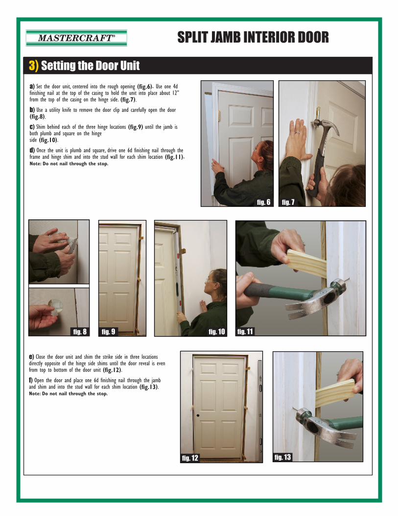
3) Setting the Door Unit
fig. 8 fig. 11
fig. 7
fig. 10
fig. 13
fig. 6
fig. 9
fig. 12
a) Set the door unit, centered into the rough opening (fig.6). Use one 4d finishing nail at the top of the casing to hold the unit into place about 12” from the top of the casing on the hinge side. (fig.7).
b) Use a utility knife to remove the door clip and carefully open the door (fig.8).
c) Shim behind each of the three hinge locations (fig.9) until the jamb is both plumb and square on the hinge side (fig.10).
d) Once the unit is plumb and square, drive one 6d finishing nail through the frame and hinge shim and into the stud wall for each shim location (fig.11). Note: Do not nail through the stop.
e) Close the door unit and shim the strike side in three locations directly opposite of the hinge side shims until the door reveal is even from top to bottom of the door unit (fig.12).
f) Open the door and place one 6d finishing nail through the jamb and shim and into the stud wall for each shim location (fig.13). Note: Do not nail through the stop.

SPLIT JAMB INTERIOR DOOR4) Installing the Frame
fig. 16
fig. 19
fig. 15
fig. 18fig. 17 fig. 20
a) Once the shim locations are nailed in place, cut each shim location flush with the first half of the frame (fig.14). b) Using the second half of the frame, (set aside in Step 2), carefully slide the two halves of the frame together. Push the frame into place until the casing is tight against the wall around the entire perimeter of the frame (fig.15). c) Using 6d finishing nails, nail both halves of the frame together by nailing directly through the center of the stop. Place one nail in each shim location (fig.16).
d) Open the door unit and remove two of the top hinge screws. Replace these with (2) #8 x 2 ½” construction screws. This will help prevent the door from sagging over time (fig.17).
e) Finish by nailing the casing to the wall on both sides using 4d finishing nails (fig.18). Note: For a more finished look, use a nail set and a hammer to countersink the nail heads. Use a matching filler to fill all nail holes (fig.19 & 20).
fig. 14
Apply a minimum of two coats of paint, varnish, or sealer to all exposed wood surfaces as directed by the manufacturer of the finish materials. Avoid applying sealers to any vinyl or non-wood parts.
For proper handling and disposal of construction waste materials please consult your local building codes. Additional disposal and recycling recommendations can be found on the EPA website at www.epa.com
For more information, including troubleshooting help, please visit
www.midwestmanufacturing.com
6) Finishing the Door Unit
7) Disposal of Waste Materials
8) Troubleshooting Help
a) All Mastercraft doors are set up with a 2-1/8" bore hole set at either a 2-3/8" or a 2-3/4" backset (depending on door type). All cross-bores are set for a 1" drivepoint latch. This is done to allowinstallers to utilize drive point latch systems, radius plate sytems, or square plate systems (fig.21).b) To install the backset as a drivepoint system, simply follow the lock manu-facturers instruction for converting to a drivepoint. Hammer the drivepoint into place making sure the angled portion of the backset faces the jamb (fig.22).c) Using the manufacturers instructions, install the lockset (fig.23).
5) Installing the Lockset
fig. 23fig. 22 fig. 24 fig. 25
fig. 21
d) Install the strike plate on the jamb. Our jambs are mortised for a ¼" radius strike plate. If the lock manufacturer has supplied a square plate, mark the outside edge (fig.24) and use a chisel to remove the excess wood material from around the corners of the plate (fig.25).