Embed Size (px)
Citation preview

INTERLIFT
ILF
INSTALLATION MANUAL
& CHECK-OFF SHEET
Rev. 1.2, Date 08-04-2011
INTERLIFT, INC. a member of MBB
15939 Piuma Ave., Cerritos, CA 90703 Tel (888)-774-5844 Fax (562) 924-8318
Visit our website at www.interlift.net for up to date information and
notifications If you received this product with damaged or missing parts, contact Interlift at (888)-774-5844
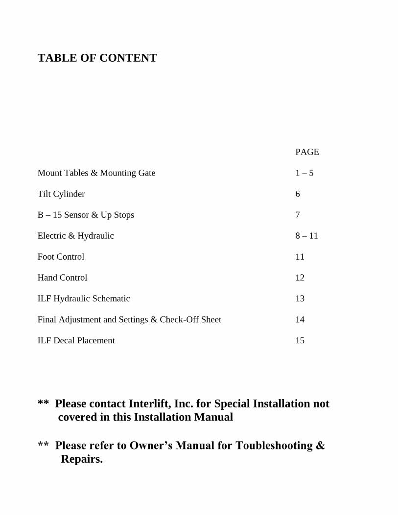
TABLE OF CONTENT
PAGE
Mount Tables & Mounting Gate 1 – 5
Tilt Cylinder 6
B – 15 Sensor & Up Stops 7
Electric & Hydraulic 8 – 11
Foot Control 11
Hand Control 12
ILF Hydraulic Schematic 13
Final Adjustment and Settings & Check-Off Sheet 14
ILF Decal Placement 15
** Please contact Interlift, Inc. for Special Installation not
covered in this Installation Manual
** Please refer to Owner’s Manual for Toubleshooting &
Repairs.

Mounting Table
F-
DIM
EN
SIO
N (
inch
es)
K DIMENSION ( inches)
35
34
33
32
31
30
29
28
27
26 25 26 27 28 29 30 31 32 33 34
14" to max 24"
F D
im M
in 2
6"
Max
33
"
K Dim Min 26"Max 34"
102"67"48"
F Dim minus 11"
Min of 8"over lap
**Bed Height Ranges: Max=Unloaded / Min=Loaded Truck
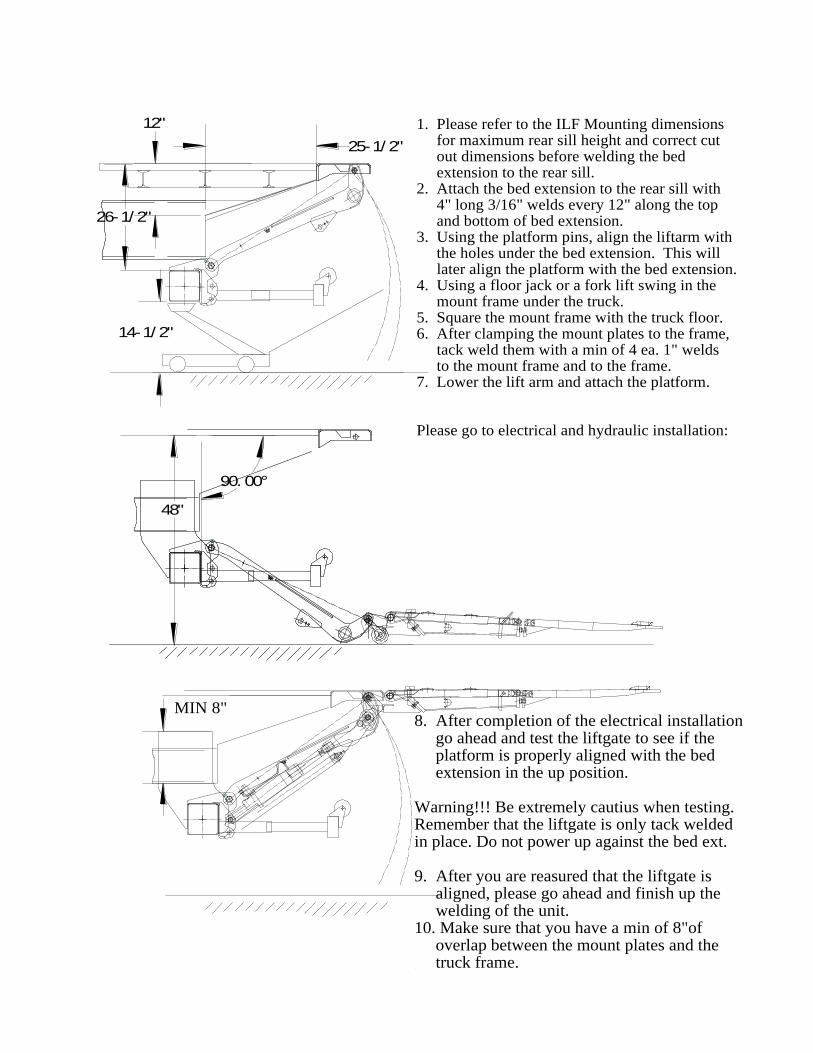
1. Please refer to the ILF Mounting dimensions for maximum rear sill height and correct cut out dimensions before welding the bed extension to the rear sill.2. Attach the bed extension to the rear sill with 4" long 3/16" welds every 12" along the top and bottom of bed extension.3. Using the platform pins, align the liftarm with the holes under the bed extension. This will later align the platform with the bed extension.4. Using a floor jack or a fork lift swing in the mount frame under the truck.5. Square the mount frame with the truck floor. 6. After clamping the mount plates to the frame, tack weld them with a min of 4 ea. 1" welds to the mount frame and to the frame.7. Lower the lift arm and attach the platform.
Please go to electrical and hydraulic installation:
8. After completion of the electrical installation go ahead and test the liftgate to see if the platform is properly aligned with the bed extension in the up position.
Warning!!! Be extremely cautius when testing.Remember that the liftgate is only tack weldedin place. Do not power up against the bed ext.
9. After you are reasured that the liftgate is aligned, please go ahead and finish up the welding of the unit.10. Make sure that you have a min of 8"of overlap between the mount plates and the truck frame.
MIN 8"
48"
26-1/ 2"
25-1/ 2"
12"
90. 00°
14-1/ 2"
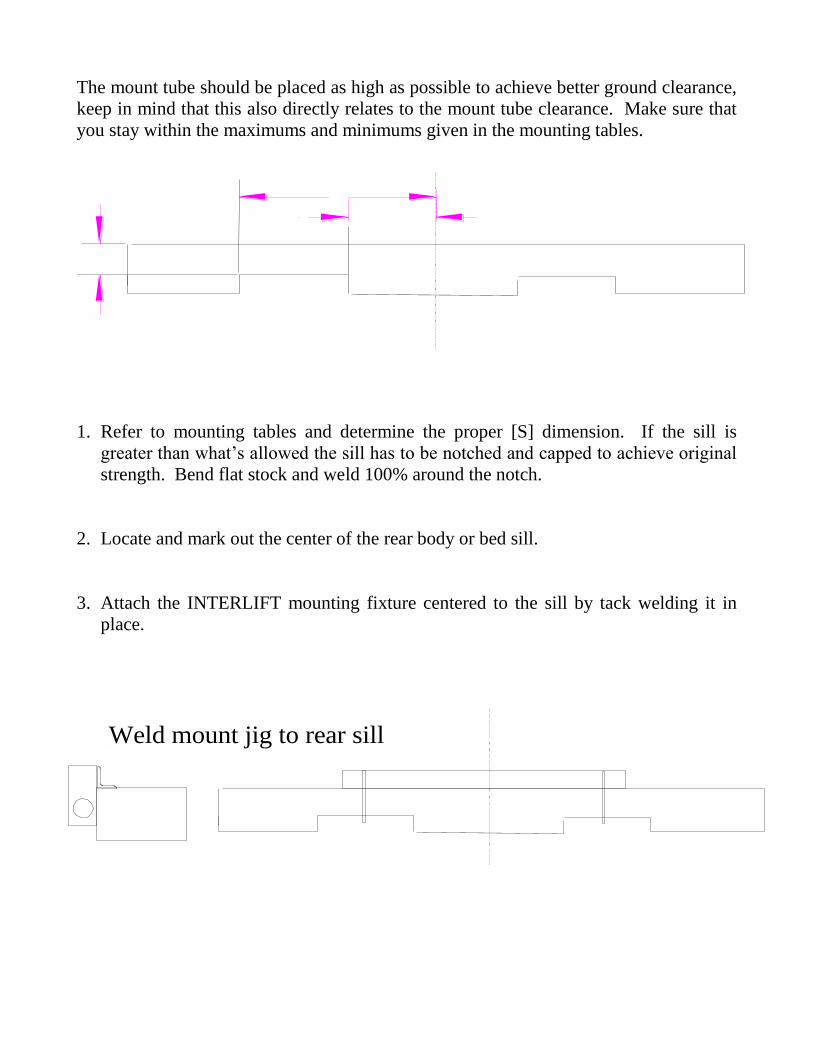
The mount tube should be placed as high as possible to achieve better ground clearance,
keep in mind that this also directly relates to the mount tube clearance. Make sure that
you stay within the maximums and minimums given in the mounting tables.
1. Refer to mounting tables and determine the proper [S] dimension. If the sill is
greater than what’s allowed the sill has to be notched and capped to achieve original
strength. Bend flat stock and weld 100% around the notch.
2. Locate and mark out the center of the rear body or bed sill.
3. Attach the INTERLIFT mounting fixture centered to the sill by tack welding it in
place.
Weld mount jig to rear sill

4. Slide mount tube in under the truck frame and attach the lift arm to the mounting
fixture or attach the two lift arm pins to the platform. At this point you should place
the mount tube in the predetermined position, keeping the given maximums and
minimums in mind. You can use a forklift, a floor jack or a similar device to
position the mount tube. Make sure that you place the tube at a 90-degree angle to
the truck bed.
5. With the mount tubes held in place, position the mount plates over tube and against
truck frame position them with angle facing forward and clamp them to truck frame.

6. Before any welding is started, please check that liftgate is balanced and not binding
in mounting fixture, you should have equal pressure on each lift-arm pin. This is
very important to make platform align with truck sill.
7. Be certain to pull out power tray before welding. The reservoir is made of plastic
and you may burn it while welding. To pull out tray, just simply remove the bolt on
the curbside and detach the ground strap and control power connector for the tray.
Pull on tray until the hoses are stretched and the tank is further out than the point of
welding.
8. Tack weld mount plates to mount tube with a minimum three one inch welds and
three one inch welds to the truck frame. Before finishing up all welding we
recommend doing the electrical installation and platform installation to make
sure that everything aligns like it should.
Use a min of 8" overlap between mount plates and truck frameWeld 100% with 1/4" weld against the frame and both sidesof the plates against the mount frame
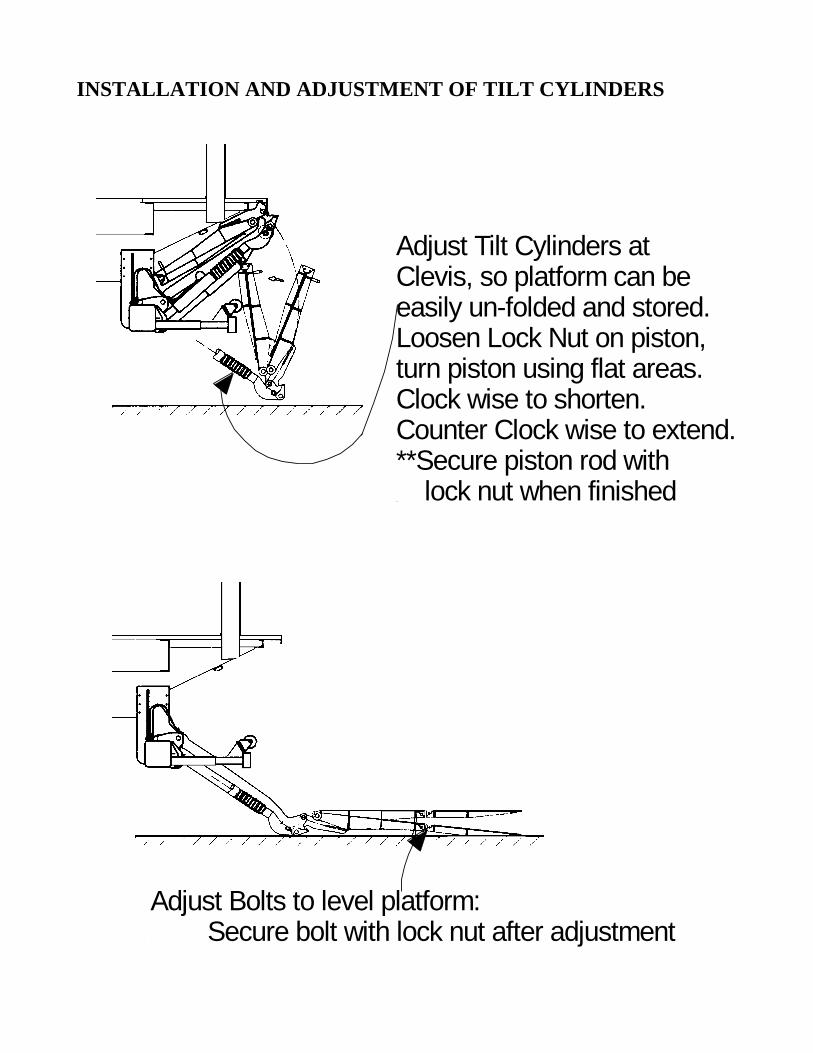
INSTALLATION AND ADJUSTMENT OF TILT CYLINDERS
Adjust Tilt Cylinders at Clevis, so platform can be easily un-folded and stored.Loosen Lock Nut on piston, turn piston using flat areas. Clock wise to shorten.Counter Clock wise to extend.**Secure piston rod with lock nut when finished
Adjust Bolts to level platform: Secure bolt with lock nut after adjustment

B – 15 SENSOR
INSTALLATION OF UP STOPS
Install up stops for the lift arm in the position where the platform is level with the floor.
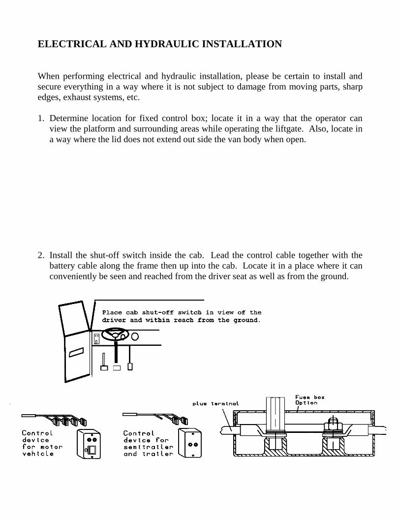
ELECTRICAL AND HYDRAULIC INSTALLATION
When performing electrical and hydraulic installation, please be certain to install and
secure everything in a way where it is not subject to damage from moving parts, sharp
edges, exhaust systems, etc.
1. Determine location for fixed control box; locate it in a way that the operator can
view the platform and surrounding areas while operating the liftgate. Also, locate in
a way where the lid does not extend out side the van body when open.
2. Install the shut-off switch inside the cab. Lead the control cable together with the
battery cable along the frame then up into the cab. Locate it in a place where it can
conveniently be seen and reached from the driver seat as well as from the ground.

BACK SIDE OF ON - OFF CAB SWITCH
DO
NO
T U
SE
4 2 (-) 1
TERMINALS ARE MARKED MBB ON GREEN BOARD OR ON WIRES
Cable wires are marked: 1, 2, 4, Green Yellow = Ground (-)
1 = Hot Lead To Red L.E.D. Lights - WHITE
(-) = Ground To L.E.D. Lights - GREEN YELLOW
2 = 12 Volt Power From Batteries - RED
4 = Control Power To Liftgate - BLUE
3. Install the battery cable between power pack and battery. Also, install the two 10
gauge wires for the control power to the batteries. Blue to positive with an in-
line fuse at the battery, brown to negative. Connect the power cable for the gate
to the positive terminal on the battery. Secure the cable ever 12 inches against the
frame with frame clips. Never secure cable in a way where it can make contact
with other wiring, brake fuel or airlines etc or get pinched against other objects.
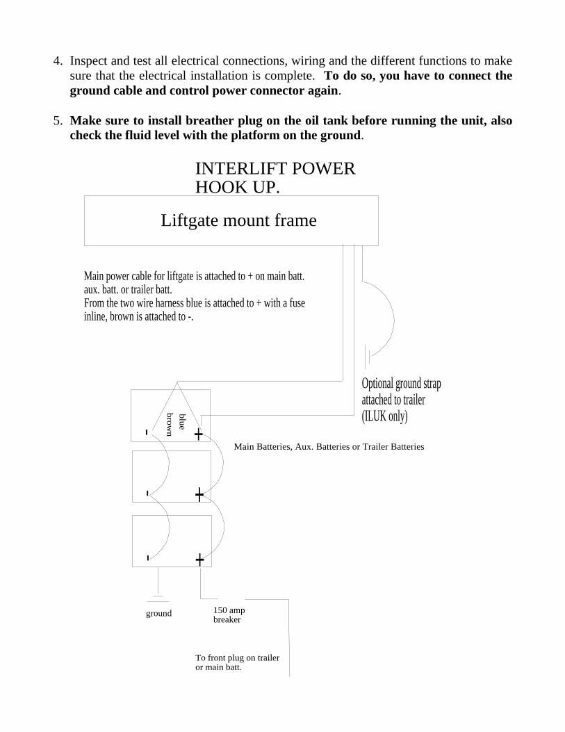
4. Inspect and test all electrical connections, wiring and the different functions to make
sure that the electrical installation is complete. To do so, you have to connect the
ground cable and control power connector again.
5. Make sure to install breather plug on the oil tank before running the unit, also
check the fluid level with the platform on the ground.
+-
+-
+-
Main power cable for liftgate is attached to + on main batt. aux. batt. or trailer batt. From the two wire harness blue is attached to + with a fuseinline, brown is attached to -.
blu
e
bro
wn
150 ampbreaker
To front plug on traileror main batt.
ground
Optional ground strap attached to trailer (ILUK only)
INTERLIFT POWER HOOK UP.
Main Batteries, Aux. Batteries or Trailer Batteries
Liftgate mount frame
6. When the platform is in the correct position in relation to truck sill, it is time to finish
welding of mount tube. Make sure to have power pack pulled out when welding
the tube.
7. Weld tube and mount plates with a 1/4” fillet weld 100% of the area around mount
tube and around frame on both sides of plates. The plates must have a minimum of
8” of overlap on the frame.
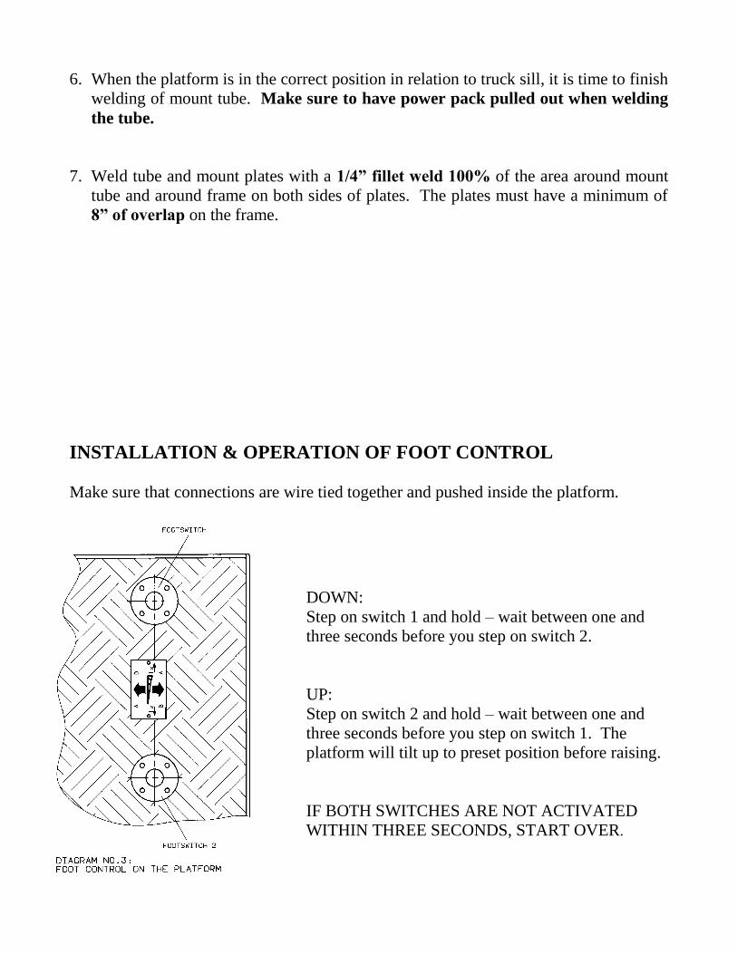
INSTALLATION & OPERATION OF FOOT CONTROL
Make sure that connections are wire tied together and pushed inside the platform.
DOWN:
Step on switch 1 and hold – wait between one and
three seconds before you step on switch 2.
UP:
Step on switch 2 and hold – wait between one and
three seconds before you step on switch 1. The
platform will tilt up to preset position before raising.
IF BOTH SWITCHES ARE NOT ACTIVATED
WITHIN THREE SECONDS, START OVER.
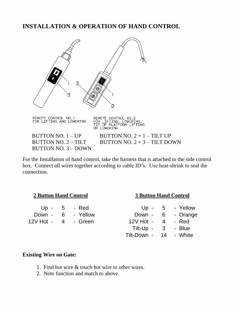
INSTALLATION & OPERATION OF HAND CONTROL
BUTTON NO. 1 – UP BUTTON NO. 2 + 1 – TILT UP
BUTTON NO. 2 – TILT BUTTON NO. 2 + 3 – TILT DOWN
BUTTON NO. 3 – DOWN
For the Installation of hand control, take the harness that is attached to the side control
box. Connect all wires together according to cable ID’s. Use heat-shrink to seal the
connection.
2 Button Hand Control 3 Button Hand Control
Up - 5 - Red Up - 5 - Yellow
Down - 6 - Yellow Down - 6 - Orange
12V Hot - 4 - Green 12V Hot - 4 - Red
Tilt-Up - 3 - Blue
Tilt-Down - 14 - White
Existing Wire on Gate:
1. Find hot wire & touch hot wire to other wires.
2. Note function and match to above.

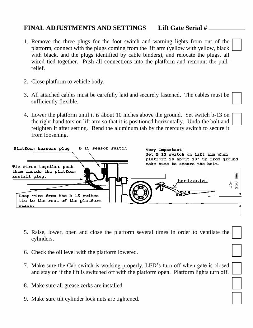
FINAL ADJUSTMENTS AND SETTINGS Lift Gate Serial #
1. Remove the three plugs for the foot switch and warning lights from out of the
platform, connect with the plugs coming from the lift arm (yellow with yellow, black
with black, and the plugs identified by cable binders), and relocate the plugs, all
wired tied together. Push all connections into the platform and remount the pull-
relief.
2. Close platform to vehicle body.
3. All attached cables must be carefully laid and securely fastened. The cables must be
sufficiently flexible.
4. Lower the platform until it is about 10 inches above the ground. Set switch b-13 on
the right-hand torsion lift arm so that it is positioned horizontally. Undo the bolt and
retighten it after setting. Bend the aluminum tab by the mercury switch to secure it
from loosening.
5. Raise, lower, open and close the platform several times in order to ventilate the
cylinders.
6. Check the oil level with the platform lowered.
7. Make sure the Cab switch is working properly, LED’s turn off when gate is closed
and stay on if the lift is switched off with the platform open. Platform lights turn off.
8. Make sure all grease zerks are installed
9. Make sure tilt cylinder lock nuts are tightened.

ILF DECAL PLACEMENT For operator safety, all decals appearing in “Decal Kit” must be in a conspicuous place on control side
of liftgate. This is typically a combination of decals on the liftgate and truck or trailer body. Please
make sure to place the maximum capacity decal (C) on driver and curb side.
(A) 1 ATG-URGWA - Urgent warning: Elevating gate instructions
(C) 1 ATG-BKR - Circuit Breaker Reset (must be located at the circuit breaker)
(D) 2 ATG-XXXX - Max. Capacity (please check the serial number plate to find out your specific
capacity)
(E) 1 ATG-RESET - Circuit Breaker Protection
(F) 2 ATG-WLH - Warning: liftgate can crush
(G) 2 ATG-CTN - Caution: Always stand clear of platform area
(H) 1 ATG-CAB - Liftgate Shut-Off (Place Decal next to the On-Off Switch in the Cab)
(K) 1 ATG-WNG - Warning: Use handle to open (must be located underneath handle (main section))
(L) 1 ATG-FT- Notice for Foot Control (if applicable)
Decal - A
Decal - C
Decal - D
Decal - H
Decal - E
Decal - F
Decal - G Decal - K Decal - L

(A) 1 ATG-URGWA - Urgent warning: Elevating gate instructions
(B) 1 ATG-ILR-ILFS - Operational Instructions
(C) 1 ATG-BKR - Circuit Breaker Reset (must be located at the circuit breaker)
(D) 2 ATG-XXXX - Max. Capacity (please check the serial number plate to fi
(E) 1 ATG-RESET - Circuit Breaker Protection
Decal G
Decal A
Decal E
Decal D
Decal F
Decal K
Decal L