Embed Size (px)
Citation preview
EN
Operating Instructions
Interlocking/Locking Modules
MGB2-I..-MLI-... / MGB2-L..-MLI-... (Modular)
from V1.00.0

Operating Instructions Interlocking/Locking ModulesMGB2-I..-MLI-... / MGB2-L..-MLI-... (Modular)
2 (Translation of the original operating instructions) 2500234-04-09/20
Contents
1. About this document ............................................................................................. 41.1. Scope ............................................................................................................................................4
1.1.1. Notes on older product versions ......................................................................................41.2. Target group ..................................................................................................................................4
1.3. Key to symbols ...............................................................................................................................4
1.4. Supplementary documents ..............................................................................................................4
2. Correct use .......................................................................................................... 5
3. Description of the safety function .......................................................................... 7
4. Exclusion of liability and warranty ......................................................................... 9
5. General safety precautions ................................................................................... 9
6. Function ............................................................................................................. 106.1. Interlocking module MGB2-I... (or a correspondingly configured MGB2-L2) .........................................10
6.2. Locking module MGB2-L... .............................................................................................................106.2.1. Guard locking for version MGB2-L1 ................................................................................106.2.2. Guard locking for version MGB2-L2 ................................................................................11
6.3. Control of guard locking MGB2-L1 and MGB2-L2 .............................................................................11
7. System overview................................................................................................. 127.1. Interlocking/locking module MGB2-I../MGB2-L.. ...............................................................................12
7.2. Handle module MGB2-H-….............................................................................................................13
7.3. Escape release MGB-E-... (optional) ................................................................................................13
7.4. Dimension drawings ......................................................................................................................147.4.1. Interlocking/locking module MGB2-I.../MGB2-L... .............................................................147.4.2. Handle module MGB2-H... ..............................................................................................147.4.3. Escape release MGB-E-... ..............................................................................................157.4.4. Assembly of MGB2-L, MGB2-H and MGB-E (example on profile 40x40) ...............................167.4.5. Drilling pattern, complete system with bus module MBM and optional extension module MCM .
177.4.6. Drilling pattern, escape release MGB-E ...........................................................................18
8. Manual release ................................................................................................... 198.1. Auxiliary release............................................................................................................................19
8.2. Lockout mechanism ......................................................................................................................20
8.3. Escape release (optional) ..............................................................................................................208.3.1. Preparing escape release ..............................................................................................21
9. Mounting ............................................................................................................ 229.1. Replacing modules........................................................................................................................23
9.2. Mounting submodules ...................................................................................................................23
9.3. Replacing submodules ..................................................................................................................249.3.1. Replacing faulty submodule ...........................................................................................249.3.2. Replacing submodule with a submodule with a different function (changing configuration) ...249.3.3. Fitting and removing lenses and labels for controls and indicators ....................................25

32500234-04-09/20 (Translation of the original operating instructions)
Operating Instructions Interlocking/Locking ModulesMGB2-I..-MLI-... / MGB2-L..-MLI-... (Modular)
EN
10. Changing the door hinge position ........................................................................ 2610.1. Changing the interlocking/locking module to a different door hinge position ......................................26
10.2. Changing actuating direction of the handle module ..........................................................................26
11. Protection against environmental effects ............................................................. 28
12. Controls and indicators ....................................................................................... 28
13. Electrical connection .......................................................................................... 2913.1. Connecting modules .....................................................................................................................29
13.2. Using submodules ........................................................................................................................30
14. Data blocks for interlocking/locking module MGB2-I or MGB2-L .......................... 31
15. Setup ................................................................................................................. 3115.1. Teach-in operation (only for MGB2 unicode) .....................................................................................31
15.2. Mechanical function test ................................................................................................................32
15.3. Electrical function test ...................................................................................................................32
15.4. Replacing a module .....................................................................................................................32
16. System status table, module LEDs ....................................................................... 3316.1. System indications if there are faults (module LEDs) ........................................................................33
16.2. System indications during setup, teach-in and normal operation .......................................................34
17. System status table (slot LEDs) ........................................................................... 35
18. Technical data .................................................................................................... 3618.1. Radio frequency approvals.............................................................................................................37
19. Troubleshooting and assistance ........................................................................... 3819.1. Resetting general faults .................................................................................................................38
19.2. Fault on actuating the escape release ............................................................................................38
19.3. Resetting system to factory settings ..............................................................................................38
20. Service .............................................................................................................. 39
21. Inspection and service ........................................................................................ 39
22. Declaration of conformity ................................................................................... 40

Operating Instructions Interlocking/Locking ModulesMGB2-I..-MLI-... / MGB2-L..-MLI-... (Modular)
4 (Translation of the original operating instructions) 2500234-04-09/20
1. About this document1.1. ScopeThese operating instructions are valid for all Interlocking/Locking Modules MGB2-I..-MLI-... / MGB2-L..-MLI-... (Modular). These operating instructions, the document Safety information, the operating instructions for the bus module MBM and any enclosed data sheet form the complete user information for your device.
Series Guard locking types System families Product versions
MGB2
I (without guard locking)…-MLI-… (operation on a bus module MBM)
from V1.00.0
L1 (guard locking by spring force) from V1.00.0
L2 (guard locking by solenoid force) from V1.00.0
1.1.1. Notes on older product versions
Products with lower product versions or without a version number are not described by these operating instructions. Please contact our support team in this case.
1.2. Target groupDesign engineers and installation planners for safety systems on machines, as well as setup and servicing staff possessing special expertise in handling safety components as well as expertise in the installation, setup, programming and diagnostics of programmable logic controllers (PLCs) and bus systems.
1.3. Key to symbolsSymbol/depiction Meaning
Printed document
Internet
www Document is available for download at www.EUCHNER.com
DANGER WARNING CAUTION
Safety precautionsDanger of death or severe injuriesWarning about possible injuriesCaution Slight injuries possible
NOTICE Important!
Notice about possible device damageImportant information
Tip Useful information
1.4. Supplementary documentsThe overall documentation for this device consists of the following documents:
Document title(document number) Contents
Safety information(2525460) Basic safety information
Operating Instructions Interlocking/Locking Modules MGB2-L..-MLI(2500234)
(this document) Internet
www
Operating Instructions Bus Modules MBM-..-MLI (2500235)
Configuration manual for the connection to the bus and data evaluation in MLI systems Internet
www
Possibly enclosed data sheets Article-specific information with deviations or additions to the operating instructions as well as data sheets for submodules
Important!
Always read all documents to gain a complete overview of safe installation, setup and use of the device. The documents can be downloaded from www.euchner.com. For this purpose enter the doc. no. in the search box.

52500234-04-09/20 (Translation of the original operating instructions)
Operating Instructions Interlocking/Locking ModulesMGB2-I..-MLI-... / MGB2-L..-MLI-... (Modular)
EN
2. Correct useThe Modular devices described here can be operated only with a suitable bus module MBM-...-MLI-....
For the MGB2-I... the following applies:
Along with the bus module MBM, the system consists of at least one interlocking module MGB2-I... and one handle module MGB2-H…
The safety system MGB2-I... is an interlocking device without guard locking (type 4). Devices with unicode evaluation possess a high coding level, devices with multicode evaluation possess a low coding level.
In combination with a movable guard and the machine control, this safety component prevents dangerous machine functions from occurring while the guard is open. A stop command is triggered if the guard is opened during the dangerous machine function.
This means: Ì Starting commands that cause a dangerous machine function must become active only when the guard is closed. Ì Opening the guard triggers a stop command. Ì Closing a guard must not cause automatic starting of a dangerous machine function. A separate start command must be issued. For exceptions, refer to EN ISO 12100 or relevant C-standards.
For the MGB2-L... the following applies:
Along with the bus module MBM, the system consists of at least one locking module MGB2-L... and one handle module MGB2-H…
The safety system MGB2-L... is an interlocking device with guard locking (type 4). Devices with unicode evaluation possess a high coding level, devices with multicode evaluation possess a low coding level.
In combination with a movable guard and the machine control, this safety component prevents the guard from being opened while a dangerous machine function is being performed.
This means: Ì The unlocking of the guard locking by the control system triggers a stop command. Ì Starting commands that cause a dangerous machine function must become active only when the guard is closed and locked. Ì The guard locking must not be released until the dangerous machine function has ended. Ì Closing and locking a guard must not cause automatic starting of a dangerous machine function. A separate start com-mand must be issued. For exceptions, refer to EN ISO 12100 or relevant C-standards.
For MGB2-I.. /MGB2-L..
Before the device is used, a risk assessment must be performed on the machine, e.g. in accordance with the following standards: Ì EN ISO 13849-1 Ì EN ISO 12100 Ì EN IEC 62061

Operating Instructions Interlocking/Locking ModulesMGB2-I..-MLI-... / MGB2-L..-MLI-... (Modular)
6 (Translation of the original operating instructions) 2500234-04-09/20
Correct use includes observing the relevant requirements for installation and operation, particularly based on the following standards: Ì EN ISO 13849-1 Ì EN ISO 14119 Ì EN IEC 60204-1 Ì EN IEC 62061
The safety system MGB2-.-MLI... is only allowed to be combined with suitable MLI modules (see Table 1: Combination options for modules with MLI technology).
On the modification of system components, EUCHNER provides no warranty for function.
The customer is responsible for the safe overall function, especially for the safe integration into an overall system.
Important!
Ì The user is responsible for the proper integration of the device into a safe overall system. For this purpose, the overall system must be validated, e.g. in accordance with EN ISO 13849-2. Ì Correct use requires observing the permissible operating parameters (see chapter 18. Technical data on page 36). Ì If a data sheet is included with the product, the information on the data sheet applies.
Table 1: Combination options for modules with MLI technology
Bus module Base units
Handle module Submodules Submodules Submodules
MGB2-H-...from V1.00.0
MSM-.-P-...MSM-.-R-...MSM-.-N-...
MSM-.-E-... MSM-.-K-...
MBM-...-MLIfrom V1.00.0
Interlocking/locking moduleMGB2-I..-MLI/MGB2-L..-MLI
from V1.00.0- -
Extension moduleMCM-...-MLI - -
Key to symbolsCombination possible
- Combination not possible

72500234-04-09/20 (Translation of the original operating instructions)
Operating Instructions Interlocking/Locking ModulesMGB2-I..-MLI-... / MGB2-L..-MLI-... (Modular)
EN
3. Description of the safety functionImportant!
You will find detailed instructions on the determination of reliability values in the operating instructions for your bus module.
Devices from this series feature the following safety functions:
For the MGB2-L... the following applies:
Monitoring of guard locking and the position of the guard (interlocking device with guard locking according to EN ISO 14119)
Ì Safety function (see chapter 6. Function on page 10): - If guard locking is released, safety bit LM.I_UK (ÜK) = 0 (monitoring of the locking element). - If the guard is open, safety bit LM.I_SK (SK) = 0 (monitoring of the position of the guard). - Guard locking can be activated only when the bolt tongue is located in the locking module (prevention of inadvertent locking position (faulty closure protection)).
PLC
PFHD, Sys
PFHD, MBMPFHD, MGB2-L
Guardlocking Device
MGB2-L...
Busmodule MBM
EUCHNER ModuleLink-System (MLI)
Safetybit LM.FI_UK_(Guardlock monitoring)
Ì Safety characteristics: category, Performance Level, PFHD (reliability values according to EN 13849-1 see 18. Technical data).
Control of guard locking (safety bit FO_CL) Ì Safety function: If the device is used as guard locking for personnel protection, control of guard locking must be regarded as a safety function. The safety level of guard locking control is determined by the system PFHD sys. and by the external control (e.g. safe PLC).
PFHD, ext.
PFHD, Sys
Guardlocking Device
MGB2-L...
Busmodule MBM
EUCHNER ModuleLink-System (MLI)
(e.g. standstill monitor)
Safetybit FO_CL(Guardlocking)
PFHD, MBM PFHD, MGB2-L
Ì Safety characteristics of bus module MBM and locking module MGB2-L: category, Performance Level, PFHD (reliability values according to EN 13849-1, see 18. Technical data).

Operating Instructions Interlocking/Locking ModulesMGB2-I..-MLI-... / MGB2-L..-MLI-... (Modular)
8 (Translation of the original operating instructions) 2500234-04-09/20
For MGB2-I... (or a correspondingly configured MGB2-L...) the following applies:
Monitoring of the guard position (interlocking device according to EN ISO 14119)
Ì Safety function: When the guard is open, safety bit LM.I_SK (SK) = 0. (See chapter 6. Function on page 10.)
PLC
PFHD, Sys
PFHD, MBMPFHD, MGB2-I
Interlocking Device
MGB2-L...
Busmodule MBM
EUCHNER ModuleLink-System (MLI)
Safetybit LM.FI_SK_(Interlock monitoring)
Ì Safety characteristics: category, Performance Level, PFHD (reliability values according to EN 13849-1, see 18. Technical data).
Evaluation of submodules with safety function
If you use submodules MSM with safety function in the interlocking/locking module, please observe the description of the safety functions in the operating instructions for your bus module MBM and in any data sheet for your submodule MSM.

92500234-04-09/20 (Translation of the original operating instructions)
Operating Instructions Interlocking/Locking ModulesMGB2-I..-MLI-... / MGB2-L..-MLI-... (Modular)
EN
4. Exclusion of liability and warrantyIn case of failure to comply with the conditions for correct use stated above, or if the safety regulations are not followed, or if any servicing is not performed as required, liability will be excluded and the warranty void.
5. General safety precautionsSafety switches fulfill personnel protection functions. Incorrect installation or tampering can lead to fatal injuries to personnel.
Check the safe function of the safeguard and, if necessary, other safety functions particularly Ì after any setup work Ì each time after replacement of a component relevant to safety Ì after an extended period without use Ì after every fault Ì after any change to the DIP switch settings
Independent of these checks, the safe function of the safeguard should be checked at suitable intervals as part of the maintenance schedule.
WARNING
Danger to life due to improper installation or due to bypassing (tampering). Safety components perform a personnel protection function. Ì Safety components must not be bypassed, turned away, removed or otherwise rendered ineffec-tive. On this topic pay attention in particular to the measures for reducing the possibility of bypass-ing according to EN ISO 14119:2013, section 7. Ì The switching operation is allowed to be triggered only by the intended handle module MGB2-H… that is positively fastened to the guard. Ì Prevent bypassing by means of replacement actuators (only for multicode evaluation). For this purpose, restrict access to actuators and to keys for releases, for example. Ì Mounting, electrical connection and setup only by authorized personnel possessing the following knowledge: - specialist knowledge in handling safety components - knowledge about the applicable EMC regulations - knowledge about the applicable regulations on operational safety and accident prevention.
Important!
Prior to use, read the operating instructions and keep these in a safe place. Ensure the operating instructions are always available during mounting, setup and servicing. For this reason you should archive a printed copy of the operating instructions. You can download the operating instructions from www.euchner.com.

Operating Instructions Interlocking/Locking ModulesMGB2-I..-MLI-... / MGB2-L..-MLI-... (Modular)
10 (Translation of the original operating instructions) 2500234-04-09/20
6. Function6.1. Interlocking module MGB2-I... (or a correspondingly configured MGB2-L2)Together with a handle module, the interlocking module makes it possible to interlock movable guards. The combination also serves as a mechanical door stop at the same time.
The following switch-on conditions apply to safety bit LM.FI_SK (SK): Ì Guard closed Ì Bolt tongue inserted into the interlocking module
See also chapter 16.2. System indications during setup, teach-in and normal operation on page 34 and the operating instructions for bus module MBM.
The interlocking module detects the position of the guard and the position of the bolt tongue. The bolt tongue in the handle module is moved into and out of the interlocking module by actuating the door handle.
6.2. Locking module MGB2-L...Together with a handle module, the locking module makes it possible to lock movable guards. The combination also serves as a mechanical door stop at the same time. There are various configurations for the control of the guard locking (see section 6.3. Control of guard locking MGB2-L1 and MGB2-L2). The following descriptions in 6.2.1 and 6.2.2 describe the function of the guard locking with the factory setting.
Important!
To operate the device as guard locking for personnel protection according to EN ISO 14119, the safety bit LM.FI_UK (ÜK) must be evaluated.
The following switch-on conditions apply to the safety bit LM.FI_UK (ÜK): Ì Guard closed Ì Bolt tongue inserted into the locking module Ì Guard locking in locking position (guard lock monitoring)
See also chapter 16.2. System indications during setup, teach-in and normal operation on page 34 and the operating instructions for bus module MBM.
The locking module detects the position of the guard and the position of the bolt tongue. The position of the guard locking is also monitored. The bolt tongue in the handle module is moved into and out of the locking module by actuating the door handle.
If the bolt tongue is fully inserted into the locking module, the guard locking can lock the bolt tongue in this position. De-pending on version, this locking is by spring force or solenoid force.
6.2.1. Guard locking for version MGB2-L1
(guard locking actuated by spring force and released by power-ON)
Guard locking: Close guard; no voltage at the solenoid (with factory setting: safety bit LM.FO_CL = 0.)
Releasing guard locking: Apply voltage to the solenoid (with factory setting: safety bit LM.FO_CL = 1).
The spring-operated guard locking functions in accordance with the closed-circuit current principle. If the voltage is interrupted at the solenoid, the guard locking remains active and the guard cannot be opened directly.
Important!
If the guard is open when the power supply is interrupted and is then closed, guard locking is activated. This can lead to persons being locked in unintentionally.
As long as the guard locking is closed, the bolt tongue cannot be pulled out of the locking module and the guard is locked.
If voltage is applied to the guard locking solenoid, the guard locking is opened and bolt tongue is released. The guard can be opened.
In addition to the safety bit LM.FO_CL, the non-safe bit LM.O_CL can be used to control guard locking. Refer to the table in chapter 6.3. Control of guard locking MGB2-L1 and MGB2-L2 for the exact configuration.

112500234-04-09/20 (Translation of the original operating instructions)
Operating Instructions Interlocking/Locking ModulesMGB2-I..-MLI-... / MGB2-L..-MLI-... (Modular)
EN
6.2.2. Guard locking for version MGB2-L2
(guard locking actuated by power-ON and released by spring force)
Important!
Ì Use as guard locking for personnel protection is possible only in special cases, after strict assess-ment of the accident risk (see EN ISO 14119:2013, section 5.7.1)! Ì Guard locking will be released during power-up or if communication is lost.
Guard locking: Apply voltage to the solenoid (with factory setting: safety bit LM.FO_CL = 0).
Releasing guard locking: Disconnect voltage from the solenoid (with factory setting: safety bit LM.FO_CL = 1).
The magnetically actuated guard locking operates in accordance with the open-circuit current principle. If the voltage is interrupted at the solenoid, the guard locking is released and the guard can be opened directly!
The guard can be opened as long as no voltage is applied to the guard locking solenoid.
If voltage is present at the guard locking solenoid, the guard locking is held in the locked position and the guard is locked.
In addition to the safety bit LM.FO_CL, the non-safe bit LM.O_CL can be used to control guard locking. Refer to the table in chapter 6.3. Control of guard locking MGB2-L1 and MGB2-L2 for the exact configuration.
6.3. Control of guard locking MGB2-L1 and MGB2-L2By changing the parameters in the configuration tool for your control system, you can set which bit combinations are to be used to control the guard locking. You will find an overview of the parameters in the operating instructions for the bus module MBM.
On the use of the guard locking for personnel protection, as standard the guard locking must be controlled from the safe control area.
On use as guard locking for process protection, the guard locking can also be controlled exclusively using a non-safe bit.
The following table shows the possible configurations.
Type of lock-ing module
Use of the control bits for guard lockingApplicationConfiguration 1
(factory setting) Configuration 2 Configuration 3 Configuration 4
MGB2-L1 LM.FO_CL LM.FO_CL + LM.O_CL - - Guard locking for personnel pro-tection.
MGB2-L2 LM.FO_CL LM.FO_CL + LM.O_CL - - Guard locking for personnel pro-tection. Important: pay attention to
section 6.2.2.
- - LM.O_CL - Interlocking with guard locking for process protection.
- - - Control is not configured in the parameters
Interlocking. Only position mon-itoring of the guard. No locking
function.

Operating Instructions Interlocking/Locking ModulesMGB2-I..-MLI-... / MGB2-L..-MLI-... (Modular)
12 (Translation of the original operating instructions) 2500234-04-09/20
7. System overviewEscape release (optional)(MGB-E-...)
Handle module(MGB2-H...)
Interlocking/locking module(MGB2-I.../MGB2-L...)
Profinet bus module(MBM-...)
Figure 1: Components at a glance
7.1. Interlocking/locking module MGB2-I../MGB2-L..
1
2
3 4
5
6
5
SLOT 1SLOT 2
Key:1 Module function LED indicators2 Auxiliary marking for correct alignment in relation to the handle module3 Auxiliary release (optional, only on version with guard locking)4 LED indicator for submodule in SLOT 1 and SLOT 25 Top and bottom connection for the connection between modules6 Submodules in SLOT 1 and SLOT 2 (configuration example)
Notice: Depending on version, no submodules or different submodules may be inserted. See enclosed data sheet.
Figure 2: Interlocking/locking module MGB2-I.. /MGB2-L..

132500234-04-09/20 (Translation of the original operating instructions)
Operating Instructions Interlocking/Locking ModulesMGB2-I..-MLI-... / MGB2-L..-MLI-... (Modular)
EN
7.2. Handle module MGB2-H-…
1
2
3
45
6
Key:1 Door handle2 Hinged lockout mechanism3 Automatically extending lockout mechanism (optional)4 Auxiliary markings for max. permissible mounting distance5 Bolt tongue6 Locking bolt for handle adjustment
Figure 3: Handle module MGB2-H-…
7.3. Escape release MGB-E-... (optional)
1 2 3 4
Key:1 Door handle2 Housing3 Actuation axis 8 x 8 mm
(different lengths available)4 Protective sleeve
Notice: Depending on version, a mounting plate can be included. See enclosed data sheet.
Figure 4: Escape release MGB-E-...

Operating Instructions Interlocking/Locking ModulesMGB2-I..-MLI-... / MGB2-L..-MLI-... (Modular)
14 (Translation of the original operating instructions) 2500234-04-09/20
7.4. Dimension drawings7.4.1. Interlocking/locking module MGB2-I.../MGB2-L...
155
114
M12x1
10,
3
52,
5
92,
5
15 25
6,3
A
A
25,
6
12 max.
A-A
7.4.2. Handle module MGB2-H...
130 146
114
159
53
63
16,5
89,
4
15
6,3
A
A
12 max.
8 m
ax.
25,
6
A
37
30
21
min. 610
A
max.
A-A

152500234-04-09/20 (Translation of the original operating instructions)
Operating Instructions Interlocking/Locking ModulesMGB2-I..-MLI-... / MGB2-L..-MLI-... (Modular)
EN
7.4.3. Escape release MGB-E-...
89,
5 1
04,5
24 7,5
6,5
114 110 2
2 8
4
6

Operating Instructions Interlocking/Locking ModulesMGB2-I..-MLI-... / MGB2-L..-MLI-... (Modular)
16 (Translation of the original operating instructions) 2500234-04-09/20
7.4.4. Assembly of MGB2-L, MGB2-H and MGB-E (example on profile 40x40)
40 15
40
155
4
130
114
9
3
40
8
55,
5 1
07
2,4
11,
5
109
,4
114,2 110,6 6
2,3
22,
2
40
130
63
52,
5
155 4
42
115
,5
289

172500234-04-09/20 (Translation of the original operating instructions)
Operating Instructions Interlocking/Locking ModulesMGB2-I..-MLI-... / MGB2-L..-MLI-... (Modular)
EN
7.4.5. Drilling pattern, complete system with bus module MBM and optional extension module MCM
+
114
89,
4 16
73,5
6,3
(12,
3)
130
(25)
130
9
2,5
75
0 1 0
+ 0
1 0
25
16,5 15
4 ±4
15
(10,
75)
100
100 155
93
114
1
48
15
15
6,3
6,3
(9)
6,3
0 ±
4
25
25
16
MGB2-I/L MGB2-H
MCM
MBM
(9)

Operating Instructions Interlocking/Locking ModulesMGB2-I..-MLI-... / MGB2-L..-MLI-... (Modular)
18 (Translation of the original operating instructions) 2500234-04-09/20
7.4.6. Drilling pattern, escape release MGB-E
14,5
86,5 7,5
89,
4
24
6,4
MGB-E

192500234-04-09/20 (Translation of the original operating instructions)
Operating Instructions Interlocking/Locking ModulesMGB2-I..-MLI-... / MGB2-L..-MLI-... (Modular)
EN
8. Manual releaseSome situations require the guard locking to be released manually (e.g. malfunctions or an emergency). A function test should be performed after release.
More information on this topic can be found in the standard EN ISO 14119:2013, section 5.7.5.1. The device can feature the following release functions:
8.1. Auxiliary releaseIn the event of service, the guard locking can be released with the auxiliary release irrespective of the state of the solenoid (see Figure 5).
Important!
Ì Given corresponding parameter configuration, the system enters into a latching fault if the auxilia-ry release is actuated. See System status table, signal sequence incorrect status (DIA red, Lock flashes 1 time). For information on setting the related parameter, see section 19.2. Fault on actu-ating the escape release on page 38.
Important!
Ì The auxiliary release is not a safety function. Ì The machine manufacturer must select and use a suitable release (escape release, emergency release, etc.) for a specific application. A hazard assessment is required for this purpose. It may be necessary to take specifications from a product standard into account. Ì The correct function must be checked at regular intervals. Ì Loss of the release function due to mounting errors or damage during mounting. Check the re-lease function every time after mounting. Ì Please observe the notes on any enclosed data sheets.
The locking screw must be screwed in and sealed again after every use of the auxiliary release (original set of seal labels order no. 155853). Tightening torque 0.5 Nm.
1. Remove seal label or make a hole.
2. Undo locking screw.
3. Using a screwdriver, turn the auxiliary release to in the direction of the arrow.
¨ Guard locking is released.
T10
3
1
2
Figure 5: Auxiliary release

Operating Instructions Interlocking/Locking ModulesMGB2-I..-MLI-... / MGB2-L..-MLI-... (Modular)
20 (Translation of the original operating instructions) 2500234-04-09/20
8.2. Lockout mechanismIf the lockout mechanism is pivoted out, the bolt tongue cannot be extended. The lockout mechanism can be secured with padlocks (see Figure 6). This is intended to prevent people from being locked in unintentionally. The lockout mechanism does not fulfill any safety function.
¨ To pivot out, press the grooved part (possible only with bolt tongue retracted).
21
Key:1 Hinged lockout mechanism Padlock ∅ min. 2 mm, ∅ max. 10 mm
2 Automatically extending lockout mechanism (optional) Padlock ∅ min. 6 mm, ∅ max. 10 mm
Notice: You can fit up to 3 locks Ø 8 mm per lockout mechanism.
Figure 6: Lockout mechanism secured with padlock
8.3. Escape release (optional)The escape release is used to open a guard from the inside without tools.
Depending on the parameters set in your configuration environment, the system may enter into a latching fault if the escape release is actuated (see 19.2. Fault on actuating the escape release on page 38).
Important!
Ì It must be possible to actuate the escape release manually from inside the protected area without tools. Ì It must not be possible to reach the escape release from the outside. Ì The bolt tongue must not be under tensile stress during manual release. Ì The escape release meets the requirements of Category B according to EN ISO 13849-1:2015. Ì The correct function must be checked at regular intervals. Ì Please observe the notes on any enclosed data sheets.
Ì Fit escape release such that operation, inspection and maintenance are possible. Ì The actuation axis for the escape release must be inserted min. 9 mm into the handle module. Note the information on the different profile widths in the chapter 8.3.1. Preparing escape release on page 21. Ì Adjust escape release axis at right angles to the handle module. See Figure 8.
212500234-04-09/20 (Translation of the original operating instructions)
Operating Instructions Interlocking/Locking ModulesMGB2-I..-MLI-... / MGB2-L..-MLI-... (Modular)
EN
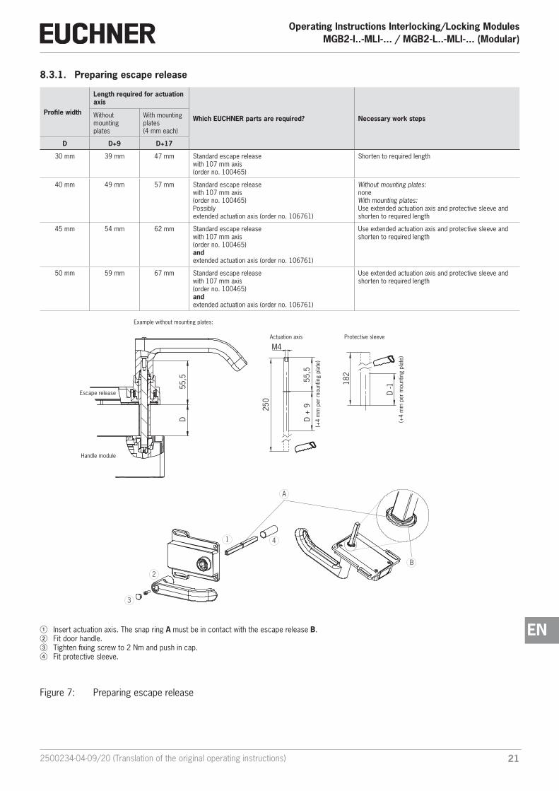
8.3.1. Preparing escape release
Profile width
Length required for actuation axis
Which EUCHNER parts are required? Necessary work stepsWithout mounting plates
With mounting plates (4 mm each)
D D+9 D+17
30 mm 39 mm 47 mm Standard escape release with 107 mm axis(order no. 100465)
Shorten to required length
40 mm 49 mm 57 mm Standard escape release with 107 mm axis(order no. 100465)Possibly extended actuation axis (order no. 106761)
Without mounting plates: noneWith mounting plates: Use extended actuation axis and protective sleeve and shorten to required length
45 mm 54 mm 62 mm Standard escape release with 107 mm axis(order no. 100465)and extended actuation axis (order no. 106761)
Use extended actuation axis and protective sleeve and shorten to required length
50 mm 59 mm 67 mm Standard escape release with 107 mm axis(order no. 100465)and extended actuation axis (order no. 106761)
Use extended actuation axis and protective sleeve and shorten to required length
55,5
M4
250
182
D +
9
D -1
D
55,
5
Example without mounting plates:
Escape release
Handle module
Actuation axis Protective sleeve
(+4
mm
per
mou
ntin
g pl
ate)
(+4
mm
per
mou
ntin
g pl
ate)
1 Insert actuation axis. The snap ring A must be in contact with the escape release B. 2 Fit door handle.3 Tighten fixing screw to 2 Nm and push in cap.4 Fit protective sleeve.
1
3
2
4
A
B
Figure 7: Preparing escape release
Operating Instructions Interlocking/Locking ModulesMGB2-I..-MLI-... / MGB2-L..-MLI-... (Modular)
22 (Translation of the original operating instructions) 2500234-04-09/20
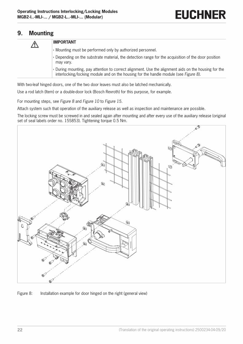
9. MountingIMPORTANT
Ì Mounting must be performed only by authorized personnel.
Ì Depending on the substrate material, the detection range for the acquisition of the door position may vary.
Ì During mounting, pay attention to correct alignment. Use the alignment aids on the housing for the interlocking/locking module and on the housing for the handle module (see Figure 8).
With two-leaf hinged doors, one of the two door leaves must also be latched mechanically.
Use a rod latch (Item) or a double-door lock (Bosch Rexroth) for this purpose, for example.
For mounting steps, see Figure 8 and Figure 10 to Figure 15.
Attach system such that operation of the auxiliary release as well as inspection and maintenance are possible.
The locking screw must be screwed in and sealed again after mounting and after every use of the auxiliary release (original set of seal labels order no. 155853). Tightening torque 0.5 Nm.
Figure 8: Installation example for door hinged on the right (general view)
232500234-04-09/20 (Translation of the original operating instructions)
Operating Instructions Interlocking/Locking ModulesMGB2-I..-MLI-... / MGB2-L..-MLI-... (Modular)
EN
9.1. Replacing modules
CAUTION
Risk of damage to equipment or malfunction as a result of uncontrolled machine stop. Ì The communication within the system is interrupted by the replacement of a module, and the safe bits are reset. If a process is running, this situation can result in an uncontrolled stop and damage to the installation or the product. Before replacement, make sure the installation is in a suitable operating status.
Modules (e.g. locking module or extension module) can be replaced only in combination with a restart of the overall system. On the disconnection of the module connection, the system enters into a fault state. The related module and all downstream modules remain inactive until the overall system is restarted (fault state).
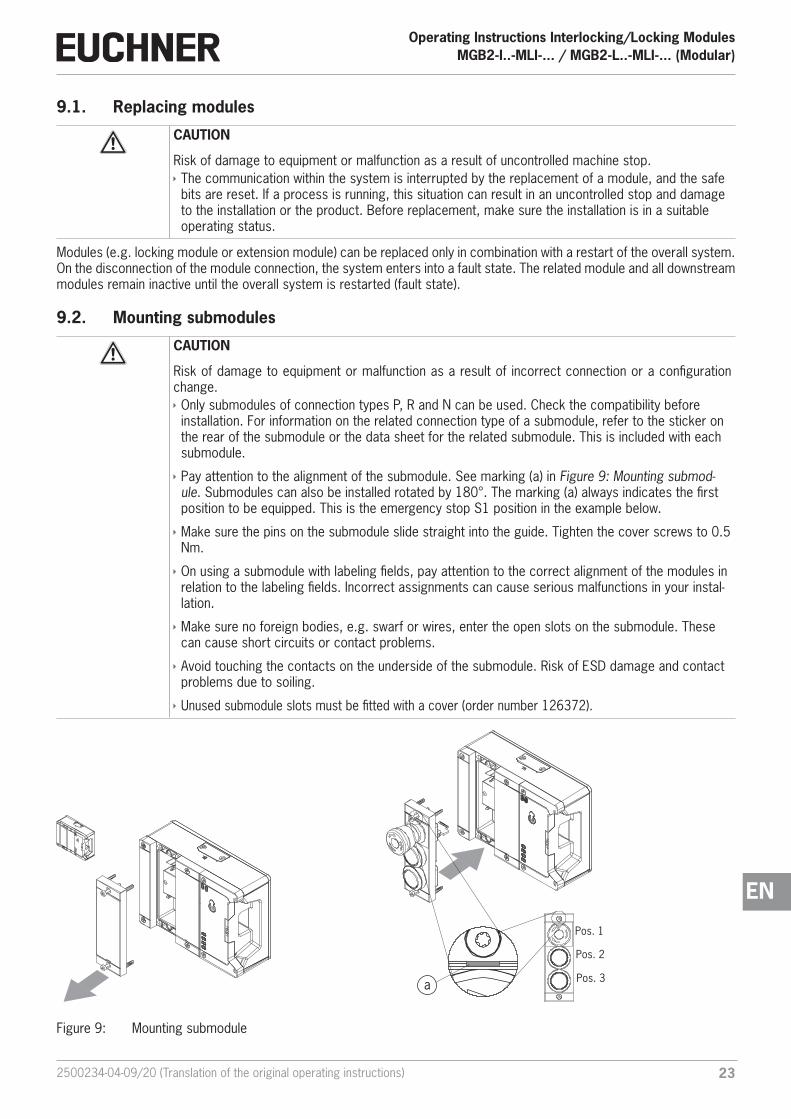
9.2. Mounting submodules
CAUTION
Risk of damage to equipment or malfunction as a result of incorrect connection or a configuration change. Ì Only submodules of connection types P, R and N can be used. Check the compatibility before installation. For information on the related connection type of a submodule, refer to the sticker on the rear of the submodule or the data sheet for the related submodule. This is included with each submodule.
Ì Pay attention to the alignment of the submodule. See marking (a) in Figure 9: Mounting submod-ule. Submodules can also be installed rotated by 180°. The marking (a) always indicates the first position to be equipped. This is the emergency stop S1 position in the example below.
Ì Make sure the pins on the submodule slide straight into the guide. Tighten the cover screws to 0.5 Nm.
Ì On using a submodule with labeling fields, pay attention to the correct alignment of the modules in relation to the labeling fields. Incorrect assignments can cause serious malfunctions in your instal-lation.
Ì Make sure no foreign bodies, e.g. swarf or wires, enter the open slots on the submodule. These can cause short circuits or contact problems.
Ì Avoid touching the contacts on the underside of the submodule. Risk of ESD damage and contact problems due to soiling.
Ì Unused submodule slots must be fitted with a cover (order number 126372).
Pos. 1
Pos. 2
Pos. 3a
Figure 9: Mounting submodule

Operating Instructions Interlocking/Locking ModulesMGB2-I..-MLI-... / MGB2-L..-MLI-... (Modular)
24 (Translation of the original operating instructions) 2500234-04-09/20
9.3. Replacing submodules
CAUTION
Risk of damage to equipment or malfunction as a result of uncontrolled machine stop. Ì The communication within the system is interrupted by the replacement of a submodule, and the safe bits are reset. If a process is running, this situation can result in an uncontrolled stop and damage to the installation or the product. Before replacement, make sure the installation is in a suitable operating status.
NOTICE
Pay attention to the information on the replacement of a submodule in the operating instructions for the related module. On submodules with a safety function, the correct function must be tested after replacement before the system enters normal operation again.
The replacement of submodules MSM with the same function during operation is also possible (pay attention to safety note above). As soon as the system detects a correct submodule, the submodule is ready for operation. For replacement of submodules with a different function, see chapter 9.3.2. Replacing submodule with a submodule with a different function (changing configuration). The system reacts as follows on a replacement:
1. If the submodule MSM is removed, the SLOT LED illuminates red, interrupted by 1x green flash. In addition, the SF LED on the bus module MBM illuminates red
2. If the submodule MSM contains a safety function, the related bit on the bus is cleared as soon as the submodule has been removed
3. If an identical submodule is inserted with the same alignment, the fault display goes out and the bit is transmitted on the bus again to suit the actual situation the actual situation.
9.3.1. Replacing faulty submodule
Important!
If alignment detection is active, the system checks the alignment of the newly inserted submodule and compares it to the submodule inserted last. The alignment of the previous submodule must be retained in this situation because otherwise the configuration of the device will change. If a configuration change is required, pay attention to the sequence in 9.3.2. Replacing submodule with a submodule with a different function (changing configuration). You will find information on switching on and off the alignment detection in the operating instructions for your bus module MBM.
9.3.2. Replacing submodule with a submodule with a different function (changing configuration)
The system saves the last configuration of your system.
The configuration changes if Ì You replace a submodule with a submodule with a different function or Ì You fit the same submodule rotated by 180°.
Adapt the configuration in the configuration software for your control system.
Then the new configuration must be taught-in by restarting the bus module MBM. You will find further information in the operating instructions for your bus module MBM.
252500234-04-09/20 (Translation of the original operating instructions)
Operating Instructions Interlocking/Locking ModulesMGB2-I..-MLI-... / MGB2-L..-MLI-... (Modular)
EN
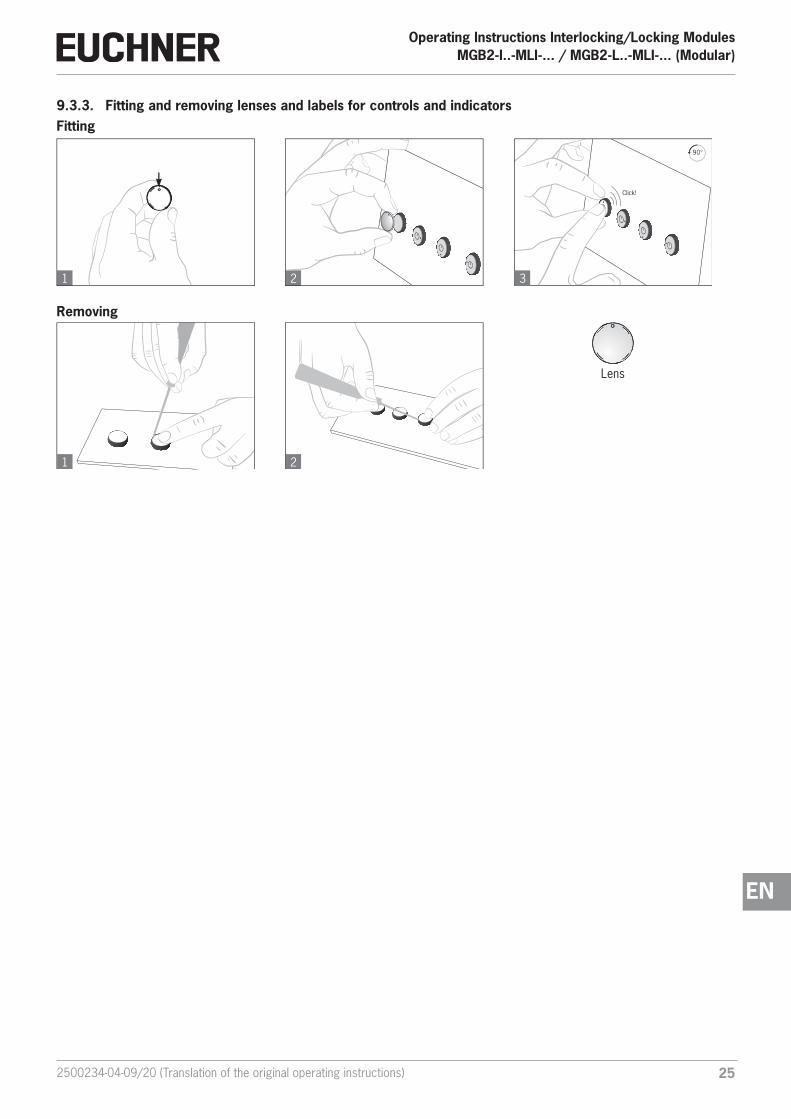
9.3.3. Fitting and removing lenses and labels for controls and indicators
1 2
2 3
90°
Click!
1
Fitting
Removing
Lens

Operating Instructions Interlocking/Locking ModulesMGB2-I..-MLI-... / MGB2-L..-MLI-... (Modular)
26 (Translation of the original operating instructions) 2500234-04-09/20
10. Changing the door hinge position10.1. Changing the interlocking/locking module to a different door hinge positionTo change the interlocking/locking module for doors with a different door hinge position, the module only needs to be rotated by 180°. Submodules installed in the module can also be rotated by 180° (see section 9.1. Replacing modules on page 23).
10.2. Changing actuating direction of the handle module(here: from right to left)
Important!
It is possible to make this change only when the bolt tongue is not extended and an escape release is not yet mounted.
As supplied, the handle module is set either for doors hinged on the right or for doors hinged on the left.
Based on the example of a handle module for doors hinged on the right this means: Ì The guard opens by pressing down the door handle. Ì The system is mounted the other way up for doors hinged on the left. In other words, the guard opens by pressing up the door handle (see Figure 10). For this reason the actuating direction of the door handle must be changed (see Figure 10 to Figure 15).
(Similarly on handle modules for doors hinged on the left)

272500234-04-09/20 (Translation of the original operating instructions)
Operating Instructions Interlocking/Locking ModulesMGB2-I..-MLI-... / MGB2-L..-MLI-... (Modular)
EN
CLOSED
OPEN
1
3
2
1 Press door handle up.2 Unscrew locking screws.3 Push cover aside.
Figure 10: Changing actuating direction, step 1 Figure 11: Changing actuating direction, steps 2 and 3
54
4 Lift the locking pin on the door handle using a screwdriver and hold it in this position.
5 Turn door handle to the right.
6
a
b
7
86 Only on the use of an escape release: using the Torx 10, turn the
joint counterclockwise from position (a) to position (b).7 Close cover.8 Screw in locking screws and tighten to 0.8 Nm.
Figure 12: Changing actuating direction, steps 4 and 5 Figure 13: Changing actuating direction, steps 6 to 8
T109
10
11
OPEN
CLOSED
9 Remove cap and undo screw.AT Change door handle by 90° in clockwise direction and re-fit.A Tighten screw to 2 Nm and re-fit cap. A State after changing.
Figure 14: Changing actuating direction, steps 9 to A Figure 15: Changing actuating direction, final state

Operating Instructions Interlocking/Locking ModulesMGB2-I..-MLI-... / MGB2-L..-MLI-... (Modular)
28 (Translation of the original operating instructions) 2500234-04-09/20
11. Protection against environmental effectsA lasting and correct safety function requires that the system must be protected against foreign bodies such as swarf, sand, blasting shot, etc., which can become lodged in the housing.
Pay attention to the following measures: Ì Seal unused connections using the covers provided. Ì Make sure the housing covers are correctly sealed and the cover screws are tightened to the necessary tightening torque. Ì Cover the device during painting work.
12. Controls and indicators
Figure 16: Indicators and controls
LED Description
POWERIlluminates if power supply correct Color: green
STATE Indicates the device stateColor: green
LOCKIndicates the state of the guard lockingColor: yellow
DIA Indicates faultsColor: red
SLOT 1Indicates the status of the submoduleColor: red/green
SLOT 2Indicates the status of the submoduleColor: red/green

292500234-04-09/20 (Translation of the original operating instructions)
Operating Instructions Interlocking/Locking ModulesMGB2-I..-MLI-... / MGB2-L..-MLI-... (Modular)
EN
13. Electrical connectionAll devices in a line of modules draw their power from a suitable bus module MBM. The connection is only allowed to be made to a bus module MBM or an upstream module.
For detailed instructions on the connection of the overall system, refer to the operating instructions for the bus module MBM used.
CAUTION
Risk of damage to equipment or malfunctions as a result of incorrect connection. Ì Pay attention to the instructions on correct connection in the operating instructions for the bus module MBM used.
13.1. Connecting modulesMGB2 Modular modules can either be connected together directly or using cables (see Figure 17: Connecting modules).
Each module has a top and a bottom connection. You can use either the bottom or the top connection or both if the module is between two other modules.
The bottom module connector is already integrated. To use the top connection, change its position. Use only the module connector intended to connect modules together (see table below). The maximum cable length for a line must not exceed 40 m.
156718
157025next module
direct plug
blind plug
stacklight
M12, 5-pin, male
M12, 5-pin, female
157024
MGB2-L...MCM-...
direct plug cable connect
157028
157029
stacklight
next modulecable connect
(M12, 5-pin, female)
(M12, 8-pin, female)
156718
157025next moduledirect plug
blind plug
157028next modulecable connect
(M12, 5-pin, female)
161345
Figure 17: Connecting modules

Operating Instructions Interlocking/Locking ModulesMGB2-I..-MLI-... / MGB2-L..-MLI-... (Modular)
30 (Translation of the original operating instructions) 2500234-04-09/20
Table 2: Overview of module connectors
Function Order no. Included?
Module connector M12, 5-pin plug 157024 1x *
Blanking cover 156718 1x *
Set with sealing caps for unused connections 156739 Yes
Module connector, 5-pin socket, for the direct connection of a further module 157025
No, must be ordered separately
Module connector M12, 5-pin socket, for the connection of a further module via a connecting cable 157028
Module connector M12, 5-pin socket, for the connection of a stacklight 161345
Module connector M12, 8-pin socket, for the connection of a stacklight 157029
Connecting cable M12, 5-pinSee catalog or www.euchner.com
Connecting cable M12, 8-pin
* Not for MGB2-…-Y0000-…
13.2. Using submodulesEach interlocking/locking module can contain up to two submodules. For an exact description of the individual submodules as well as information on compatibility, refer to the data sheet for the related submodule. This is included with each submodule.
Important!
Ì In the modules described here it is only allowed to install submodules of connection types P, R and N. For information on the related connection type of a submodule, refer to the sticker on the rear of the submodule or the data sheet for the related submodule. This is included with each submod-ule.
Ì Only one submodule with an emergency stop is allowed to be installed per module.
Ì On using a submodule with labeling fields, pay attention to the correct alignment of the modules in relation to the labeling fields. Incorrect assignments can cause serious malfunctions in your instal-lation.
Ì Unused submodule slots must be fitted with a cover (order number 126372).
Ì Avoid touching the contacts on the underside of the submodule. Risk of ESD damage and contact problems due to soiling.

312500234-04-09/20 (Translation of the original operating instructions)
Operating Instructions Interlocking/Locking ModulesMGB2-I..-MLI-... / MGB2-L..-MLI-... (Modular)
EN
14. Data blocks for interlocking/locking module MGB2-I or MGB2-LImportant!
You will find the exact data structure for your device on the data sheet enclosed. You will find a detailed description of the safe and non-safe data blocks in the operating instructions for your bus module MBM.
15. SetupThe device is automatically in operation after powering up the bus module MBM. For detailed instructions on setup, refer to the operating instructions for your bus module MBM.
You can see the current operating status on the LEDs on the module (see 12. Controls and indicators on page 28 and 16. System status table, module LEDs on page 33). You will also find information on fault detection there.
15.1. Teach-in operation (only for MGB2 unicode)The handle module must be assigned to the locking module using a teach-in function before the system comprising inter-locking/locking module and handle module forms a functional unit.
During a teach-in operation, the module is in the safe state (no safe bits are set).
Important!
Ì A system that has not yet been taught-in remains in the teach-in standby state until a handle mod-ule has been taught-in. Interlocking/locking modules already taught-in remain in the teach-in stand-by state for 3 min after the system start.
Ì The interlocking/locking module disables the code for the previous handle module if a new handle module is taught-in. Teach-in is not possible again immediately for this device if a new teach-in operation is carried out. The disabled code is deleted in the locking module only after a third code has been taught-in.
Ì If the interlocking/locking module detects a disabled or unsuitable handle module while the module is in the teach-in standby state, a teach-in error is indicated after 30 s. Ì The interlocking/locking module can be operated only with the last handle module taught-in. Ì If, in the teach-in standby state, the interlocking/locking module detects the handle module last taught-in, the teach-in standby state is ended immediately and the interlocking/locking module changes to normal operation. Ì If the bolt tongue is in the actuating range for less than 30 s, the handle module is not taught-in and the device indicates a teach-in error.
Teaching-in handle module
1. Fit handle module.
2. Close safety device. Check for correct alignment and distance using the markings on the interlocking/locking module and re-adjust if necessary.
3. Insert bolt tongue into the interlocking/locking module.
4. Connect interlocking/locking module to the bus module MBM. The bus module must be in operation for this purpose.
¨ Teach-in operation starts, green LED (State) flashes slowly (approx. 1 Hz). During the teach-in operation, the locking module checks whether the handle module is a disabled handle module. Provided this is not the case, the teach-in oper-ation is completed after approx. 30 seconds, and the green LED (State) goes out. The new code has now been stored, and the old code is disabled. The STATE and DIA LEDs on the interlocking/locking module flash alternately if the teach-in operation was successful.
5. Restart overall system via the bus module MBM. For this purpose, disconnect the bus module from the power supply for a few seconds.

Operating Instructions Interlocking/Locking ModulesMGB2-I..-MLI-... / MGB2-L..-MLI-... (Modular)
32 (Translation of the original operating instructions) 2500234-04-09/20
15.2. Mechanical function testIt must be possible to insert the bolt tongue easily into the locking module. To check, close guard several times and actuate door handle.
If available, check function of the escape release. With active guard locking it must be possible to operate the escape release from the inside without excessive effort (approx. 5 Nm).
15.3. Electrical function test1. Close all guards and insert the bolt tongue into the locking module.
2. Activate guard locking. Ì The machine must not start automatically. Ì It must not be possible to open the guard. Ì The following applies to MGB2-I..: The green LED (State) is illuminated. Ì The following applies to MGB2-L..: The green LED (State) and the yellow LED (Lock) are illuminated.
3. Enable operation in the control system. Ì It must not be possible to deactivate guard locking as long as operation is enabled.
4. Disable operation in the control system and deactivate guard locking. Ì The guard must remain locked until there is no longer any risk of injury. Ì It must not be possible to start the machine as long as guard locking is deactivated. Ì It must be possible to open the guard.
Repeat steps 2-4 for each guard.
15.4. Replacing a module For instructions on replacement, refer to the operating instructions for your bus module MBM. After the replacement of an interlocking/locking module or a handle module, a teach-in operation may be necessary. See 15.1. Teach-in operation (only for MGB2 unicode) on page 31.

332500234-04-09/20 (Translation of the original operating instructions)
Operating Instructions Interlocking/Locking ModulesMGB2-I..-MLI-... / MGB2-L..-MLI-... (Modular)
EN
16. System status table, module LEDsAll diagnostic messages are listed below. The scope of the possible messages may differ depending on the type and number of modules/submodules used.
16.1. System indications if there are faults (module LEDs)If there are faults, the bit LM.E_G is set. After the fault has been rectified, this can be acknowledged using the bit LM.ACK_G. The bit LM.E_G is reset during this process. Exception: escape release (see 19.2. Fault on actuating the escape release on page 38)
Operating mode
LED indicator
Devi
ce d
iagn
ostic
s,
rela
ted
faul
t/st
atus
bit
State
POW
ER (g
n)
STAT
E (g
n)
Lock
(ye)
, onl
y M
GB
2-L1
/-L2
DIA
(rd)
Fault display
1 x LM.E_G Handle module teach-in error (e.g. teach-in operation interrupt-ed too early), configuration teach-in error
3 x LM.E_G Handle module read error (e.g. error in code or code cannot be read) 2)
5 x LM.E_G Environment error, disabled actuator, power supply outside the permissible range
LM.E_G Internal fault (e.g. component faulty, data error) 1)
1 x LM.E_G Plausibility error, signal sequence incorrect, e.g. broken bolt tongue recognized 2)
1 x LM.F_ER After actuation of the escape release 3)
1 x
BM.E_MLI MLI communication error (indication on bus module)
Key to symbols
LED not illuminated
LED illuminated
3 x LED flashes three times
X Any state
1) Latching fault; use corresponding output bit LM.ACK_G to reset2) Non-latching fault; open guard and close it again to reset3) Non-latching fault; use corresponding output bit LM.ACK_ER to reset
Important: If you do not find the displayed device status in the system status table, this indicates an internal device fault. In this case, you should contact the manufacturer.

Operating Instructions Interlocking/Locking ModulesMGB2-I..-MLI-... / MGB2-L..-MLI-... (Modular)
34 (Translation of the original operating instructions) 2500234-04-09/20
16.2. System indications during setup, teach-in and normal operation
Ope
ratin
g m
ode
LED
indi
cato
r
Door position
Position of the bolt tongue
Guard locking control LM.FO_CL (depending on setting also LM.O.CL)
Device diagnosticsStatus bit LM.I_OD
Bolt position Status bit LM.I_OT
Bolt position (SK) Safe input bit LM.FI_SKStatus bit LM.I_SK
Guard locking Status bit LM.I_OL
Guard locking status (ÜK) Safe input bit LM.FI_UKStatus bit LM.I_UK
Stat
e
POWER (gn)
STATE (gn)
Lock (ye), only MGB2-L1/-L2
DIA (rd)
Nor
mal
ope
ratio
n
long
OFF
sh
ort O
Nop
enno
t in
sert
edof
fof
fof
fof
fof
fof
fN
orm
al o
pera
tion,
doo
r op
en
long
ON
sh
ort O
FFcl
osed
not
inse
rted
off
onof
fof
fof
fof
fN
orm
al o
pera
tion,
doo
r cl
osed
long
ON
sh
ort
OFF
clos
edin
sert
edof
fon
onon
off
off
Nor
mal
ope
ratio
n, d
oor
clos
ed, b
olt t
ongu
e in
sert
ed
clos
edin
sert
edon
onon
onon
onN
orm
al o
pera
tion,
doo
r cl
osed
and
lock
ed
Xfla
shin
g qu
ickl
yX
not
inse
rted
onof
fof
fof
fof
fof
fRe
ady
for
guar
d lo
ckin
g, g
uard
lock
ing
is a
ctiv
e, b
olt
tong
ue n
ot in
sert
ed
Teac
h-in
sta
ndby
(onl
y fo
r M
GB2
un
icod
e)3
xop
enno
t in
sert
edof
fof
fof
fof
fof
fof
fDo
or o
pen;
uni
t is
read
y fo
r te
ach-
in o
f ano
ther
han
dle
mod
ule
(onl
y sh
ort t
ime
afte
r po
wer
-up)
Setu
p(o
nly
for
MG
B2
unic
ode)
1 Hz
clos
edin
sert
edon
onon
off
onof
fTe
ach-
in o
pera
tion
alte
rnat
ely
flash
-in
g ST
ATE
/DIA
XX
off
off
off
off
off
Posi
tive
ackn
owle
dgm
ent a
fter
com
plet
ion
of te
ach-
in
oper
atio
n
Key
to s
ymbo
ls
LED
not i
llum
inat
ed
LED
illum
inat
ed
1 Hz
LED
flash
es a
t 1 H
z
3 x
LED
flash
es th
ree
times
XAn
y st
ate
Impo
rtan
t: If
you
do n
ot fi
nd th
e di
spla
yed
devi
ce s
tatu
s in
the
syst
em s
tatu
s ta
ble,
this
indi
cate
s an
inte
rnal
dev
ice
faul
t. In
this
cas
e, y
ou s
houl
d co
ntac
t the
man
ufac
ture
r.

352500234-04-09/20 (Translation of the original operating instructions)
Operating Instructions Interlocking/Locking ModulesMGB2-I..-MLI-... / MGB2-L..-MLI-... (Modular)
EN
17. System status table (slot LEDs)If a fault occurs on the submodule, the bit LM.E_SM.. is set. As soon as the fault has been corrected, it is reset automatically (non-latching fault).
Fault displaySLOT1 / SLOT2 LED Meaning Measures
OFF A submodule is not used or submodule functions without faults
-
Red ONGreen flashes 1 x
Submodule missing although a submodule was includ-ed in the last configuration
Insert suitable submodule or adapt configuration.
Red ONGreen flashes 2 x
Submodule is installed rotated by 180° Case 1: Submodule type is correct, but submodule must be installed rotated by 180°. Case 2: If it is intended to change the configuration, the system must be restarted so that the required configuration is taught-in.Case 3: Alignment is irrelevant for this submodule, but the parameter for alignment detection is active. Change parameter for alignment detection and restart system.
Red ONGreen flashes 3 x
Submodule does not correspond to the submodule type configured last
Insert submodule of appropriate type or adapt configuration.
Red ON Internal fault in the submodule Replace submodule.
Ì If the problem persists: replace the base unit.
Red flashing (1 Hz)The DIA LED also illuminates
Faults in safety engineering, latchingOther input errors on the submodule
Restart system.
Ì If the problem persists: replace the submodule.
Ì If the problem persists: replace the base unit.
Red flashingGreen OFF
Enabling switch discrepancy error Release enabling switch and press again.
Ì If the problem persists: check the cable and connection.
Ì If the problem persists: replace the submodule.
Ì If the problem persists: replace the base unit.

Operating Instructions Interlocking/Locking ModulesMGB2-I..-MLI-... / MGB2-L..-MLI-... (Modular)
36 (Translation of the original operating instructions) 2500234-04-09/20
18. Technical dataNOTICE
If a data sheet is included with the product, the information on the data sheet applies.
Parameter Value
Housing material Fiber glass reinforced plastic Die-cast zinc, nickel plated,
stainless steel, powder-coated sheet steel
Dimensions See dimension drawing
Weight of MGB2 (interlocking/locking module, without submodules) 1.0 kg
Weight of handle module 1.1 kg
Weight of escape release 0.75 kg
Ambient temperature -25 … +55 °C
Degree of protection IP65 1)
Safety class III
Degree of contamination 3
Installation orientation Any
Locking force Fzh acc. to GS-ET-19 2,000 N
Power supply Via bus module MBM
Connection M12, 5-pin (EUCHNER module plug connector MLI)
Current consumption, max. (without submodules) 350 mA
Current consumption, max., per submodule 30 mA
Rated impulse withstand voltage Uimp 0.5 kV
Resilience to vibration and shock Acc. to EN 60947-5-3
EMC protection requirements Acc. to EN 61000-4 and DIN EN 61326-3-1
Risk times, max. (turn-off times) 2)
- Monitoring of the position of the guard- Monitoring of guard locking- Activation of guard locking
See information in the operating instructions for your bus module
Reliability values acc. to EN ISO 13849-1:2015
Category 4
Performance Level PL e
MTTFd 3) 820 years
DC 99%
Mission time 20 years
PFHd 4)
- Monitoring of guard locking and the position of the guard- Control of guard locking- Monitoring of the position of the guard- Evaluation of safety signals in submodules installed
2.62 x 10⁻⁹
1) Only with correctly mounted connecting cables and submodules.2) The risk time is the max. time between the change in the input status and the clearing of the corresponding bit in the bus protocol.3) Fixed failure rate without consideration of faults in wearing parts.

372500234-04-09/20 (Translation of the original operating instructions)
Operating Instructions Interlocking/Locking ModulesMGB2-I..-MLI-... / MGB2-L..-MLI-... (Modular)
EN
18.1. Radio frequency approvals
FCC ID: 2AJ58-02IC: 22052-02
FCC/IC-Requirements
This device complies with part 15 of the FCC Rules and with Industry Canada’s licence-exempt RSSs. Operation is subject to the following two conditions:
1) This device may not cause harmful interference, and
2) this device must accept any interference received, including interference that may cause undesired operation.
Changes or modifications not expressly approved by the party responsible for compliance could void the user‘s authority
to operate the equipment.
NOTE: This equipment has been tested and found to comply with the limits for a Class A digital device, pursuant to part 15 of the FCC Rules. These limits are designed to provide reasonable protection against harmful interference when the equipment is operated in a commercial environment. This equipment generates, uses, and can radiate radio frequency energy and, if not installed and used in accordance with the instruction manual, may cause harmful interference to radio communications.
Operation of this equipment in a residential area is likely to cause harmful interference in which case the user will be required to correct the interference at his own expense.
Le présent appareil est conforme aux CNR d’Industrie Canada applicables aux appareils radio exempts de licence. L’exploita-tion est autorisée aux deux conditions suivantes :
(1) l’appareil ne doit pas produire de brouillage, et
(2) l’utilisateur de l’appareil doit accepter tout brouillage radioélectrique subi, même si le brouillage est susceptible d’en compromettre le fonctionnement.

Operating Instructions Interlocking/Locking ModulesMGB2-I..-MLI-... / MGB2-L..-MLI-... (Modular)
38 (Translation of the original operating instructions) 2500234-04-09/20
19. Troubleshooting and assistanceYou will find detailed information on diagnostics and troubleshooting in the operating instructions for your bus module MBM. The following information covers only faults related to the interlocking/locking module MGB2.
19.1. Resetting general faultsProceed as follows:
1. Acknowledge fault using output bit LM.ACK_G.
2. Close guard if necessary and switch on guard locking.
¨ The system is in normal operation again.
19.2. Fault on actuating the escape releaseThis fault behavior must be configured correspondingly in the parameters. You can do this in the configuration software for your control system. In the Module parameters dialog, set the value for the Fault on actuating the escape release field in the Escape release fault section to yes. You will find information on configuration in the operating instructions for your bus module MBM.
To achieve monitoring of the locking element in category 4, PL e according to EN ISO 13849-1, internal monitoring logic is integrated into every locking module.
Result: Bit LM.F_ER is set when the escape release is actuated (see 16.2. System indications during setup, teach-in and normal operation on page 34).
The bit LM.ACK_ER must be set for at least 100 ms to acknowledge the fault.
Doo
r po
sitio
n
Posi
tion
of th
e bo
lt to
ngue
Gua
rd lo
ckin
g
Bolt
posi
tion
stat
us b
it LM.I_OT
Gua
rd lo
ckin
g st
atus
bit LM.I_OL
ÜK in
put b
it LM.FI_UK
Devi
ce d
iagn
ostic
s st
atus
bit
LM.I_OD
LED indicator
State
Pow
er (g
n)
Stat
e (g
n)
Lock
(ye)
DIA
(rd)
X X X off off off X 1 x Signal sequence incorrect (e.g. after actuation of the escape release)
LED not illuminated
LED illuminated
3 x LED flashes three times
X Any state
19.3. Resetting system to factory settingsFor instructions on resetting to factory settings, refer to the operating instructions for your bus module MBM.

392500234-04-09/20 (Translation of the original operating instructions)
Operating Instructions Interlocking/Locking ModulesMGB2-I..-MLI-... / MGB2-L..-MLI-... (Modular)
EN
20. ServiceIf servicing is required, please contact:EUCHNER GmbH + Co. KGKohlhammerstraße 1670771 Leinfelden-EchterdingenGermany
Service telephone:
+49 711 7597-500
E-mail:
Internet:
www.euchner.com
21. Inspection and serviceWARNING
Loss of the safety function because of damage to the device.In case of damage, the affected module must be replaced completely. Only accessories or spare parts that can be ordered from EUCHNER may be replaced.
Regular inspection of the following is necessary to ensure trouble-free long-term operation: Ì Check the safety function (see chapter 15.3. Electrical function test on page 32) Ì Check the secure mounting of the devices and the connections Ì Check for soiling
No servicing is required. Repairs to the device are only allowed to be made by the manufacturer.
NOTICE
The year of manufacture can be seen in the lower right corner of the rating plate.

Operating Instructions Interlocking/Locking ModulesMGB2-I..-MLI-... / MGB2-L..-MLI-... (Modular)
40 (Translation of the original operating instructions) 2500234-04-09/20
22. Declaration of conformity

412500234-04-09/20 (Translation of the original operating instructions)
Operating Instructions Interlocking/Locking ModulesMGB2-I..-MLI-... / MGB2-L..-MLI-... (Modular)
EN

Operating Instructions Interlocking/Locking ModulesMGB2-I..-MLI-... / MGB2-L..-MLI-... (Modular)
42 (Translation of the original operating instructions) 2500234-04-09/20

432500234-04-09/20 (Translation of the original operating instructions)
Operating Instructions Interlocking/Locking ModulesMGB2-I..-MLI-... / MGB2-L..-MLI-... (Modular)
EN

EUCHNER GmbH + Co. KGKohlhammerstraße 1670771 [email protected]
Edition:2500234-04-09/20Title: Operating Instructions Interlocking/Locking Modules MGB2-I..-MLI-... / MGB2-L..-MLI-... (Modular) and from V1.00.0 (Translation of the original operating instructions)Copyright:© EUCHNER GmbH + Co. KG, 09/2020Subject to technical modifications; no responsibility is accept-ed for the accuracy of this information.